EP1920862A2 - Plaquette de coupe et porte-outil - Google Patents
Plaquette de coupe et porte-outil Download PDFInfo
- Publication number
- EP1920862A2 EP1920862A2 EP07425693A EP07425693A EP1920862A2 EP 1920862 A2 EP1920862 A2 EP 1920862A2 EP 07425693 A EP07425693 A EP 07425693A EP 07425693 A EP07425693 A EP 07425693A EP 1920862 A2 EP1920862 A2 EP 1920862A2
- Authority
- EP
- European Patent Office
- Prior art keywords
- ref
- insert
- accordance
- tool
- bracket
- Prior art date
- Legal status (The legal status is an assumption and is not a legal conclusion. Google has not performed a legal analysis and makes no representation as to the accuracy of the status listed.)
- Withdrawn
Links
Images


Classifications
-
- B—PERFORMING OPERATIONS; TRANSPORTING
- B23—MACHINE TOOLS; METAL-WORKING NOT OTHERWISE PROVIDED FOR
- B23B—TURNING; BORING
- B23B27/00—Tools for turning or boring machines; Tools of a similar kind in general; Accessories therefor
- B23B27/14—Cutting tools of which the bits or tips or cutting inserts are of special material
- B23B27/16—Cutting tools of which the bits or tips or cutting inserts are of special material with exchangeable cutting bits or cutting inserts, e.g. able to be clamped
- B23B27/1685—Adjustable position of the cutting inserts
- B23B27/1696—Angular position of the cutting insert adjustable around an axis generally perpendicularly to the chip-forming plane
-
- B—PERFORMING OPERATIONS; TRANSPORTING
- B23—MACHINE TOOLS; METAL-WORKING NOT OTHERWISE PROVIDED FOR
- B23B—TURNING; BORING
- B23B27/00—Tools for turning or boring machines; Tools of a similar kind in general; Accessories therefor
- B23B27/14—Cutting tools of which the bits or tips or cutting inserts are of special material
- B23B27/16—Cutting tools of which the bits or tips or cutting inserts are of special material with exchangeable cutting bits or cutting inserts, e.g. able to be clamped
- B23B27/1625—Cutting tools of which the bits or tips or cutting inserts are of special material with exchangeable cutting bits or cutting inserts, e.g. able to be clamped with plate-like cutting inserts of special shape clamped by a clamping member acting almost perpendicularly on the chip-forming plane
-
- B—PERFORMING OPERATIONS; TRANSPORTING
- B23—MACHINE TOOLS; METAL-WORKING NOT OTHERWISE PROVIDED FOR
- B23B—TURNING; BORING
- B23B27/00—Tools for turning or boring machines; Tools of a similar kind in general; Accessories therefor
- B23B27/14—Cutting tools of which the bits or tips or cutting inserts are of special material
- B23B27/16—Cutting tools of which the bits or tips or cutting inserts are of special material with exchangeable cutting bits or cutting inserts, e.g. able to be clamped
- B23B27/1644—Cutting tools of which the bits or tips or cutting inserts are of special material with exchangeable cutting bits or cutting inserts, e.g. able to be clamped with plate-like cutting inserts of special shape clamped by a clamping member acting almost perpendicularly on the chip-forming plane and at the same time upon the wall of a hole in the cutting insert
-
- B—PERFORMING OPERATIONS; TRANSPORTING
- B23—MACHINE TOOLS; METAL-WORKING NOT OTHERWISE PROVIDED FOR
- B23B—TURNING; BORING
- B23B27/00—Tools for turning or boring machines; Tools of a similar kind in general; Accessories therefor
- B23B27/14—Cutting tools of which the bits or tips or cutting inserts are of special material
- B23B27/16—Cutting tools of which the bits or tips or cutting inserts are of special material with exchangeable cutting bits or cutting inserts, e.g. able to be clamped
- B23B27/1655—Adjustable position of the plate-like cutting inserts of special form
-
- B—PERFORMING OPERATIONS; TRANSPORTING
- B23—MACHINE TOOLS; METAL-WORKING NOT OTHERWISE PROVIDED FOR
- B23B—TURNING; BORING
- B23B2200/00—Details of cutting inserts
- B23B2200/04—Overall shape
- B23B2200/0423—Irregular
-
- B—PERFORMING OPERATIONS; TRANSPORTING
- B23—MACHINE TOOLS; METAL-WORKING NOT OTHERWISE PROVIDED FOR
- B23B—TURNING; BORING
- B23B2200/00—Details of cutting inserts
- B23B2200/04—Overall shape
- B23B2200/048—Star form
-
- B—PERFORMING OPERATIONS; TRANSPORTING
- B23—MACHINE TOOLS; METAL-WORKING NOT OTHERWISE PROVIDED FOR
- B23B—TURNING; BORING
- B23B2200/00—Details of cutting inserts
- B23B2200/12—Side or flank surfaces
- B23B2200/123—Side or flank surfaces curved
-
- B—PERFORMING OPERATIONS; TRANSPORTING
- B23—MACHINE TOOLS; METAL-WORKING NOT OTHERWISE PROVIDED FOR
- B23B—TURNING; BORING
- B23B2200/00—Details of cutting inserts
- B23B2200/20—Top or side views of the cutting edge
- B23B2200/201—Details of the nose radius and immediately surrounding area
-
- B—PERFORMING OPERATIONS; TRANSPORTING
- B23—MACHINE TOOLS; METAL-WORKING NOT OTHERWISE PROVIDED FOR
- B23B—TURNING; BORING
- B23B2200/00—Details of cutting inserts
- B23B2200/36—Other features of cutting inserts not covered by B23B2200/04 - B23B2200/32
- B23B2200/3627—Indexing
-
- B—PERFORMING OPERATIONS; TRANSPORTING
- B23—MACHINE TOOLS; METAL-WORKING NOT OTHERWISE PROVIDED FOR
- B23B—TURNING; BORING
- B23B2200/00—Details of cutting inserts
- B23B2200/36—Other features of cutting inserts not covered by B23B2200/04 - B23B2200/32
- B23B2200/3627—Indexing
- B23B2200/3636—Indexing with cutting geometries differing according to the indexed position
-
- B—PERFORMING OPERATIONS; TRANSPORTING
- B23—MACHINE TOOLS; METAL-WORKING NOT OTHERWISE PROVIDED FOR
- B23B—TURNING; BORING
- B23B2205/00—Fixation of cutting inserts in holders
- B23B2205/12—Seats for cutting inserts
-
- B—PERFORMING OPERATIONS; TRANSPORTING
- B23—MACHINE TOOLS; METAL-WORKING NOT OTHERWISE PROVIDED FOR
- B23B—TURNING; BORING
- B23B2205/00—Fixation of cutting inserts in holders
- B23B2205/16—Shims
Definitions
- This invention pertains to an insert for turning and concerning locking tool.
- Manufactured pieces as an example, metallic bars, are kept in rotation while a cutting insert moves along pieces surface, removing a part of material. This insert is securely supported and locked by an appropriate insert holder tool controlled by the lathe.
- turning can provide pieces external surface manufacturing, or the internal one or the frontal one. By turning, as well as removing pieces superficial material under control, it is possible, for example, threading, profiling and peeling these pieces.
- Notoriously inserts for turning are classified by a specific ISO standard. As an example, ISO standard distinguishes inserts depending on material, shape, cutting surface number, according to the kind of manufacturing material (aluminium, steel, ceramic materials, etc.) and the manufacture to perform, etc..
- Inserts are made of different materials as, for example, tungsten carbides, Titanium carbides compound (TiC) and Titanium nitride (TiN), ceramic and polycrystalline materials (cubic boron nitride or polycrystalline diamond).
- Inserts are marketed under different shape, each of these optimized to provide highest performances concerning specific manufacturing of destination.
- rhombus shaped inserts are suggested for axial turning and profiling
- square shaped inserts are suggested for faceting
- circular shaped inserts are suggested for plunge grooving.
- triangular shaped inserts are suggested for axial turning, rhombus shaped inserts suggested for profiling and faceting.
- Same shaped inserts differentiate because of summit angle among sides; these angles determine cutting angles, depending on below rake, front rake, etc..
- Locking tools provide to keep inserts in the right position for manufacturing, minimizing vibrations.
- locking tools differentiate because of the used mechanism to locking inserts.
- well-known are lever locking tools, wedge-shaped bracket locking tools, pivot and bracket locking tools, screw locking tools, bracket locking tools, "rigid clamping" locking tools, etc..
- Traditional inserts have a number of side-cutting edges depending on sides number. Side-cutting edges' size depend on summit angles width among sides. As an example, equilateral triangle shaped inserts normally have three or six side-cutting edges because each side-cutting edge is determined by a part of insert corner. Rhombus shaped inserts normally have four or eight side-cutting edges.Ttriangular shaped inserts featured by summit angle wider than 60° have six or twelve side-cutting edges. For further example, look at turning inserts manufacturer catalogues, as SANDVIK for Coromant series, edition 2002.
- United States patent filing US 2006/0216121 has as object a rhombus shaped insert and concerning locking tool.
- the insert can be fixed on concerning tool using a screw.
- Insert upper surface is equipped with side-cutting edges and lower surface is supplied with cavities fitting locking tool complementary protrusions to maximize connection holding.
- the insert is rhombus shaped or trapezoidal shaped.
- Modem lathes are provided with automatic devices to change tools.
- lathes are equipped with various interchangeable locking tools, each of these supplied with a turning insert, and lathe arranges tool automatically, and then the suitable insert to pursue manufacturing.
- Disadvantageously traditional inserts can be arranged with variable cutting angles and/or rakes in limited time intervals. Therefore it's necessary supply turnings with a lot of inserts to be able to substitute worn out inserts quickly, or substitute an insert with another one having different features that allow using cutting angle/rake more useful in order to the manufacturing in operation. Management costs for companies doing manufacturing are negatively influenced because of necessity of acquiring and stocking various inserts.
- the aim of this industrial invention is to offer a turning insert allowing resolving simply and effectively traditional inserts inconveniences, allowing minimizing the number of inserts to arrange on lathes, both similar inserts and different features inserts.
- Another aim of this industrial invention is to offer a turning insert allowing unifying traditional inserts performances simply and effectively, allowing at the same time minimizing the number of inserts to arrange on lathes, both similar inserts and different features inserts.
- an aim of this industrial invention is to offer a turning insert equipped with more side-cutting edges compared with corresponding traditional one.
- Another aim of this industrial invention is to offer a locking tool for inserts resolving traditional tools inconveniences simply and effectively, proving at the same time cheap and easy to use.
- a further aim of this industrial invention is to offer a locking tool for inserts allowing unifying traditional different tools performances simply and effectively, turning out to be at the same time cheap and easy to use.
- an aim of this industrial invention is to offer a locking tool allowing effectively supporting turning inserts featured by different shape, and in different position, so that same inserts can be used with different cutting angles.
- all insert sides are curved towards insert centre.
- curving it is possible to realize segmented sides.
- insert sides can be different among them, offering obvious advantages in order to the insert versatility.
- the insert basically has triangular shape, or rather on the plan is determined by three sides preferably featured by the same length. Unlike triangular shaped inserts or available triangles on the market, in accordance with this industrial invention, the insert is equipped with summit angles less wide than 60° all. Angles can be equal among them or different, as long as less wide than 60°. As an example, first side-cutting edge can have a 58° width summit angle, the second one can have a 57° width summit angle and the third one can have a 56° width summit angle.
- lateral surfaces determining summit angles are tapered. Or rather, looking at insert up surface, on the plan the sides are curved towards insert inside, as an example, towards its axis. In other words, lateral surfaces have a band radius towards insert axis. Sides can be segment, or rather insert lateral surfaces can be composed of many layers.
- the insert basically has quadrangular shape and summit angles are less wide than 90° all. Angles can be equal or different among them. On the plan, sides determining summit angles are curved towards insert centre or segmented or tapered.
- Triangular shaped inserts can have three or six side-cutting edges (three on each insert face).
- Quadrangular shaped inserts can have four or eight side-cutting edges, hexagonal shaped inserts can have six or twelve side-cutting edges, etc..
- triangular shaped insert's three or six side-cutting edges can have different features and, then, insert allows executing more different manufacturing's compared with a traditional insert equipped with three or six equal side-cutting edges.
- insert versatility is maximized. Therefore, inserts number required to equip a lathe is lower than for traditional inserts, under the same work condition. This inserts number reduction determines easier spare parts store management and cut in costs.
- Insert versatility is maximized when same insert is used put together with a locking tool inserts holder, in accordance with this invention allowing to arrange insert equipped by different cutting angles.
- a locking tool for turning inserts including a main part equipped with a surface supporting a turning insert, directly or interposing a centring head for that insert, and clamping equipments for that insert and for that centring head on the main part, turning insert featured by interchangeability of clamping equipment and/or centring head having at least a perimetrical supporting surface for that insert, and that supporting surface oriented to position insert in conformity with a specific cutting angle.
- locking tool can be used either combined with the insert in accordance with this industrial invention or with traditional inserts ISO-type or equivalent.
- the insert can be directly arranged on supporting surface and locked by concerning clamping equipment. Insert flanks rest on one or more head supporting surfaces, for example a bracket.
- the insert can be arranged and locked on centring head, which is locked on tool's supporting surface.
- Insert flanks rest on one or more centring head's supporting surfaces and head's flanks rest on one or more insert's contact surfaces.
- Perimetrical supporting surfaces preferably are wedge-type, or rather inclined compared with supporting surface.
- Clamping equipments can be a screw, a pin, a bracket, a wedge shaped bracket, or equivalent and preferably equipped with a pivot, or rather a protrusion intended for being put in an insert cavity to convey locking pressure.
- the bracket, or the wedge shaped bracket can be restrained to the tool main part by a screw or a pin and is equipped with at least a wedged shaped part to use a corresponding groove made from tool main part. This way, the bracket, or the wedge shaped bracket, cannot move after being screwed in tool main part.
- the centring head is drilled and can be fixed at tool supporting surface by a screw or a pin.
- insert operative side-cutting edge works with first cutting angle.
- first cutting angle it's enough substitute centring head, if there's one, with another head equipped with differently oriented supporting surface compared with supporting surface of the head to substitute.
- bracket or the wedge shaped bracket
- bracket with another bracket having supporting surface oriented as desired. This way, it's possible to arrange the insert to work with desired cutting angle.
- the locking tool can be double wedge type, three wedges type, etc..
- Tool main part is a circular or squared or rectangular section shank and can be made of usual materials used for this kind of tools.
- the insert is put on supporting surface with at least a flank resting on bracket (or wedge shaped bracket) supporting surface and is kept in position with pressure exercised by the bracket's (or wedge shaped bracket's) traction pivot screwed in the tool.
- the insert is put on centring head, respectively put on supporting surface, with at least a flank resting on a head supporting surface, and is kept in position with the pressure exercised by the pivot of corresponding clamping equipment screwed in the tool.
- Locking tool in accordance with this industrial invention, is featured by the remarkable advantage of allowing use of turning inserts depending on different cutting angles. This way, it's possible to minimize different inserts supplies to store, having an effective economic savings.
- the tool allows maximizing insert versatility.
- the insert can be equipped with side-cutting edges with different angles and then tool can support insert in different position to use different insert side-cutting edges.
- triangular shaped insert can be supported in three different positions to use the three side-cutting edge of insert. Each position corresponds with a insert rotation on supporting surface.
- Branch's expert will understand that various positions and number of different side-cutting edges offered to the user is remarkably higher compared with traditional systems.
- the repositioning of inserts on the locking tool concerning this invention is simple and quick. It's enough unscrewing clamping bracket and substitute it with a different bracket, or rather a second bracket featured by supporting surfaces differently oriented compared with changed bracket, or rescrewing the clamping bracket in a different position on tool supporting surface.
- tool of the invention includes at least a supporting surface, preferably at least two.
- the supporting surface is wedge type.
- Supporting surface can be curved, or rather can extend with bend radius from the tool's supporting pivot axis.
- the locking tool also allows reducing machinery equipment's non-operating times; or rather times necessary to arrange an insert in work position. Compared with traditional solutions, it's not necessary disassembling locking tool from lathe to substitute it with another tool equipped with a new insert. In fact the tool allows repositioning insert already supported, in order to obtain the cutting angle desired. It's enough modifying the clamping bracket or the position of the clamping bracket.
- FIG. 1 In order to the figure n. 1, is shown a first triangular shaped insert 1 (ref. 1, fig. 1 ) in accordance with this invention.
- figure n. 1 shows the insert up side of insert 1 (ref. 1, fig. 1 ) that is equipped with a second below side equal to the first.
- Insert 1's thickness (ref. 1, fig. 1 ) can be, for example, to 4 mm.
- insert 1's thickness (ref. 1, fig. 1 ) can be equal to the thickness typically used for turning inserts.
- the insert 1 (ref. 1, fig. 1 ) can be realized in a traditional material, for example, a ceramic one, a sintered or polycrystalline one, etc..
- the insert 1 (ref. 1, fig. 1 ) has a central cavity 2 (ref. 2, fig. 1 ) passing through the engagement by clamping equipments to a locking tool.
- the insert 1 (ref. 1, fig. 1 ) shown in figure is equipped with three side-cutting edges T1-T3 (ref. T1-T3, fig. 1 ) determined by summit angles included among insert sides. Every side-cutting edges T1-T3 (ref. T1-T3, fig. 1 ) have acute summit angles, and in example shown in figure these angles are less wide 60°, on the contrary of traditional inserts featured by summit angles equal or wider than 60° (triangular shaped inserts).
- the insert 1 (ref. 1, fig. 1 ) represents a central symmetry as regards to cavity 2's centre (ref. 2, fig. 1 ) (are shown angles between median lines equal to 120° width) and therefore side-cutting edges T1-T3 (ref. T1-T3, fig. 1 ) are identical.
- band radius can be different for each side 3-5 (ref. 3-5, fig. 1 ), so that summit angles are different among them.
- T1 side-cutting edge (ref. T1, fig. 1 ) can have a summit angle equal to 59° width
- T2 side-cutting edge (ref. T2, fig. 1 ) can have a summit angle equal to 58° width
- T3 side-cutting edge (ref. T3, fig. 1 ) can have a summit angle equal to 57° width.
- insert 1 is more versatile because its side-cutting edges can have different features among them.
- Figure n. 2 shows a different insert 1' (ref. 1', fig. 2 ) having quadrangular shape, in accordance with this invention.
- insert 1' (ref. 1', fig. 2 ) is equipped with a central cavity 2'(ref. 2', fig. 2 ).
- Summit angles determining four side-cutting edges T1'-T4'(ref. T1'-T4', fig. 2 ) are acute all, or rather less wide than 90°.
- Insert 2' flanks (ref. 2', fig. 2 ) are smoothed, or rather are featured by a concavity turned towards cavity 2' centre (ref. 2', fig. 2 ).
- Sides 3'-6' (ref. 3'-6', fig. 2 ) bend radius R' (ref. R', fig. 2 ) is equal.
- insert 1' (ref. 1', fig. 2 ) can be featured by sides having different bend radius.
- inserts 1 (ref. 1, fig. 1 ) and 1' (ref. 1', fig. 2 ) can be featured by segmented sides and not curved.
- inserts flanks can be determined by tapered surfaces and not by curved surfaces.
- Side-cutting edges T1'-T4' can be identical, as shown in figure n. 2, or can be determined by different summit angles, however less wide than 90°. As an example, side-cutting edges can be determined by 88°, 87°, 86,5°, etc. width summit angles.
- insert can have different shapes compared with these shown in figures n. 1 and n. 2.
- inset can be basically hexagonal shaped, octagonal shaped, etc..
- Inserts 1 (ref. 1, fig. 1 ) and 1' (ref. 1', fig. 2 ) allow reducing inserts supplies usually arranged for turning.
- side-cutting edges wider variety on the insert allows reducing the number of different inserts to store.
- a special locking tool supports inserts 1 (ref. 1, fig. 1 ) and 1'(ref. 1', fig. 2 ), for example a locking tool typically expected on lathe tools holder.
- inserts 1 for example side-cutting edge used, for example side-cutting edge T 1 (ref. T1, fig. 1 ), or rather when it's necessary using a different featured side-cutting edge compared with the used one, it can be simply used another side-cutting edge of the invention insert, for example side-cutting edge T2 (ref. T2, fig. 1 ), without necessarily using a different insert, as actually required.
- Figure n. 3 shows a 10's tools holder locking tool (ref. 10, fig. 3 ), in accordance with this invention, allowing making work inserts in different positions, so that arrange same inserts with the most suitable cutting angle for a specific manufacture.
- Tool 10 has a main part 11 (ref. 11, fig. 3 ) equipped with a part of stem, for example a shank, featured by squared or circular section.
- Tool 10's below point 11' (ref. 10, fig. 3 and ref. 11', fig. 3 ) is equipped with a supporting surface 12 (ref. 12, fig. 3 ) for turning insert, in accordance with this invention or the traditional type one, for example ISO inserts.
- Supporting surface 12 (ref. 12, fig. 3 ) is equipped with a protruding pivot 13 (ref. 13, fig. 3 ) intended for cavity 2 (ref. 2, fig. 1 ), insert 1, 1"s (ref. 1, fig.1 and ref. 1', fig. 2 ) cavity 2, 2' (ref. 2, fig. 1 and ref. 2', fig. 2 ), or eventually a traditional insert cavity.
- Insert 1 (ref. 1, fig. 1 ), insert 1' (ref. 1', fig. 2 ) or traditional insert are revolving on pivot 13 (ref. 13, fig. 3 ).
- specific locking equipments (not shown in figure n. 3), preferably a bracket or a wedge shaped bracket.
- Locking equipments are constrained to the tool 10 (ref. 10, fig. 3 ) by a screw or a pin interlocking in cavity 14 (ref. 14, fig. 3 ) obtained close to the surface 12 (ref. 12, fig. 3 ). Locking equipments are preferably self-centring, or rather under pin's clamping force locking equipments conform to guide insert in desired position.
- Locking equipments' self-alignment feature for example a bracket, is obtained by getting appropriate supporting surfaces on tool 10 (ref. 10, fig. 3 ).
- tool 10 ref. 10, fig. 3
- two wedged shaped supporting surfaces 15 and 16 ref. 15-16, fig. 3
- surface 12 ref. 12, fig. 3
- converging The bracket is equipped with corresponding supporting surfaces that can reach planes 15 and 16 (ref. 15-16, fig. 3 ).
- bracket's supporting surfaces press supporting planes 15 and 16 (ref. 15-16, fig. 3 ), in accordance with a wedge connection, effectively forbidding incidental bracket's movements.
- the bracket is equipped with supporting planes having function of blocking insert 1 (ref. 1, fig. 1 ), 1' (ref. 1', fig. 2 ), etc., in desired position.
- blocking insert 1 ref. 1, fig. 1
- 1' ref. 1', fig. 2
- insert 1' ref. 1, fig. 1 and ref. 1', fig. 2
- Figure n. 4 shows, schematically, some of tool 10's examples applications (ref. 10, fig. 3 ).
- a wedge shaped bracket (not shown) locks in position triangular shaped ISO traditional insert 1"(ref. 1", fig. 4 ).
- cutting angle is 45°, 59°, 60°, 61°, 75° width in comparison with work surface P (ref. P, fig. 4 ).
- Figure n. 5 shows a second locking tool 10' (ref. 10', fig. 5 ), in accordance with this invention, in which supporting planes 15' and 16' (ref. 15'-16', fig. 5 ), wedged shaped (double wedged shaped tool), are arranged at 90° between them and their supporting surface 12 (ref. 12, fig. 3 ) laterally protrudes in comparison with tool 10' main part (ref. 10', fig. 5 ).
- Figures nn. 6-8 show three possible applications of tool 10' (ref. 10', fig. 6-8 ) combined with a traditional triangular shaped insert 1" (ref. 1", fig. 4 ), in accordance with ISO-WNMG standard. Particularly, figure n. 6 shows an insert 1" (ref. 1", fig. 4 ) locked on tool 10' (ref. 10', fig. 5 ) in a first position, by a wedge shaped bracket 20 (ref. 20, fig. 6 ), dashed. Cutting angle marked in figure n. 6 is less wide than 90°.
- Figure n. 7 shows insert 1" (ref. 1", fig. 7 ) locked on tool 10' (ref. 10', fig. 5 ) by wedge shaped bracket 20' (ref. 20', fig. 7 ) in a second position, clockwise turned in comparison with the first position on supporting surface 12' (ref. 12', fig. 5 ).
- Figure n. 8 shows the insert 1" (ref. 1", fig. 8 ) locked in a third position by a bracket 20" (ref. 20", fig. 8 ).
- Brackets 20 (ref. 20, fig. 6 ), 20' (ref. 20', fig. 7 ) and 20 " (ref. 20", fig. 8 ) are equipped with supporting planes suitable to be placed one upon anther on supporting planes of tool 10' (ref. 10', fig. 5 )and on insert supported by it, for locking it in work position.
- locking tool 10 in accordance with this invention allows positioning supported inserts as desired, without necessarily modifying insert to obtain different cutting angles.
- Figure n. 9 shows traditional insert 1' (ref. 1', fig. 2 ) in different use positions on tool 10" (ref. 10", fig. 10 ). Cutting angles are marked in figure.
- Figure n. 10 shows a third production of locking tool 10" (ref. 10", fig. 10 ) in accordance with this invention, equipped with three wedged shaped supporting planes 15"-17" (ref. 15"-17", fig. 10 ) (triple wedged shaped tool).
- Tool 10" (ref. 10", fig. 10 ) has three cavities A, B and C (ref. A-C, fig. 10 ) for using a bracket or an equivalent clamping equipment.
- Figures nn. 11-13 show some of possible tool 10" (ref. 10", fig. 10 ) applications. Particularly, figure n. 11 shows tool 10" (ref. 10", fig. 10 ) supporting an ISO CNMG type insert 40 (ref. 40, fig. 11 ). Insert 40 (ref. 40, fig. 11 ) is locked on tool 10" by two brackets 30 (ref. 30, fig. 11 ) and 31 (ref. 31, fig. 11 ), respectively screwed in cavities A (ref. A, fig. 10 ) and C (ref. C, fig. 10 ) shown in figure 10 .
- Figure n. 12 shows a square shaped traditional insert 40' (ref. 40', fig. 12 ) in a second position, clamped by only one bracket 30 (ref. 30, fig. 12 ), screwed in cavity B (ref. B, fig. 10 ).
- Figure n. 13 shows insert 1' (ref. 1, fig. 2 ) in accordance with the invention, clamped on tool 10" (ref. 10", fig. 10 ) by only one bracket 30 (ref. 30, fig. 13 ), screwed in cavity C (ref. C, fig. 10 ).
- Insert revolving is obtained using bracket, or brackets, 30, 31 (ref. 30-31, fig. 11 ) in different positions.
- Arrows shown in figures nn. 11-13 show direction of cutting forces applied on insert 1' (ref. 1', fig. 2 ), 40 (ref. 40, fig. 11 ).
- locking tool 10-10 (ref. 10-10", fig. 3 , 5 and 10 ) allow positioning traditional inserts in various different work positions. While used combined with insert in accordance with the invention, the locking tool maximizes insert versatility, allowing use with many cutting angles.
- Figure n. 14 shows another locking tool 50 (ref. 50, fig. 14 ) in accordance with this invention that expects interposition of a centring head 51 (ref. 51, fig. 14 ) between tool's main part and insert 60 (ref. 60, fig. 14 ).
- Head 51 (ref. 51, fig. 14 ), interchangeable, basically is interposed between the insert and tool's supporting surface 12 (ref. 12, fig. 3 ).
- Head 51 (ref. 51, fig. 14 ) is equipped with supporting surfaces 51A (ref. 51A, fig. 14 ) and 51B (ref. 51B, fig. 14 ) proper for centring insert 60 (ref. 60, fig. 14 ) in position.
- a bracket 53 serves for locking insert 60 (ref. 60, fig. 14 ) and centring head 51 (ref. 51, fig. 14 ) against tool 50 (ref. 50, fig. 14 ).
- the bracket is screwed in cavity 52 (ref. 52, fig. 14 ) by a pin 54 (ref. 54, fig. 14 ), and head 51 (ref. 51, fig. 14 ) is screwed in surface 12 (ref. 12, fig. 3 ) by pin 54' (ref.
- a second pin 54" blocks head 51 (ref. 51, fig. 14 ) on tool's main part 11 (ref. 11, fig. 3 ).
- the pin 54" is in its turn internally threaded to allow combining with pin 54 (ref. 54, fig. 17 ).
- Figure n. 15 represents a lateral view of tool 50 (ref. 50, fig. 15 ) with insert 60 (ref. 60, fig. 15 ) locked in a first work position. It's possible remarking that centring head 51 (ref. 51, fig. 15 ) can be tapered to keep insert 60 (ref. 60, fig. 15 ) inclined.
- Figures nn. 16 and 17 represent tool 50's sections (ref. 50, fig. 16-17 ), respectively along A-A (ref. A, fig. 14 ) and B-B (ref. B, fig. 14 ) lines on figure n. 14.
- the bracket 53 (ref. 53, fig. 16 ) is equipped with a wedged shaped portion 53A (ref. 53A, fig. 16 ) suitable for tool 50's groove 50A (ref. 50, fig. 16 and ref. 50A, fig. 16 ).
- the bracket 53 (ref. 53, fig. 16 ) is wedge type.
- Combination between bracket 53 (ref. 53, fig. 16 ) and tool can prevents insert 60's eventual movements (ref. 60, fig. 16 ) when pins 54 (ref. 54, fig. 14 ) and 54' (ref. 54', fig. 16 ) are locked.
- the bracket 53 (ref. 53, fig. 16-17 ) is equipped with a traction pivot 55 (ref. 55, fig. 16-17 ), or rather a protrusion suitable to be put in cavities 2, 2' (ref. 2, fig. 1 and ref. 2', fig. 2 ) of insert 60 (ref. 60, fig. 16-17 ).
- the traction pivot conveys insert 60's clamping force (ref. 60, fig. 16-17 ), blocking it against centring head's supporting panes 51A (ref. 51A, fig. 16 ) and 51B (ref. 51B, fig. 14 ).
- Insert 60 (ref. 60, fig. 14-17 ) can be in accordance with the invention type, or traditional type, for example ISO CNMG type.
- Inserts 1, 1' (ref. 1, fig. 1 and ref. 1', fig. 2 ) and locking tools 10 (ref. 10, fig. 3 ), 10' (ref. 10', fig. 5 ), 10" (ref. 10", fig. 10 ), 50 (ref. 50, fig. 14-17 ) allow executing traditional manufactures of turning, threading, shearing, grooving, profiling, peeling, etc., of pieces easily and effectively, requiring storage of less inserts 1 (ref. 1, fig. 1 ), 1' (ref. 1', fig. 2 ) and tool 10 (ref. 10, fig. 3 ), 10' (ref. 10', fig. 5 ), 10" (ref. 10", fig. 10 ), 50 (ref. 50, fig. 14-17 ) in comparison with technical note.
- inserts 1 (ref. 1, fig. 1 ), 1' (ref. 1', fig. 2 ), 60 (ref. 60, fig. 14-17 ) on tools 10 (ref. 10, fig. 3 ),10' (ref. 10', fig. 5 ), 10" (ref. 10", fig. 10 ), 50 (ref. 50, fig.
- Inserts 1 (ref. 1, fig. 1 ), 1' (ref. 1', fig. 2 ) are equipped with more side-cutting edges in comparison with corresponding (for shape) traditional inserts.
- Tools 10 (ref. 10, fig. 3 ),10' (ref. 10', fig. 5 ), 10" (ref. 10", fig. 10 ), 50 (ref. 50, fig. 14-17 ) allow quick repositioning of inserts with different cutting angles.
- a single locking tool 10 (ref. 10, fig. 3 ),10' (ref. 10', fig. 5 ), 10" (ref. 10", fig. 10 ), 50 (ref. 50, fig.
- inserts 1 (ref. 1, fig. 1 ), 1' (ref. 1', fig. 2 ) of invention
- tools 10 (ref. 10, fig. 3 ),10' (ref. 10', fig. 5 ), 10" (ref. 10", fig. 10 ), 50 (ref. 50, fig. 14-17 ) maximize variety of cutting angles that can be set, or rather maximize versatility of inserts 1 (ref. 1, fig.1 ), 1' (ref. 1', fig. 2 ), that's clearly positive in order to the reduction of turning inserts and tool number to stock in a store.
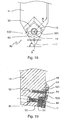
- Figures nn. 18 and 19 show a fourth locking tool 80 (ref. 80, fig. 18 ) in accordance with this invention, equipped with two wedged shaped surfaces 15 (ref. 15, fig. 18 ) and 16 (ref. 16, fig. 19 ).
- Tool 80 (ref. 80, fig. 18 ) supports triangular shaped insert ISO 1" (ref. 1", fig. 18-19 ).
- Insert 1" (ref. 1", fig. 18-19 ) is put between a centring head 51 (ref. 51, fig. 19 ) and a wedge shaped bracket 53 (ref. 53, fig. 18-19 ).
- Centring head 51 (ref. 51, fig. 19 ) and wedge shaped bracket 53 (ref. 53, fig. 18-19 ) are different shaped in comparison with head and bracket shown on figures nn. 14-17.
- centring head 51 (ref. 51, fig. 19 ) is screwed in tool 80's part 11 (ref. 80, fig. 18 and ref. 11, fig. 18 ) by a screw 81 (ref. 81, fig. 19 and ref. 11, fig. 19 ) put in a cavity obtained in part 11 (ref. 11, fig. 19 ), opposite side in comparison with supporting surface 12 (ref. 12, fig. 19 ).
- the screw 81 (ref. 81, fig. 19 ) also supports a centring pivot 82 (ref. 82, fig. 19 ) revolvingly binding centring cavity of insert 1" (ref. 1", fig. 19 ).
- the wedge shaped bracket 53 (ref. 53, fig. 18-19 ) is also screwed in tool 80's part 11 (ref. 80, fig. 18 and ref. 11, fig. 1 ) by the screw 54 (ref. 54, fig. 19 ) and has ledge surfaces 531 (ref. 531, fig. 18-19 ) and 532 (ref. 532, fig. 18 ) respectively against wedge shaped surfaces 15 (ref. 15, fig. 18 ) and 16 (ref. 16, fig. 19 ).
- the bracket 53 (ref. 53, fig. 18-19 ) is moulded to locking insert 1" (ref. 1", fig. 18-19 ), or a different insert, for example insert 1 (ref. 1, fig. 1 ), on tool 80 (ref. 80, fig. 18 ) with desired cutting angle.
- Work surface 533 (ref. 533, fig. 19 ) prevents insert 1" (ref. 1", fig. 19 ) from revolving during turning.
- inserts 1 when it wants modifying cutting angle of inserts 1 (ref. 1, fig. 1 ), 1" (ref. 2, fig. 2 ), etc. placed on tool 80 (ref. 80, fig. 19 ), it's enough unscrewing bracket 53 (ref. 53, fig. 19 ) from tool's part 11 (ref. 1, fig. 19 ) and releasing insert from surface 533's action (ref. 11, fig. 19 ). Then, inserts 1, 1", etc. (ref. 1, fig. 1 and ref. 1", fig. 19 ) can be revolved on centring pivot 82 (ref. 82, fig. 19 ), for example to use a new side-cutting edge, or to modify cutting angle already used.
- centring pivot 82 ref. 82, fig. 19
- locking tool in accordance with this invention is equipped with at least a wedge shaped surface for supporting of bracket and/or cutting insert in accordance with desired angle.
- tool is equipped with two or three wedge shaped surfaces.
- this surface can be arched, or rather can extended with a bend radius from tool's centring pivot, or from tool's extremity, etc..
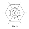
- Figure n. 20 shows an insert 200 suitable for using with locking tool in accordance with this invention, or with a traditional locking tool.
- Insert 200 gains advantage from hexagonal shape and, therefore, from having more side-cutting edges in comparison with inserts available on the market. Sides curved towards hexagon centre, in accordance with this invention, can feature insert 200.
Landscapes
- Engineering & Computer Science (AREA)
- Mechanical Engineering (AREA)
- Cutting Tools, Boring Holders, And Turrets (AREA)
- Walking Sticks, Umbrellas, And Fans (AREA)
Applications Claiming Priority (1)
| Application Number | Priority Date | Filing Date | Title |
|---|---|---|---|
| IT002124A ITMI20062124A1 (it) | 2006-11-07 | 2006-11-07 | Inserto per tornitura e relativo utensile di bloccaggio |
Publications (2)
| Publication Number | Publication Date |
|---|---|
| EP1920862A2 true EP1920862A2 (fr) | 2008-05-14 |
| EP1920862A3 EP1920862A3 (fr) | 2009-09-30 |
Family
ID=39144551
Family Applications (1)
| Application Number | Title | Priority Date | Filing Date |
|---|---|---|---|
| EP07425693A Withdrawn EP1920862A3 (fr) | 2006-11-07 | 2007-11-02 | Plaquette de coupe et porte-outil |
Country Status (2)
| Country | Link |
|---|---|
| EP (1) | EP1920862A3 (fr) |
| IT (1) | ITMI20062124A1 (fr) |
Cited By (5)
| Publication number | Priority date | Publication date | Assignee | Title |
|---|---|---|---|---|
| EP2277645A1 (fr) * | 2009-07-22 | 2011-01-26 | AS Gbr | Plaque de coupe tournante |
| KR101425710B1 (ko) * | 2012-05-04 | 2014-07-31 | 한국야금 주식회사 | 절삭 인서트 |
| US9925594B2 (en) | 2015-10-09 | 2018-03-27 | Sandvik Intellectual Property | Method to machine a metal work piece by turning |
| WO2021130741A1 (fr) * | 2019-12-26 | 2021-07-01 | Iscar Ltd. | Adaptateur d'insert de coupe et ensemble outil |
| US11273499B2 (en) | 2015-10-09 | 2022-03-15 | Sandvik Intellectual Property Ab | Turning insert |
Citations (12)
| Publication number | Priority date | Publication date | Assignee | Title |
|---|---|---|---|---|
| FR2246341A1 (en) * | 1973-10-05 | 1975-05-02 | Safety Ets | Multi-purpose cutter for a machine tool - rotary cutting insert support is locked against turning by a pin |
| GB2081142A (en) * | 1980-08-04 | 1982-02-17 | Wimet Ltd | Profiling Insert and Holder |
| FR2506642A1 (fr) * | 1981-05-29 | 1982-12-03 | Garih Claude | Outil de tour a plaquette de coupe amovible orientable |
| DE3303058A1 (de) * | 1983-01-29 | 1984-08-02 | Eugen 7250 Leonberg Hausch | Einrichtung an drehmaschinen zur lagerung eines drehstahl-einsatzes |
| DE3818970C1 (fr) * | 1988-06-03 | 1989-11-30 | Fa. Otto Steck, 7022 Leinfelden-Echterdingen, De | |
| US5503509A (en) * | 1991-08-08 | 1996-04-02 | Widia Gmbh | Cutting insert and drilling tool for drilling in solid materials |
| DE19635490A1 (de) * | 1996-09-02 | 1998-03-05 | Oehler Maschbau Gmbh | Fräswerkzeug zum Fräsen von Fasen |
| WO1998047654A1 (fr) * | 1997-04-22 | 1998-10-29 | Kennametal Inc. | Porte-outil de chanfreinage a angle d'attaque reglable |
| US6152658A (en) * | 1998-03-16 | 2000-11-28 | Iscar Ltd. | Modular cutting tool assembly |
| US6527485B1 (en) * | 2000-11-22 | 2003-03-04 | Tooling Specialties, Inc. | Threading apparatus |
| WO2004060595A1 (fr) * | 2003-01-05 | 2004-07-22 | Iscar Ltd. | Support d'element encastre coupant |
| WO2008062825A1 (fr) * | 2006-11-22 | 2008-05-29 | Mitsubishi Materials Corporation | Outil de découpe du type à insert détachable et insert |
-
2006
- 2006-11-07 IT IT002124A patent/ITMI20062124A1/it unknown
-
2007
- 2007-11-02 EP EP07425693A patent/EP1920862A3/fr not_active Withdrawn
Patent Citations (12)
| Publication number | Priority date | Publication date | Assignee | Title |
|---|---|---|---|---|
| FR2246341A1 (en) * | 1973-10-05 | 1975-05-02 | Safety Ets | Multi-purpose cutter for a machine tool - rotary cutting insert support is locked against turning by a pin |
| GB2081142A (en) * | 1980-08-04 | 1982-02-17 | Wimet Ltd | Profiling Insert and Holder |
| FR2506642A1 (fr) * | 1981-05-29 | 1982-12-03 | Garih Claude | Outil de tour a plaquette de coupe amovible orientable |
| DE3303058A1 (de) * | 1983-01-29 | 1984-08-02 | Eugen 7250 Leonberg Hausch | Einrichtung an drehmaschinen zur lagerung eines drehstahl-einsatzes |
| DE3818970C1 (fr) * | 1988-06-03 | 1989-11-30 | Fa. Otto Steck, 7022 Leinfelden-Echterdingen, De | |
| US5503509A (en) * | 1991-08-08 | 1996-04-02 | Widia Gmbh | Cutting insert and drilling tool for drilling in solid materials |
| DE19635490A1 (de) * | 1996-09-02 | 1998-03-05 | Oehler Maschbau Gmbh | Fräswerkzeug zum Fräsen von Fasen |
| WO1998047654A1 (fr) * | 1997-04-22 | 1998-10-29 | Kennametal Inc. | Porte-outil de chanfreinage a angle d'attaque reglable |
| US6152658A (en) * | 1998-03-16 | 2000-11-28 | Iscar Ltd. | Modular cutting tool assembly |
| US6527485B1 (en) * | 2000-11-22 | 2003-03-04 | Tooling Specialties, Inc. | Threading apparatus |
| WO2004060595A1 (fr) * | 2003-01-05 | 2004-07-22 | Iscar Ltd. | Support d'element encastre coupant |
| WO2008062825A1 (fr) * | 2006-11-22 | 2008-05-29 | Mitsubishi Materials Corporation | Outil de découpe du type à insert détachable et insert |
Cited By (6)
| Publication number | Priority date | Publication date | Assignee | Title |
|---|---|---|---|---|
| EP2277645A1 (fr) * | 2009-07-22 | 2011-01-26 | AS Gbr | Plaque de coupe tournante |
| KR101425710B1 (ko) * | 2012-05-04 | 2014-07-31 | 한국야금 주식회사 | 절삭 인서트 |
| US9925594B2 (en) | 2015-10-09 | 2018-03-27 | Sandvik Intellectual Property | Method to machine a metal work piece by turning |
| US11273499B2 (en) | 2015-10-09 | 2022-03-15 | Sandvik Intellectual Property Ab | Turning insert |
| WO2021130741A1 (fr) * | 2019-12-26 | 2021-07-01 | Iscar Ltd. | Adaptateur d'insert de coupe et ensemble outil |
| US11701719B2 (en) | 2019-12-26 | 2023-07-18 | Iscar, Ltd. | Cutting insert adaptor and tool assembly |
Also Published As
| Publication number | Publication date |
|---|---|
| EP1920862A3 (fr) | 2009-09-30 |
| ITMI20062124A1 (it) | 2008-05-08 |
Similar Documents
| Publication | Publication Date | Title |
|---|---|---|
| EP1349689B1 (fr) | Outil et porte-outil pour machine a former des copeaux | |
| EP1296791B1 (fr) | Outil rotatif comportant une pointe interchangeable au niveau de l'extremite libre d'enlevement de copeaux de l'outil | |
| CN1125696C (zh) | 刀夹和用于固定切削刀片的压板 | |
| KR101642525B1 (ko) | 칩 제거 가공용 회전 공구 및 이 회전 공구를 위한 루즈 탑 및 기본 몸체 | |
| RU2524290C2 (ru) | Двусторонняя режущая пластина для сверла | |
| US4743144A (en) | Face milling cutting tool | |
| EP1920862A2 (fr) | Plaquette de coupe et porte-outil | |
| US5004379A (en) | Threading insert | |
| US7320566B2 (en) | Cutting tool including detachable cutter head | |
| JP2007223041A (ja) | 着脱可能頂部を備えたエンドミル | |
| KR20000068391A (ko) | 2개의 공구 부품 결합용 공구 커플링 및 그 방법 | |
| JP5568306B2 (ja) | モジュール式穴あけ工具およびその製作方法 | |
| MXPA01008852A (es) | Fresa para ranurar y taladrar. | |
| KR20070046189A (ko) | 절삭공구 및 축방향 및 반경방향 스톱면을 구비한 헤드 | |
| EP2386374A1 (fr) | Plaque de coupe amovible, porte de plaques et outil de fraisage | |
| WO2002034441A1 (fr) | Outil pivotant dont l'extremite libre d'enlevement de copeaux est pourvue d'une partie active remplaçable | |
| JP7179096B2 (ja) | 両面接線フライス切削インサート | |
| CZ20012280A3 (cs) | Nástroj a řezná hlava pro třískové obrábění | |
| CA2736027C (fr) | Decoupeur lateral | |
| US5779400A (en) | Small-shank tool for automatic lathes | |
| US20080118313A1 (en) | Milling insert and a milling insert tool for chip removing machining | |
| US4984943A (en) | Drill with balanced inserts | |
| EP0439317B1 (fr) | Plaquette à fileter | |
| CN218696037U (zh) | 一种数控车床的刀具锁紧机构 | |
| EP3338930B1 (fr) | Plaquette de coupe pour fraise à bout sphérique, corps d'outil de fraise à bout sphérique et fraise à bout sphérique |
Legal Events
| Date | Code | Title | Description |
|---|---|---|---|
| PUAI | Public reference made under article 153(3) epc to a published international application that has entered the european phase |
Free format text: ORIGINAL CODE: 0009012 |
|
| AK | Designated contracting states |
Kind code of ref document: A2 Designated state(s): AT BE BG CH CY CZ DE DK EE ES FI FR GB GR HU IE IS IT LI LT LU LV MC MT NL PL PT RO SE SI SK TR |
|
| AX | Request for extension of the european patent |
Extension state: AL BA HR MK RS |
|
| PUAL | Search report despatched |
Free format text: ORIGINAL CODE: 0009013 |
|
| AK | Designated contracting states |
Kind code of ref document: A3 Designated state(s): AT BE BG CH CY CZ DE DK EE ES FI FR GB GR HU IE IS IT LI LT LU LV MC MT NL PL PT RO SE SI SK TR |
|
| AX | Request for extension of the european patent |
Extension state: AL BA HR MK RS |
|
| AKX | Designation fees paid |
Designated state(s): CH DE FR IT LI SE |
|
| STAA | Information on the status of an ep patent application or granted ep patent |
Free format text: STATUS: THE APPLICATION IS DEEMED TO BE WITHDRAWN |
|
| 18D | Application deemed to be withdrawn |
Effective date: 20100331 |