EP1919675B1 - Vorrichtung zum zerkleinern von lebensmitteln - Google Patents
Vorrichtung zum zerkleinern von lebensmitteln Download PDFInfo
- Publication number
- EP1919675B1 EP1919675B1 EP06776210A EP06776210A EP1919675B1 EP 1919675 B1 EP1919675 B1 EP 1919675B1 EP 06776210 A EP06776210 A EP 06776210A EP 06776210 A EP06776210 A EP 06776210A EP 1919675 B1 EP1919675 B1 EP 1919675B1
- Authority
- EP
- European Patent Office
- Prior art keywords
- housing
- locking
- plunger
- ram
- locking means
- Prior art date
- Legal status (The legal status is an assumption and is not a legal conclusion. Google has not performed a legal analysis and makes no representation as to the accuracy of the status listed.)
- Expired - Lifetime
Links
Images


Classifications
-
- B—PERFORMING OPERATIONS; TRANSPORTING
- B26—HAND CUTTING TOOLS; CUTTING; SEVERING
- B26D—CUTTING; DETAILS COMMON TO MACHINES FOR PERFORATING, PUNCHING, CUTTING-OUT, STAMPING-OUT OR SEVERING
- B26D3/00—Cutting work characterised by the nature of the cut made; Apparatus therefor
- B26D3/24—Cutting work characterised by the nature of the cut made; Apparatus therefor to obtain segments other than slices, e.g. cutting pies
- B26D3/26—Cutting work characterised by the nature of the cut made; Apparatus therefor to obtain segments other than slices, e.g. cutting pies specially adapted for cutting fruit or vegetables, e.g. for onions
Definitions
- the present invention relates to a device for mincing foodstuffs, in particular hackers, with a housing and a plunger displaceably guided in the housing and having a comminution tool.
- a device of the type mentioned is, for example, from the EP 1 027 966 A1 known.
- the housing has an additional removable lower part which sits on a shell for receiving the material to be cut.
- the device with the housing, the lower part and the shell is placed on a support.
- the plunger is inserted by hand down into the housing, wherein arranged on the plunger cutting tools cause comminution of arranged on the shell food.
- the plunger is spring biased relative to the housing so that it rests in the unactuated state at the upper end of the housing. That is, after a crushing operation by pressing down the plunger this moves automatically due to the spring bias back up and away from the material to be cut.
- the present invention is therefore based on the object, such a device for mincing food of the type mentioned in such a way and further develop that a space-saving storage and a space-saving transport are realized with simple design means.
- the above object is achieved by a device for mincing food with the features of claim 1. Thereafter, the device is configured and further developed such that the plunger can be locked in a position predeterminable relative to the housing.
- the present invention relates to a device for mincing foodstuffs, in particular hackers, with a housing and a plunger displaceably guided in the housing and having a comminution tool.
- a device of the type mentioned is, for example, from the EP 1 027 966 A1 known.
- the housing has an additional removable lower part which sits on a shell for receiving the material to be cut.
- the device with the housing, the lower part and the shell is placed on a support.
- the plunger is inserted by hand down into the housing, wherein arranged on the plunger cutting tools cause comminution of arranged on the shell food.
- the plunger is spring biased relative to the housing so that it rests in the unactuated state at the upper end of the housing. That is, after a crushing operation by pressing down the plunger this moves automatically due to the spring bias back up and away from the material to be cut.
- the present invention is therefore based on the object, a device for mincing food of the type mentioned in such a way and further, that a simplified and improved locking is possible.
- the guiding and deflecting mechanism could have a deflecting part associated with the plunger, which interacts with a corresponding swirl region of the guiding and deflecting mechanism assigned to the housing. Deflection part and swirl area cause the rotation of the plunger about the displacement axis.
- the locking means could have in a particularly simple manner at least one locking lug and / or a spring tongue.
- the locking lug and / or the spring tongue could be assigned to the deflecting part in a further structurally particularly simple manner.
- the locking means could have at least one clearance or latching recess for locking. Such clearances or recesses could then cooperate with the above-mentioned locking lugs or spring tongues for locking.
- the franking or recess which could in principle be associated with the swirl region, could be associated with a delivery or insertion bevel at the end of the swirl region of the guide and deflection mechanism. This ensures that a detent or spring tongue arrives particularly secure in the franking or recess to ensure the desired locking.
- the locking means could have a stop which could limit such a rotational movement.
- the locking means could be designed according to a ball-point locking mechanism. Any configurations are possible.
- the inventive design of a lock for the plunger in a housing of a device for mincing food does not affect the function of the device under any circumstances. Rather, the device according to the invention has an effective additional design that significantly improves the practical use of the device.
- the lock can be solved in a simple manner by an opposite rotation.
- Fig. 1 shows a sectional and schematic side view of an embodiment of a device according to the invention for comminuting food, wherein the device is formed by a hacker.
- the device comprises a housing 1 and a plunger 3 which is displaceably guided in the housing 1 and has a comminution tool 2.
- a particularly space-saving storage and with regard to a particularly space-saving transport of the plunger 3 can be locked in a position relative to the housing 1 position.
- the device is arranged on a worktop 4, this represents the usual operating position of the device.
- the plunger 3 is displaceable along a displacement axis 5 to the work surface 4, wherein the plunger 3 by means of a guide and deflecting mechanism 6 in addition to this shift still performs a superimposed rotary motion or swirling motion about the displacement axis 5.
- the guide and deflecting mechanism 6 has a plunger 3 associated deflecting part 7, which cooperates with a swirl region 11 of the guide and deflection mechanism 6.
- the swirl region 11 has a delivery or insertion bevel 10, which in a clearance 9 for a in Fig. 1 not shown spring tongue 8 of the deflecting part 7 opens.
- the housing 1 has a lower part 13 which rests on the worktop 4.
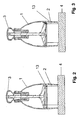
- FIGS. 2 and 3 show in schematic and sectional side views - reduced - the embodiment Fig. 1 with inserted and with the cutting tool 2 resting on the worktop 4 ram 3 and with further inserted plunger 3, so that according to Fig. 3 there is a locking of the plunger 3 in the housing 1.
- the cutting tool 2 is in the locked state slightly above the lower portion of the housing 1 and the lower part 13 also.
- Fig. 4 shows in a perspective side view of the deflecting part 7, in which case the spring tongue 8 is particularly well recognizable.
- Fig. 5 shows a schematic side view of the swirl region 11 of the guiding and deflection mechanism 6 with a recognizable attachment or insertion bevel 10 and grooves formed in the inner wall for guiding the deflection part 7.
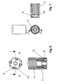
- Fig. 6 shows the component having the swirl region 11 in a plan view and in a sectional view along the line AA.
- the spring tongue 8 and a stop 12 for the spring tongue 8 can be seen in plan view.
- the deflecting part 7 is arranged in the locking position.
- the spring tongue 8 is located in the clearance 9.
- Fig. 7 shows the component having the swirl region 11 in a side view, in a bottom view and in a sectional view along the line BB.
Landscapes
- Life Sciences & Earth Sciences (AREA)
- Forests & Forestry (AREA)
- Engineering & Computer Science (AREA)
- Mechanical Engineering (AREA)
- Food-Manufacturing Devices (AREA)
- Disintegrating Or Milling (AREA)
Description
- Die vorliegende Erfindung betrifft eine Vorrichtung zum Zerkleinern von Lebensmitteln, insbesondere Hacker, mit einem Gehäuse und einem in dem Gehäuse verschiebbar geführten und ein Zerkleinerungswerkzeug aufweisenden Stößel.
- Eine Vorrichtung der eingangs genannten Art ist beispielsweise aus der
EP 1 027 966 A1 bekannt. Bei der bekannten Vorrichtung weist das Gehäuse ein zusätzliches abnehmbares Unterteil auf, das auf einer Schale zur Aufnahme des Schneidguts sitzt. Zum Zerkleinern von Lebensmitteln wird die Vorrichtung mit dem Gehäuse, dem Unterteil und der Schale auf eine Auflage aufgesetzt. Dann wird der Stößel mittels der Hand nach unten in das Gehäuse eingeschoben, wobei am Stößel angeordnete Schneidwerkzeuge eine Zerkleinerung von auf der Schale angeordneten Lebensmitteln bewirken. Der Stößel ist relativ zum Gehäuse derart federvorgespannt, dass er in unbetätigtem Zustand am oberen Ende des Gehäuses anliegt. D.h., nach einem Zerkleinerungsvorgang durch Herunterdrücken des Stößels bewegt sich dieser aufgrund der Federvorspannung selbsttätig wieder nach oben und von dem Schneidgut weg. - Bei der bekannten Vorrichtung ist problematisch, dass die Vorrichtung mit dem Gehäuse und dem oben am Gehäuse anliegenden Stößel im unbetätigten Zustand ein relativ großes Volumen einnimmt. Dies erfordert sowohl beim Transport als auch bei der Aufbewahrung der Vorrichtung ein großes Volumen oder einen großen Raum. Dies ist äußerst unpraktisch.
- Der vorliegenden Erfindung liegt daher die Aufgabe zugrunde, eine Vorrichtung zum Zerkleinern von Lebensmitteln der eingangs genannten Art derart auszugestalten und weiterzubilden, dass eine platzsparende Aufbewahrung und ein platzsparender Transport mit konstruktiv einfachen Mitteln realisiert sind.
- Erfindungsgemäß wird die voranstehende Aufgabe durch eine Vorrichtung zum Zerkleinern von Lebensmitteln mit den Merkmalen des Patentanspruches 1 gelöst. Danach ist die Vorrichtung derart ausgestaltet und weitergebildet, dass der Stößel in einer relativ zum Gehäuse vorgebbaren Position arretierbar ist.
- Die vorliegende Erfindung betrifft eine Vorrichtung zum Zerkleinern von Lebensmitteln, insbesondere Hacker, mit einem Gehäuse und einem in dem Gehäuse verschiebbar geführten und ein Zerkleinerungswerkzeug aufweisenden Stößel.
- Eine Vorrichtung der eingangs genannten Art ist beispielsweise aus der
EP 1 027 966 A1 bekannt. Bei der bekannten Vorrichtung weist das Gehäuse ein zusätzliches abnehmbares Unterteil auf, das auf einer Schale zur Aufnahme des Schneidguts sitzt. Zum Zerkleinern von Lebensmitteln wird die Vorrichtung mit dem Gehäuse, dem Unterteil und der Schale auf eine Auflage aufgesetzt. Dann wird der Stößel mittels der Hand nach unten in das Gehäuse eingeschoben, wobei am Stößel angeordnete Schneidwerkzeuge eine Zerkleinerung von auf der Schale angeordneten Lebensmitteln bewirken. Der Stößel ist relativ zum Gehäuse derart federvorgespannt, dass er in unbetätigtem Zustand am oberen Ende des Gehäuses anliegt. D.h., nach einem Zerkleinerungsvorgang durch Herunterdrücken des Stößels bewegt sich dieser aufgrund der Federvorspannung selbsttätig wieder nach oben und von dem Schneidgut weg. - Bei der bekannten Vorrichtung ist problematisch, dass die Vorrichtung mit dem Gehäuse und dem oben am Gehäuse anliegenden Stößel im unbetätigten Zustand ein relativ großes Volumen einnimmt. Dies erfordert sowohl beim Transport als auch bei der Aufbewahrung der Vorrichtung ein großes Volumen oder einen großen Raum. Dies ist äußerst unpraktisch.
- Aus
DE 197 47 007 A1 die den nächsten Stand der Technik darstellt, ist eine Schneidvorrichtung zum Zerkleinern von Nahrungsmitteln bekannt, die ein Arretierglied aufweist, mit dem der Messerträger in einer herabgedrückten Stellung arretierbar ist. - Der vorliegenden Erfindung liegt daher die Aufgabe zugrunde, eine Vorrichtung zum Zerkleinern von Lebensmitteln der eingangs genannten Art derart auszugestalten und weiterzubilden, dass ein vereinfachter und verbessertes Arretieren ermöglicht ist.
- Erfindungsgemäß wird die voranstehende Aufgabe durch eine Vorrichtung zum Zerkleinern von Lebensmitteln mit den Merkmalen des Patentanspruches 1 gelöst.
- Erfindungsgemäß ist erkannt worden, dass durch geeignete Wahl einer Arretierungsposition des Stößels relativ zum Gehäuse die obige Aufgabe auf überraachse vorzusehen. Diese auch als Drall bezeichnete Verdrehbewegung gewährleistet ein besonders effektives Zerkleinern des Schneidguts. In konstruktiv besonders einfacher und wirkungsvoller Weise könnte nun dem Gehäuse eine Führungs-und Umlenkmechanik mit Arretierungsmitteln zugeordnet sein. Diese Führung- und Umlenkmechanik, die für die Führung und Umlenkung oder Drehung des Stößels beim Einschieben des Stößels in das Gehäuse verantwortlich ist, könnte zusätzlich die Arretierung des Stößels in gewünschter Position ermöglichen.
- Im Konkreten könnte die Führungs- und Umlenkmechanik ein dem Stößel zugeordnetes Umlenkteil aufweisen, das mit einem entsprechenden, dem Gehäuse zugeordneten Drallbereich der Führungs- und Umlenkmechanik zusammenwirkt. Umlenkteil und Drallbereich bewirken das Drehen des Stößels um die Verschiebeachse.
- Die Arretierungsmittel könnten in besonders einfacher Weise mindestens eine Rastnase und/oder eine Federzunge aufweisen. Die Rastnase und/oder die Federzunge könnten in weiter konstruktiv besonders einfacher Weise dem Umlenkteil zugeordnet sein.
- Andererseits könnten die Arretierungsmittel mindestens eine Freimachung oder Rastausnehmung zum Rasten aufweisen. Derartige Freimachungen oder Rastausnehmungen könnten dann mit den oben erwähnten Rastnasen oder Federzungen zur Arretierung zusammenwirken.
- In weiter konstruktiv besonders einfacher und effektiver Weise könnte der Freimachung oder Rastausnehmung, die grundsätzlich dem Drallbereich zugeordnet sein konnten, eine An- oder Einführschräge am Ende des Drallbereichs der Führungs- und Umlenkmechanik zugeordnet sein. Hierdurch ist gewährleistet, dass eine Rastnase oder Federzunge besonders sicher in die Freimachung oder Rastausnehmung zur Gewährleistung der gewünschten Arretierung gelangt.
- Zur Begrenzung des beispielsweise durch eine Drehung erfolgenden Arretiervorgangs könnten die Arretierungsmittel einen Anschlag aufweisen, der eine derartige Drehbewegung begrenzen könnte.
- Bei Vorliegen eines Drallbereichs der Führungs- und Umlenkmechanik könnte die Arretierung also quasi durch eine Fortführung der durch den Drallbereich bewirkten Drehbewegung des Stößels über den Arbeitsbereich hinaus erfolgen. Hierdurch ist eine besonders einfache und wirkungsvolle Arretierung des Stößels relativ zum Gehäuse gewährleistet. Dabei ist maximale Platzersparnis gewährleistet.
- Bei einer konstruktiv weiter besonders einfachen Ausgestaltung könnten die Arretierungsmittel entsprechend einer Kugelschreiber-Arretiermechanik ausgebildet sein. Dabei sind beliebige Ausgestaltungen möglich.
- Es sei darauf hingewiesen, dass die erfindungsgemäße Ausgestaltung einer Arretierung für den Stößel in einem Gehäuse einer Vorrichtung zum Zerkleinern von Lebensmitteln die Funktion der Vorrichtung keinesfalls beeinträchtigt. Vielmehr weist die erfindungsgemäße Vorrichtung eine wirkungsvolle Zusatzausgestaltung auf, die den praktischen Gebrauch der Vorrichtung erheblich verbessert.
- Falls die Arretierung bei der erfindungsgemäßen Vorrichtung durch eine Drehbewegung des Stößels relativ zum Gehäuse erfolgt, kann die Arretierung auf einfache Weise durch ein gegenläufiges Drehen gelöst werden.
- Es gibt nun verschiedene Möglichkeiten, die Lehre der vorliegenden Erfindung in vorteilhafter Weise auszugestalten und weiterzubilden. Dazu ist einerseits auf die nachgeordneten Ansprüche, andererseits auf die nachfolgende Erläuterung eines Ausführungsbeispiels der erfindungsgemäßen Vorrichtung anhand der Zeichnung zu verweisen. In Verbindung mit der Erläuterung des bevorzugten Ausführungsbeispiels der erfindungsgemäßen Vorrichtung anhand der Zeichnung werden auch im Allgemeinen bevorzugte Ausgestaltungen und Weiterbildungen der Lehre erläutert. In der Zeichnung zeigen
- Fig. 1
- in einer schematischen und geschnittenen Seitenansicht ein Ausfüh- rungsbeispiel einer erfindungsgemäßen Vorrichtung zum Zerkleinern von Lebensmitteln mit maximal ausgefahrenem Stößel,
- Fig. 2
- in einer schematischen und geschnittenen Seitenansicht das Ausfüh- rungsbeispiel aus
Fig. 1 mit derart eingefahrenem Stößel, dass das Zerkleinerungswerkzeug auf einer Arbeitsplatte aufliegt, - Fig. 3
- in einer schematischen und geschnittenen Seitenansicht das Ausfüh- rungsbeispiel aus
Fig. 1 , wobei der Stößel derart über den Arbeitsbe- reich weiter hinaus eingeschoben ist, dass er in die Arretierungsposi- tion gebracht ist, - Fig. 4
- in einer perspektivischen Seitenansicht das Umlenkteil des Ausführungsbeispiels,
- Fig. 5
- in einer perspektivischen Seitenansicht den Drallbereich des Ausfüh- rungsbeispiels,
- Fig. 6
- in einer Draufsicht und in einer entlang der Linie A-A geschnittenen Seitenansicht den Drallbereich des Ausführungsbeispiels und
- Fig. 7
- in einer Seitenansicht, in einer Unteransicht sowie in einer entlang der Linie B-B geschnittenen Seitenansicht den Drallbereich des Ausfüh- rungsbeispiels.
-
Fig. 1 zeigt in einer geschnittenen und schematischen Seitenansicht ein Ausführungsbeispiel einer erfindungsgemäßen Vorrichtung zum Zerkleinern von Lebensmitteln, wobei die Vorrichtung durch einen Hacker gebildet ist. Die Vorrichtung weist ein Gehäuse 1 und einen in dem Gehäuse 1 verschiebbar geführten und ein Zerkleinerungswerkzeug 2 aufweisenden Stößel 3 auf. Im Hinblick auf eine besonders platzsparende Aufbewahrung und im Hinblick auf einen besonders platzsparenden Transport ist der Stößel 3 in einer relativ zum Gehäuse 1 vorgebbaren Position arretierbar. - Die Vorrichtung ist auf einer Arbeitsplatte 4 angeordnet, wobei dies die übliche Betriebsstellung der Vorrichtung darstellt. Der Stößel 3 ist entlang einer Verschiebeachse 5 zur Arbeitsplatte 4 hin verschiebbar, wobei der Stößel 3 mittels einer Führungs- und Umlenkmechanik 6 neben dieser Verschiebung noch eine überlagerte Drehbewegung oder Drallbewegung um die Verschiebeachse 5 ausführt.
- Die Führungs- und Umlenkmechanik 6 weist ein dem Stößel 3 zugeordnetes Umlenkteil 7 auf, das mit einem Drallbereich 11 der Führungs- und Umlenkmechanik 6 zusammenwirkt.
- Der Drallbereich 11 weist eine An- oder Einführschräge 10 auf, die in eine Freimachung 9 für eine in
Fig. 1 nicht gezeigte Federzunge 8 des Umlenkteils 7 mündet. - Des Weiteren weist das Gehäuse 1 ein Unterteil 13 auf, das auf der Arbeitsplatte 4 aufliegt.
- Die
Fig. 2 und 3 zeigen in schematischen und geschnittenen Seitenansichten - verkleinert - das Ausführungsbeispiel ausFig. 1 mit eingeschobenem und mit dem Schneidwerkzeug 2 auf der Arbeitsplatte 4 aufliegendem Stößel 3 und mit weiter eingeschobenem Stößel 3, so dass gemäßFig. 3 eine Arretierung des Stößels 3 im Gehäuse 1 vorliegt. Das Schneidwerkzeug 2 steht im arretierten Zustand geringfügig über den unteren Bereich des Gehäuses 1 bzw. das Unterteil 13 hinaus. -
Fig. 4 zeigt in einer perspektivischen Seitenansicht das Umlenkteil 7, wobei hier die Federzunge 8 besonders gut erkennbar ist. -
Fig. 5 zeigt in einer schematischen Seitenansicht den Drallbereich 11 der Führungs- und Umlenkmechanik 6 mit erkennbarer An- oder Einführschräge 10 und in der Innenwandung ausgebildeten Nuten zur Führung des Umlenkteils 7. -
Fig. 6 zeigt das den Drallbereich 11 aufweisende Bauteil in einer Draufsicht sowie in einer geschnittenen Darstellung entlang der Linie A-A. Dabei sind in der Draufsicht die Federzunge 8 und ein Anschlag 12 für die Federzunge 8 erkennbar. In der geschnittenen Darstellung ist das Umlenkteil 7 in der Arretierstellung angeordnet. Die Federzunge 8 befindet sich in der Freimachung 9. -
Fig. 7 zeigt das den Drallbereich 11 aufweisende Bauteil in einer Seitenansicht, in einer Unteransicht sowie in einer geschnittenen Darstellung entlang der Linie B-B. - Dabei sind die An- oder Einführschräge 10 sowie die Freimachung 9 des Drallbereichs 11 erkennbar.
- Beim Arretieren des Stößels 3 im Gehäuse 1 wird das Umlenkteil 7 über seinen üblichen Arbeitsbereich hinaus verschoben, so dass das Schneidwerkzeug 2 an der Unterseite des Gehäuses 1 geringfügig vorsteht. Hierdurch ist die Arretierposition gebildet.
- Hinsichtlich weiterer vorteilhafter Ausgestaltungen der erfindungsgemäßen Vorrichtung wird zur Vermeidung von Wiederholungen auf den allgemeinen Teil der Beschreibung sowie auf die beigefügten Patentansprüche verwiesen.
- Schließlich sei ausdrücklich darauf hingewiesen, dass das voranstehend beschriebene Ausführungsbeispiel der erfindungsgemäßen Vorrichtung lediglich zur Erörterung der beanspruchten Lehre dient, diese jedoch nicht auf das Ausführungsbeispiel einschränkt.
Claims (11)
- Vorrichtung zum Zerkleinern von Lebensmitteln, insbesondere Hacker, mit einem Gehäuse (1) und einem in dem Gehäuse (1) verschiebbar geführten und ein Zerkleinerungswerkzeug (2) aufweisenden Stößel (3), wobei
der Stößel (3) in einer relativ zum Gehäuse (1) vorgebbaren Position arretierbar ist, und
der Stößel (3) aus einer gegen das Gehäuse (1) vorgespannten Ruheposition in eine Arbeitsstellung verschiebbar ist dadurch gekennzeichnet, dass die Arretierung durch ein weitergehendes Verschieben des Stößels (3) über diese Arbeitsstellung hinaus erreichbar ist. - Vorrichtung nach Anspruch 1, dadurch gekennzeichnet, dass die Arretierung durch ein Drehen des Stößels (3) um die in Verschieberichtung definierte Verschiebeachse (5) des Stößels (3) realisierbar ist.
- Vorrichtung nach einem der Ansprüche 1 oder 2, dadurch gekennzeichnet, dass dem Gehäuse (1) eine Führungs- und Umlenkmechanik (6) mit Arretierungsmitteln zugeordnet ist.
- Vorrichtung nach Anspruch 3, dadurch gekennzeichnet, dass die Führungs- und Umlenkmechanik (6) ein dem Stößel (3) zugeordnetes Umlenkteil (7) aufweist.
- Vorrichtung nach Anspruch 3 oder 4, dadurch gekennzeichnet, dass die Arretierungsmittel mindestens eine Rastnase aufweisen.
- Vorrichtung nach einem der Ansprüche 3 bis 5, dadurch gekennzeichnet, dass die Arretierungsmittel eine Federzunge (8) aufweisen.
- Vorrichtung nach Anspruch 5 oder 6, dadurch gekennzeichnet, dass die Rastnase und/oder die Federzunge (8) dem Umlenkteil (7) zugeordnet sind.
- Vorrichtung nach einem der Ansprüche 3 bis 7, dadurch gekennzeichnet, dass die Arretierungsmittel mindestens eine Freimachung (9) oder Rastausnehmung zum Rasten aufweisen.
- Vorrichtung nach Anspruch 8, dadurch gekennzeichnet, dass der Freimachung (9) oder Rastausnehmung eine An- oder Einführschräge (10) am Ende eines Drallbereichs (11) der Führungs- und Umlenkmechanik (6) zugeordnet ist.
- Vorrichtung nach einem der Ansprüche 3 bis 9, dadurch gekennzeichnet, dass die Arretierungsmittel einen Anschlag (12) aufweisen.
- Vorrichtung nach einem der Ansprüche 3 bis 10, dadurch gekennzeichnet, dass die Arretierungsmittel entsprechend einer Kugelschreiber-Arretiermechanik ausgebildet sind.
Applications Claiming Priority (2)
| Application Number | Priority Date | Filing Date | Title |
|---|---|---|---|
| DE102005033778A DE102005033778A1 (de) | 2005-07-16 | 2005-07-16 | Vorrichtung zum Zerkleinern von Lebensmitteln |
| PCT/EP2006/006847 WO2007009654A1 (de) | 2005-07-16 | 2006-07-13 | Vorrichtung zum zerkleinern von lebensmitteln |
Publications (2)
| Publication Number | Publication Date |
|---|---|
| EP1919675A1 EP1919675A1 (de) | 2008-05-14 |
| EP1919675B1 true EP1919675B1 (de) | 2011-04-13 |
Family
ID=37036851
Family Applications (1)
| Application Number | Title | Priority Date | Filing Date |
|---|---|---|---|
| EP06776210A Expired - Lifetime EP1919675B1 (de) | 2005-07-16 | 2006-07-13 | Vorrichtung zum zerkleinern von lebensmitteln |
Country Status (4)
| Country | Link |
|---|---|
| EP (1) | EP1919675B1 (de) |
| AT (1) | ATE505305T1 (de) |
| DE (2) | DE102005033778A1 (de) |
| WO (1) | WO2007009654A1 (de) |
Families Citing this family (1)
| Publication number | Priority date | Publication date | Assignee | Title |
|---|---|---|---|---|
| DE102009016205B4 (de) | 2009-04-03 | 2011-06-22 | Leifheit AG, 56377 | Als Zerkleinerungsvorrichtung für Lebensmittel, Rührvorrichtung oder Schleudervorrichtung ausgebildete Vorrichtung |
Family Cites Families (2)
| Publication number | Priority date | Publication date | Assignee | Title |
|---|---|---|---|---|
| DE19747007A1 (de) * | 1997-10-24 | 1999-04-29 | Leifheit Ag | Schneidvorrichtung zum Zerkleinern von Nahrungsmitteln |
| US20050205704A1 (en) * | 2004-03-16 | 2005-09-22 | James Yurchenco | Food chopper |
-
2005
- 2005-07-16 DE DE102005033778A patent/DE102005033778A1/de not_active Withdrawn
-
2006
- 2006-07-13 AT AT06776210T patent/ATE505305T1/de active
- 2006-07-13 DE DE502006009306T patent/DE502006009306D1/de not_active Expired - Lifetime
- 2006-07-13 EP EP06776210A patent/EP1919675B1/de not_active Expired - Lifetime
- 2006-07-13 WO PCT/EP2006/006847 patent/WO2007009654A1/de not_active Ceased
Also Published As
| Publication number | Publication date |
|---|---|
| ATE505305T1 (de) | 2011-04-15 |
| EP1919675A1 (de) | 2008-05-14 |
| WO2007009654A1 (de) | 2007-01-25 |
| DE102005033778A1 (de) | 2007-01-18 |
| DE502006009306D1 (de) | 2011-05-26 |
Similar Documents
| Publication | Publication Date | Title |
|---|---|---|
| EP3347233B1 (de) | Kindersitz zur anbringung auf einem kraftfahrzeugsitz | |
| EP1491295B1 (de) | Verriegelungsbolzen zur Befestigung eines Werkzeuges an einem hydraulischen Verpressgerät | |
| DE10157238B4 (de) | Klappmesser | |
| EP2208566B1 (de) | Schneidwerkzeug mit einem spanabhebenden schneidmesser und verfahren zur befestigung des schneidmessers im schneidwerkzeug | |
| EP2063060A2 (de) | Dichtung mit einer absenkbaren Dichtungsleiste und mindestens einem Auslöseelement | |
| EP3019054B1 (de) | Besteckteil mit längenveränderbarem stiel | |
| DE29716002U1 (de) | Druckkugelschreiber mit Sichtfenster und darunter angeordneter Bedruckhülse | |
| EP2014509A2 (de) | Abdeckung für einen Spalt | |
| DE29908856U1 (de) | Messer | |
| EP4486574B1 (de) | Stempel mit einer schneidvorrichtung und verfahren zur anwendung einer schneidvorrichtung | |
| DE10251813B4 (de) | In ein Kraftfahrzeug eingebautes Behältnis | |
| DE3737863C1 (en) | Sharpener for pencils with a soft lead | |
| DE102014214184A1 (de) | Längseinsteller für einen Fahrzeugsitz und Fahrzeugsitz | |
| DE102011052180A1 (de) | Mikrotom mit Drehrichtungsumkehr | |
| DE102011082964A1 (de) | Werkzeugkassette und Zerspanungswerkzeug mit einer Werkzeugkassette | |
| DE2746033C3 (de) | Bohrkopf | |
| EP3201990B1 (de) | Anschlussklemme | |
| DE102014008717A1 (de) | Mittelkonsole für ein Kraftfahrzeug und Kraftfahrzeug mit einer solchen Mittelkonsole | |
| EP1919675A1 (de) | Vorrichtung zum zerkleinern von lebensmitteln | |
| DE102006005572A1 (de) | Stanzvorrichtung | |
| DE19952039A1 (de) | Spitzer | |
| DE4440271A1 (de) | Spitzer mit verstellbarem Fassonmesser für Stifte mit weicher Mine | |
| EP1961290B1 (de) | Verriegelungsvorrichtung für Scheren | |
| DE3341180C2 (de) | Haushaltsschneidemaschine, insbesondere mit elektromotorischem Antrieb | |
| DE102018121084B3 (de) | Vorrichtung zur Verstellung einer rotierbaren Frässpindel einer Kantenfräsmaschine und Kantenfräsmaschine |
Legal Events
| Date | Code | Title | Description |
|---|---|---|---|
| PUAI | Public reference made under article 153(3) epc to a published international application that has entered the european phase |
Free format text: ORIGINAL CODE: 0009012 |
|
| 17P | Request for examination filed |
Effective date: 20080218 |
|
| AK | Designated contracting states |
Kind code of ref document: A1 Designated state(s): AT BE BG CH CY CZ DE DK EE ES FI FR GB GR HU IE IS IT LI LT LU LV MC NL PL PT RO SE SI SK TR |
|
| 17Q | First examination report despatched |
Effective date: 20090526 |
|
| GRAP | Despatch of communication of intention to grant a patent |
Free format text: ORIGINAL CODE: EPIDOSNIGR1 |
|
| GRAS | Grant fee paid |
Free format text: ORIGINAL CODE: EPIDOSNIGR3 |
|
| GRAA | (expected) grant |
Free format text: ORIGINAL CODE: 0009210 |
|
| AK | Designated contracting states |
Kind code of ref document: B1 Designated state(s): AT BE BG CH CY CZ DE DK EE ES FI FR GB GR HU IE IS IT LI LT LU LV MC NL PL PT RO SE SI SK TR |
|
| REG | Reference to a national code |
Ref country code: GB Ref legal event code: FG4D Free format text: NOT ENGLISH |
|
| REG | Reference to a national code |
Ref country code: CH Ref legal event code: EP |
|
| REG | Reference to a national code |
Ref country code: IE Ref legal event code: FG4D Free format text: LANGUAGE OF EP DOCUMENT: GERMAN |
|
| REF | Corresponds to: |
Ref document number: 502006009306 Country of ref document: DE Date of ref document: 20110526 Kind code of ref document: P |
|
| REG | Reference to a national code |
Ref country code: DE Ref legal event code: R096 Ref document number: 502006009306 Country of ref document: DE Effective date: 20110526 |
|
| REG | Reference to a national code |
Ref country code: CH Ref legal event code: NV Representative=s name: ALDO ROEMPLER PATENTANWALT |
|
| REG | Reference to a national code |
Ref country code: NL Ref legal event code: VDEP Effective date: 20110413 |
|
| LTIE | Lt: invalidation of european patent or patent extension |
Effective date: 20110413 |
|
| PG25 | Lapsed in a contracting state [announced via postgrant information from national office to epo] |
Ref country code: LT Free format text: LAPSE BECAUSE OF FAILURE TO SUBMIT A TRANSLATION OF THE DESCRIPTION OR TO PAY THE FEE WITHIN THE PRESCRIBED TIME-LIMIT Effective date: 20110413 Ref country code: PT Free format text: LAPSE BECAUSE OF FAILURE TO SUBMIT A TRANSLATION OF THE DESCRIPTION OR TO PAY THE FEE WITHIN THE PRESCRIBED TIME-LIMIT Effective date: 20110816 Ref country code: SE Free format text: LAPSE BECAUSE OF FAILURE TO SUBMIT A TRANSLATION OF THE DESCRIPTION OR TO PAY THE FEE WITHIN THE PRESCRIBED TIME-LIMIT Effective date: 20110413 |
|
| REG | Reference to a national code |
Ref country code: IE Ref legal event code: FD4D |
|
| PG25 | Lapsed in a contracting state [announced via postgrant information from national office to epo] |
Ref country code: CY Free format text: LAPSE BECAUSE OF FAILURE TO SUBMIT A TRANSLATION OF THE DESCRIPTION OR TO PAY THE FEE WITHIN THE PRESCRIBED TIME-LIMIT Effective date: 20110413 Ref country code: SI Free format text: LAPSE BECAUSE OF FAILURE TO SUBMIT A TRANSLATION OF THE DESCRIPTION OR TO PAY THE FEE WITHIN THE PRESCRIBED TIME-LIMIT Effective date: 20110413 Ref country code: IS Free format text: LAPSE BECAUSE OF FAILURE TO SUBMIT A TRANSLATION OF THE DESCRIPTION OR TO PAY THE FEE WITHIN THE PRESCRIBED TIME-LIMIT Effective date: 20110813 Ref country code: ES Free format text: LAPSE BECAUSE OF FAILURE TO SUBMIT A TRANSLATION OF THE DESCRIPTION OR TO PAY THE FEE WITHIN THE PRESCRIBED TIME-LIMIT Effective date: 20110724 Ref country code: FI Free format text: LAPSE BECAUSE OF FAILURE TO SUBMIT A TRANSLATION OF THE DESCRIPTION OR TO PAY THE FEE WITHIN THE PRESCRIBED TIME-LIMIT Effective date: 20110413 Ref country code: LV Free format text: LAPSE BECAUSE OF FAILURE TO SUBMIT A TRANSLATION OF THE DESCRIPTION OR TO PAY THE FEE WITHIN THE PRESCRIBED TIME-LIMIT Effective date: 20110413 Ref country code: GR Free format text: LAPSE BECAUSE OF FAILURE TO SUBMIT A TRANSLATION OF THE DESCRIPTION OR TO PAY THE FEE WITHIN THE PRESCRIBED TIME-LIMIT Effective date: 20110714 |
|
| PG25 | Lapsed in a contracting state [announced via postgrant information from national office to epo] |
Ref country code: NL Free format text: LAPSE BECAUSE OF FAILURE TO SUBMIT A TRANSLATION OF THE DESCRIPTION OR TO PAY THE FEE WITHIN THE PRESCRIBED TIME-LIMIT Effective date: 20110413 |
|
| BERE | Be: lapsed |
Owner name: LEIFHEIT A.G. Effective date: 20110731 |
|
| PG25 | Lapsed in a contracting state [announced via postgrant information from national office to epo] |
Ref country code: IE Free format text: LAPSE BECAUSE OF FAILURE TO SUBMIT A TRANSLATION OF THE DESCRIPTION OR TO PAY THE FEE WITHIN THE PRESCRIBED TIME-LIMIT Effective date: 20110413 Ref country code: CZ Free format text: LAPSE BECAUSE OF FAILURE TO SUBMIT A TRANSLATION OF THE DESCRIPTION OR TO PAY THE FEE WITHIN THE PRESCRIBED TIME-LIMIT Effective date: 20110413 Ref country code: EE Free format text: LAPSE BECAUSE OF FAILURE TO SUBMIT A TRANSLATION OF THE DESCRIPTION OR TO PAY THE FEE WITHIN THE PRESCRIBED TIME-LIMIT Effective date: 20110413 |
|
| PLBE | No opposition filed within time limit |
Free format text: ORIGINAL CODE: 0009261 |
|
| STAA | Information on the status of an ep patent application or granted ep patent |
Free format text: STATUS: NO OPPOSITION FILED WITHIN TIME LIMIT |
|
| PG25 | Lapsed in a contracting state [announced via postgrant information from national office to epo] |
Ref country code: RO Free format text: LAPSE BECAUSE OF FAILURE TO SUBMIT A TRANSLATION OF THE DESCRIPTION OR TO PAY THE FEE WITHIN THE PRESCRIBED TIME-LIMIT Effective date: 20110413 Ref country code: SK Free format text: LAPSE BECAUSE OF FAILURE TO SUBMIT A TRANSLATION OF THE DESCRIPTION OR TO PAY THE FEE WITHIN THE PRESCRIBED TIME-LIMIT Effective date: 20110413 Ref country code: MC Free format text: LAPSE BECAUSE OF NON-PAYMENT OF DUE FEES Effective date: 20110731 Ref country code: PL Free format text: LAPSE BECAUSE OF FAILURE TO SUBMIT A TRANSLATION OF THE DESCRIPTION OR TO PAY THE FEE WITHIN THE PRESCRIBED TIME-LIMIT Effective date: 20110413 Ref country code: DK Free format text: LAPSE BECAUSE OF FAILURE TO SUBMIT A TRANSLATION OF THE DESCRIPTION OR TO PAY THE FEE WITHIN THE PRESCRIBED TIME-LIMIT Effective date: 20110413 |
|
| 26N | No opposition filed |
Effective date: 20120116 |
|
| PG25 | Lapsed in a contracting state [announced via postgrant information from national office to epo] |
Ref country code: BE Free format text: LAPSE BECAUSE OF NON-PAYMENT OF DUE FEES Effective date: 20110731 |
|
| REG | Reference to a national code |
Ref country code: DE Ref legal event code: R097 Ref document number: 502006009306 Country of ref document: DE Effective date: 20120116 |
|
| PG25 | Lapsed in a contracting state [announced via postgrant information from national office to epo] |
Ref country code: IT Free format text: LAPSE BECAUSE OF FAILURE TO SUBMIT A TRANSLATION OF THE DESCRIPTION OR TO PAY THE FEE WITHIN THE PRESCRIBED TIME-LIMIT Effective date: 20110413 |
|
| PG25 | Lapsed in a contracting state [announced via postgrant information from national office to epo] |
Ref country code: LU Free format text: LAPSE BECAUSE OF NON-PAYMENT OF DUE FEES Effective date: 20110713 |
|
| PG25 | Lapsed in a contracting state [announced via postgrant information from national office to epo] |
Ref country code: BG Free format text: LAPSE BECAUSE OF FAILURE TO SUBMIT A TRANSLATION OF THE DESCRIPTION OR TO PAY THE FEE WITHIN THE PRESCRIBED TIME-LIMIT Effective date: 20110713 |
|
| PG25 | Lapsed in a contracting state [announced via postgrant information from national office to epo] |
Ref country code: TR Free format text: LAPSE BECAUSE OF FAILURE TO SUBMIT A TRANSLATION OF THE DESCRIPTION OR TO PAY THE FEE WITHIN THE PRESCRIBED TIME-LIMIT Effective date: 20110413 |
|
| PG25 | Lapsed in a contracting state [announced via postgrant information from national office to epo] |
Ref country code: HU Free format text: LAPSE BECAUSE OF FAILURE TO SUBMIT A TRANSLATION OF THE DESCRIPTION OR TO PAY THE FEE WITHIN THE PRESCRIBED TIME-LIMIT Effective date: 20110413 |
|
| PGFP | Annual fee paid to national office [announced via postgrant information from national office to epo] |
Ref country code: GB Payment date: 20150624 Year of fee payment: 10 |
|
| PGFP | Annual fee paid to national office [announced via postgrant information from national office to epo] |
Ref country code: CH Payment date: 20150724 Year of fee payment: 10 |
|
| PGFP | Annual fee paid to national office [announced via postgrant information from national office to epo] |
Ref country code: AT Payment date: 20150624 Year of fee payment: 10 |
|
| REG | Reference to a national code |
Ref country code: FR Ref legal event code: PLFP Year of fee payment: 11 |
|
| REG | Reference to a national code |
Ref country code: CH Ref legal event code: PL |
|
| REG | Reference to a national code |
Ref country code: AT Ref legal event code: MM01 Ref document number: 505305 Country of ref document: AT Kind code of ref document: T Effective date: 20160713 |
|
| GBPC | Gb: european patent ceased through non-payment of renewal fee |
Effective date: 20160713 |
|
| PG25 | Lapsed in a contracting state [announced via postgrant information from national office to epo] |
Ref country code: LI Free format text: LAPSE BECAUSE OF NON-PAYMENT OF DUE FEES Effective date: 20160731 Ref country code: CH Free format text: LAPSE BECAUSE OF NON-PAYMENT OF DUE FEES Effective date: 20160731 |
|
| PG25 | Lapsed in a contracting state [announced via postgrant information from national office to epo] |
Ref country code: GB Free format text: LAPSE BECAUSE OF NON-PAYMENT OF DUE FEES Effective date: 20160713 Ref country code: AT Free format text: LAPSE BECAUSE OF NON-PAYMENT OF DUE FEES Effective date: 20160713 |
|
| REG | Reference to a national code |
Ref country code: FR Ref legal event code: PLFP Year of fee payment: 12 |
|
| REG | Reference to a national code |
Ref country code: FR Ref legal event code: PLFP Year of fee payment: 13 |
|
| PGFP | Annual fee paid to national office [announced via postgrant information from national office to epo] |
Ref country code: FR Payment date: 20230616 Year of fee payment: 18 |
|
| PGFP | Annual fee paid to national office [announced via postgrant information from national office to epo] |
Ref country code: DE Payment date: 20230801 Year of fee payment: 18 |
|
| REG | Reference to a national code |
Ref country code: DE Ref legal event code: R082 Ref document number: 502006009306 Country of ref document: DE Representative=s name: KBN IP PATENTANWAELTE PARTNERSCHAFT MBB, DE |
|
| REG | Reference to a national code |
Ref country code: DE Ref legal event code: R119 Ref document number: 502006009306 Country of ref document: DE |
|
| PG25 | Lapsed in a contracting state [announced via postgrant information from national office to epo] |
Ref country code: DE Free format text: LAPSE BECAUSE OF NON-PAYMENT OF DUE FEES Effective date: 20250201 |
|
| PG25 | Lapsed in a contracting state [announced via postgrant information from national office to epo] |
Ref country code: FR Free format text: LAPSE BECAUSE OF NON-PAYMENT OF DUE FEES Effective date: 20240731 |