EP1918444A2 - Laugenbehälter mit Ballastgewicht für eine Waschmaschine - Google Patents
Laugenbehälter mit Ballastgewicht für eine Waschmaschine Download PDFInfo
- Publication number
- EP1918444A2 EP1918444A2 EP07019790A EP07019790A EP1918444A2 EP 1918444 A2 EP1918444 A2 EP 1918444A2 EP 07019790 A EP07019790 A EP 07019790A EP 07019790 A EP07019790 A EP 07019790A EP 1918444 A2 EP1918444 A2 EP 1918444A2
- Authority
- EP
- European Patent Office
- Prior art keywords
- ballast weight
- opening
- container
- pin
- wall
- Prior art date
- Legal status (The legal status is an assumption and is not a legal conclusion. Google has not performed a legal analysis and makes no representation as to the accuracy of the status listed.)
- Granted
Links
Images



Classifications
-
- D—TEXTILES; PAPER
- D06—TREATMENT OF TEXTILES OR THE LIKE; LAUNDERING; FLEXIBLE MATERIALS NOT OTHERWISE PROVIDED FOR
- D06F—LAUNDERING, DRYING, IRONING, PRESSING OR FOLDING TEXTILE ARTICLES
- D06F37/00—Details specific to washing machines covered by groups D06F21/00 - D06F25/00
- D06F37/26—Casings; Tubs
- D06F37/265—Counterweights mounted to the tub; Mountings therefor
-
- D—TEXTILES; PAPER
- D06—TREATMENT OF TEXTILES OR THE LIKE; LAUNDERING; FLEXIBLE MATERIALS NOT OTHERWISE PROVIDED FOR
- D06F—LAUNDERING, DRYING, IRONING, PRESSING OR FOLDING TEXTILE ARTICLES
- D06F37/00—Details specific to washing machines covered by groups D06F21/00 - D06F25/00
- D06F37/26—Casings; Tubs
- D06F37/261—Tubs made by a specially selected manufacturing process or characterised by their assembly from elements
- D06F37/262—Tubs made by a specially selected manufacturing process or characterised by their assembly from elements made of plastic material, e.g. by injection moulding
Definitions
- the invention relates to a tub for a drum washing machine with at least one fastened by means of screw ballast weight, which is pressed onto bearing areas on the container wall, wherein for the screw on the container wall in each case a pin is formed, which projects into a corresponding opening in the ballast weight, wherein between the Spigot and the opening a circumferential cavity remains.
- Such a tub is from the DE 42 38 686 C1 known.
- dome or pin are formed on the end walls, which protrude into openings in the ballast weight.
- the domes are each provided with an axial bore into which a screw is screwed, which presses with its screw head the ballast weight against the support area.
- the opening in the ballast weight is covered with a spring plate, which provides a biasing force on the ballast weight after screwing the screw.
- a relaxation can not be avoided in the contact area, whereby the preload force gradually decreases. At higher weights or larger imbalances, the ballast weight can loosen and in the worst case solve.
- a tub in which fastening elements and domes or pins are formed on the end wall.
- the fasteners and domes protrude into corresponding recesses or openings in the ballast weight, wherein the ballast weight rests on the end wall and wherein the recesses closely surround the lateral border of the projecting fasteners.
- the weight is connected through corresponding openings by means of connecting means with the tub.
- it is necessary that the contour of the openings in the weight are carried out very accurately and with high dimensional accuracy, so that the positive connection between the opening and dome is achieved and the weight does not rattle or vibrate in operation relative to the container wall.
- ballast weight has a conical passage opening, which is slipped over a hollow pin on the tub wall.
- a conical or wedge-shaped part is inserted in the hollow pin, which the walls of the pin outwardly against the inner periphery of the passage opening of the Ballast weight presses. Due to the spreading apart of the walls, which then nestle against the conical passage opening, the ballast weight is fixed to the container wall. Since the plastic material of the pin bears against the ballast weight under pressure, it may deform slightly due to relaxation phenomena, as a result of which the pressure against the inner wall of the through hole decreases. Due to the decreasing pressure, the ballast weight can loosen slightly, which can cause heavy rattling of the tub rattling or in the worst case to release the ballast weight.
- the invention is therefore based on the object to provide a plastic tub with an improved attachment for at least one ballast weight.
- a circumferential, elastic element is used, which at least partially fills the cavity.
- a permanent and safe installation of the ballast weight is at least partially provided on the outer circumference of the pin, whereby possible relative movements between ballast weight and suds tank wall are avoided.
- a large biasing force is no longer necessary, whereby the container wall is not heavily loaded in the support area.
- the service life is increased and possible cracks due to excessive stresses or strains are avoided.
- the elastic element is designed as a sleeve which rests with its substantially flat jacket portion on the inner wall of the opening of the ballast weight and on the side remote from the container wall has a circumferential, outwardly directed collar as a support for the screw.
- the screw acts with the interposition of the likewise elastic collar on the ballast weight, whereby a limited, uniform pressure on the ballast weight and in the region of the support on the container wall is achieved.
- the sleeve has on the front wall facing the container wall another circumferential, outwardly directed collar, which is located between ballast weight and container wall and provides the support for the ballast weight.
- this intermediate layer an increased frictional resistance between the ballast weight and the container wall is achieved, whereby lateral relative movements of the ballast weight are avoided for all occurring operating situations over the entire life of the washing machine.
- the sleeve consists of an elastomer or rubber material which has a hardness in the range between 40 to 80 ShoreA. With this hardness, a limited deformability is achieved, whereby at least partially a positive connection with the pin and / or the opening in the ballast weight is provided.
- the material-related, high frictional resistance in the support area also ensures good adhesion.
- the material for a stable attachment is hard enough so that no possible relative movements of the ballast weight occur.
- At least one fastening tab is integrally formed on an end wall of the tub, on which the fastening pin extends from the plane of the end wall pioneering.
- the attachment can be performed regardless of the circumstances of the container wall.
- the fastening strap can be made with a higher material thickness to better withstand the stresses.
- a nut is arranged on the fastening tab, in which the screw is screwed.
- the screw is screwed.
- a circumferential shoulder is arranged, on which rests the circumferential collar of the elastic sleeve, wherein a disc is arranged between the screw and the collar is who presses the collar on the heel.
- the disk for receiving the screw in the central region has an elongated opening which allows a displacement of the position for the screw.
- the ballast weight can be displaced laterally before attachment to a limited extent relative to the container wall, whereby manufacturing tolerances are compensated.
- ballast weight circular arc When attaching the ballast weight on the front side of the layer container, it is expedient to perform the ballast weight circular arc.
- a washing machine 8 is sketched with a tub 1 in a side view as a section.
- the tub 1 consists at least of a cylindrical shell 2, which surrounds a drum 3.
- the cylindrical shell 2 is closed by at least one rear bottom wall 6a.
- a hub 4 is integrated, which receives the drive shaft 5 for driven by a motor 12 drum 3.
- the front end wall 6, which is also referred to as a lye container cap, is provided with a loading opening 7, which can be closed by a door 9.
- Ballastmonye 10, 11 are attached.
- the tub 1 is shown in a perspective view from the front. This view corresponds to the operational position of the tub.
- the ballast weights 11 are arranged on the outside of the front end wall 6, wherein they are arcuately formed as a ring segment and the outside approximately follow the course of the shell 2 and inside the loading opening 7 keep clear.
- the weights 11 are fastened with screws 13 on the end wall 6, wherein in this case the attachment to fastening tabs 14 takes place, which are integrally formed on the end wall 6 and / or on the jacket 2.
- the upper weight 11 is sketched without screws, so that the openings 16, 16a, 16b can be seen.
- the openings 16, 16a are arranged at the outer, lateral ends.
- the opening 16 b is arranged in the region of the apex 27 of the arcuate ballast weight 11.
- Fig. 3 the attachment of the ballast weight 11 is sketched in detail.
- a pin 15 (not shown) integrally formed, which rises from the plane of the tab 14.
- the ballast weight 11 has an opening 16 into which the pin 15 projects from the wall side. With the help of the screw 13 and an underlaid disc 21, the ballast weight 11 is pressed against the container wall 6 and the tab 14.
- the opening 16 is dimensioned so that it surrounds the pin 15 (not shown) to form a cavity.
- the opening 26 in the attached disc 21 is elongated, and thus provides a tolerance compensation for the screw fastening.
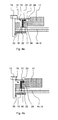
- Fig. 4a the fixed ballast weight 11 is sketched in a detailed sectional view.
- the ballast weight 11 is pressed against the contact area 17 on the container wall 6 and on the tab 14.
- the pin 15 rises, which projects into the opening 16 of the ballast weight 11.
- the elastic sleeve 19 is located in the cavity 18 on the inner wall 28 of the opening 16, wherein the cavity 18 between the pin 15 and the inner wall 28 of the opening 16 is only partially filled by the sleeve 19.
- a circumferential collar 23 is formed, which is directed radially outward and rests on a peripheral shoulder 24 of the ballast weight 11.
- the flat portion 22 of the ring 19 is slightly compressed and pressed the circumferential collar 23 on the ballast weight 11 and on the shoulder 24. Due to the resilience of the collar 23, the ballast weight 11 is pressed with a limited force against the contact area 17 on the container wall 6 and tab 14, whereby a reliable and permanent tight fit of the ballast weight 11 is achieved.
- Fig. 4b shows the ballast weight 11 in a sketched sectional view in another position.
- the cavity 18 between the pin 15 and the inner wall 28 of the opening 16 is almost completely filled, wherein the flat portion 22 of the elastic ring 19 abuts both the pin 15 and on the inner wall 28 of the opening 16 and within the Cavity 18 is compressed.
- Fig. 5 shows an embodiment of the sleeve 19, in which on the end facing the container wall 6, a further circumferential, outwardly directed collar 25 is formed, which is located between the ballast weight 11 and container wall 6 and the support 17 provides for the ballast weight 11.
- This collar 25 causes an intermediate friction increased resistance between ballast weight 11 and container wall 6, whereby lateral relative movements of the ballast weight 11 can be avoided. Due to the increased frictional resistance of the collar 25 of the interference fit is further improved, the ballast weight 11 does not have to be pressed so firmly against the end face 17 of the pin 15. As a result, the relaxation behavior in the plastic in the attachment or the support 17 is largely avoided. This provides a reliable attachment for all operating situations that occur over the entire service life of the washing machine 8 (FIG. 1).
- FIG. 6 shows a further embodiment in which the nut 20 comprises segments 30 which are angled toward the tab 14 and which are partially passed through openings 29 in the tab 14. The free end of these segments 30 forms the support 17 for the ballast weight 11. With this fastening, the screw 13 can be very tightened because the ballast weight 11 is no longer pressed with its support portion 17 on the plastic of the container wall 6 and the tab 14 and therefore can not eat into the plastic.
Landscapes
- Engineering & Computer Science (AREA)
- Textile Engineering (AREA)
- Main Body Construction Of Washing Machines And Laundry Dryers (AREA)
Abstract
Description
- Die Erfindung betrifft einen Laugenbehälter für eine Trommelwaschmaschine mit zumindest einem mittels Schraubverbindung befestigten Ballastgewicht, welches auf Auflagebereiche an der Behälterwand angedrückt wird, wobei für die Schraubverbindung an der Behälterwand jeweils ein Zapfen angeformt ist, der in eine korrespondierende Öffnung im Ballastgewicht ragt, wobei zwischen dem Zapfen und der Öffnung ein umlaufender Hohlraum verbleibt.
- Ein derartiger Laugenbehälter ist aus der
DE 42 38 686 C1 bekannt. Bei diesem Laugenbehälter sind an den Stirnwänden Dome bzw. Zapfen angeformt, die in Öffnungen im Ballastgewicht ragen. Die Dome sind jeweils mit einer axialen Bohrung versehen, in die eine Schraube eingeschraubt wird, die mit ihrem Schraubenkopf das Ballastgewicht gegen den Auflagebereich drückt. Als Auflagebereich sind um die Dome umlaufende Rippen angeformt. Die Öffnung im Ballastgewicht wird mit einem Federteller überdeckt, der nach dem Einschrauben der Schraube eine Vorspannkraft auf das Ballastgewicht bereitstellt. Bei einem Laugenbehälter aus Kunststoff ist im Auflagebereich eine Relaxion nicht zu vermeiden, wodurch die Vorspannkraft allmählich nachlässt. Bei höheren Gewichten oder größeren Unwuchten kann sich das Ballastgewicht lockern und im schlimmsten Fall lösen. - Aus der
DE 102 15 254 A1 ist ein Laugenbehälter bekannt, bei dem auf der Stirnwand Befestigungselemente und Dome oder Zapfen angeformt sind. Die Befestigungselemente und Dome ragen in korrespondierende Einbuchtungen bzw. Öffnungen im Ballastgewicht, wobei das Ballastgewicht auf der Stirnwand aufliegt und wobei die Einbuchtungen die seitliche Umrandung der vorspringenden Befestigungselemente eng umschließen. Von der Außenseite her wird das Gewicht durch entsprechende Öffnungen mit Hilfe von Verbindungsmitteln mit dem Laugenbehälter verbunden. Bei dieser Art der Befestigung ist es jedoch notwendig, dass die Kontur der Öffnungen im Gewicht sehr genau und mit hoher Maßhaltigkeit ausgeführt werden, damit die formschlüssige Verbindung zwischen Öffnung und Dom erreicht wird und das Gewicht im Betrieb gegenüber der Behälterwand nicht klappert oder vibriert. - Aus der
EP 0 798 412 A2 ist es bekannt, ein Ballastgewicht an einen Laugenbehälter aus Kunststoff mittels Spreizdübel zu befestigen. Hierbei hat das Ballastgewicht eine konische Durchgangsöffnung, die über einen hohlen Zapfen an der Laugenbehälterwand gestülpt wird. In den hohlen Zapfen wird wiederum ein kegel- oder keilförmiges Teil eingefügt, welches die Wandungen des Zapfens nach außen gegen den Innenumfang der Durchgangsöffnung des Ballastgewichts drückt. Durch das Auseinanderspreizen der Wandungen, die sich dann an die konische Durchgangsöffnung anschmiegen, wird das Ballastgewicht an der Behälterwand fixiert. Da das Kunststoffmaterial des Zapfens unter Druck am Ballastgewicht anliegt, kann es sich aufgrund von Relaxionserscheinungen etwas verformen, wodurch der Druck gegen die Innenwandung der Durchgangsöffnung nachlässt. Durch den nachlassenden Druck kann sich das Ballastgewicht etwas lockern, wodurch es bei starken Bewegungen des Laugenbehälters zum Klappern oder im schlimmsten Fall zum Lösen des Ballastgewichtes kommen kann. - Der Erfindung liegt somit die Aufgabe zugrunde, einen Kunststoff-Laugenbehälter mit einer verbesserten Befestigung für zumindest ein Ballastgewicht bereitzustellen.
- Erfindungsgemäß wird die Aufgabe mit den Merkmalen des Anspruchs 1 gelöst. Vorteilhafte Ausgestaltungen und Weiterbildungen der Erfindung ergeben sich aus den nachfolgenden abhängigen Ansprüchen.
- Hierzu wird gemäß der Erfindung vorgeschlagen, dass im Hohlraum zwischen Zapfen und Öffnung ein umlaufendes, elastisches Element eingesetzt ist, welches den Hohlraum zumindest bereichsweise ausfüllt. Dadurch wird eine dauerhafte und sichere Anlage des Ballastgewichts an den Außenumfang des Zapfens zumindest bereichsweise bereitgestellt, wodurch mögliche Relativbewegungen zwischen Ballastgewicht und Laugenbehälterwand vermieden werden. Für die Befestigung ist eine große Vorspannkraft nicht mehr notwendig, wodurch die Behälterwand im Auflagebereich nicht stark belastet wird. Dadurch wird die Lebensdauer erhöht und mögliche Risse aufgrund zu starker Spannungen oder Belastungen werden vermieden.
- In einer zweckmäßigen Ausführung ist das elastische Element als Hülse ausgeführt, die mit ihrem im wesentlichen ebenen Mantelbereich an der Innenwand der Öffnung des Ballastgewichts anliegt und auf der von der Behälterwand abgewandten Seite einen umlaufenden, nach außen gerichteten Kragen als Auflage für die Schraubverbindung besitzt. Hierdurch wirkt die Schraube unter Zwischenlage des ebenfalls elastischen Kragens auf das Ballastgewicht, wodurch ein begrenzter, gleichmäßiger Andruck auf das Ballastgewicht und im Bereich der Auflage an der Behälterwand erreicht wird.
- In einer vorteilhaften Weiterbildung besitzt die Hülse auf der zur Behälterwand zugewandten Stirnseite einen weiteren umlaufenden, nach außen gerichteten Kragen, der sich zwischen Ballastgewicht und Behälterwand befindet und die Auflage für das Ballastgewicht bereitstellt. Mit dieser Zwischenlage wird ein erhöhter Reibungswiderstand zwischen Ballastgewicht und Behälterwand erreicht, wodurch seitliche Relativbewegungen des Ballastgewichts für alle auftretenden Betriebssituationen über die gesamte Lebensdauer der Waschmaschine vermieden werden.
- In einer zweckmäßigen Ausführung besteht die Hülse aus einem Elastomer- oder Gummimaterial, welches eine Härte im Bereich zwischen 40 bis 80 ShoreA besitzt. Mit dieser Härte wird eine begrenzte Verformbarkeit erreicht, wodurch zumindest bereichsweise ein Formschluss mit dem Zapfen und/oder der Öffnung im Ballastgewicht bereitgestellt wird. Außerdem sorgt der materialbedingte, hohe Reibwiderstand im Auflagebereich zusätzlich für einen guten Kraftschluss. Andererseits ist das Material für eine stabile Befestigung hart genug, damit möglichst keine Relativbewegungen des Ballastgewichts auftreten.
- In einer weiteren vorteilhaften Ausführungsform ist an einer Stirnwand des Laugenbehälters zumindest eine Befestigungslasche angeformt, an dem sich der Befestigungszapfen von der Ebene der Stirnwand wegweisend erstreckt. Hierbei kann die Befestigung unabhängig von den Gegebenheiten der Behälterwand ausgeführt werden. Insbesondere kann die Befestigungslasche mit einer höheren Materialstärke ausgeführt werden, um den Belastungen noch besser stand zu halten.
- In einer zweckmäßigen Weiterbildung ist an der Befestigungslasche eine Mutter angeordnet, in welche die Schraube eingeschraubt ist. Damit wird eine feste Verschraubung erreicht, wobei im Kunststoffmaterial Gewindeeinformungen oder Verspannungen durch selbstschneidende Schrauben vermieden werden.
- Um eine verbesserte Führung der elastischen Hülse im Bereich der Befestigung bereitzustellen, ist in einer zweckmäßigen Ausführung um die zumindest eine Öffnung im Ballastgewicht ein umlaufender Absatz angeordnet, auf den der umlaufende Kragen der elastischen Hülse aufliegt, wobei zwischen der Schraube und dem Kragen eine Scheibe angeordnet ist, die den Kragen auf den Absatz drückt.
- In einer vorteilhaften Ausführung besitzt die Scheibe zur Aufnahme der Schraube im mittleren Bereich eine längliche Öffnung, die eine Verschiebung der Position für die Schraube erlaubt. Hierdurch kann das Ballastgewicht vor dem Befestigen in begrenztem Maße gegenüber der Behälterwand seitlich verschoben werden, wodurch Fertigungstoleranzen ausgeglichen werden.
- Bei der Befestigung des Ballastgewichts an der Stirnseite des Lagenbehälters ist es zweckmäßig, das Ballastgewicht kreisbogenförmig auszuführen. In dieser Ausführung ist es vorteilhaft, zumindest an den äußeren Enden jeweils eine Öffnung und im Bereich des Scheitels eine Öffnung für die Befestigung an der Behälterwand vorzusehen.
- Ein Ausführungsbeispiel der Erfindung wird an Hand der nachstehenden Figuren näher erläutert, dabei zeigen:
- Fig. 1:
- eine Skizze einer Trommelwaschmaschine;
- Fig. 2:
- den Laugenbehälter in einer perspektivischen Frontansicht;
- Fig. 3:
- einen Ausschnitt der Befestigung des Ballastgewichts;
- Fig. 4a, 4b:
- einen Ausschnitt der Befestigung des Ballastgewichts in einer Schnittdarstellung und
- Fig. 5, 6
- weitere Ausführungsformen in einer detaillierten Schnittdarstellung.
- In Fig. 1 ist eine Waschmaschine 8 mit einem Laugenbehälter 1 in einer Seitenansicht als Schnitt skizziert. Der Laugenbehälter 1 besteht zumindest aus einem zylindrischen Mantel 2, der eine Trommel 3 umgibt. Der zylindrische Mantel 2 wird durch zumindest eine hintere Bodenwand 6a geschlossen. In der Bodenwand 6a ist eine Nabe 4 eingebunden, welche die Antriebswelle 5 für die mittels eines Motors 12 angetriebene Trommel 3 aufnimmt. Die vordere Stirnwand 6, die auch als Laugenbehälterkappe bezeichnet wird, ist mit einer Beladungsöffnung 7 versehen, die durch eine Tür 9 verschließbar ist. Am Mantel 2 und/oder an der Stirnwand 6 sind Ballastgewichte 10, 11 befestigt.
- In Fig. 2 ist der Laugenbehälter 1 in einer perspektivischen Ansicht von vorn dargestellt. Diese Ansicht entspricht der betriebsgemäßen Lage des Laugenbehälters. Die Ballastgewichte 11 sind außenseitig an der vorderen Stirnwand 6 angeordnet, wobei sie bogenförmig als Ringsegment ausgebildet sind und außenseitig in etwa dem Verlauf des Mantels 2 folgen und innenseitig die Beladungsöffnung 7 freihalten. Die Gewichte 11 sind mit Schrauben 13 an der Stirnwand 6 befestigt, wobei hierbei die Befestigung an Befestigungslaschen 14 erfolgt, die an der Stirnwand 6 und/oder am Mantel 2 angeformt sind. Das obere Gewicht 11 ist ohne Schrauben aufskizziert, damit die Öffnungen 16, 16a, 16b zu erkennen sind. Die Öffnungen 16, 16a sind an den äußeren, seitlichen Enden angeordnet. Die Öffnung 16b ist im Bereich des Scheitels 27 des bogenförmigen Ballastgewichts 11 angeordnet.
- In Fig. 3 ist die Befestigung des Ballastgewichts 11 im Detail aufskizziert. An der Stirnwand 6 bzw. an der Lasche 14 ist ein Zapfen 15 (nicht dargestellt) angeformt, der sich aus der Ebene der Lasche 14 erhebt. Das Ballastgewicht 11 hat eine Öffnung 16, in die von der Wandseite her der Zapfen 15 hineinragt. Mit Hilfe der Schraube 13 und einer untergelegten Scheibe 21 wird das Ballastgewicht 11 gegen die Behälterwand 6 bzw. die Lasche 14 gedrückt. Die Öffnung 16 ist dabei so bemessen, dass sie den Zapfen 15 (nicht dargestellt) unter Bildung eines Hohlraumes umgibt. Die Öffnung 26 in der aufgesetzten Scheibe 21 ist länglich ausgebildet, und stellt damit einen Toleranzausgleich für die Schraubbefestigung bereit.
- In Fig. 4a ist das befestigte Ballastgewicht 11 in einer detaillierten Schnittdarstellung aufskizziert. Durch das Anziehen der Schraube 13, die in einer Mutter 20 auf der gegenüberliegenden Seite der Lasche 14 eingeschraubt wird, wird das Ballastgewicht 11 gegen den Anlagebereich 17 an der Behälterwand 6 bzw. an der Lasche 14 gedrückt. Aus der Ebene der Lasche 14 erhebt sich der Zapfen 15, der in die Öffnung 16 des Ballastgewichts 11 ragt. Die elastische Hülse 19 liegt im Hohlraum 18 an der Innenwand 28 der Öffnung 16 an, wobei der Hohlraum 18 zwischen dem Zapfen 15 und der Innenwand 28 der Öffnung 16 nur teilweise durch die Hülse 19 ausgefüllt wird. Am stirnseitigen Ende der Hülse 19 ist ein umlaufender Kragen 23 angeformt, der radial nach außen gerichtet ist und auf einen umlaufenden Absatz 24 des Ballastgewichts 11 aufliegt. Beim Anziehen der Schraube 13 wird der ebene Bereich 22 des Ringes 19 etwas gestaucht und der umlaufende Kragen 23 auf das Ballastgewicht 11 bzw. auf den Absatz 24 gedrückt. Durch das Rückstellvermögen des Kragens 23 wird das Ballastgewicht 11 mit einer begrenzten Kraft gegen den Anlagebereich 17 auf die Behälterwand 6 bzw. Lasche 14 gedrückt, wodurch ein zuverlässiger und dauerhafter Festsitz des Ballastgewichts 11 erreicht wird.
- Fig. 4b zeigt das Ballastgewicht 11 in einer skizzierten Schnittdarstellung in einer anderen Position. An dieser Stelle ist der Hohlraum 18 zwischen dem Zapfen 15 und der Innenwand 28 der Öffnung 16 fast vollständig ausgefüllt, wobei der ebene Bereich 22 des elastischen Ringes 19 sowohl an dem Zapfen 15 als auch an der Innenwand 28 der Öffnung 16 anliegt bzw. innerhalb des Hohlraumes 18 komprimiert wird.
- Fig. 5 zeigt eine Ausführung der Hülse 19, bei der auf der zur Behälterwand 6 zugewandten Stirnseite ein weiterer umlaufender, nach außen gerichteter Kragen 25 angeformt ist, der sich zwischen Ballastgewicht 11 und Behälterwand 6 befindet und die Auflage 17 für das Ballastgewicht 11 bereitstellt. Dieser Kragen 25 bewirkt als Zwischenlage einen erhöhten Reibungswiderstand zwischen Ballastgewicht 11 und Behälterwand 6, wodurch seitliche Relativbewegungen des Ballastgewichts 11 vermieden werden. Aufgrund des erhöhten Reibwiderstands des Kragens 25 wird der Festsitz nochmals verbessert, wobei das Ballastgewicht 11 nicht mehr so fest gegen die Stirnfläche 17 des Zapfens 15 gedrückt werden muss. Hierdurch wird das Relaxationsverhalten im Kunststoff im Bereich der Befestigung bzw. der Auflage 17 weitestgehend vermieden. Damit wird eine zuverlässige Befestigung für alle auftretenden Betriebssituationen über die gesamte Lebensdauer der Waschmaschine 8 (Fig. 1) bereitgestellt.
- Fig. 6 zeigt eine weitere Ausführung, bei der die Mutter 20 zur Lasche 14 hin abgewinkelte Segmente 30 umfasst, die teilweise durch Öffnungen 29 in der Lasche 14 hindurchgeführt sind. Das freie Ende dieser Segmente 30 bildet die Auflage 17 für das Ballastgewicht 11. Mit dieser Befestigungsart kann die Schraube 13 sehr festgezogen werden, da das Ballastgewicht 11 mit seinem Auflagebereich 17 nicht mehr auf den Kunststoff der Behälterwand 6 bzw. die Lasche 14 gedrückt wird und sich deshalb nicht in den Kunststoff einfressen kann.
Claims (9)
- Laugenbehälter (1) für eine Trommelwaschmaschine (8) mit zumindest einem mittels Schraubverbindung (13) befestigten Ballastgewicht (10, 11), welches auf Auflagebereiche (17) an der Behälterwand (2, 6) angedrückt wird, wobei für die Schraubverbindung (13) an der Behälterwand (2, 6) jeweils ein Zapfen (15) angeformt ist, der in eine korrespondierende Öffnung (16) im Ballastgewicht (10, 11) ragt, wobei zwischen dem Zapfen (15) und der Öffnung (16) ein im wesentlichen umlaufender Hohlraum (18) verbleibt,
dadurch gekennzeichnet,
dass im Hohlraum (18) zwischen Zapfen (15) und Öffnung (16) ein umlaufendes, elastisches Element (19) eingesetzt ist, welches den Hohlraum (18) zumindest bereichsweise ausfüllt. - Laugenbehälter (1) nach Anspruch 1,
dadurch gekennzeichnet,
dass das elastische Element eine Hülse (19) ist, die mit einem im wesentlichen ebenen umlaufenden Bereich (22) an der Innenwand der Öffnung (16) anliegt und auf der von der Behälterwand (6) abgewandten Seite einen umlaufenden, nach außen gerichteten Kragen (23) als Auflage für die Schraubverbindung (13) besitzt. - Laugenbehälter (1) nach Anspruch 2,
dadurch gekennzeichnet,
dass die Hülse (19) auf der zur Behälterwand (6) zugewandten Seite einen weiteren umlaufenden, nach außen gerichteten Kragen (25) besitzt, der sich zwischen Ballastgewicht (11) und Behälterwand (6) befindet und eine Auflage für das Ballastgewicht (11) bereitstellt. - Laugenbehälter (1) nach Anspruch 2 oder 3,
dadurch gekennzeichnet,
dass die Hülse (19) aus einem Elastomer- oder Gummimaterial besteht, welches eine Härte im Bereich zwischen 40 bis 80 ShoreA besitzt. - Laugenbehälter (1) nach Anspruch 1,
dadurch gekennzeichnet,
dass an einer Stirnwand (6) des Laugenbehälters (1) zumindest eine Befestigungslasche (14) angeformt ist, an der sich der Zapfen (15) von der Ebene der Stirnwand (6) wegweisend erstreckt. - Laugenbehälter (1) nach Anspruch 5,
dadurch gekennzeichnet,
dass an der Befestigungslasche (14) eine Mutter (20) angeordnet ist, in welche die Schraube (13) eingeschraubt ist. - Laugenbehälter (1) nach Anspruch 2,
dadurch gekennzeichnet,
dass die zumindest eine Öffnung (16) im Ballastgewicht (11) einen umlaufenden Absatz (24) besitzt, auf den der umlaufende Kragen (23) der elastischen Hülse (19) aufliegt, wobei zwischen der Schraube (13) und dem Kragen (23) eine Scheibe (21) angeordnet ist, die den Kragen (23) auf den Absatz (24) drückt. - Laugenbehälter (1) nach Anspruch 7,
dadurch gekennzeichnet,
dass die Scheibe (21) zur Aufnahme der Schraube (13) im mittleren Bereich eine längliche Öffnung (26) besitzt. - Laugenbehälter (1) nach Anspruch 1,
dadurch gekennzeichnet,
dass das Ballastgewicht (11) als Ringsegment ausgeführt ist und zumindest an den äußeren, seitlichen Enden und im Bereich des Scheitels (27) jeweils eine Öffnung (16, 16a, 16b) für die Befestigung an der Behälterwand (2, 6) umfasst.
Priority Applications (1)
| Application Number | Priority Date | Filing Date | Title |
|---|---|---|---|
| PL07019790T PL1918444T3 (pl) | 2006-10-30 | 2007-10-10 | Pojemnik na roztwór piorący z obciążnikiem balastowym do pralki |
Applications Claiming Priority (1)
| Application Number | Priority Date | Filing Date | Title |
|---|---|---|---|
| DE102006051711A DE102006051711B4 (de) | 2006-10-30 | 2006-10-30 | Laugenbehälter mit Ballastgewicht für eine Waschmaschine |
Publications (3)
| Publication Number | Publication Date |
|---|---|
| EP1918444A2 true EP1918444A2 (de) | 2008-05-07 |
| EP1918444A3 EP1918444A3 (de) | 2010-12-08 |
| EP1918444B1 EP1918444B1 (de) | 2012-06-06 |
Family
ID=38996637
Family Applications (1)
| Application Number | Title | Priority Date | Filing Date |
|---|---|---|---|
| EP07019790A Not-in-force EP1918444B1 (de) | 2006-10-30 | 2007-10-10 | Laugenbehälter mit Ballastgewicht für eine Waschmaschine |
Country Status (4)
| Country | Link |
|---|---|
| EP (1) | EP1918444B1 (de) |
| DE (1) | DE102006051711B4 (de) |
| ES (1) | ES2386798T3 (de) |
| PL (1) | PL1918444T3 (de) |
Families Citing this family (3)
| Publication number | Priority date | Publication date | Assignee | Title |
|---|---|---|---|---|
| DE102006052514B4 (de) * | 2006-11-06 | 2010-08-05 | Miele & Cie. Kg | Laugenbehälter mit Ballastgewicht für eine Waschmaschine |
| DE102016106605A1 (de) * | 2016-04-11 | 2017-10-12 | Miele & Cie. Kg | Waschmaschine |
| DE102023200169A1 (de) * | 2023-01-11 | 2024-07-11 | BSH Hausgeräte GmbH | Haushaltsgerät zur Pflege von Wäschestücken mit herausnehmbaren Gewichtskörpern und Verfahren zum Verändern eines Gewichts eines Haushaltsgeräts |
Family Cites Families (7)
| Publication number | Priority date | Publication date | Assignee | Title |
|---|---|---|---|---|
| DE1186413B (de) * | 1963-09-21 | 1965-01-28 | Bosch Gmbh Robert | Waschmaschine mit Schleudergang |
| DE3740206A1 (de) * | 1987-11-27 | 1989-06-08 | Bauknecht Hausgeraete | Ausgleichsgewicht fuer waschmaschinen |
| DE4238686C1 (de) * | 1992-11-17 | 1994-03-31 | Schwarzenberger Hausgeraete En | Trommelwaschmaschine in mantelbeschickbarer Bauweise |
| ES2149641B1 (es) * | 1996-03-21 | 2001-05-16 | Balay Sa | Dispositivo de anclaje del contrapeso de lavadoras. |
| IT1311196B1 (it) * | 1999-01-25 | 2002-03-04 | Electrolux Zanussi Elettrodome | Macchina lavabiancheria con vasca contrappesata |
| DE10215254A1 (de) * | 2002-04-07 | 2003-10-16 | Wirthwein Ag | Ballastgewicht für Waschmaschinen |
| TR200703484T1 (tr) * | 2004-12-15 | 2007-08-21 | Ar�El�K Anon�M ��Rket� | Bir yıkayıcı / kurutucu. |
-
2006
- 2006-10-30 DE DE102006051711A patent/DE102006051711B4/de not_active Expired - Fee Related
-
2007
- 2007-10-10 EP EP07019790A patent/EP1918444B1/de not_active Not-in-force
- 2007-10-10 ES ES07019790T patent/ES2386798T3/es active Active
- 2007-10-10 PL PL07019790T patent/PL1918444T3/pl unknown
Also Published As
| Publication number | Publication date |
|---|---|
| ES2386798T3 (es) | 2012-08-30 |
| DE102006051711B4 (de) | 2010-03-25 |
| EP1918444A3 (de) | 2010-12-08 |
| DE102006051711A1 (de) | 2008-05-08 |
| EP1918444B1 (de) | 2012-06-06 |
| PL1918444T3 (pl) | 2012-09-28 |
Similar Documents
| Publication | Publication Date | Title |
|---|---|---|
| EP1867774B1 (de) | Vorrichtung zum Befestigen eines Motors an einem Laugenbehälter einer Waschmaschine | |
| EP1918445B1 (de) | Laugenbehälter mit Ballastgewicht für eine Waschmaschine | |
| WO1994002757A1 (de) | Spannsystem, reibungsgedämpft für riemen- oder kettentriebe | |
| DE4238686C1 (de) | Trommelwaschmaschine in mantelbeschickbarer Bauweise | |
| EP1918443B1 (de) | Laugenbehälter mit Ballastgewicht für eine Waschmaschine | |
| EP1918444B1 (de) | Laugenbehälter mit Ballastgewicht für eine Waschmaschine | |
| DE19647974A1 (de) | Reibungskupplung | |
| EP1718878A1 (de) | Lagervorrichtung zur lagerung eines hochtourig laufenden rotors | |
| DE102010020337B4 (de) | Kupplung | |
| WO2007068595A1 (de) | Befestigung einer umlenkrolle | |
| EP1905545B1 (de) | Federspanner für Schraubenfedern | |
| DE10080929B4 (de) | Vorrichtung zur Anbringung einer Membranfeder an einem Kupplungsdeckel | |
| DE102006050070B4 (de) | Elastisches Lager für ein Kraftfahrzeugaggregat, Verfahren zur Herstellung eines elastischen Lagers, Anordnung zum Einstellen der Lagerungscharakteristik eines elastischen Lagers | |
| DE29711143U1 (de) | Lager, insbesondere für eine Spannvorrichtung | |
| DE3716098A1 (de) | Antriebsvorrichtung fuer pumpen oder dgl. | |
| DE10354727B4 (de) | Lagerbuchse | |
| DE102009024163A1 (de) | Kraftübertragungsvorrichtung | |
| DE102004054636A1 (de) | Linearspanner | |
| DE3107371A1 (de) | Drehschwingungsgedaempfte kupplungsscheibe fuer kraftfahrzeuge | |
| DE102008017024A1 (de) | Elastisches Einknüpflager, insbesondere zur Lagerung einer Abgasanlage an einem Kraftfahrzeug | |
| DE3702778C2 (de) | Steckbare axial- und winkelbewegliche zahnkupplung | |
| DE9218566U1 (de) | Spannsystem, reibungsgedämpft für Riemen- oder Kettentriebe | |
| EP3477142A1 (de) | Elastomer-metall-lager | |
| DE102014211060A1 (de) | Schaftbuchse für einen Federbolzen einer Reibkupplung | |
| EP1208296A2 (de) | Verteilereinspritzpumpe |
Legal Events
| Date | Code | Title | Description |
|---|---|---|---|
| PUAI | Public reference made under article 153(3) epc to a published international application that has entered the european phase |
Free format text: ORIGINAL CODE: 0009012 |
|
| AK | Designated contracting states |
Kind code of ref document: A2 Designated state(s): AT BE BG CH CY CZ DE DK EE ES FI FR GB GR HU IE IS IT LI LT LU LV MC MT NL PL PT RO SE SI SK TR |
|
| AX | Request for extension of the european patent |
Extension state: AL BA HR MK RS |
|
| PUAL | Search report despatched |
Free format text: ORIGINAL CODE: 0009013 |
|
| AK | Designated contracting states |
Kind code of ref document: A3 Designated state(s): AT BE BG CH CY CZ DE DK EE ES FI FR GB GR HU IE IS IT LI LT LU LV MC MT NL PL PT RO SE SI SK TR |
|
| AX | Request for extension of the european patent |
Extension state: AL BA HR MK RS |
|
| 17P | Request for examination filed |
Effective date: 20101112 |
|
| AKX | Designation fees paid |
Designated state(s): AT BE BG CH CY CZ DE DK EE ES FI FR GB GR HU IE IS IT LI LT LU LV MC MT NL PL PT RO SE SI SK TR |
|
| GRAP | Despatch of communication of intention to grant a patent |
Free format text: ORIGINAL CODE: EPIDOSNIGR1 |
|
| RTI1 | Title (correction) |
Free format text: WASCHINE MACHINE TUB WITH BALLAST WEIGHT |
|
| GRAS | Grant fee paid |
Free format text: ORIGINAL CODE: EPIDOSNIGR3 |
|
| GRAA | (expected) grant |
Free format text: ORIGINAL CODE: 0009210 |
|
| AK | Designated contracting states |
Kind code of ref document: B1 Designated state(s): AT BE BG CH CY CZ DE DK EE ES FI FR GB GR HU IE IS IT LI LT LU LV MC MT NL PL PT RO SE SI SK TR |
|
| REG | Reference to a national code |
Ref country code: GB Ref legal event code: FG4D Free format text: NOT ENGLISH |
|
| REG | Reference to a national code |
Ref country code: CH Ref legal event code: EP Ref country code: AT Ref legal event code: REF Ref document number: 561105 Country of ref document: AT Kind code of ref document: T Effective date: 20120615 |
|
| REG | Reference to a national code |
Ref country code: IE Ref legal event code: FG4D Free format text: LANGUAGE OF EP DOCUMENT: GERMAN |
|
| REG | Reference to a national code |
Ref country code: DE Ref legal event code: R096 Ref document number: 502007009977 Country of ref document: DE Effective date: 20120802 |
|
| REG | Reference to a national code |
Ref country code: ES Ref legal event code: GC2A Effective date: 20120803 |
|
| REG | Reference to a national code |
Ref country code: DE Ref legal event code: R084 Ref document number: 502007009977 Country of ref document: DE Effective date: 20120619 Ref country code: ES Ref legal event code: FG2A Ref document number: 2386798 Country of ref document: ES Kind code of ref document: T3 Effective date: 20120830 |
|
| REG | Reference to a national code |
Ref country code: PL Ref legal event code: T3 Ref country code: PL Ref legal event code: LICE Effective date: 20120713 |
|
| REG | Reference to a national code |
Ref country code: SK Ref legal event code: T3 Ref document number: E 12082 Country of ref document: SK Ref country code: SK Ref legal event code: QB4A Ref document number: E12082 Country of ref document: SK Name of requester: MIELE UND CIE. KG, DE Effective date: 20120804 |
|
| REG | Reference to a national code |
Ref country code: NL Ref legal event code: VDEP Effective date: 20120606 |
|
| PG25 | Lapsed in a contracting state [announced via postgrant information from national office to epo] |
Ref country code: FI Free format text: LAPSE BECAUSE OF FAILURE TO SUBMIT A TRANSLATION OF THE DESCRIPTION OR TO PAY THE FEE WITHIN THE PRESCRIBED TIME-LIMIT Effective date: 20120606 Ref country code: CY Free format text: LAPSE BECAUSE OF FAILURE TO SUBMIT A TRANSLATION OF THE DESCRIPTION OR TO PAY THE FEE WITHIN THE PRESCRIBED TIME-LIMIT Effective date: 20120606 Ref country code: SE Free format text: LAPSE BECAUSE OF FAILURE TO SUBMIT A TRANSLATION OF THE DESCRIPTION OR TO PAY THE FEE WITHIN THE PRESCRIBED TIME-LIMIT Effective date: 20120606 Ref country code: LT Free format text: LAPSE BECAUSE OF FAILURE TO SUBMIT A TRANSLATION OF THE DESCRIPTION OR TO PAY THE FEE WITHIN THE PRESCRIBED TIME-LIMIT Effective date: 20120606 |
|
| REG | Reference to a national code |
Ref country code: LT Ref legal event code: MG4D Effective date: 20120620 |
|
| PG25 | Lapsed in a contracting state [announced via postgrant information from national office to epo] |
Ref country code: GR Free format text: LAPSE BECAUSE OF FAILURE TO SUBMIT A TRANSLATION OF THE DESCRIPTION OR TO PAY THE FEE WITHIN THE PRESCRIBED TIME-LIMIT Effective date: 20120907 Ref country code: SI Free format text: LAPSE BECAUSE OF FAILURE TO SUBMIT A TRANSLATION OF THE DESCRIPTION OR TO PAY THE FEE WITHIN THE PRESCRIBED TIME-LIMIT Effective date: 20120606 Ref country code: LV Free format text: LAPSE BECAUSE OF FAILURE TO SUBMIT A TRANSLATION OF THE DESCRIPTION OR TO PAY THE FEE WITHIN THE PRESCRIBED TIME-LIMIT Effective date: 20120606 |
|
| PG25 | Lapsed in a contracting state [announced via postgrant information from national office to epo] |
Ref country code: RO Free format text: LAPSE BECAUSE OF FAILURE TO SUBMIT A TRANSLATION OF THE DESCRIPTION OR TO PAY THE FEE WITHIN THE PRESCRIBED TIME-LIMIT Effective date: 20120606 Ref country code: NL Free format text: LAPSE BECAUSE OF FAILURE TO SUBMIT A TRANSLATION OF THE DESCRIPTION OR TO PAY THE FEE WITHIN THE PRESCRIBED TIME-LIMIT Effective date: 20120606 Ref country code: IS Free format text: LAPSE BECAUSE OF FAILURE TO SUBMIT A TRANSLATION OF THE DESCRIPTION OR TO PAY THE FEE WITHIN THE PRESCRIBED TIME-LIMIT Effective date: 20121006 Ref country code: EE Free format text: LAPSE BECAUSE OF FAILURE TO SUBMIT A TRANSLATION OF THE DESCRIPTION OR TO PAY THE FEE WITHIN THE PRESCRIBED TIME-LIMIT Effective date: 20120606 Ref country code: CZ Free format text: LAPSE BECAUSE OF FAILURE TO SUBMIT A TRANSLATION OF THE DESCRIPTION OR TO PAY THE FEE WITHIN THE PRESCRIBED TIME-LIMIT Effective date: 20120606 |
|
| PG25 | Lapsed in a contracting state [announced via postgrant information from national office to epo] |
Ref country code: PT Free format text: LAPSE BECAUSE OF FAILURE TO SUBMIT A TRANSLATION OF THE DESCRIPTION OR TO PAY THE FEE WITHIN THE PRESCRIBED TIME-LIMIT Effective date: 20121008 |
|
| PLBE | No opposition filed within time limit |
Free format text: ORIGINAL CODE: 0009261 |
|
| STAA | Information on the status of an ep patent application or granted ep patent |
Free format text: STATUS: NO OPPOSITION FILED WITHIN TIME LIMIT |
|
| BERE | Be: lapsed |
Owner name: MIELE & CIE. K.G. Effective date: 20121031 |
|
| PG25 | Lapsed in a contracting state [announced via postgrant information from national office to epo] |
Ref country code: DK Free format text: LAPSE BECAUSE OF FAILURE TO SUBMIT A TRANSLATION OF THE DESCRIPTION OR TO PAY THE FEE WITHIN THE PRESCRIBED TIME-LIMIT Effective date: 20120606 |
|
| 26N | No opposition filed |
Effective date: 20130307 |
|
| PG25 | Lapsed in a contracting state [announced via postgrant information from national office to epo] |
Ref country code: MC Free format text: LAPSE BECAUSE OF NON-PAYMENT OF DUE FEES Effective date: 20121031 |
|
| REG | Reference to a national code |
Ref country code: CH Ref legal event code: PL |
|
| GBPC | Gb: european patent ceased through non-payment of renewal fee |
Effective date: 20121010 |
|
| REG | Reference to a national code |
Ref country code: DE Ref legal event code: R097 Ref document number: 502007009977 Country of ref document: DE Effective date: 20130307 |
|
| REG | Reference to a national code |
Ref country code: IE Ref legal event code: MM4A |
|
| PG25 | Lapsed in a contracting state [announced via postgrant information from national office to epo] |
Ref country code: BG Free format text: LAPSE BECAUSE OF FAILURE TO SUBMIT A TRANSLATION OF THE DESCRIPTION OR TO PAY THE FEE WITHIN THE PRESCRIBED TIME-LIMIT Effective date: 20120906 Ref country code: CH Free format text: LAPSE BECAUSE OF NON-PAYMENT OF DUE FEES Effective date: 20121031 Ref country code: LI Free format text: LAPSE BECAUSE OF NON-PAYMENT OF DUE FEES Effective date: 20121031 Ref country code: BE Free format text: LAPSE BECAUSE OF NON-PAYMENT OF DUE FEES Effective date: 20121031 Ref country code: GB Free format text: LAPSE BECAUSE OF NON-PAYMENT OF DUE FEES Effective date: 20121010 Ref country code: IE Free format text: LAPSE BECAUSE OF NON-PAYMENT OF DUE FEES Effective date: 20121010 |
|
| PG25 | Lapsed in a contracting state [announced via postgrant information from national office to epo] |
Ref country code: MT Free format text: LAPSE BECAUSE OF FAILURE TO SUBMIT A TRANSLATION OF THE DESCRIPTION OR TO PAY THE FEE WITHIN THE PRESCRIBED TIME-LIMIT Effective date: 20120606 |
|
| REG | Reference to a national code |
Ref country code: AT Ref legal event code: MM01 Ref document number: 561105 Country of ref document: AT Kind code of ref document: T Effective date: 20121031 |
|
| PG25 | Lapsed in a contracting state [announced via postgrant information from national office to epo] |
Ref country code: AT Free format text: LAPSE BECAUSE OF NON-PAYMENT OF DUE FEES Effective date: 20121031 |
|
| PG25 | Lapsed in a contracting state [announced via postgrant information from national office to epo] |
Ref country code: LU Free format text: LAPSE BECAUSE OF NON-PAYMENT OF DUE FEES Effective date: 20121010 |
|
| PG25 | Lapsed in a contracting state [announced via postgrant information from national office to epo] |
Ref country code: HU Free format text: LAPSE BECAUSE OF FAILURE TO SUBMIT A TRANSLATION OF THE DESCRIPTION OR TO PAY THE FEE WITHIN THE PRESCRIBED TIME-LIMIT Effective date: 20071010 |
|
| REG | Reference to a national code |
Ref country code: FR Ref legal event code: PLFP Year of fee payment: 9 |
|
| REG | Reference to a national code |
Ref country code: FR Ref legal event code: PLFP Year of fee payment: 10 |
|
| REG | Reference to a national code |
Ref country code: FR Ref legal event code: PLFP Year of fee payment: 11 |
|
| REG | Reference to a national code |
Ref country code: FR Ref legal event code: PLFP Year of fee payment: 12 |
|
| PGFP | Annual fee paid to national office [announced via postgrant information from national office to epo] |
Ref country code: TR Payment date: 20220927 Year of fee payment: 16 Ref country code: SK Payment date: 20220927 Year of fee payment: 16 |
|
| PGFP | Annual fee paid to national office [announced via postgrant information from national office to epo] |
Ref country code: PL Payment date: 20220909 Year of fee payment: 16 |
|
| PGFP | Annual fee paid to national office [announced via postgrant information from national office to epo] |
Ref country code: FR Payment date: 20221024 Year of fee payment: 16 |
|
| PGFP | Annual fee paid to national office [announced via postgrant information from national office to epo] |
Ref country code: IT Payment date: 20221020 Year of fee payment: 16 Ref country code: ES Payment date: 20221117 Year of fee payment: 16 Ref country code: DE Payment date: 20221031 Year of fee payment: 16 |
|
| P01 | Opt-out of the competence of the unified patent court (upc) registered |
Effective date: 20230529 |
|
| REG | Reference to a national code |
Ref country code: DE Ref legal event code: R119 Ref document number: 502007009977 Country of ref document: DE |
|
| REG | Reference to a national code |
Ref country code: SK Ref legal event code: MM4A Ref document number: E 12082 Country of ref document: SK Effective date: 20231010 |
|
| PG25 | Lapsed in a contracting state [announced via postgrant information from national office to epo] |
Ref country code: SK Free format text: LAPSE BECAUSE OF NON-PAYMENT OF DUE FEES Effective date: 20231010 |
|
| PG25 | Lapsed in a contracting state [announced via postgrant information from national office to epo] |
Ref country code: SK Free format text: LAPSE BECAUSE OF NON-PAYMENT OF DUE FEES Effective date: 20231010 Ref country code: FR Free format text: LAPSE BECAUSE OF NON-PAYMENT OF DUE FEES Effective date: 20231031 Ref country code: DE Free format text: LAPSE BECAUSE OF NON-PAYMENT OF DUE FEES Effective date: 20240501 |
|
| REG | Reference to a national code |
Ref country code: ES Ref legal event code: FD2A Effective date: 20241128 |
|
| PG25 | Lapsed in a contracting state [announced via postgrant information from national office to epo] |
Ref country code: IT Free format text: LAPSE BECAUSE OF NON-PAYMENT OF DUE FEES Effective date: 20231010 |
|
| PG25 | Lapsed in a contracting state [announced via postgrant information from national office to epo] |
Ref country code: IT Free format text: LAPSE BECAUSE OF NON-PAYMENT OF DUE FEES Effective date: 20231010 |
|
| PG25 | Lapsed in a contracting state [announced via postgrant information from national office to epo] |
Ref country code: ES Free format text: LAPSE BECAUSE OF NON-PAYMENT OF DUE FEES Effective date: 20231011 |
|
| PG25 | Lapsed in a contracting state [announced via postgrant information from national office to epo] |
Ref country code: ES Free format text: LAPSE BECAUSE OF NON-PAYMENT OF DUE FEES Effective date: 20231011 |
|
| PG25 | Lapsed in a contracting state [announced via postgrant information from national office to epo] |
Ref country code: PL Free format text: LAPSE BECAUSE OF NON-PAYMENT OF DUE FEES Effective date: 20231010 |
|
| PG25 | Lapsed in a contracting state [announced via postgrant information from national office to epo] |
Ref country code: TR Free format text: LAPSE BECAUSE OF NON-PAYMENT OF DUE FEES Effective date: 20231010 |