EP1918166A2 - Balai d'essuie-glace déconnectable d'un bras essuie-glace et bras d'essuie-glace - Google Patents
Balai d'essuie-glace déconnectable d'un bras essuie-glace et bras d'essuie-glace Download PDFInfo
- Publication number
- EP1918166A2 EP1918166A2 EP08101730A EP08101730A EP1918166A2 EP 1918166 A2 EP1918166 A2 EP 1918166A2 EP 08101730 A EP08101730 A EP 08101730A EP 08101730 A EP08101730 A EP 08101730A EP 1918166 A2 EP1918166 A2 EP 1918166A2
- Authority
- EP
- European Patent Office
- Prior art keywords
- wiper arm
- wiper
- connecting element
- wiper blade
- section
- Prior art date
- Legal status (The legal status is an assumption and is not a legal conclusion. Google has not performed a legal analysis and makes no representation as to the accuracy of the status listed.)
- Granted
Links
- 230000008878 coupling Effects 0.000 claims abstract description 103
- 238000010168 coupling process Methods 0.000 claims abstract description 103
- 238000005859 coupling reaction Methods 0.000 claims abstract description 103
- 238000003780 insertion Methods 0.000 claims description 59
- 230000037431 insertion Effects 0.000 claims description 59
- 210000002105 tongue Anatomy 0.000 claims description 22
- 230000000295 complement effect Effects 0.000 claims description 6
- 230000001154 acute effect Effects 0.000 claims description 4
- 238000000034 method Methods 0.000 abstract description 4
- 230000008569 process Effects 0.000 abstract description 3
- 230000008901 benefit Effects 0.000 description 8
- 239000000463 material Substances 0.000 description 6
- 230000000694 effects Effects 0.000 description 5
- 238000005452 bending Methods 0.000 description 3
- 239000002184 metal Substances 0.000 description 3
- 230000006835 compression Effects 0.000 description 2
- 238000007906 compression Methods 0.000 description 2
- 238000004519 manufacturing process Methods 0.000 description 2
- 230000009467 reduction Effects 0.000 description 2
- 230000009286 beneficial effect Effects 0.000 description 1
- 239000003795 chemical substances by application Substances 0.000 description 1
- 230000000052 comparative effect Effects 0.000 description 1
- 230000002349 favourable effect Effects 0.000 description 1
- 230000006872 improvement Effects 0.000 description 1
- 238000002347 injection Methods 0.000 description 1
- 239000007924 injection Substances 0.000 description 1
- 238000009434 installation Methods 0.000 description 1
- 238000005304 joining Methods 0.000 description 1
- 238000004513 sizing Methods 0.000 description 1
- 238000003860 storage Methods 0.000 description 1
Images


Classifications
-
- B—PERFORMING OPERATIONS; TRANSPORTING
- B60—VEHICLES IN GENERAL
- B60S—SERVICING, CLEANING, REPAIRING, SUPPORTING, LIFTING, OR MANOEUVRING OF VEHICLES, NOT OTHERWISE PROVIDED FOR
- B60S1/00—Cleaning of vehicles
- B60S1/02—Cleaning windscreens, windows or optical devices
- B60S1/04—Wipers or the like, e.g. scrapers
- B60S1/32—Wipers or the like, e.g. scrapers characterised by constructional features of wiper blade arms or blades
- B60S1/40—Connections between blades and arms
- B60S1/4038—Connections between blades and arms for arms provided with a channel-shaped end
-
- B—PERFORMING OPERATIONS; TRANSPORTING
- B60—VEHICLES IN GENERAL
- B60S—SERVICING, CLEANING, REPAIRING, SUPPORTING, LIFTING, OR MANOEUVRING OF VEHICLES, NOT OTHERWISE PROVIDED FOR
- B60S1/00—Cleaning of vehicles
- B60S1/02—Cleaning windscreens, windows or optical devices
- B60S1/04—Wipers or the like, e.g. scrapers
- B60S1/32—Wipers or the like, e.g. scrapers characterised by constructional features of wiper blade arms or blades
- B60S1/38—Wiper blades
-
- B—PERFORMING OPERATIONS; TRANSPORTING
- B60—VEHICLES IN GENERAL
- B60S—SERVICING, CLEANING, REPAIRING, SUPPORTING, LIFTING, OR MANOEUVRING OF VEHICLES, NOT OTHERWISE PROVIDED FOR
- B60S1/00—Cleaning of vehicles
- B60S1/02—Cleaning windscreens, windows or optical devices
- B60S1/04—Wipers or the like, e.g. scrapers
- B60S1/32—Wipers or the like, e.g. scrapers characterised by constructional features of wiper blade arms or blades
- B60S1/40—Connections between blades and arms
-
- B—PERFORMING OPERATIONS; TRANSPORTING
- B60—VEHICLES IN GENERAL
- B60S—SERVICING, CLEANING, REPAIRING, SUPPORTING, LIFTING, OR MANOEUVRING OF VEHICLES, NOT OTHERWISE PROVIDED FOR
- B60S1/00—Cleaning of vehicles
- B60S1/02—Cleaning windscreens, windows or optical devices
- B60S1/04—Wipers or the like, e.g. scrapers
- B60S1/32—Wipers or the like, e.g. scrapers characterised by constructional features of wiper blade arms or blades
- B60S1/38—Wiper blades
- B60S1/3806—Means, or measures taken, for influencing the aerodynamic quality of the wiper blades
- B60S1/3808—Spoiler integral with the squeegee
-
- B—PERFORMING OPERATIONS; TRANSPORTING
- B60—VEHICLES IN GENERAL
- B60S—SERVICING, CLEANING, REPAIRING, SUPPORTING, LIFTING, OR MANOEUVRING OF VEHICLES, NOT OTHERWISE PROVIDED FOR
- B60S1/00—Cleaning of vehicles
- B60S1/02—Cleaning windscreens, windows or optical devices
- B60S1/04—Wipers or the like, e.g. scrapers
- B60S1/32—Wipers or the like, e.g. scrapers characterised by constructional features of wiper blade arms or blades
- B60S1/38—Wiper blades
- B60S1/3848—Flat-type wiper blade, i.e. without harness
- B60S1/3849—Connectors therefor; Connection to wiper arm; Attached to blade
- B60S1/3851—Mounting of connector to blade assembly
-
- B—PERFORMING OPERATIONS; TRANSPORTING
- B60—VEHICLES IN GENERAL
- B60S—SERVICING, CLEANING, REPAIRING, SUPPORTING, LIFTING, OR MANOEUVRING OF VEHICLES, NOT OTHERWISE PROVIDED FOR
- B60S1/00—Cleaning of vehicles
- B60S1/02—Cleaning windscreens, windows or optical devices
- B60S1/04—Wipers or the like, e.g. scrapers
- B60S1/32—Wipers or the like, e.g. scrapers characterised by constructional features of wiper blade arms or blades
- B60S1/38—Wiper blades
- B60S1/3848—Flat-type wiper blade, i.e. without harness
- B60S1/3849—Connectors therefor; Connection to wiper arm; Attached to blade
- B60S1/3863—Connectors having a spoiler
-
- B—PERFORMING OPERATIONS; TRANSPORTING
- B60—VEHICLES IN GENERAL
- B60S—SERVICING, CLEANING, REPAIRING, SUPPORTING, LIFTING, OR MANOEUVRING OF VEHICLES, NOT OTHERWISE PROVIDED FOR
- B60S1/00—Cleaning of vehicles
- B60S1/02—Cleaning windscreens, windows or optical devices
- B60S1/04—Wipers or the like, e.g. scrapers
- B60S1/32—Wipers or the like, e.g. scrapers characterised by constructional features of wiper blade arms or blades
- B60S1/38—Wiper blades
- B60S1/3848—Flat-type wiper blade, i.e. without harness
- B60S1/3849—Connectors therefor; Connection to wiper arm; Attached to blade
- B60S1/3865—Connectors having an integral pivot pin for connection with the wiper arm
- B60S1/3868—Connectors having an integral pivot pin for connection with the wiper arm pin formed on the exterior of side walls
-
- B—PERFORMING OPERATIONS; TRANSPORTING
- B60—VEHICLES IN GENERAL
- B60S—SERVICING, CLEANING, REPAIRING, SUPPORTING, LIFTING, OR MANOEUVRING OF VEHICLES, NOT OTHERWISE PROVIDED FOR
- B60S1/00—Cleaning of vehicles
- B60S1/02—Cleaning windscreens, windows or optical devices
- B60S1/04—Wipers or the like, e.g. scrapers
- B60S1/32—Wipers or the like, e.g. scrapers characterised by constructional features of wiper blade arms or blades
- B60S1/38—Wiper blades
- B60S1/3848—Flat-type wiper blade, i.e. without harness
- B60S1/3874—Flat-type wiper blade, i.e. without harness with a reinforcing vertebra
- B60S1/3875—Flat-type wiper blade, i.e. without harness with a reinforcing vertebra rectangular section
- B60S1/3879—Flat-type wiper blade, i.e. without harness with a reinforcing vertebra rectangular section placed in side grooves in the squeegee
-
- B—PERFORMING OPERATIONS; TRANSPORTING
- B60—VEHICLES IN GENERAL
- B60S—SERVICING, CLEANING, REPAIRING, SUPPORTING, LIFTING, OR MANOEUVRING OF VEHICLES, NOT OTHERWISE PROVIDED FOR
- B60S1/00—Cleaning of vehicles
- B60S1/02—Cleaning windscreens, windows or optical devices
- B60S1/04—Wipers or the like, e.g. scrapers
- B60S1/32—Wipers or the like, e.g. scrapers characterised by constructional features of wiper blade arms or blades
- B60S1/40—Connections between blades and arms
- B60S1/4038—Connections between blades and arms for arms provided with a channel-shaped end
- B60S1/4045—Connections between blades and arms for arms provided with a channel-shaped end comprising a detachable intermediate element mounted on the channel-shaped end
- B60S1/4048—Connections between blades and arms for arms provided with a channel-shaped end comprising a detachable intermediate element mounted on the channel-shaped end the element being provided with retention means co-operating with the channel-shaped end of the arm
- B60S2001/4051—Connections between blades and arms for arms provided with a channel-shaped end comprising a detachable intermediate element mounted on the channel-shaped end the element being provided with retention means co-operating with the channel-shaped end of the arm the intermediate element engaging the side walls of the arm
-
- B—PERFORMING OPERATIONS; TRANSPORTING
- B60—VEHICLES IN GENERAL
- B60S—SERVICING, CLEANING, REPAIRING, SUPPORTING, LIFTING, OR MANOEUVRING OF VEHICLES, NOT OTHERWISE PROVIDED FOR
- B60S1/00—Cleaning of vehicles
- B60S1/02—Cleaning windscreens, windows or optical devices
- B60S1/04—Wipers or the like, e.g. scrapers
- B60S1/32—Wipers or the like, e.g. scrapers characterised by constructional features of wiper blade arms or blades
- B60S1/40—Connections between blades and arms
- B60S1/4038—Connections between blades and arms for arms provided with a channel-shaped end
- B60S1/4045—Connections between blades and arms for arms provided with a channel-shaped end comprising a detachable intermediate element mounted on the channel-shaped end
- B60S1/4048—Connections between blades and arms for arms provided with a channel-shaped end comprising a detachable intermediate element mounted on the channel-shaped end the element being provided with retention means co-operating with the channel-shaped end of the arm
- B60S2001/4054—Connections between blades and arms for arms provided with a channel-shaped end comprising a detachable intermediate element mounted on the channel-shaped end the element being provided with retention means co-operating with the channel-shaped end of the arm the intermediate element engaging the back part of the arm
Definitions
- the invention relates to a wiper blade for releasable connection to a wiper arm according to the preamble of claim 1.
- the invention also relates to a wiper arm according to the preamble of claim 14.
- Such a device is for example from the WO 02/40328 A1 a device for releasably connecting a wiper blade with a wiper arm has become known.
- the device described there with which a flat wiper blade can be connected to the coupling portion, has a number of complex and complex to produce components.
- the connecting operation of the coupling portion of the wiper arm to the connecting member of the wiper blade is relatively complex and requires a certain skill.
- the present invention is therefore based on the object of proposing a wiper blade for detachable connection to a wiper arm and a wiper arm, in which the connection of the connecting element of the wiper blade to the coupling portion of the wiper arm can be performed in a simple manner.
- the coupling portion is permanently securely joined to the connecting portion, wherein a release of the wiper blade from the wiper arm can still be easily performed.
- the wiper blade comprises a wiper strip facing the window to be wiped, at least one strip-like elongated support element, one with the support element the connecting element of the wiper blade a receptacle for the tongue-like insertion of the coupling portion of the wiper arm and securing portions for mutual permanent connection with the coupling portion of the wiper arm via On the coupling portion provided securing portions, wherein to achieve a pre-assembly in which the longitudinal axis of the wiper arm and the longitudinal axis of the connecting element form an angle ⁇ in the range of about 10 ° to 100 °, the insertion substantially straight into the receptacle is inserted, and wherein to achieve a final assembly position, the wiper arm and the connecting portion are pivotable toward each other about the contact portion insertion portion / receptacle until the securing portions enable a mutual permanent connection.
- the wiper arm having the features of the preamble of claim 14 includes a coupling portion to which a wiper blade is detachably connectable, wherein the coupling portion has a tongue-like insertion and securing portions for mutual permanent connection with the connecting element of the wiper blade on the securing portions on the connecting element of the wiper blade to achieve a pre-assembly position, in which the longitudinal axis of the wiper arm and the longitudinal axis of the connecting element enclose an angle ⁇ in the range of about 10 ° to 100 °, the insertion substantially straight into the receptacle is inserted, and wherein to achieve a final assembly position of the wiper arm and the connecting portion are pivotable toward each other about the contact portion insertion portion / receptacle until the securing portions enable a mutual permanent connection.
- the invention has the advantage that only two easy-to-understand steps are required for connecting the wiper blade to the wiper arm, namely firstly a straight-line insertion of the insertion section into the receptacle provided on the connection element and a pivoting-together of the coupling section or the wiper arm, and the connecting element.
- such a device has the advantage that it builds very flat and very slim. On the one hand, this minimizes wind noise.
- the view of the vehicle driver is only slightly affected by the wiper blade and the wiper arm.
- the introduction of force preferably takes place over the longitudinal axis of the wiper blade, largely perpendicular to the wiping disk, whereby the occurrence of tilting moments is prevented.
- the insertion direction for achieving the pre-assembly in the pivot plane to achieve the final assembly position.
- This has the advantage that both movements are within a plane, whereby the assembly process is simplified.
- an embodiment of the invention is characterized in that the coupling portion is U-shaped in cross-section and comprises a back and two legs, wherein the insertion portion is formed like a hook and arranged free-standing on the back of the coupling portion.
- the cross-sectionally U-shaped coupling section advantageously engages in the final assembly position, the connecting element at least in sections. As a result, transverse forces acting on the connecting element can be absorbed by the legs of the coupling section.
- the insertion section is advantageously designed such that it at the free end, in the direction of Extension of the wiper arm and in the lateral direction in the direction of the disk to be wiped is formed in an arc-like manner that it does not protrude beyond the back. This has the advantage that the insertion section in the final assembly position does not interfere with the spine of the coupling section. With a correspondingly formed connecting element, the insertion section is not visible in the final assembly position.
- the cooperating with the insertion, adjacent to the insertion, region of the connecting element is formed complementary to the insertion. In this way it can be ensured in the final assembly position that the insertion section rests securely on the complementary formed region of the connecting element.
- a further embodiment of the invention results when the cooperating with the insertion portion of the connecting element and the insertion section in an arcuate longitudinal section, and in particular a circular segment, are formed.
- the succession-to-pivoting of the coupling portion and the connecting element in the final assembly position ensures that the insertion portion during the pivoting movement over a large area on the cooperating with the insertion portion of the connecting element. This ensures a secure guidance when mounting the device from the pre-assembly to the final assembly position. Due to the large-scale system voltage peaks are avoided.
- a further embodiment results when the connecting element is U-shaped in cross-section and comprises a back and two legs. Due to the U-shaped design of the connecting element can be achieved that one of the pane to be wiped spoiler section of the wiper strip between the two Legs of the connecting element may extend in the longitudinal direction of the wiper blade. Furthermore, the connecting element can be advantageously coupled to the legs with the tab.
- the insertion opening is formed as a recess on the back. This has the advantage that the insertion opening can be seen clearly in the plan view of the wiper blade, whereby the insertion of the insertion is simplified in the insertion opening.
- the coupling portion in the final assembly position of the coupling portion covers the connecting element at least in sections.
- the inner sides of the legs of the U-shaped coupling section are then preferably located against the outer sides of the legs of the U-shaped connecting element.
- the outside of the back of the connecting element is preferably on the inside of the back of the coupling portion.
- a further, advantageous embodiment of the invention results when the securing sections are designed as latching sections.
- the latching sections advantageously lock together in the final assembly position.
- the connecting element on its side facing away in the longitudinal direction of the insertion opening on the legs each have a longitudinally extending, elastically yielding in the transverse direction, latching tongue, which cooperate with provided on the legs of the coupling portion locking edges.
- the locking edges of the Locking tongues and the locking edges of the legs with the longitudinal axis of the wiper blade in the final assembly position an acute angle, in particular an angle in the range of 30 ° to 80 ° include.
- actuating portions are formed so that a successive compression of the locking tongues is possible, whereby the locking edges of the locking tongues can get out of engagement with the locking edges on the legs of the coupling portion.
- the coupling section can provide a corresponding coding.
- An incorrect installation of the Wiper blade, for example on the wrong wiper arm, is thereby prevented.
- An encoding can be realized for example by a corresponding chamfering on the coupling portion and by a corresponding, cooperating with the chamfer, web on the connecting element.
- a further advantageous embodiment of the invention results when the legs of the connecting element are formed as a double-walled, slightly elastically yielding leg in the transverse direction.
- Such double-walled legs have a better frictional behavior relative to the rider element, against which they are arranged pivotably on.
- the connecting element between the legs on a hinge pin which is mounted for pendelbaren arrangement of the connecting element in a bearing on the rider element.
- the rider element has a projecting with its ends of the rider element bearing pin or alternatively two pivot pins on which the connecting element is mounted with corresponding and aligned, located in its legs bearing bores pivotally.
- the bearing pin or the bearing pins are rotatably connected to the rider element, and the connecting element is rotatably or pivotably mounted on the rider element.
- the provided in the legs of the connecting element bearing bores are open according to a development of the invention in each case via a radially extending to the bearing bore slot to the edge. This can be beneficial for a simplification of the assembly of the items are exploited.
- the slot extends according to a further embodiment of the bearing bore, starting from the edge of the leg, which is opposite the back of the connecting element, the risk of undesired sliding out of the bearing pin or bearing pin from the bearing bore is low.
- a further advantageous embodiment provides that in each case the slot expands starting from the bearing bore to the edge of the leg, wherein the narrowest point of the slot is smaller than the diameter of the bearing pin or the alternative bearing pin.
- This version offers a simplification of assembly and disassembly. Through the slot of the bearing pin or bearing pins can be pressed simply overcoming the bottleneck radially in the manner of a snap-in connection. Likewise, the bearing pin or bearing pin can also be removed in the opposite direction, overcoming the bottleneck.
- the connecting element consists of a suitable plastic material, which allows overcoming the constriction of the slot by the bearing pin or journals.
- the rider element and / or the bearing pin or the bearing pin may consist of metal or also of a suitable plastic material.
- a further advantageous embodiment of the invention provides that the legs of the connecting element have nose-like elevations on the side facing the disk. These elevations serve to support either the squeegee or the support element, thereby facilitating the mounting or dismounting of the wiper blade.
- the coupling portion and the connecting element are preferably formed so that they have a largely closed and largely smooth surface in the final assembly position.
- the portions of the connecting element, which are covered by the coupling portion to the wall thickness of the coupling portion are lower than the portions of the connecting element, which are visible in the final assembly position.
- the coupling section of the wiper arm has at least one opening suitable for the passage of air, a dynamic pressure arising below the U-profile of the coupling section is largely reduced. This reduces the lifting force on the wiper arm.
- At least one spoiler-like air guiding means is provided on the coupling section of the wiper arm. This can be the incoming air are directed so that the effect of lifting the wiper blade or the wiper arm is counteracted by the disc. It is advantageous in this context to arrange the at least one air-guiding means on the back of the coupling section. In this place, a spoiler is particularly effective.
- the air guiding means is formed by a section cut free from the back of the coupling section and spoiler-like upwards. It is thus directly increases the contact pressure and at the same time reduces the back pressure in the interior of the coupling section.
- an air sizing agent produced in this way is particularly cost-effective.
- a further advantageous embodiment provides that at the back of the connecting element at least one, preferably integrally manufactured with the connecting element, spoiler-like Heilleitsch is arranged and that this at least one shipsleitstoffleitstoff protrudes through a, preferably corresponding, opening in the back of the coupling portion.
- the connecting element is advantageously made of plastic material, there are many design options for the shape of the spoiler-like air guide with regard to particularly favorable flow properties.
- a method for assembling a device according to the invention which is characterized in that to achieve a pre-assembly in which the longitudinal axis of the wiper arm and the longitudinal axis of the connecting element an angle ⁇ in the range of about 10 ° to 100th ° include Insertion section is introduced into the receptacle substantially straightforward, and that in order to achieve a final assembly position, the wiper arm and the connecting portion are pivoted about the contact portion insertion portion / receiving each other until the securing portions make a mutual permanent connection.
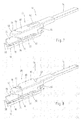
- FIG. 1 a device 10 according to the invention for releasably connecting a wiper blade 12, which is shown in fragmentary form, with a drivable wiper arm 14, which is also shown in fragmentary shown.
- the wiper blade 12 has one of the wiping strip 16, which is to be wiped, not illustrated, and which comprises two strap-like elongated carrying elements 18, 20, a rider element 22 connected to the carrying elements 18, 20 and a connecting element 24 arranged to be swingable on the rider element 22.
- the connecting element 24 serves to connect to a coupling section 26 on the wiper arm 14.
- the coupling portion 26 has, as in particular FIG. 4 becomes clear, a tongue-like insertion section 28 which in the in the FIGS. 1 and 6 shown final assembly position in a receptacle 30 which in FIG. 2 clearly recognizable, intervenes.
- the receptacle 30 is provided in the back 32 of the connecting element 24.
- On the legs 34 of the connecting element 24, a transversely extending bearing receptacle 36 is provided for a bearing pin 38. Due to the bearing seat 36, or the bearing pin 38, a swinging arrangement of the connecting element 24 relative to the rider element 22 is achieved.
- the legs 34 are double-walled.
- the connecting element 24 on its side facing away in the longitudinal direction of the insertion opening 30 on the legs 24 each have a longitudinally extending, elastically yielding in the transverse direction latching tongue 40.
- the latching tongues 40 each comprise a latching edge 42 and an actuating section 44.
- the region of the connecting element 24 which is covered in the final assembly position by the coupling section 26 lies opposite the remaining areas of the connecting element 24, which are essentially of the two actuating sections 24 and one in FIG axial extension of the coupling portion lying head portion 46 are formed, set back. It is thereby achieved that in the final assembly position of the coupling portion 26 and the connecting element 24 form a substantially closed and largely smooth surface.
- the cooperating with the insertion portion 28, adjacent to the insertion opening 30 portion 48 is formed complementary to the insertion section 28.
- the insertion section 28 is, as shown in FIGS FIGS. 4 and 5 becomes clear, formed in the direction of the extension of the wiper arm 14 and in a side view in the direction of the wiper disk arcuate. Accordingly, like that Figures 3 and 5 can be removed, the area 48 also arch-like, or circular segment-like formed.
- the coupling portion is U-shaped in cross-section and a back 50 and adjoining the back leg 52, 54 has.
- the insertion section 28 is arranged free-standing in extension of the back 50.
- locking edges 56 are provided with the longitudinal axis 58 of the Wischarms 14, an angle ⁇ in the range of about 70 ° include (see. FIGS. 5 and 6 ).
- the locking edges 42 of the locking tongues 40 include a corresponding angle ⁇ .
- the insertion section 28 largely linearly along the arrow 64 inserted into the receptacle 30.
- the longitudinal axis of the wiper arm 14 and the longitudinal axis of the connecting element 24 or of the wiper blade 12 form an angle ⁇ which can be in the range of approximately 10 to 100 °.
- the angle ⁇ has a value of about 40 °.
- the coupling section 26 is permanently held in the final assembly position on the connecting element 24.
- the coupling portion 28 abuts a large area at the region 48 of the connecting element 24.
- the end face 68 of the coupling section 26 facing the head region 46 of the connecting element 24 rests against a contact edge 70 of the connecting element that corresponds to it.
- the actuating portions 44 are compressed in facing direction. As a result, the locking edges 42 of the locking tongues 40 come out of the engagement region of the locking edges 56 of the coupling portion 26. Since the operating portions are arranged opposite to each other, the compression of the operating portions 44 by a simple handle, by means of one hand, can be accomplished.
- the coupling portion 26 is then pivoted away from the connecting element 24 until approximately in the FIG. 5 reached pre-assembly position is reached. Subsequently, the Inserted portion 28 led out of the receptacle 30 in the direction opposite to the arrow 64 direction.
- the legs 34 of the connecting element on the side facing the disc have nose-like elevations 72. These serve to support the rider element 22.
- the elevations 22 restrict the pendulum region of the connecting element 24 relative to the rider element 22 conditionally. As a result, an easier assembly and disassembly of the wiper blade 12 from the wiper arm 14 is possible.
- a material recess in the form of a circular cylindrical hole 74 is provided in the bent region of the insertion section 28 in the bent region of the insertion section 28 .
- an encoding can be provided on the connecting element 24 and on the coupling section 26.
- a coding can be realized, for example, by a beveled corner 78 on the leg 54 of the coupling section 26, which is shown in FIG FIG. 4 is shown accordingly.
- the flattened corner 78 may in this case correspond to a complementary material application, not shown in the figures, at the corresponding location of the connecting element 24. Since only one of the two wiper blades, the respective right or respectively left wiper blade, provides a corresponding material application on the connecting element, an unambiguous assignment of the right or left wiper blade to the right or left wiper arm is ensured.
- FIG. 7 illustrated embodiment is generally the same above description of the in the FIGS. 1 to 6 illustrated first embodiment.
- FIG. 7 also the same reference numbers as in FIG. 1 used.
- the essential difference of the embodiment according to FIG. 7 consists in that in the back 50 of the wiper arm 14 belonging to the coupling portion 26 additionally an opening 80 is provided.
- This opening 80 allows air flowing under the U-profile of the coupling section to leave the space formed below the U-profile in a relatively short distance by passing through the opening 80. In this way, the dynamic pressure is reduced below the coupling portion 26 with respect to a design without the opening 80, which leads to the comparative reduction in the lifting force of the wiper arm 14 when it flows.
- a plurality of openings 80 could also be provided in the coupling section 26, wherein one or more openings 80 may also be mounted in one of the two legs 52, 54 or in both legs 52, 54.
- the size, shape and position of the one or more openings 80 should be optimized for maximum effect depending on the geometrical conditions of the individual components of the device 10 and the device 10 as a whole.
- the shape and size of the one or more openings 80 may be adapted to the design of the coupling portion 26.
- FIG. 8 illustrated further embodiment is generally the same above description of the in the FIGS. 1 to 6 illustrated first embodiment.
- the essential difference of the embodiment according to FIG. 8 is that on the back 50 of the coupling portion 26, a spoiler-like air guiding means 82 is formed.
- the back 50 of the coupling section 26 has an approximately rectangular section which extends in the longitudinal direction of the Coupling portion 26 is oriented, cut free at its two narrow sides and on a longitudinal side and bent up out of the plane of the back 50.
- the air guide 82 can be given a rounded, wing-like shape.
- the air guiding means 82 is connected to the back 50 on its longitudinal side facing the incoming air.
- the opening 80 By bending out the opening 80 was formed in the back 50 behind the air guide 82 at the same time, which can be traversed by an air flow.
- the reference line belonging to the reference numeral 80 is shown in dashed lines, because the view of the opening 80 is hidden in this perspective by the air guide 82.
- the air guiding means 82 and the opening 80 can be economically produced by stamping and bending during the manufacturing process of the coupling portion as a punching-bending part made of sheet metal.
- the peculiarity of the embodiment according to FIGS. 9 and 10 is that in the back 50 of the coupling portion 26, an opening is provided and that a arranged on the back 32 of the connecting element 24 spoiler-like air guide 84 extends through this opening through to the top of the coupling portion 26.
- the contact force of the wiper arm 14 is increased or the lifting force is reduced.
- FIG. 9 It can be seen that the shape and size of the opening in the coupling portion 26 and the base of the air guiding means 84 are adapted to each other.
- the air guiding means 84 via a base 86 with the back 32nd connected to the connecting element 24.
- the height of the base 86 corresponds to the wall thickness of the back 50 of the coupling portion 26, so that the top of the back 50 is adjacent to the air guide 84 at least almost gap-free or without offset. This improves aerodynamics and reduces flow noise.
- the opening in the back 50 of the coupling portion 26 may be larger than the base of the air guide 84 and its base 86. In this case, only a portion of the opening would be filled by the air guide 84. The unfilled part of the opening thus acts as a flow opening, which in turn reduces the dynamic pressure under the U-profile of the coupling section 26.
- This embodiment is not shown in the drawing.
- FIGS. 9 and 10 Another embodiment not shown in the drawing is that in a device according to FIGS. 9 and 10 In addition, at least one opening in the back and / or in at least one of the legs 52, 54 is provided to reduce the back pressure under the U-profile of the coupling portion 26.
- FIG. 11 A final embodiment is in FIG. 11 shown. This embodiment corresponds in many features in FIG. 2 shown embodiment, which is why the basic structure is not repeated here again and the same reference numbers are used for the same parts or elements.
- the rider element 22 has two bearing journals 88 which are aligned with one another and project from the rider element 22 transversely to the longitudinal direction of the wiper blade 12.
- the journals 88 of which due to the perspective in figure 11 only one can be seen, are integrally formed with the rider element 22.
- the rider element 22 is advantageous to manufacture a total of metal die-cast or plastic injection molded part.
- the bottleneck of the slot 92 is thereby schaler than the diameter of the respective bearing pin 88.
- the bearing pins 88 in the manner of a snap connection overcoming the bottleneck radially through the slots 92 into the bearing bores 90th pushed in or out of these.
- these processes are significantly simplified, on the other hand, a sufficiently secure fit or stop of the bearing pin 88 is ensured in the bearing bores 90.
- Devices for releasably connecting a wiper blade with a wiper arm according to the embodiments according to the FIGS. 1 to 10 are particularly suitable for use in windshield wipers for vehicles, while the device according to the embodiment according to FIG. 11 especially suitable for use in wiper systems for rear windows of vehicles.
Landscapes
- Engineering & Computer Science (AREA)
- Mechanical Engineering (AREA)
- Pivots And Pivotal Connections (AREA)
- Ink Jet (AREA)
- Transmission Devices (AREA)
- Body Structure For Vehicles (AREA)
- Connection Of Plates (AREA)
Applications Claiming Priority (3)
| Application Number | Priority Date | Filing Date | Title |
|---|---|---|---|
| DE10254978 | 2002-11-26 | ||
| DE10323997A DE10323997A1 (de) | 2002-11-26 | 2003-05-27 | Vorrichtung zum lösbaren Verbinden eines Wischblatts mit einem antreibbaren Wischarm |
| EP03780020A EP1565359B1 (fr) | 2002-11-26 | 2003-11-21 | Dispositif pour raccorder de maniere amovible un balai d'essuie-glace et un bras d'essuie-glace commandable |
Related Parent Applications (2)
| Application Number | Title | Priority Date | Filing Date |
|---|---|---|---|
| EP03780020A Division EP1565359B1 (fr) | 2002-11-26 | 2003-11-21 | Dispositif pour raccorder de maniere amovible un balai d'essuie-glace et un bras d'essuie-glace commandable |
| EP03780020.8 Division | 2003-11-21 |
Related Child Applications (1)
| Application Number | Title | Priority Date | Filing Date |
|---|---|---|---|
| EP10015247.9 Division-Into | 2010-12-03 |
Publications (3)
| Publication Number | Publication Date |
|---|---|
| EP1918166A2 true EP1918166A2 (fr) | 2008-05-07 |
| EP1918166A3 EP1918166A3 (fr) | 2010-05-26 |
| EP1918166B1 EP1918166B1 (fr) | 2011-10-12 |
Family
ID=32240403
Family Applications (1)
| Application Number | Title | Priority Date | Filing Date |
|---|---|---|---|
| EP08101730A Expired - Lifetime EP1918166B1 (fr) | 2002-11-26 | 2003-11-21 | Balai d'essuie-glace déconnectable d'un bras essuie-glace et bras d'essuie-glace |
Country Status (6)
| Country | Link |
|---|---|
| EP (1) | EP1918166B1 (fr) |
| JP (2) | JP5235937B2 (fr) |
| CN (1) | CN100422004C (fr) |
| AT (1) | ATE528180T1 (fr) |
| DE (3) | DE10323997A1 (fr) |
| ES (2) | ES2302960T3 (fr) |
Cited By (2)
| Publication number | Priority date | Publication date | Assignee | Title |
|---|---|---|---|---|
| CN110505986A (zh) * | 2017-03-23 | 2019-11-26 | 日本雨刷片株式会社 | 雨刷片与雨刷臂的结合结构及雨刷片 |
| WO2021170428A1 (fr) | 2020-02-28 | 2021-09-02 | Valeo Systèmes d'Essuyage | Dispositif de connexion d'un balai d'essuyage à un bras d'essuie-glace |
Families Citing this family (17)
| Publication number | Priority date | Publication date | Assignee | Title |
|---|---|---|---|---|
| DE602006020249D1 (de) * | 2006-04-28 | 2011-04-07 | Federal Mogul Sa | Scheibenwischervorrichtung |
| EP2113432B2 (fr) * | 2008-05-02 | 2021-03-24 | Eletromecanica Dyna S/A | Essuie-glace, en particulier pour véhicules automobiles |
| FR2935654B1 (fr) * | 2008-06-09 | 2011-05-27 | Valeo Systemes Dessuyage | Adaptateur de liaison d'un bras d'entrainement d'un balai d'essuie-glace |
| US8286298B2 (en) | 2008-07-11 | 2012-10-16 | Adm21 Co., Ltd. | Device for connecting a flat wiper blade to wiper arms |
| KR100903374B1 (ko) * | 2008-07-11 | 2009-06-23 | 에이디엠이십일 주식회사 | 플랫 와이퍼 블레이드와 와이퍼 아암의 결합장치 |
| DE102008049273A1 (de) * | 2008-09-26 | 2010-04-01 | Valeo Systèmes d'Essuyage | Wischblatt sowie Wischblatt/Wischarmverbindung |
| DE102010030142A1 (de) | 2010-06-16 | 2011-12-22 | Robert Bosch Gmbh | Scheibenwischerverbindungseinheit |
| WO2012026439A1 (fr) * | 2010-08-23 | 2012-03-01 | 株式会社ミツバ | Dispositif essuie-glace |
| AR082500A1 (es) | 2010-09-01 | 2012-12-12 | Ishihara Sangyo Kaisha | Derivado de benzamida o su sal, e insecticida, acaricida, nematicida o pesticida en suelo que lo contiene |
| DE102011077483A1 (de) * | 2011-06-14 | 2012-12-20 | Robert Bosch Gmbh | Wischblatt zum Reinigen von Scheiben insbesondere von Kraftfahrzeugen |
| DE102011057118A1 (de) | 2011-12-29 | 2013-07-04 | Valeo Systèmes d'Essuyage | Wischvorrichtung zum Reinigen von Fahrzeugscheiben |
| DE102014215427A1 (de) * | 2014-08-05 | 2016-02-11 | Robert Bosch Gmbh | Abschließbarer für Finray-Wischer |
| DE102014226365A1 (de) * | 2014-12-18 | 2016-06-23 | Robert Bosch Gmbh | Scheibenwischvorrichtung |
| CN104890638A (zh) * | 2015-05-13 | 2015-09-09 | 丹阳镇威汽配有限公司 | 用于雨刮片和摇臂之间的固定接头机构 |
| CN104925029B (zh) * | 2015-06-15 | 2020-06-23 | 厦门富可汽车配件有限公司 | 雨刷的改进结构 |
| DE102015225984A1 (de) * | 2015-12-18 | 2017-06-22 | Robert Bosch Gmbh | Wischblattvorrichtung |
| CN106240529B (zh) * | 2016-09-23 | 2021-10-22 | 厦门富可汽车配件有限公司 | 一种雨刷连接组件 |
Citations (1)
| Publication number | Priority date | Publication date | Assignee | Title |
|---|---|---|---|---|
| WO2002040328A1 (fr) | 2000-11-18 | 2002-05-23 | Robert Bosch Gmbh | Dispositif de fixation liberable d'un essuie-glace pour le nettoyage de vitres, en particulier de vehicules a moteur, sur un bras d'essuie-glace |
Family Cites Families (14)
| Publication number | Priority date | Publication date | Assignee | Title |
|---|---|---|---|---|
| US2632907A (en) * | 1948-09-21 | 1953-03-31 | Productive Inventions Inc | Connector for wiper blades and arms |
| FR1238655A (fr) * | 1958-10-15 | 1960-08-12 | Rau Swf Autozubehoer | Dispositif de fixation du balai d'essuie-glace de véhicules automobiles |
| US3147508A (en) * | 1963-10-14 | 1964-09-08 | Tridon Mfg Ltd | Attachment clip for automobile windshield wipers |
| US3254358A (en) * | 1963-11-12 | 1966-06-07 | Ralph H Wise | Windshield wiper connector |
| DE3439523C2 (de) * | 1984-10-29 | 1986-10-30 | Daimler-Benz Ag, 7000 Stuttgart | Scheibenwischer für Kraftwagen |
| DE3709915A1 (de) * | 1987-03-26 | 1988-10-13 | Daimler Benz Ag | Scheibenwischer fuer kraftwagen |
| GB8717834D0 (en) * | 1987-07-28 | 1987-09-03 | Trico Folberth Ltd | Connector |
| DE19952054A1 (de) * | 1999-10-28 | 2001-05-03 | Bosch Gmbh Robert | Wischvorrichtung für Scheiben von Kraftfahrzeugen |
| DE10057253A1 (de) * | 2000-11-18 | 2002-05-23 | Bosch Gmbh Robert | Top-Lock-Verbindung Gelenkfreies WBA |
| DE10130903A1 (de) * | 2000-11-18 | 2002-05-23 | Bosch Gmbh Robert | Vorrichtung zum lösbaren Verbinden eines Wischblatts zum Reinigen von Scheiben insbesondere von Kraftfahrzeugen mit einem angetriebenen Wischerarm |
| DE10212441A1 (de) * | 2002-03-21 | 2003-11-13 | Valeo Auto Electric Gmbh | Wischvorrichtung mit Flachwischblatt und Wischarm |
| DE10257990A1 (de) | 2002-04-04 | 2003-10-16 | Bosch Gmbh Robert | Wischhebel mit einem Wischerarm und einem an diesem angelenkten Wischblatt zum Reinigen von Scheiben insbesondere von Kraftfahrzeugen |
| CN100548760C (zh) * | 2002-04-04 | 2009-10-14 | 罗伯特-博希股份公司 | 具有一个刮水臂和一个铰接于该刮水臂上的刮水片的雨刷杆 |
| MXPA05005581A (es) * | 2002-11-26 | 2005-11-23 | Valeo Wischersysteme Gmbh | Dispositivo para la union desmontable de una escobilla con un brazo limpiaparabrisas accionable. |
-
2003
- 2003-05-27 DE DE10323997A patent/DE10323997A1/de not_active Ceased
- 2003-05-27 DE DE10362341.8A patent/DE10362341B3/de not_active Expired - Lifetime
- 2003-11-21 AT AT08101730T patent/ATE528180T1/de active
- 2003-11-21 DE DE20321492U patent/DE20321492U1/de not_active Expired - Lifetime
- 2003-11-21 ES ES03780020T patent/ES2302960T3/es not_active Expired - Lifetime
- 2003-11-21 ES ES08101730T patent/ES2373487T3/es not_active Expired - Lifetime
- 2003-11-21 EP EP08101730A patent/EP1918166B1/fr not_active Expired - Lifetime
- 2003-11-21 CN CNB2003801042162A patent/CN100422004C/zh not_active Expired - Lifetime
-
2010
- 2010-05-10 JP JP2010108482A patent/JP5235937B2/ja not_active Expired - Lifetime
-
2013
- 2013-02-07 JP JP2013022600A patent/JP2013079078A/ja active Pending
Patent Citations (1)
| Publication number | Priority date | Publication date | Assignee | Title |
|---|---|---|---|---|
| WO2002040328A1 (fr) | 2000-11-18 | 2002-05-23 | Robert Bosch Gmbh | Dispositif de fixation liberable d'un essuie-glace pour le nettoyage de vitres, en particulier de vehicules a moteur, sur un bras d'essuie-glace |
Cited By (3)
| Publication number | Priority date | Publication date | Assignee | Title |
|---|---|---|---|---|
| CN110505986A (zh) * | 2017-03-23 | 2019-11-26 | 日本雨刷片株式会社 | 雨刷片与雨刷臂的结合结构及雨刷片 |
| WO2021170428A1 (fr) | 2020-02-28 | 2021-09-02 | Valeo Systèmes d'Essuyage | Dispositif de connexion d'un balai d'essuyage à un bras d'essuie-glace |
| FR3107682A1 (fr) | 2020-02-28 | 2021-09-03 | Valeo Systèmes D’Essuyage | Dispositif de connexion d’un balai d’essuyage à un bras d’essuie-glace |
Also Published As
| Publication number | Publication date |
|---|---|
| ATE528180T1 (de) | 2011-10-15 |
| EP1918166A3 (fr) | 2010-05-26 |
| DE10323997A1 (de) | 2004-06-03 |
| JP2013079078A (ja) | 2013-05-02 |
| DE10362341B3 (de) | 2023-02-09 |
| EP1918166B1 (fr) | 2011-10-12 |
| CN1717350A (zh) | 2006-01-04 |
| ES2302960T3 (es) | 2008-08-01 |
| JP2010195397A (ja) | 2010-09-09 |
| CN100422004C (zh) | 2008-10-01 |
| JP5235937B2 (ja) | 2013-07-10 |
| DE20321492U1 (de) | 2007-10-18 |
| ES2373487T3 (es) | 2012-02-06 |
Similar Documents
| Publication | Publication Date | Title |
|---|---|---|
| EP1565359B1 (fr) | Dispositif pour raccorder de maniere amovible un balai d'essuie-glace et un bras d'essuie-glace commandable | |
| EP1918166B1 (fr) | Balai d'essuie-glace déconnectable d'un bras essuie-glace et bras d'essuie-glace | |
| DE4439109B4 (de) | Mit einer Windleitvorrichtung komplettierbares Wischblatt | |
| EP1071591B1 (fr) | Dispositif pour raccorder de maniere articulee a un bras d'essuie-glace une raclette d'essuie-glace destinee a des vitres de vehicules automobiles | |
| EP1824714B1 (fr) | Bras d'essuie-glace et couvercle pour un bras d'essuie-glace | |
| EP1732792B1 (fr) | Raclette d'essuie-glace | |
| EP1966013B1 (fr) | Element de raccordement | |
| EP2162321B1 (fr) | Balai d'essuie-glace plat | |
| EP1963148B1 (fr) | Dispositif de raccordement pour un bras d'essuie-glace | |
| EP1485280A1 (fr) | Dispositif d'essuie-glace comprenant un balai d'essuie-glace plat et un bras d'essuie-glace | |
| EP2331372B1 (fr) | Raclette d'essuie-glace et assemblage realise entre un bras et une raclette d'un essuie-glace | |
| WO2002051677A1 (fr) | Dispositif d'essuie-glace, en particulier pour vitres de vehicules automobiles | |
| DE10349637B4 (de) | Gelenkverbindung | |
| DE10130903A1 (de) | Vorrichtung zum lösbaren Verbinden eines Wischblatts zum Reinigen von Scheiben insbesondere von Kraftfahrzeugen mit einem angetriebenen Wischerarm | |
| EP0944507A1 (fr) | Essuie-glace | |
| EP2331373B1 (fr) | Dispositif d'assemblage pour la liaison articulée d'un balai d'essuie-glace | |
| DE102019110083A1 (de) | Scheibenwischanlage für einen Kraftwagen | |
| DE10038397B4 (de) | Wischvorrichtung, insbesondere für Kraftfahrzeuge | |
| DE10043427B4 (de) | Wischvorrichtung | |
| EP2179901B1 (fr) | Dispositif de raccordement pour la liaison articulée d'une lame d'essuyage conçue sous la forme d'une barre plate avec un bras d'essuyage | |
| EP1485279A1 (fr) | Dispositif con u pour guider lateralement un balai d'essuie-glace | |
| EP1761421B1 (fr) | Articulation entre un bras d'essuyage et un support de bras d'essuyage et bras d'essuie-glace equipe d'une telle articulation | |
| DE3619589C2 (de) | Wischblatt für Scheibenreinigungsanlagen an Fahrzeugen, insbesondere an Kraftfahrzeugen | |
| DE102005027450B4 (de) | Windabweiser für ein Schiebedach | |
| WO2005002934A1 (fr) | Raccordement entre une raclette d'essuie-glace et un bras de monture d'essuie-glace d'un systeme d'essuie-glace pour vehicules a moteur, et systeme d'essuie-glace muni d'un tel raccordement |
Legal Events
| Date | Code | Title | Description |
|---|---|---|---|
| PUAI | Public reference made under article 153(3) epc to a published international application that has entered the european phase |
Free format text: ORIGINAL CODE: 0009012 |
|
| 17P | Request for examination filed |
Effective date: 20080227 |
|
| AC | Divisional application: reference to earlier application |
Ref document number: 1565359 Country of ref document: EP Kind code of ref document: P |
|
| AK | Designated contracting states |
Kind code of ref document: A2 Designated state(s): AT BE BG CH CY CZ DE DK EE ES FI FR GB GR HU IE IT LI LU MC NL PT RO SE SI SK TR |
|
| PUAL | Search report despatched |
Free format text: ORIGINAL CODE: 0009013 |
|
| AK | Designated contracting states |
Kind code of ref document: A3 Designated state(s): AT BE BG CH CY CZ DE DK EE ES FI FR GB GR HU IE IT LI LU MC NL PT RO SE SI SK TR |
|
| AKX | Designation fees paid |
Designated state(s): AT BE BG CH CY CZ DE DK EE ES FI FR GB GR HU IE IT LI LU MC NL PT RO SE SI SK TR |
|
| RIC1 | Information provided on ipc code assigned before grant |
Ipc: B60S 1/40 20060101ALI20110324BHEP Ipc: B60S 1/38 20060101AFI20110324BHEP |
|
| GRAP | Despatch of communication of intention to grant a patent |
Free format text: ORIGINAL CODE: EPIDOSNIGR1 |
|
| GRAC | Information related to communication of intention to grant a patent modified |
Free format text: ORIGINAL CODE: EPIDOSCIGR1 |
|
| GRAS | Grant fee paid |
Free format text: ORIGINAL CODE: EPIDOSNIGR3 |
|
| GRAA | (expected) grant |
Free format text: ORIGINAL CODE: 0009210 |
|
| AC | Divisional application: reference to earlier application |
Ref document number: 1565359 Country of ref document: EP Kind code of ref document: P |
|
| AK | Designated contracting states |
Kind code of ref document: B1 Designated state(s): AT BE BG CH CY CZ DE DK EE ES FI FR GB GR HU IE IT LI LU MC NL PT RO SE SI SK TR |
|
| REG | Reference to a national code |
Ref country code: GB Ref legal event code: FG4D Free format text: NOT ENGLISH |
|
| REG | Reference to a national code |
Ref country code: CH Ref legal event code: EP |
|
| REG | Reference to a national code |
Ref country code: IE Ref legal event code: FG4D |
|
| REG | Reference to a national code |
Ref country code: NL Ref legal event code: T3 |
|
| REG | Reference to a national code |
Ref country code: DE Ref legal event code: R096 Ref document number: 50314014 Country of ref document: DE Effective date: 20111208 |
|
| REG | Reference to a national code |
Ref country code: RO Ref legal event code: EPE |
|
| REG | Reference to a national code |
Ref country code: ES Ref legal event code: FG2A Ref document number: 2373487 Country of ref document: ES Kind code of ref document: T3 Effective date: 20120206 |
|
| REG | Reference to a national code |
Ref country code: IE Ref legal event code: FD4D |
|
| PG25 | Lapsed in a contracting state [announced via postgrant information from national office to epo] |
Ref country code: SI Free format text: LAPSE BECAUSE OF FAILURE TO SUBMIT A TRANSLATION OF THE DESCRIPTION OR TO PAY THE FEE WITHIN THE PRESCRIBED TIME-LIMIT Effective date: 20111012 Ref country code: SE Free format text: LAPSE BECAUSE OF FAILURE TO SUBMIT A TRANSLATION OF THE DESCRIPTION OR TO PAY THE FEE WITHIN THE PRESCRIBED TIME-LIMIT Effective date: 20111012 Ref country code: GR Free format text: LAPSE BECAUSE OF FAILURE TO SUBMIT A TRANSLATION OF THE DESCRIPTION OR TO PAY THE FEE WITHIN THE PRESCRIBED TIME-LIMIT Effective date: 20120113 Ref country code: PT Free format text: LAPSE BECAUSE OF FAILURE TO SUBMIT A TRANSLATION OF THE DESCRIPTION OR TO PAY THE FEE WITHIN THE PRESCRIBED TIME-LIMIT Effective date: 20120213 |
|
| PG25 | Lapsed in a contracting state [announced via postgrant information from national office to epo] |
Ref country code: MC Free format text: LAPSE BECAUSE OF NON-PAYMENT OF DUE FEES Effective date: 20111130 Ref country code: CY Free format text: LAPSE BECAUSE OF FAILURE TO SUBMIT A TRANSLATION OF THE DESCRIPTION OR TO PAY THE FEE WITHIN THE PRESCRIBED TIME-LIMIT Effective date: 20111012 |
|
| REG | Reference to a national code |
Ref country code: CH Ref legal event code: PL |
|
| REG | Reference to a national code |
Ref country code: HU Ref legal event code: AG4A Ref document number: E013524 Country of ref document: HU |
|
| PG25 | Lapsed in a contracting state [announced via postgrant information from national office to epo] |
Ref country code: EE Free format text: LAPSE BECAUSE OF FAILURE TO SUBMIT A TRANSLATION OF THE DESCRIPTION OR TO PAY THE FEE WITHIN THE PRESCRIBED TIME-LIMIT Effective date: 20111012 Ref country code: IE Free format text: LAPSE BECAUSE OF FAILURE TO SUBMIT A TRANSLATION OF THE DESCRIPTION OR TO PAY THE FEE WITHIN THE PRESCRIBED TIME-LIMIT Effective date: 20111012 Ref country code: BG Free format text: LAPSE BECAUSE OF FAILURE TO SUBMIT A TRANSLATION OF THE DESCRIPTION OR TO PAY THE FEE WITHIN THE PRESCRIBED TIME-LIMIT Effective date: 20120112 Ref country code: SK Free format text: LAPSE BECAUSE OF FAILURE TO SUBMIT A TRANSLATION OF THE DESCRIPTION OR TO PAY THE FEE WITHIN THE PRESCRIBED TIME-LIMIT Effective date: 20111012 Ref country code: LI Free format text: LAPSE BECAUSE OF NON-PAYMENT OF DUE FEES Effective date: 20111130 Ref country code: CH Free format text: LAPSE BECAUSE OF NON-PAYMENT OF DUE FEES Effective date: 20111130 Ref country code: DK Free format text: LAPSE BECAUSE OF FAILURE TO SUBMIT A TRANSLATION OF THE DESCRIPTION OR TO PAY THE FEE WITHIN THE PRESCRIBED TIME-LIMIT Effective date: 20111012 |
|
| PLBE | No opposition filed within time limit |
Free format text: ORIGINAL CODE: 0009261 |
|
| STAA | Information on the status of an ep patent application or granted ep patent |
Free format text: STATUS: NO OPPOSITION FILED WITHIN TIME LIMIT |
|
| 26N | No opposition filed |
Effective date: 20120713 |
|
| REG | Reference to a national code |
Ref country code: DE Ref legal event code: R097 Ref document number: 50314014 Country of ref document: DE Effective date: 20120713 |
|
| REG | Reference to a national code |
Ref country code: AT Ref legal event code: MM01 Ref document number: 528180 Country of ref document: AT Kind code of ref document: T Effective date: 20111121 |
|
| PG25 | Lapsed in a contracting state [announced via postgrant information from national office to epo] |
Ref country code: AT Free format text: LAPSE BECAUSE OF NON-PAYMENT OF DUE FEES Effective date: 20111121 |
|
| PG25 | Lapsed in a contracting state [announced via postgrant information from national office to epo] |
Ref country code: LU Free format text: LAPSE BECAUSE OF NON-PAYMENT OF DUE FEES Effective date: 20111121 |
|
| PG25 | Lapsed in a contracting state [announced via postgrant information from national office to epo] |
Ref country code: FI Free format text: LAPSE BECAUSE OF FAILURE TO SUBMIT A TRANSLATION OF THE DESCRIPTION OR TO PAY THE FEE WITHIN THE PRESCRIBED TIME-LIMIT Effective date: 20111012 |
|
| REG | Reference to a national code |
Ref country code: FR Ref legal event code: PLFP Year of fee payment: 14 |
|
| REG | Reference to a national code |
Ref country code: FR Ref legal event code: PLFP Year of fee payment: 15 |
|
| REG | Reference to a national code |
Ref country code: FR Ref legal event code: CL Name of requester: , FR Effective date: 20170727 |
|
| PGFP | Annual fee paid to national office [announced via postgrant information from national office to epo] |
Ref country code: HU Payment date: 20191024 Year of fee payment: 17 Ref country code: RO Payment date: 20191031 Year of fee payment: 17 Ref country code: NL Payment date: 20191015 Year of fee payment: 17 Ref country code: CZ Payment date: 20191021 Year of fee payment: 17 |
|
| PGFP | Annual fee paid to national office [announced via postgrant information from national office to epo] |
Ref country code: ES Payment date: 20191223 Year of fee payment: 17 Ref country code: BE Payment date: 20191126 Year of fee payment: 17 Ref country code: IT Payment date: 20191121 Year of fee payment: 17 |
|
| PGFP | Annual fee paid to national office [announced via postgrant information from national office to epo] |
Ref country code: GB Payment date: 20191122 Year of fee payment: 17 |
|
| PGFP | Annual fee paid to national office [announced via postgrant information from national office to epo] |
Ref country code: TR Payment date: 20201113 Year of fee payment: 18 |
|
| REG | Reference to a national code |
Ref country code: NL Ref legal event code: MM Effective date: 20201201 |
|
| GBPC | Gb: european patent ceased through non-payment of renewal fee |
Effective date: 20201121 |
|
| PG25 | Lapsed in a contracting state [announced via postgrant information from national office to epo] |
Ref country code: RO Free format text: LAPSE BECAUSE OF NON-PAYMENT OF DUE FEES Effective date: 20201121 Ref country code: CZ Free format text: LAPSE BECAUSE OF NON-PAYMENT OF DUE FEES Effective date: 20201121 |
|
| REG | Reference to a national code |
Ref country code: BE Ref legal event code: MM Effective date: 20201130 |
|
| PG25 | Lapsed in a contracting state [announced via postgrant information from national office to epo] |
Ref country code: HU Free format text: LAPSE BECAUSE OF NON-PAYMENT OF DUE FEES Effective date: 20201122 Ref country code: NL Free format text: LAPSE BECAUSE OF NON-PAYMENT OF DUE FEES Effective date: 20201201 |
|
| PG25 | Lapsed in a contracting state [announced via postgrant information from national office to epo] |
Ref country code: IT Free format text: LAPSE BECAUSE OF NON-PAYMENT OF DUE FEES Effective date: 20201121 |
|
| PG25 | Lapsed in a contracting state [announced via postgrant information from national office to epo] |
Ref country code: GB Free format text: LAPSE BECAUSE OF NON-PAYMENT OF DUE FEES Effective date: 20201121 |
|
| REG | Reference to a national code |
Ref country code: ES Ref legal event code: FD2A Effective date: 20220202 |
|
| PG25 | Lapsed in a contracting state [announced via postgrant information from national office to epo] |
Ref country code: ES Free format text: LAPSE BECAUSE OF NON-PAYMENT OF DUE FEES Effective date: 20201122 |
|
| PG25 | Lapsed in a contracting state [announced via postgrant information from national office to epo] |
Ref country code: BE Free format text: LAPSE BECAUSE OF NON-PAYMENT OF DUE FEES Effective date: 20201130 |
|
| PGFP | Annual fee paid to national office [announced via postgrant information from national office to epo] |
Ref country code: FR Payment date: 20221122 Year of fee payment: 20 Ref country code: DE Payment date: 20221114 Year of fee payment: 20 |
|
| REG | Reference to a national code |
Ref country code: DE Ref legal event code: R071 Ref document number: 50314014 Country of ref document: DE |
|
| PG25 | Lapsed in a contracting state [announced via postgrant information from national office to epo] |
Ref country code: TR Free format text: LAPSE BECAUSE OF NON-PAYMENT OF DUE FEES Effective date: 20211121 |