EP1917445B1 - Druckluftinstallation eines zylinders - Google Patents
Druckluftinstallation eines zylinders Download PDFInfo
- Publication number
- EP1917445B1 EP1917445B1 EP06769459A EP06769459A EP1917445B1 EP 1917445 B1 EP1917445 B1 EP 1917445B1 EP 06769459 A EP06769459 A EP 06769459A EP 06769459 A EP06769459 A EP 06769459A EP 1917445 B1 EP1917445 B1 EP 1917445B1
- Authority
- EP
- European Patent Office
- Prior art keywords
- chamber
- passage
- piston rod
- fluid
- cylinder unit
- Prior art date
- Legal status (The legal status is an assumption and is not a legal conclusion. Google has not performed a legal analysis and makes no representation as to the accuracy of the status listed.)
- Not-in-force
Links
Images


Classifications
-
- F—MECHANICAL ENGINEERING; LIGHTING; HEATING; WEAPONS; BLASTING
- F16—ENGINEERING ELEMENTS AND UNITS; GENERAL MEASURES FOR PRODUCING AND MAINTAINING EFFECTIVE FUNCTIONING OF MACHINES OR INSTALLATIONS; THERMAL INSULATION IN GENERAL
- F16D—COUPLINGS FOR TRANSMITTING ROTATION; CLUTCHES; BRAKES
- F16D25/00—Fluid-actuated clutches
- F16D25/12—Details not specific to one of the before-mentioned types
-
- F—MECHANICAL ENGINEERING; LIGHTING; HEATING; WEAPONS; BLASTING
- F16—ENGINEERING ELEMENTS AND UNITS; GENERAL MEASURES FOR PRODUCING AND MAINTAINING EFFECTIVE FUNCTIONING OF MACHINES OR INSTALLATIONS; THERMAL INSULATION IN GENERAL
- F16B—DEVICES FOR FASTENING OR SECURING CONSTRUCTIONAL ELEMENTS OR MACHINE PARTS TOGETHER, e.g. NAILS, BOLTS, CIRCLIPS, CLAMPS, CLIPS OR WEDGES; JOINTS OR JOINTING
- F16B4/00—Shrinkage connections, e.g. assembled with the parts at different temperature; Force fits; Non-releasable friction-grip fastenings
- F16B4/002—Shrinkage connections, e.g. assembled with the parts at different temperature; Force fits; Non-releasable friction-grip fastenings engaging or disengaging by means of fluid pressure
-
- F—MECHANICAL ENGINEERING; LIGHTING; HEATING; WEAPONS; BLASTING
- F15—FLUID-PRESSURE ACTUATORS; HYDRAULICS OR PNEUMATICS IN GENERAL
- F15B—SYSTEMS ACTING BY MEANS OF FLUIDS IN GENERAL; FLUID-PRESSURE ACTUATORS, e.g. SERVOMOTORS; DETAILS OF FLUID-PRESSURE SYSTEMS, NOT OTHERWISE PROVIDED FOR
- F15B15/00—Fluid-actuated devices for displacing a member from one position to another; Gearing associated therewith
- F15B15/20—Other details, e.g. assembly with regulating devices
-
- F—MECHANICAL ENGINEERING; LIGHTING; HEATING; WEAPONS; BLASTING
- F16—ENGINEERING ELEMENTS AND UNITS; GENERAL MEASURES FOR PRODUCING AND MAINTAINING EFFECTIVE FUNCTIONING OF MACHINES OR INSTALLATIONS; THERMAL INSULATION IN GENERAL
- F16D—COUPLINGS FOR TRANSMITTING ROTATION; CLUTCHES; BRAKES
- F16D25/00—Fluid-actuated clutches
- F16D25/08—Fluid-actuated clutches with fluid-actuated member not rotating with a clutching member
- F16D25/082—Fluid-actuated clutches with fluid-actuated member not rotating with a clutching member the line of action of the fluid-actuated members co-inciding with the axis of rotation
- F16D25/083—Actuators therefor
-
- F—MECHANICAL ENGINEERING; LIGHTING; HEATING; WEAPONS; BLASTING
- F16—ENGINEERING ELEMENTS AND UNITS; GENERAL MEASURES FOR PRODUCING AND MAINTAINING EFFECTIVE FUNCTIONING OF MACHINES OR INSTALLATIONS; THERMAL INSULATION IN GENERAL
- F16D—COUPLINGS FOR TRANSMITTING ROTATION; CLUTCHES; BRAKES
- F16D25/00—Fluid-actuated clutches
- F16D25/08—Fluid-actuated clutches with fluid-actuated member not rotating with a clutching member
- F16D25/088—Fluid-actuated clutches with fluid-actuated member not rotating with a clutching member the line of action of the fluid-actuated members being distinctly separate from the axis of rotation
-
- F—MECHANICAL ENGINEERING; LIGHTING; HEATING; WEAPONS; BLASTING
- F16—ENGINEERING ELEMENTS AND UNITS; GENERAL MEASURES FOR PRODUCING AND MAINTAINING EFFECTIVE FUNCTIONING OF MACHINES OR INSTALLATIONS; THERMAL INSULATION IN GENERAL
- F16D—COUPLINGS FOR TRANSMITTING ROTATION; CLUTCHES; BRAKES
- F16D48/00—External control of clutches
- F16D48/02—Control by fluid pressure
- F16D2048/0212—Details of pistons for primary or secondary cylinders especially adapted for fluid control
-
- F—MECHANICAL ENGINEERING; LIGHTING; HEATING; WEAPONS; BLASTING
- F16—ENGINEERING ELEMENTS AND UNITS; GENERAL MEASURES FOR PRODUCING AND MAINTAINING EFFECTIVE FUNCTIONING OF MACHINES OR INSTALLATIONS; THERMAL INSULATION IN GENERAL
- F16D—COUPLINGS FOR TRANSMITTING ROTATION; CLUTCHES; BRAKES
- F16D2250/00—Manufacturing; Assembly
Definitions
- the invention concerns a system for mounting and/or demounting a cylinder unit in a vehicle, and methods for mounting/demounting a cylinder unit provided in a element which is removably arranged in a vehicle.
- the rod When mounting a cylinder unit with a protruding piston rod in accordance with prior art, the rod is manually retracted into the cylinder unit and locked by inserting a holding device such as for instance a stick or a shaft.
- the holding device keeps the piston rod in place in a retracted position in order to fit the cylinder unit into mounting position.
- the holding device is thereafter removed in order to release the piston rod to an initial position ready to be operated.
- US 5295566 shows a solution demanding a mechanical holding device to be used during installation of a cylinder unit with a protruding piston rod.
- the solution in accordance with prior art includes the use of a specific mechanical tool for installation purposes. Furthermore, when installing the cylinder unit, the assembler must physically operate the retraction of the piston rod. Consequently, the installation procedure in accordance with prior art is quite cumbersome and not very efficient. However, a more significant restriction is the fact that the prior art solution is not applicable for dismounting the cylinder. This known solution is merely suitable when installing the cylinder unit and does not suggest a procedure for demounting the cylinder unit in the case of maintenance or replacement of the cylinder unit.
- GB-A-2 088 010 discloses a system according to the preamble of claim 1 and a method according to the preamble of claim 15.
- This document in particular discloses a system for mounting/demounting a cylinder unit in a vehicle, wherein a piston rod provided with a piston is arranged in the bore of the cylinder unit, which piston and piston rod are displaceably arranged in the axial direction of the bore of the cylinder unit, the bore has an opening provided for an end portion of the piston rod to protrude out from the bore, and the piston separates the cylinder unit into a first chamber and a second chamber, wherein at least a first passage is provided for communication of fluid into or out of the first chamber.
- a lokking ring is initially accommodated in a shallow groove in a support to retain the assembly in a contracted state to facilitate installation.
- the invention in accordance with independent claim 1 comprises a system for mounting and/or demounting a cylinder unit in/from a vehicle.
- a piston rod provided with a piston is arranged in the bore of the cylinder unit.
- the piston and piston rod are arranged to be displaced in the axial direction of the bore of the cylinder unit.
- the bore has an opening provided for an end portion of the piston rod to protrude out from the bore.
- the piston separates the cylinder unit into a first chamber and a second chamber wherein at least a first passage is provided for communication of fluid into or out of the first chamber. In an initial position where the cylinder unit is prepared to be operated, the piston and the piston rod is positioned so that the end portion of the piston rod protrudes out from the mouth of the bore.
- pressurized fluid is introduced into the first chamber preferably through the first passage thereby placing the piston and the piston rod in a mounting/demounting position. In this position the end portion of the piston rod is essentially retracted in the bore.
- the pressurized fluid utilized to bring the piston and the piston rod in a mounting/demounting position may be hydraulic or pneumatic, preferably a pneumatic source will be used for the supply of pressurized fluid.
- Introduction of pressurized fluid into the first chamber causes the pressure in the first chamber to rise, thereby moving the piston and the piston rod away from the mouth of the bore and further into the bore to retract the end portion of the piston rod.
- the first chamber may be provided with some kind of outlet for letting excessive fluid out of the first chamber, when the piston and piston rod are returning to initial position.
- the first passage may function as an outlet and may in one embodiment may be provided with a mouth communicating with the atmosphere. Further the first passage may be provided with an exhaust cap. Alternatively an exhaust chamber may provided for fluid vented out from the first chamber.
- the pressurized fluid may be provided by an existing source present in the vehicle, such as the air source used for the braking system.
- a first valve is provided to control the communication of fluid from the existing source to the first passage.
- the pressurized fluid may be provided by an external source which is arranged for connection to the first passage.
- the system may be provided with a second valve to control the communication of fluid between first passage and atmosphere.
- the second valve may be used when pressurized fluid is provided by an external source.
- the second valve then opens and closes for the fluid entering the first chamber through the first passage. Further, regulating the pressure in the first chamber to place the piston rod in a mounting/dismounting may be carried out by means of the second valve.
- the second valve may be opened after completing the mounting/dismounting of the cylinder unit to vent out the first chamber and to bring piston and piston rod into an initial operating position.
- the second valve may also be provided in a system using an existing source.
- a two way valve may be provided to control the communication of fluid from the first passage to atmosphere and to control the communication of fluid from the existing source to the first passage.
- the cylinder unit to be used in the system according to invention may be a slave cylinder, a clutch actuator, a gear actuator or any other device fitting in a vehicle.
- the current invention also a includes method for mounting/demounting a cylinder unit included in an element which is removably arranged in a vehicle.
- this element is a shift-control unit which is removably arranged in a structure of the vehicle.
- the method comprises the steps of connecting an external source of pressurized fluid to the first passage and letting fluid into the first chamber.
- the first passage may be provided with a nipple for the connection of a tube pipelining between the first passage and the source.
- the inlet of fluid into the passage may be admitted by opening a second valve. After admitting access of fluid into the first chamber the pressure in the first chambers is regulated to place the piston and the piston rod in a position where the end portion of the piston rod is essentially retracted in the bore This regulation may be carried out by the second valve.
- the end portion T is retracted in the bore, the element is ready to be inserted into or removed from the vehicle.
- the second valve may be used to stop fluid from entering the first chamber, before disconnecting the source from the nipple. After removing the pressure source the piston and the piston rod will return to initial operating positions and the excess fluid in the first chamber will be aired out, for instance by opening the second valve.
- the pressure source may be an external pressure source.
- the method comprises the steps of introducing fluid into the first chamber from a source of pressurized fluid provided in the vehicle. The inlet of fluid into the passage may be admitted by opening a first valve. Thereafter the the pressure in the first chamber is regulated to place the piston and the piston rod in a position where the end portion is essentially retracted in the bore.
- This regulation may be carried out by a second valve.
- the element When the end portion of the piston rod is placed in the bore, the element is ready to be inserted into or removed from the structure of the vehicle. Thereafter the pressurized fluid is stopped from entering the first chamber, this might be carried out by closing the first valve.
- the second valve preferably providing communication between atmosphere and the first passage, may be brought to a closed position before introducing fluid into the first chamber.
- the second valve is held in a closed position during mounting/demounting of the element. After mounting/demounting the second valve may be opened to bring the piston rod into an intial operating position.
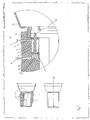
- Fig 1 shows a cylinder unit 1 provided in an element such as a shift-control unit 2.
- the shift-control unit 2 as shown in Fig 1 is inserted into a gear box 3, and is provided for subsequently removal in the case of maintenance etc.
- the cylinder unit 1 comprises a piston 4 having an integrated piston rod 5.
- the piston rod 5 and the piston 4 may provided as separate elements which are connected to each other.
- the piston 4 and the piston rod 5 is arranged to be moved in the axial direction of the bore 6 of the cylinder unit 1.
- the bore 6 has an opening 13 provided for an end portion 14 of the piston rod 5 to protrude out from the bore.
- the end portion 14 might be connected to a transfer rod (not shown) for operation of a clutch. (illustrated by a clutch housing 16).
- the piston 4 divides the bore 6 into a first chamber 7 and a second chamber 8, wherein a spring element 15 is arranged.
- a first passage 9 communicates with the first chamber 7 and a second passage 10 communicates with the second chamber 8.
- First and second passages 9, 10 are provided with first and second nipples 11, 12.
- first chamber 7 and first passage 9 constitute the pneumatic part of the cylinder unit 1
- second chamber 8 and second passage 9 constitute the hydraulic part of the cylinder unit 1.
- the piston 4 and the piston rod 5 is shown placed into an initial operating position, wherein the end portion of the piston rod is to be connected to a transfer rod preparing the system for the operation of the clutch.
- pressurized pneumatic fluid is led through the first passage 9 and into the first chamber 7, by connecting a source of pressurized fluid directly or indirectly to the nipple 11.
- the source of pressurized fluid may be an external source located outside the vehicle.
- the flow of fluid into the first chamber 1 is terminated by disconnecting the external source from the nipple 11. Due to the force of the spring element 15 or hydraulic fluid inserted into the first chamber 7, the piston 4 and piston rod 13 will return to the position as illustrated in fig 2 . The pressurized fluid previously inserted into the first chamber 7, escapes through the first passage 9.
- the first passage 9 may be provided with an exhaust cover.
- a valve-herein called a second valve-(not shown in the figure) may be provided in the first passage 9 to control the communication into and out of the first passage 9.
- the second valve may be used to control the amount of pressurized fluid entering and escaping from the first chamber 7 through the first passage 9.
- the second valve may be used to vent out the first chamber 7 to return the piston 4 and the piston rod 5 to the initial operating position in fig. 1 .
- the system may be arranged with an exhaust chamber (not shown) provided for the pressurized fluid escaping the first chamber 7.
- a second embodiment of the invention is illustrated in fig. 3 .
- a first valve 18 is included in the shift-control unit 2.
- the first valve 18 may be mechanical or electrical or of any kind suitable for this kind of use.
- the pressurized fluid is provided by a source present in the vehicle for instance an air source used in the brake system of the vehicle.
- the first valve 18 controls the flow of pressurized fluid into the passage 9.
- the first valve 18 is opened to introduce pressurized fluid into the passage 9 and the first chamber 7. Thereafter the pressure in the first chamber 7 is regulated by the first valve 18 to retract the piston 4 and the piston rod in the bore 6 into the position as illustrated in fig 3 .
- the shift-control unit 2 After the shift-control unit 2 have been installed or removed the flow of pressurized fluid is stopped using the first valve 18.
- a closure such as a plug 17 is inserted into the passage 9 during the inlet of pressurized fluid from the source.
- the plug 17 may be removed for venting out the first chamber 7, when the installation/removal of the shift-control unit 2 has been completed.
- a second valve may be provided, controlling the communication between the first passage 9 and the atmosphere 19. The second valve may be opened venting out the first chamber 7, thereby bringing the piston 4 and the piston rod 5 into the initial operating position.
- the system may be arranged with an exhaust chamber (not shown) providing for the pressurized fluid escaping from the first chamber 7.
- the first passage 9 may be provided with an exhaust cover.
Landscapes
- Engineering & Computer Science (AREA)
- General Engineering & Computer Science (AREA)
- Mechanical Engineering (AREA)
- Physics & Mathematics (AREA)
- Fluid Mechanics (AREA)
- Actuator (AREA)
Claims (20)
- System zum Montieren, Demontieren einer Zylindereinheit(1) in einem Fahrzeug, wobei eine mit einem Kolben (4) versehene Kolbenstange (5) in der Bohrung (6) der Zylindereinheit angeordnet ist, wobei der Kolben (4) und die Kolbenstange (5) in axialer Richtung der Bohrung (6) der Zylindereinheit verschiebbar angeordnet ist, wobei die Bohrung (6) eine für einen Endbereich der Kolbenstange (5) vorgesehene Öffnung (13) aufweist, damit diese aus der Bohrung (6) heraus vorsteht, und wobei der Koben (4) die Zylindereinheit in eine erste Kammer (7) und eine zweite Kammer (8) unterteilt, wobei wenigstens ein erster Durchgang (9) zum Durchfluss von Fluid in die oder aus der ersten Kammer (7) vorgesehen ist, dadurch gekennzeichnet, dass in einer anfänglichen Arbeitsstellung der Zylindereinheit der Kolben (4) und die Kolbenstange (5) mit dem Endbereich der Kolbenstange (5) aus der Mündung der Bohrung (6) herausragend positioniert ist, dass in einer Montage/Demontage-Stellung der Zylindereinheit unter Druck stehendes Fluid in die erste Kammer (7) eingeführt wird, vorzugsweise durch den ersten Durchgang (9), wodurch der Kolben (4) und die Kolbenstange (5) in eine Montage/Demontage-Stellung gebracht wird, in der der Endbereich der Kolbenstange (5) im Wesentlichen in die Bohrung (6) zurückgezogen ist.
- System nach Anspruch 1, dadurch gekennzeichnet, dass das unter Druck stehende Fluid hydraulisch oder pneumatisch ist.
- System nach Anspruch 1 oder 2, dadurch gekennzeichnet, dass die Zylindereinheit (1) ein Nemazylinder, ein Kupplungsbetätiger oder ein Gangschaltungsbetätiger ist.
- System nach einem der vorhergehenden Ansprüche, dadurch gekennzeichnet, dass die Zylindereinheit (1) in einem Fahrzeugelement vorgesehen ist, vorzugsweise einer abnehmbar in einer Struktur des Fahrzeugs angeordneten Schaltungssteuereinheit.
- System nach einem der vorhergehenden Ansprüche, dadurch gekennzeichnet, dass der erste Durchgang (9) in Verbindung mit der Atmosphäre steht, vorzugsweise durch eine Mündung des ersten Durchgangs (9).
- System nach einem der vorhergehenden Ansprüche, dadurch gekennzeichnet, dass der erste Durchgang (9) mit einer Abgaskappe versehen ist.
- System nach einem der vorhergehenden Ansprüche, dadurch gekennzeichnet, dass eine Abgaskammer für aus der ersten Kammer abzulassendes Fluid vorgesehen ist.
- System nach einem der vorhergehenden Ansprüche, dadurch gekennzeichnet, dass die Mündung des ersten Durchgangs (9) mit einem Stutzen (11) versehen ist.
- System nach einem der vorhergehenden Ansprüche, dadurch gekennzeichnet, dass das unter Druck stehende Fluid durch eine externe, mit dem ersten Durchgang verbundene Quelle bereitgestellt wird.
- System nach einem der vorhergehenden Ansprüche 1 bis 8, dadurch gekennzeichnet, dass das unter Druck stehende Fluid durch eine in dem Fahrzeug vorhandene Quelle bereitgestellt wird, wobei die Quelle zur Verbindung mit dem ersten Durchgang (9) vorgesehen ist.
- System nach Anspruch 9, dadurch gekennzeichnet, dass ein erstes Ventil zur Steuerung des Durchflusses von Fluid aus der vorhandenen Quelle zu dem ersten Durchgang (9) vorgesehen ist.
- System nach einem der vorhergehenden Ansprüche, dadurch gekennzeichnet, dass ein zweites Ventil zum Steuern des Durchflusses von Fluid zwischen dem ersten Durchgang (9) und der Atmosphäre vorgesehen ist.
- System nach Anspruch 10, dadurch gekennzeichnet, dass ein Zweiwegeventil zum Steuern des Durchflusses von Fluid aus dem ersten Durchgang in die Atmosphäre und zum Steuern des Durchflusses von Fluid aus der vorhandenen Quelle zu dem ersten Durchgang vorgesehen ist.
- System nach einem der vorhergehenden Ansprüche 11 bis 13, dadurch gekennzeichnet, dass das erste Ventil mechanisch oder elektrisch betätigt und/oder das zweite Ventil mechanisch oder elektrisch betätigt wird.
- Verfahren zum Montieren/Demontieren einer Zylindereinheit (1), die in einem entnehmbar in einem Fahrzeug angeordneten Element vorgesehen ist, wobei eine Kolbenstange (5) in der Bohrung (6) der Zylindereinheit angeordnet ist und die Kolbenstange (5) mit einem Kolben (4) versehen ist, der verschiebbar in der Bohrung (6) der Zylindereinheit angeordnet ist, wobei die Bohrung (6) eine für einen Endbereich der Kolbenstange (5) vorgesehene Öffnung (13) aufweist, damit diese aus der Bohrung (6) heraus vorstehen kann, und wobei der Kolben (4) die Zylindereinheit in eine erste Kammer (7) und eine zweite Kammer (8) auftrennt, wobei wenigstens ein erster Durchgang (9) zum Durchfluss von Fluid in die oder aus der ersten Kammer (7) vorgesehen ist, dadurch gekennzeichnet, dass das Verfahren die Schritte aufweist:a) Anschließen einer Quelle für unter Druck stehendes Fluid an den ersten Durchgang (9) und Einführen von Fluid in die erste Kammer (7),b) Regeln des Drucks in der ersten Kammer (7), um so den Kolben (4) und die Kolbenstange (5) in eine Stellung zu positionieren, in der der Endbereich der Kolbenstange (5) im Wesentlichen in die Bohrung (6) zurückgezogen ist,c) Einsetzen/Entfernen des Elements in das/aus dem Fahrzeug,d) Abtrennen der Druckquelle.
- Verfahren nach Anspruch 15, dadurch gekennzeichnet, dass die verwendete Druckquelle eine externe Quelle für unter Druck stehendes Fluid ist.
- Verfahren zum Montieren/Demontieren gemäß Anspruch 16, gekennzeichnet durcha) Öffnen eines zweiten Ventils zur Einfuhr von Fluid in die erste Kammer,b) optionales Verwenden des zweiten Ventils zum Regeln des Druckes in der ersten Kammer,c) Schließen des zweiten Ventils, um den Eintritt von Fluid in die erste Kammer zu stoppen.
- Verfahren nach Anspruch 15, dadurch gekennzeichnet, dass die verwendete Druckquelle eine in dem Fahrzeug vorgesehene Quelle für unter Druck stehendes Fluid ist.
- Verfahren zum Montieren/Demontieren gemäß Anspruch 18, gekennzeichnet durcha) Öffnen eines ersten Ventils zum Einführen von Fluid in die erste Kammer,b) optionales Verwenden eines zweiten Ventils zum Regeln des Druckes in der ersten Kammer,c) Schließen des ersten Ventils, um den Eintritt des Fluids in die erste Kammer zu stoppen.
- Verfahren zum Montieren/Demontieren gemäß Anspruch 18 oder 19, dadurch gekennzeichnet, dass vor a) ein zweites Ventil geschlossen wird, um den Durchfluss zwischen Atmosphäre und dem ersten Durchgang zu blockieren, wobei das Verfahren weiterhin den Schritt aufweist:e) Öffnen des zweiten Ventils, um den Kolben in eine anfängliche Betriebsstellung zu bringen.
Applications Claiming Priority (2)
| Application Number | Priority Date | Filing Date | Title |
|---|---|---|---|
| SE0501882A SE529252C2 (sv) | 2005-08-24 | 2005-08-24 | System och metod för montering/demontering av en cylinderenhet i ett fordon |
| PCT/NO2006/000292 WO2007024137A1 (en) | 2005-08-24 | 2006-08-07 | Pneumatic installation of cylinder (pic) |
Publications (2)
| Publication Number | Publication Date |
|---|---|
| EP1917445A1 EP1917445A1 (de) | 2008-05-07 |
| EP1917445B1 true EP1917445B1 (de) | 2009-06-03 |
Family
ID=37131326
Family Applications (1)
| Application Number | Title | Priority Date | Filing Date |
|---|---|---|---|
| EP06769459A Not-in-force EP1917445B1 (de) | 2005-08-24 | 2006-08-07 | Druckluftinstallation eines zylinders |
Country Status (7)
| Country | Link |
|---|---|
| US (1) | US20080190283A1 (de) |
| EP (1) | EP1917445B1 (de) |
| CN (1) | CN101287914B (de) |
| AT (1) | ATE433056T1 (de) |
| DE (1) | DE602006007152D1 (de) |
| SE (1) | SE529252C2 (de) |
| WO (1) | WO2007024137A1 (de) |
Families Citing this family (3)
| Publication number | Priority date | Publication date | Assignee | Title |
|---|---|---|---|---|
| JP4358222B2 (ja) * | 2006-11-30 | 2009-11-04 | 本田技研工業株式会社 | クラッチアクチュエータを備えるエンジン |
| SE530938C2 (sv) | 2007-02-22 | 2008-10-28 | Kongsberg Automotive As | Manövreringsorgan för koppling |
| CN110173478B (zh) * | 2019-06-05 | 2020-05-05 | 浙江厚达智能科技股份有限公司 | 中药生产用驱动机构 |
Family Cites Families (7)
| Publication number | Priority date | Publication date | Assignee | Title |
|---|---|---|---|---|
| US4282800A (en) * | 1978-10-16 | 1981-08-11 | Automotive Products Limited | Fluid pressure actuator |
| DE2915989C2 (de) * | 1979-04-20 | 1987-02-12 | Fichtel & Sachs Ag, 8720 Schweinfurt | Verriegelungseinrichtung für ein Ausrücksystem |
| DE3044048A1 (de) * | 1980-11-22 | 1982-07-15 | Fichtel & Sachs Ag, 8720 Schweinfurt | Hydraulische betaetigung fuer ein gezogene kupplung |
| EP0273701A3 (de) * | 1987-01-03 | 1989-12-27 | LUCAS INDUSTRIES public limited company | Hydraulikkolben und- zylindereinheiten |
| JPH03194201A (ja) * | 1989-12-22 | 1991-08-23 | Daikin Mfg Co Ltd | 3ポジションアクチュエータ |
| DE4304964C2 (de) * | 1992-02-28 | 2001-11-22 | Valeo | Kupplungsausrücklager, insbesondere für Kraftfahrzeuge |
| CN2471466Y (zh) * | 2001-03-02 | 2002-01-16 | 王智 | 铰制孔用螺栓液压拆卸装置 |
-
2005
- 2005-08-24 SE SE0501882A patent/SE529252C2/sv not_active IP Right Cessation
-
2006
- 2006-08-07 WO PCT/NO2006/000292 patent/WO2007024137A1/en not_active Ceased
- 2006-08-07 CN CN2006800304890A patent/CN101287914B/zh not_active Expired - Fee Related
- 2006-08-07 DE DE602006007152T patent/DE602006007152D1/de active Active
- 2006-08-07 US US12/064,459 patent/US20080190283A1/en not_active Abandoned
- 2006-08-07 AT AT06769459T patent/ATE433056T1/de not_active IP Right Cessation
- 2006-08-07 EP EP06769459A patent/EP1917445B1/de not_active Not-in-force
Also Published As
| Publication number | Publication date |
|---|---|
| CN101287914A (zh) | 2008-10-15 |
| ATE433056T1 (de) | 2009-06-15 |
| US20080190283A1 (en) | 2008-08-14 |
| DE602006007152D1 (de) | 2009-07-16 |
| CN101287914B (zh) | 2011-07-06 |
| EP1917445A1 (de) | 2008-05-07 |
| SE529252C2 (sv) | 2007-06-12 |
| WO2007024137A1 (en) | 2007-03-01 |
| SE0501882L (sv) | 2007-02-25 |
Similar Documents
| Publication | Publication Date | Title |
|---|---|---|
| US4503678A (en) | Reservoirs for liquid pressure control systems and a method of filling the same | |
| US4687084A (en) | Clutch release apparatus for pull type clutches | |
| EP2760719B1 (de) | Internes beatmungssystem mit feststellbremskammer | |
| US10386870B2 (en) | Thermostatic device for controlling the flow of a fluid, and thermostatic valve comprising such a device | |
| EP2792558B1 (de) | Federbremsenaktuator | |
| KR102369739B1 (ko) | 밸브 장치 | |
| WO2016006817A1 (ko) | 브레이크 액추에이터 | |
| EP1917445B1 (de) | Druckluftinstallation eines zylinders | |
| KR20110125284A (ko) | 안티록 브레이크시스템용 저압어큐뮬레이터 | |
| US20180292117A1 (en) | High flow filling equipment and method | |
| EP3168100B1 (de) | Bremsaktuator mit dichtungsanordnung für interne luftzirkulation | |
| US10591009B2 (en) | Vehicle spring brakes having reduced length | |
| CN109305156A (zh) | 具有内呼吸结构的epb阀总成及epb电子驻车制动系统 | |
| FI118233B (fi) | Radiaalimäntähydraulimoottori ja menetelmä radiaalimäntähydraulimoottorin säädössä | |
| US4979366A (en) | Method of providing modular prefilled hydraulic control apparatus | |
| EP0955221B1 (de) | Schnellkupplung für ein hydraulisches Steuersystem | |
| EP1524163A2 (de) | Modulator | |
| WO1995025028A2 (en) | Hydraulic actuating systems | |
| US6405755B1 (en) | Directly controlled magnetic valve | |
| US4756159A (en) | Prefilling apparatus for modular prefilled hydraulic control apparatus | |
| US6540058B2 (en) | Actuation device for a friction clutch in a drivetrain | |
| CN207389184U (zh) | 集成式继动阀带abs电磁阀总成 | |
| US20070107784A1 (en) | Pressure control valve | |
| EP3840993B1 (de) | Komponenten eines druckluftbremssteuermoduls | |
| US20040207251A1 (en) | Integrated disk brake assembly |
Legal Events
| Date | Code | Title | Description |
|---|---|---|---|
| PUAI | Public reference made under article 153(3) epc to a published international application that has entered the european phase |
Free format text: ORIGINAL CODE: 0009012 |
|
| 17P | Request for examination filed |
Effective date: 20080204 |
|
| AK | Designated contracting states |
Kind code of ref document: A1 Designated state(s): AT BE BG CH CY CZ DE DK EE ES FI FR GB GR HU IE IS IT LI LT LU LV MC NL PL PT RO SE SI SK TR |
|
| 17Q | First examination report despatched |
Effective date: 20080722 |
|
| GRAP | Despatch of communication of intention to grant a patent |
Free format text: ORIGINAL CODE: EPIDOSNIGR1 |
|
| GRAS | Grant fee paid |
Free format text: ORIGINAL CODE: EPIDOSNIGR3 |
|
| GRAA | (expected) grant |
Free format text: ORIGINAL CODE: 0009210 |
|
| AK | Designated contracting states |
Kind code of ref document: B1 Designated state(s): AT BE BG CH CY CZ DE DK EE ES FI FR GB GR HU IE IS IT LI LT LU LV MC NL PL PT RO SE SI SK TR |
|
| REG | Reference to a national code |
Ref country code: GB Ref legal event code: FG4D |
|
| REG | Reference to a national code |
Ref country code: CH Ref legal event code: EP |
|
| REG | Reference to a national code |
Ref country code: IE Ref legal event code: FG4D |
|
| REF | Corresponds to: |
Ref document number: 602006007152 Country of ref document: DE Date of ref document: 20090716 Kind code of ref document: P |
|
| REG | Reference to a national code |
Ref country code: DE Ref legal event code: R096 Ref document number: 602006007152 Country of ref document: DE Effective date: 20090716 |
|
| PG25 | Lapsed in a contracting state [announced via postgrant information from national office to epo] |
Ref country code: FI Free format text: LAPSE BECAUSE OF FAILURE TO SUBMIT A TRANSLATION OF THE DESCRIPTION OR TO PAY THE FEE WITHIN THE PRESCRIBED TIME-LIMIT Effective date: 20090603 Ref country code: LT Free format text: LAPSE BECAUSE OF FAILURE TO SUBMIT A TRANSLATION OF THE DESCRIPTION OR TO PAY THE FEE WITHIN THE PRESCRIBED TIME-LIMIT Effective date: 20090603 Ref country code: AT Free format text: LAPSE BECAUSE OF FAILURE TO SUBMIT A TRANSLATION OF THE DESCRIPTION OR TO PAY THE FEE WITHIN THE PRESCRIBED TIME-LIMIT Effective date: 20090603 |
|
| NLV1 | Nl: lapsed or annulled due to failure to fulfill the requirements of art. 29p and 29m of the patents act | ||
| PG25 | Lapsed in a contracting state [announced via postgrant information from national office to epo] |
Ref country code: NL Free format text: LAPSE BECAUSE OF FAILURE TO SUBMIT A TRANSLATION OF THE DESCRIPTION OR TO PAY THE FEE WITHIN THE PRESCRIBED TIME-LIMIT Effective date: 20090603 Ref country code: PL Free format text: LAPSE BECAUSE OF FAILURE TO SUBMIT A TRANSLATION OF THE DESCRIPTION OR TO PAY THE FEE WITHIN THE PRESCRIBED TIME-LIMIT Effective date: 20090603 Ref country code: LV Free format text: LAPSE BECAUSE OF FAILURE TO SUBMIT A TRANSLATION OF THE DESCRIPTION OR TO PAY THE FEE WITHIN THE PRESCRIBED TIME-LIMIT Effective date: 20090603 Ref country code: SE Free format text: LAPSE BECAUSE OF FAILURE TO SUBMIT A TRANSLATION OF THE DESCRIPTION OR TO PAY THE FEE WITHIN THE PRESCRIBED TIME-LIMIT Effective date: 20090903 Ref country code: SI Free format text: LAPSE BECAUSE OF FAILURE TO SUBMIT A TRANSLATION OF THE DESCRIPTION OR TO PAY THE FEE WITHIN THE PRESCRIBED TIME-LIMIT Effective date: 20090603 |
|
| PG25 | Lapsed in a contracting state [announced via postgrant information from national office to epo] |
Ref country code: ES Free format text: LAPSE BECAUSE OF FAILURE TO SUBMIT A TRANSLATION OF THE DESCRIPTION OR TO PAY THE FEE WITHIN THE PRESCRIBED TIME-LIMIT Effective date: 20090914 Ref country code: IS Free format text: LAPSE BECAUSE OF FAILURE TO SUBMIT A TRANSLATION OF THE DESCRIPTION OR TO PAY THE FEE WITHIN THE PRESCRIBED TIME-LIMIT Effective date: 20091003 Ref country code: RO Free format text: LAPSE BECAUSE OF FAILURE TO SUBMIT A TRANSLATION OF THE DESCRIPTION OR TO PAY THE FEE WITHIN THE PRESCRIBED TIME-LIMIT Effective date: 20090603 Ref country code: EE Free format text: LAPSE BECAUSE OF FAILURE TO SUBMIT A TRANSLATION OF THE DESCRIPTION OR TO PAY THE FEE WITHIN THE PRESCRIBED TIME-LIMIT Effective date: 20090603 Ref country code: CZ Free format text: LAPSE BECAUSE OF FAILURE TO SUBMIT A TRANSLATION OF THE DESCRIPTION OR TO PAY THE FEE WITHIN THE PRESCRIBED TIME-LIMIT Effective date: 20090603 |
|
| PG25 | Lapsed in a contracting state [announced via postgrant information from national office to epo] |
Ref country code: SK Free format text: LAPSE BECAUSE OF FAILURE TO SUBMIT A TRANSLATION OF THE DESCRIPTION OR TO PAY THE FEE WITHIN THE PRESCRIBED TIME-LIMIT Effective date: 20090603 Ref country code: BE Free format text: LAPSE BECAUSE OF FAILURE TO SUBMIT A TRANSLATION OF THE DESCRIPTION OR TO PAY THE FEE WITHIN THE PRESCRIBED TIME-LIMIT Effective date: 20090603 |
|
| PG25 | Lapsed in a contracting state [announced via postgrant information from national office to epo] |
Ref country code: BG Free format text: LAPSE BECAUSE OF FAILURE TO SUBMIT A TRANSLATION OF THE DESCRIPTION OR TO PAY THE FEE WITHIN THE PRESCRIBED TIME-LIMIT Effective date: 20090903 Ref country code: PT Free format text: LAPSE BECAUSE OF FAILURE TO SUBMIT A TRANSLATION OF THE DESCRIPTION OR TO PAY THE FEE WITHIN THE PRESCRIBED TIME-LIMIT Effective date: 20091003 Ref country code: MC Free format text: LAPSE BECAUSE OF NON-PAYMENT OF DUE FEES Effective date: 20090831 |
|
| PLBE | No opposition filed within time limit |
Free format text: ORIGINAL CODE: 0009261 |
|
| STAA | Information on the status of an ep patent application or granted ep patent |
Free format text: STATUS: NO OPPOSITION FILED WITHIN TIME LIMIT |
|
| PG25 | Lapsed in a contracting state [announced via postgrant information from national office to epo] |
Ref country code: DK Free format text: LAPSE BECAUSE OF FAILURE TO SUBMIT A TRANSLATION OF THE DESCRIPTION OR TO PAY THE FEE WITHIN THE PRESCRIBED TIME-LIMIT Effective date: 20090603 |
|
| 26N | No opposition filed |
Effective date: 20100304 |
|
| REG | Reference to a national code |
Ref country code: FR Ref legal event code: ST Effective date: 20100430 |
|
| REG | Reference to a national code |
Ref country code: IE Ref legal event code: MM4A |
|
| REG | Reference to a national code |
Ref country code: DE Ref legal event code: R097 Ref document number: 602006007152 Country of ref document: DE Effective date: 20100303 |
|
| PG25 | Lapsed in a contracting state [announced via postgrant information from national office to epo] |
Ref country code: FR Free format text: LAPSE BECAUSE OF NON-PAYMENT OF DUE FEES Effective date: 20090831 Ref country code: IE Free format text: LAPSE BECAUSE OF NON-PAYMENT OF DUE FEES Effective date: 20090807 |
|
| PG25 | Lapsed in a contracting state [announced via postgrant information from national office to epo] |
Ref country code: GR Free format text: LAPSE BECAUSE OF FAILURE TO SUBMIT A TRANSLATION OF THE DESCRIPTION OR TO PAY THE FEE WITHIN THE PRESCRIBED TIME-LIMIT Effective date: 20090904 |
|
| PG25 | Lapsed in a contracting state [announced via postgrant information from national office to epo] |
Ref country code: IT Free format text: LAPSE BECAUSE OF FAILURE TO SUBMIT A TRANSLATION OF THE DESCRIPTION OR TO PAY THE FEE WITHIN THE PRESCRIBED TIME-LIMIT Effective date: 20090603 |
|
| REG | Reference to a national code |
Ref country code: CH Ref legal event code: PL |
|
| GBPC | Gb: european patent ceased through non-payment of renewal fee |
Effective date: 20100807 |
|
| PG25 | Lapsed in a contracting state [announced via postgrant information from national office to epo] |
Ref country code: LU Free format text: LAPSE BECAUSE OF NON-PAYMENT OF DUE FEES Effective date: 20090807 Ref country code: CH Free format text: LAPSE BECAUSE OF NON-PAYMENT OF DUE FEES Effective date: 20100831 Ref country code: LI Free format text: LAPSE BECAUSE OF NON-PAYMENT OF DUE FEES Effective date: 20100831 |
|
| PG25 | Lapsed in a contracting state [announced via postgrant information from national office to epo] |
Ref country code: HU Free format text: LAPSE BECAUSE OF FAILURE TO SUBMIT A TRANSLATION OF THE DESCRIPTION OR TO PAY THE FEE WITHIN THE PRESCRIBED TIME-LIMIT Effective date: 20091204 |
|
| PG25 | Lapsed in a contracting state [announced via postgrant information from national office to epo] |
Ref country code: GB Free format text: LAPSE BECAUSE OF NON-PAYMENT OF DUE FEES Effective date: 20100807 Ref country code: TR Free format text: LAPSE BECAUSE OF FAILURE TO SUBMIT A TRANSLATION OF THE DESCRIPTION OR TO PAY THE FEE WITHIN THE PRESCRIBED TIME-LIMIT Effective date: 20090603 |
|
| PG25 | Lapsed in a contracting state [announced via postgrant information from national office to epo] |
Ref country code: CY Free format text: LAPSE BECAUSE OF FAILURE TO SUBMIT A TRANSLATION OF THE DESCRIPTION OR TO PAY THE FEE WITHIN THE PRESCRIBED TIME-LIMIT Effective date: 20090603 |
|
| PGFP | Annual fee paid to national office [announced via postgrant information from national office to epo] |
Ref country code: DE Payment date: 20230705 Year of fee payment: 18 |
|
| REG | Reference to a national code |
Ref country code: DE Ref legal event code: R119 Ref document number: 602006007152 Country of ref document: DE |
|
| PG25 | Lapsed in a contracting state [announced via postgrant information from national office to epo] |
Ref country code: DE Free format text: LAPSE BECAUSE OF NON-PAYMENT OF DUE FEES Effective date: 20250301 |