EP1917413B1 - Verschluss zur mehrpunktverriegelung von türen oder wandteilen in gehäusen oder schränken - Google Patents
Verschluss zur mehrpunktverriegelung von türen oder wandteilen in gehäusen oder schränken Download PDFInfo
- Publication number
- EP1917413B1 EP1917413B1 EP20060776817 EP06776817A EP1917413B1 EP 1917413 B1 EP1917413 B1 EP 1917413B1 EP 20060776817 EP20060776817 EP 20060776817 EP 06776817 A EP06776817 A EP 06776817A EP 1917413 B1 EP1917413 B1 EP 1917413B1
- Authority
- EP
- European Patent Office
- Prior art keywords
- lever
- lock according
- lock
- double
- door
- Prior art date
- Legal status (The legal status is an assumption and is not a legal conclusion. Google has not performed a legal analysis and makes no representation as to the accuracy of the status listed.)
- Expired - Lifetime
Links
Images





Classifications
-
- E—FIXED CONSTRUCTIONS
- E05—LOCKS; KEYS; WINDOW OR DOOR FITTINGS; SAFES
- E05C—BOLTS OR FASTENING DEVICES FOR WINGS, SPECIALLY FOR DOORS OR WINDOWS
- E05C9/00—Arrangements of simultaneously actuated bolts or other securing devices at well-separated positions on the same wing
- E05C9/10—Actuating mechanisms for bars
- E05C9/16—Actuating mechanisms for bars with crank pins and connecting rods
-
- E—FIXED CONSTRUCTIONS
- E05—LOCKS; KEYS; WINDOW OR DOOR FITTINGS; SAFES
- E05C—BOLTS OR FASTENING DEVICES FOR WINGS, SPECIALLY FOR DOORS OR WINDOWS
- E05C9/00—Arrangements of simultaneously actuated bolts or other securing devices at well-separated positions on the same wing
- E05C9/18—Details of fastening means or of fixed retaining means for the ends of bars
- E05C9/1825—Fastening means
- E05C9/1875—Fastening means performing pivoting movements
-
- E—FIXED CONSTRUCTIONS
- E05—LOCKS; KEYS; WINDOW OR DOOR FITTINGS; SAFES
- E05C—BOLTS OR FASTENING DEVICES FOR WINGS, SPECIALLY FOR DOORS OR WINDOWS
- E05C9/00—Arrangements of simultaneously actuated bolts or other securing devices at well-separated positions on the same wing
- E05C9/24—Means for transmitting movements between vertical and horizontal sliding bars, rods or cables for the fastening of wings, e.g. corner guides
-
- Y—GENERAL TAGGING OF NEW TECHNOLOGICAL DEVELOPMENTS; GENERAL TAGGING OF CROSS-SECTIONAL TECHNOLOGIES SPANNING OVER SEVERAL SECTIONS OF THE IPC; TECHNICAL SUBJECTS COVERED BY FORMER USPC CROSS-REFERENCE ART COLLECTIONS [XRACs] AND DIGESTS
- Y10—TECHNICAL SUBJECTS COVERED BY FORMER USPC
- Y10T—TECHNICAL SUBJECTS COVERED BY FORMER US CLASSIFICATION
- Y10T292/00—Closure fasteners
- Y10T292/08—Bolts
- Y10T292/1043—Swinging
- Y10T292/1044—Multiple head
- Y10T292/1045—Operating means
- Y10T292/1047—Closure
Definitions
- the invention relates to a closure for multi-point locking of doors or wall parts in housings or cabinets, by means of a - optionally securable in a Verschoudregna - actuating element, such as handle lever comprising a rotatably connected to the mounted in the door or wall actuator, a rotational movement in a substantially translational movement converting coupling element which is coupled to a displaceably mounted near the edge of the door or wall rod with which in turn one or more locking elements are each coupled by means of a coupling element such that they by displacement of the rod from a first position to a second position from a locked position to an unlocked position (or vice versa) pass, wherein the locking elements and the coupling elements are each formed by a two-armed one-piece lever, one lever arm is a locking tongue, and its and lever arm is hinged with its end to the rod.
- the inventors also a closure is known in which a rod by means of one-armed lever means on the edge of a door is substantially parallel to the door edge displaceable.
- On the area of the pivot bearing of the one-armed lever can be similar to the WO-writing Vorreiberzonne in four different positions, which are provided at a distance of 90 degrees angle, attach.
- a lever carries no Vorreiberzunge, but is connected to a drive shaft of a Schwenkhebeleldrehantriebs.
- a closure for multipoint locking a cabinet door in which a pinion drives two counter-rotating rods at the ends of a lever arm of a closing lever is hinged, which is provided with a runner which engages behind a rear surface formed by the door frame when the rods are moved in the closing direction ,
- the integrally designed double lever on the one hand, the function of the locking tongue, on the other hand, the function of coupling and motion conversion translation in rotation between the locking tongue and rod.
- the one lever arm is a locking tongue, while the other lever arm is hinged with its end to the rod and thereby forms a driver. Upon actuation of the closure, therefore, the locking tongue is driven directly from the rod.
- the object of the invention is a further simplification and cheapening of the known constructions and the creation of a simple and inexpensive drive for multipoint locks with locking tongues.
- the object is achieved according to the invention in that at least one of the plurality of two-armed lever in rotationally rigid connection with the drive shaft of an operating element, and that its two lever arms form an angle of 120 to 150, preferably approximately 135 (or 225) degrees.
- This results in a central drive of several movable locking elements via a push rod, wherein also the push rod adjusting the drive bolt of a such locking elements is formed, resulting in a particularly simple closure structure.
- the two-armed lever is rotatably mounted at the intersection of the axes of the two lever arms on the door or the wall or on a held by this carrier, such as stiffening profile.
- the respective last double lever of a rod on another Anlenkungsdorfkeit for a further driving rod which is displaceable in the same or different direction, in particular perpendicular to the double lever driving rod. This allows multiple edges to lock on the door.
- a double lever is also hinged to these other rods (claim 4).
- the double lever may (claim 5) comprise a third lever, which is arranged offset to the other lever by 180 degrees and drives a further rod.
- the articulation can (claim 6) by a pin-hole system or by a screw connection, or by a riveted joint.
- the storage of the double lever can be done (claim 7) by means of a heel and ring shoulder ending sleeve, the diameter and height of the heel are selected so that the double lever is rotatably supported with little play on the heel.
- the sleeve may (claim 8) a threaded hole for receiving one of the Have attachment surface outgoing threaded bolt on the one hand and a cap screw on the other.
- the threaded sleeve can (claim 9) expediently have at least partially prismatic cross-section, as flattened laterally or be executed as a hexagon.
- the sleeve can be easily on an existing stud or the like. Screwed.
- the sleeve is a through sleeve, through which a head screw is guided, which is screwed into a nut, such as press-fit, weld-on or normal nut, or in a threaded passage in a double wall or an angle or frame (claim 11).
- the sleeve may be a passage sleeve through which a threaded bolt is guided, which is pressed on the mounting surface, welded or possibly bolted with a gasket, the double lever by a nut screwed onto the bolt, such as stop nut, if necessary Interposed layer of a washer is held (claim 13).
- the double lever may have in its storage area a rinsedNorsprung for positive reception of a driver or square, which in turn is part of a shutter drive or driven by the mandrel or its shaft (claim 14).
- the closure drive may comprise a locking lever which can be folded into a trough and which can optionally be locked in the folded-in position (claim 15).
- the one lever arm 30 is a locking tongue, with a Auftaufschräge 38.
- the other lever arm 32 is articulated at its end 34 to the rod 24.
- At least one of the two-armed levers 22, 122, 222 is linked in rotationally rigid connection with the drive shaft 42 of an actuating element 16.
- the respective last double lever 122 of a rod 24 may have a Anlenkungswagkeit for another driver rod 124, in the same or different Direction 124 and 224, in particular perpendicular to the double lever 222 driving rod 224 is displaceable, see the arrows 20, 120, 220.
- double lever 322 may also be hinged.
- the double lever 222 may have a third lever arm 46, the axis 48 to the axis 50 of the other articulated lever 132 to z. B. offset 90 or 120 degrees relative to the ashes 50 and another rod 124 drives.
- the articulation between a rod 24 on the one hand and the double-armed lever 122 on the other hand can be done by a pin-hole system, see the reference numeral 54, 56, see Fig. 6A , Alternatively, the articulation can be done by screwing or by riveting, which opens up corresponding rotation possibilities.
- the storage of the double lever 122 takes place, for example, by means of a sleeve 58 terminating in step 58 and annular shoulder 60, wherein the diameter and height of the shoulder 58 are chosen so that the double lever 122 is held rotatably on the shoulder 58 with little play.
- the sleeve 262 has a threaded bore 64 for receiving a threaded bolt 66 extending from the mounting surface 212 on the one hand and a cap screw 68 on the other hand.
- the threaded bolt 66 may be pressed into a sheet metal door leaf 212, welded or, preferably using a seal, be screwed into the door leaf, in which last case the door leaf 212 may be made of any material, eg. B. plastic.
- the screwing of the threaded sleeve 262 is facilitated when this threaded sleeve 262 has at least partially prismatic cross-section, z. B. is laterally flattened or designed as a hexagon.
- sleeve 162 may also be a through-tube through which is threaded a cap screw 168 which screws into a nut 70, such as a press fit, weld nut or normal nut, or into a threaded passage in a double wall 44, or an angle or frame is.
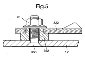
- FIG. 5 represents where a sleeve 362 is designed as a passage sleeve through which a threaded bolt 366 is guided, which is pressed onto the mounting surface 12, welded or, if necessary, with gasket, screwed, the double lever or the locking tab 322 by a on the bolt 366 nut screwed on, such as stop nut 72, possibly with the interposition of a washer, see reference number 74 in Fig. 6B , is held.
- a sleeve 362 is designed as a passage sleeve through which a threaded bolt 366 is guided, which is pressed onto the mounting surface 12, welded or, if necessary, with gasket, screwed, the double lever or the locking tab 322 by a on the bolt 366 nut screwed on, such as stop nut 72, possibly with the interposition of a washer, see reference number 74 in Fig. 6B , is held.
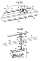
- Fig. 7A is a closure to recognize, in which the double lever 222 has in its storage area a remindsprungNorsprung 78 for positive reception of a driver 176 or a square, which in turn is part of a shutter drive 80 or driven by the mandrel or shaft 82.
- the closure drive 80 comprises a locking lever 86 which can be folded into a trough 84 and which is articulated at the end of the shaft 82 and optionally in the folded-in position, as in FIG Fig. 7B recognizable, can be locked with a cylinder lock, see reference number 88.
- the trough 84 is held on a closure housing 90, wherein the hinge mandrel 82 z. B. in a closure box 92 finds its storage.
- Fig. 6A shows a double lever 122, which is driven by the rod 24, which is in Fig. 7A recognizable double lever 222 driven by the actuator 86 and drives itself the rod 24 at.
- the double lever 122 is in the Fig. 6A stored by the profile 44, while at Fig. 7A an interruption is provided in the profile, and the double lever 222 is supported by the actuator.
- the invention is commercially exploitable in control cabinet construction.
Landscapes
- Engineering & Computer Science (AREA)
- Mechanical Engineering (AREA)
- Lock And Its Accessories (AREA)
- Closing And Opening Devices For Wings, And Checks For Wings (AREA)
- Closures For Containers (AREA)
- Casings For Electric Apparatus (AREA)
- Hinges (AREA)
- Coin-Freed Apparatuses For Hiring Articles (AREA)
- Power-Operated Mechanisms For Wings (AREA)
- Specific Sealing Or Ventilating Devices For Doors And Windows (AREA)
Description
- Die Erfindung betrifft einen Verschluß zur Mehrpunktverriegelung von Türen oder Wandteilen in Gehäusen oder Schränken, mittels eines - optional in einer Verschließstellung sicherbaren - Betätigungselements, wie Griffhebel, umfassend ein mit dem in der Tür oder Wand gelagerten Betätigungselement drehstarr verbundenes, eine Drehbewegung in eine im wesentlichen translatorische Bewegung umwandelndes Kopplungselement, das mit einer nahe dem Rand der Tür oder Wand verschieblich gelagerten Stange verkoppelt ist, mit der ihrerseits ein oder mehrere Riegelelemente jeweils mittels eines Kopplungselements derart verkoppelt sind, dass sie durch Verschiebung der Stange aus einer ersten Stellung in eine zweite Stellung aus einer verriegelten Position in eine entriegelte Position (oder umgekehrt) gelangen, wobei die Riegelelemente und die Kopplungselemente jeweils durch einen zweiarmigen einstückigen Hebel gebildet werden, dessen einer Hebelarm eine Verschlußzunge darstellt, und dessen anderer Hebelarm mit seinem Ende an der Stange angelenkt ist.
- Aus der
WO 2005/057312 A2 ist bereits ein Verschluß der obigen Art bekannt, bei dem die Drehbewegung eine Zahnstange mit mehreren Ritzeln kämmt, von denen eines mit einem Betätigungselement, nämlich einen in eingeschwenkter Stellung verriegelbaren Schwenkhebel drehstarr verbunden ist. Die weiteren Ritzel oder Zahnräder tragen in im Abstand von 90 Grad angeordnete Einsenkungen einsteckbare Vorreiberelemente. - Den Erfindern ist außerdem ein Verschluß bekannt, bei dem eine Stange mittels einarmigen Hebeleinrichtungen am Rand einer Tür im wesentlich parallel zur Türkante verschieblich ist. Auf den Bereich der Drehlagerung der einarmigen Hebel lassen sich ähnlich wie bei der WO-Schrift Vorreiberzungen in vier unterschiedlichen Positionen, die im Abstand von 90 Winkelgrad vorgesehen sind, aufstecken. Ein Hebel trägt keine Vorreiberzunge, sondern ist mit einer Antriebswelle eines Schwenkhebeldrehantriebs verbunden.
- Aus der
DE 199 46 773 C2 ist ein Verschluß zur Mehrpunktverriegelung einer Schaltschranktür bekannt, bei dem ein Ritzel zwei gegenläufige Stangen antreibt, an deren Enden ein Hebelarm eines Schließhebels angelenkt ist, der mit einer Auflaufkufe versehen ist, die eine vom Türrahmen gebildete Hintergrifffläche hintergreift, wenn die Stangen in Schließrichtung verschoben werden. Damit übernimmt hier der einstückig gestaltete Doppelhebel zum einen die Funktion der Schließzunge, zum anderen die Funktion der Ankopplung und Bewegungsumwandlung Translation in Rotation zwischen Schließzunge und Stange. Insbesondere stellt der eine Hebelarm eine Verschlußzunge dar, während der andere Hebelarm mit seinem Ende an der Stange angelenkt ist und dadurch einen Mitnehmer bildet. Bei Betätigung des Verschlusses wird daher die Verschlußzunge von der Stange direkt angetrieben. - Aufgabe der Erfindung ist eine weitere Vereinfachung und Verbilligung der bekannten Konstruktionen und die Schaffung eines einfachen und kostengünstigen Antriebs für Mehrpunktverschlüsse mit Schließzungen.
- Gelöst wird die Aufgabe erfindungsgemäß dadurch, dass zumindest einer der mehreren zweiarmigen Hebel in drehstarrer Verbindung mit der Antriebswelle eines Bedienungselements steht, und dass dessen zwei Hebelarme einen Winkel von 120 bis 150, vorzugsweise annähernd 135 (bzw. 225) Winkelgrade einschließen. Damit ergibt sich ein zentraler Antrieb mehrerer beweglicher Riegelelemente über eine Schubstange, wobei auch der die Schubstange verstellende Treibriegel von einem solchen Riegelelemente gebildet ist, was zu einem besonders einfachen Verschlußaufbau führt.
- Damit ergibt sich ein direkter Antrieb zwischen Bedienungselement und zweiarmige Hebel.
- Aus kinematischen Gründen ist es günstig, wenn gemäß Anspruch 2 der zweiarmige Hebel am Kreuzungspunkt der Achsen der beiden Hebelarme an der Tür oder der Wand oder an einem von dieser gehaltenen Träger, wie Versteifungsprofil, drehbar gelagert ist.
- Gemäß einer weiteren Ausführungsform (Anspruch 3) der Erfindung weist der jeweils letzte Doppelhebel einer Stange eine weitere Anlenkungsmöglichkeit für eine weitere Mitnehmerstange auf, die in gleicher oder anderer Richtung, insbesondere senkrecht zur den Doppelhebel antreibenden Stange verschieblich ist. Dadurch lassen sich mehrere Kanten an der Tür verriegeln.
- Gemäß einer noch anderen Ausführungsform der Erfindung ist an diesen weiteren Stangen ebenfalls ein Doppelhebel angelenkt (Anspruch 4).
- Der Doppelhebel kann (Anspruch 5) einen dritten Hebel aufweisen, der zu dem anderen Hebel um 180 Grad versetzt angeordnet ist und eine weitere Stange antreibt.
- Die Anlenkung kann (Anspruch 6) durch ein Zapfen-Loch-System oder durch eine Verschraubung erfolgen, oder durch eine Nietverbindung.
- Die Lagerung des Doppelhebels kann (Anspruch 7) mittels einer mit Absatz und Ringschulter endenden Hülse erfolgen, wobei Durchmesser und Höhe des Absatzes so gewählt sind, dass der Doppelhebel mit geringem Spiel drehbar auf dem Absatz gehalten ist.
- Die Hülse kann (Anspruch 8) eine Gewindebohrung zur Aufnahme eines von der Befestigungsfläche ausgehenden Gewindebolzens einerseits und einer Kopfschraube andererseits aufweisen.
- Die Gewindehülse kann (Anspruch 9) zweckmäßigerweise zumindest teilweise prismatischen Querschnitt aufweisen, wie seitlich abgeflachte oder als Sechskant ausgeführt sein. Damit läßt sich die Hülse einfach auf einen vorhandenen Stehbolzen oder dgl. aufschrauben.
- Alternativ kann (Anspruch 10) der Gewindebolzen aber auch in das aus Metallblech bestehende Türblatt eingepreßt, eingeschweißt oder, vorzugsweise unter Verwendung einer Dichtung, in das Türblatt aus dann beliebigem Material eingeschraubt sein.
- Alternativ ist die Hülse eine Durchgangshülse, durch die eine Kopfschraube geführt ist, die in eine Mutter, wie Einpreß-, Anschweiß- oder normale Mutter, oder in einen Gewindedurchzug in einer Doppelwand oder einem Winkel oder Rahmen verschraubt ist (Anspruch 11).
- Zwischen Schraubenkopf und Hebel kann zweckmäßigerweise eine Unterlegschreibe angeordnet sein (Anspruch 12).
- Gemäß einer weiteren Alternative kann die Hülse eine Durchgangshülse sein, durch die ein Gewindebolzen geführt ist, der auf der Befestigungsfläche eingepreßt, verschweißt oder ggf. mit Dichtung verschraubt ist, wobei der Doppelhebel durch eine auf dem Bolzen aufgeschraubte Mutter, wie Stoppmutter, ggf. unter Zwischenlage einer Unterlegscheibe, gehalten ist (Anspruch 13).
- Gemäß einer noch anderen Ausführungsform kann der Doppelhebel in seinem Lagerbereich einen RücksprungNorsprung zur formschlüssigen Aufnahme eines Mitnehmers oder Vierkants aufweisen, der seinerseits ein Teil eines Verschlußantriebes ist oder von dessen Dorn oder dessen Welle angetrieben ist (Anspruch 14).
- Der Verschlußantrieb kann einen in eine Mulde einklappbaren Verschlußhebel umfassen, der optional in eingeklappter Stellung verriegelbar ist (Anspruch 15).
- Die Erfindung wird nachfolgend anhand von Ausführungsbeispielen näher erläutert, die in den Zeichnungen dargestellt sind.
- Es zeigt.
- Fig. 1
- schematisch einen erfindungsgemäßen Verschluß zur Mehrpunktverriegelung einer Tür in einem Türrahmen;
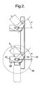
- Fig. 2
- ebenfalls eine schematische Darstellung des Arbeitsprinzip der erfindungsgemäßen Anordnung;
- Fig. 3
- eine erste Möglichkeit zur Lagerung des Doppelhebels in einer Längs- schnittansicht;
- Fig. 4
- eine alternative Lagerungsmöglichkeit in einer ähnlichen Darstellung wie
Fig. 3 ; - Fig. 5
- eine noch andere Möglichkeit für die Lagerung des Doppelhebels ebenfalls in einer Längsschnittansicht;
- Fig. 6A
- in einer perspektivischen Teilansicht den Eckbereich (Abtriebsbereich) eines Türblatts mit dort angeordneter erfindungsgemäßen Verschlußeinrichtung;
- Fig. 6B
- in einer auseinandergezogenen Darstellung den Verschluß der
Fig. 6A ; - Fig. 7A
- in einer perspektivischen Darstellung den Antriebsbereich eines mit erfindungsgemäßer Verschlußeinrichtung versehenen Türblatts;
- Fig. 7B
- in einer auseinandergezogenen Ansicht den Antriebsbereich des erfindungsgemäßen Verschlusses;
- Fig. 8A
- eine Draufsicht auf ein mit erfindungsgemäßer geöffneter Mehrpunktverriegelung versehenes Türblatt;
- Fig. 8B
- eine Schnittdarstellung entlang der Schnittlinie A-A der
Fig. 8A ; - Fig. 8C
- eine Querschnittsansicht durch die recht untere Ecke der Anordnung gemäß
Fig. 8A bzw. 8B; - Fig. 8D
- einen Schnitt entlang der Schnittlinie B-B der
Fig. 8A ; - Fig. 8E
- einerseits auf die rechte untere Ecke der Tür mit erfindungsgemäßem Verschluß der
Fig. 8A , der hier in entriegelter Stellung dargestellt ist; - Fig. 9A
- eine ähnliche Ansicht wie
Fig. 8A einer mit erfindungsgemäßem Verschluß ausgestatteten Tür, wobei der Verschluß hier in verriegelter Stellung dargestellt ist; - Fig. 9B
- einen Schnitt entlang der Linie A-A der
Fig. 9A ; - Fig. 9C
- einen Schnitt durch die rechte untere Ecke des Türblatts gemäß
Fig. 9A bzw. 9B; - Fig. 9D
- eine Schnittdarstellung entlang der Schnittlinie B-B der
Fig. 9A ; und - Fig. 9E
- einen Blick auf die rechte untere Ecke der Tür gemäß
Fig. 9A zur Darstellung des in verschlossener Stellung befindlichen zweiarmigen Hebels. -
Fig.1 läßt in schematisierter Form einen Verschluß 10 zur Mehrpunktverriegelung einer Tür oder eines Wandteils 12 in einem Gehäuse oder Schrank 14, mittels eines - vorzugsweise sicherbaren - Betätigungselements, wie Griffhebel 16, erkennen, umfassend ein mit dem in der Tür oder Wand 12 gelagerten Betätigungselement 16 drehstarr verbundenes, eine Drehbewegung 18 in eine im wesentlichen translatorische Bewegung 20 umwandelndes Kopplungselements 22, das mittels einer Anlenkung 26 mit einer nahe dem Rand der Tür oder Wand 12 verschieblich gelagerten Stange 24 verkoppelt ist, mit welcher Stange 24 wiederum ein oder mehrere Riegelelemente 28 jeweils mittels eines Kopplungselements 22 derart verkoppelt sind, dass sie bei Verschiebung der Stange 24 aus einer ersten Stellung, sieheFig. 8E , in eine zweite Stellung, sieheFig. 1 bzw.Fig. 9E , aus einer verriegelten Position in eine entriegelte Position (oder umgekehrt) gelangen, wobei die Riegelelemente 28 und die Kopplungselemente 22 jeweils durch einen zweiarmigen einstückigen Hebel 22 gebildet werden, dessen zwei Hebelarme 30, 32 einen Winkel von annähernd 135 bzw. 225 Winkelgraden, Bezugszahl 34 bzw. 36, einschließen. - Wie aus den Figuren erkennbar wird, stellt der eine Hebelarm 30 eine Verschlußzunge dar, mit einer Auftaufschräge 38. Der andere Hebelarm 32 ist mit seinem Ende 34 an der Stange 24 angelenkt.
- Mindestens einer der zweiarmigen Hebel 22, 122, 222 ist in drehstarrer Verbindung mit der Antriebswelle 42 eines Betätigungselements 16 verknüpft.
- In diesem Fall übernimmt er auch die Welle 42 die Lagerung des zweiarmigen Hebels, der ansonsten am Kreuzungspunkt der Längsachsen 50, 52 der beiden Hebelarme an der Tür oder Wand 12 oder an einer von dieser Tür oder Wand 12 gehaltenen Träger 44, siehe
Fig. 4 , wie Versteifungsprofil, drehbar gelagert ist. - Der jeweils letzte Doppelhebel 122 einer Stange 24 kann eine Anlenkungsmöglichkeit für eine weitere Mitnehmerstange 124 aufweisen, die in gleicher oder anderer Richtung 124 bzw. 224, insbesondere senkrecht zur den Doppelhebel 222 antreibenden Stange 224 verschieblich ist, siehe die Pfeile 20, 120, 220. An der weiteren Stange, 120, können ebenfalls Doppelhebel 322 angelenkt sein.
- Wie
Fig. 1 erkennen läßt, kann der Doppelhebel 222 einen dritten Hebelarm 46 aufweisen, dessen Achse 48 zu der Achse 50 des anderen Anlenkhebels 132 um z. B. 90 oder 120 Grad gegenüber der Asche 50 versetzt abgeordnet ist und eine weitere Stange 124 antreibt. - Die Anlenkung zwischen einer Stange 24 einerseits und dem doppelarmigen Hebel 122 andererseits kann durch ein Zapfen-Loch-System, siehe die Bezugszahl 54, 56, erfolgen, siehe
Fig. 6A . Alternativ kann die Anlenkung durch Verschraubung oder durch Vernietung erfolgen, die entsprechende Drehmöglichkeiten eröffnet. - Die Lagerung des Doppelhebels 122 erfolgt z B. mittels einer mit Absatz 58 und Ringschulter 60 endender Hülse 62, wobei Durchmesser und Höhe des Absatzes 58 so gewählt sind, dass der Doppelhebel 122 mit geringem Spiel drehbar auf dem Absatz 58 gehalten ist.
- Gemäß
Fig. 3 weist die Hülse 262 eine Gewindebohrung 64 zur Aufnahme eines von der Befestigungsfläche 212 ausgehenden Gewindebolzens 66 einerseits und einer Kopfschraube 68 andererseits auf. - Bei der Ausführungsform der
Fig. 3 überragt der Kopf der Schraube 68 den Absatz 258 derart, dass der Doppelhebel 222 von der Gewindehülse 262 nicht abgleiten kann. - Der Gewindebolzen 66 kann in ein aus Metallblech bestehende Türblatt 212 eingepreßt, eingeschweißt oder, vorzugsweise unter Verwendung einer Dichtung, in das Türblatt eingeschraubt sein, in welchem letzten Falle das Türblatt 212 aus beliebigem Material bestehen kann, z. B. Kunststoff.
- Das Aufschrauben der Gewindehülse 262 wird erleichtert, wenn diese Gewindehülse 262 zumindest teilweise prismatischen Querschnitt aufweist, z. B. seitlich abgeflacht ist oder als Sechskant ausgeführt ist.
- Wie
Fig. 4 zeigt, kann die Hülse 162 auch eine Durchgangshülse darstellen, durch die eine Kopfschraube 168 geführt ist, die in eine Mutter 70, wie Einpreß-, Anschweiß- oder normale Mutter, oder in einen Gewindedurchzug in einer Doppelwand 44, oder einem Winkel oder Rahmen verschraubt ist. - Zwischen Schraubenkopf der Kopfschraube 68 und dem Hebel bzw. der Verschlußzunge 222 kann eine Unterlegschreibe angeordnet sein, in
Fig. 3 nicht dargestellt. - Eine weitere Variante ist in
Fig. 5 dargestellt, wo eine Hülse 362 als Durchgangshülse ausgestaltet ist, durch die ein Gewindebolzen 366 geführt ist, der auf der Befestigungsfläche 12 eingepreßt, verschweißt oder, ggf. mit Dichtung, verschraubt ist, wobei der Doppelhebel bzw. die Verschlußzunge 322 durch eine auf dem Bolzen 366 aufgeschraubte Mutter, wie Stoppmutter 72, ggf. unter Zwischenlage einer Unterlegscheibe, siehe Bezugszahl 74 inFig. 6B , gehalten ist. - In
Fig. 7A ist ein Verschluß zu erkennen, bei dem der Doppelhebel 222 in seinem Lagerbereich einen RücksprungNorsprung 78 zur formschlüssigen Aufnahme eines Mitnehmers 176 oder auch eines Vierkants aufweist, der seinerseits ein Teil eines Verschlußantriebes 80 ist oder von dessen Dorn oder Welle 82 angetrieben ist. - Gemäß
Fig. 7B umfaßt der Verschlußantrieb 80 einen in eine Mulde 84 einklappbaren Verschlußhebel 86, der am Ende der Welle 82 angelenkt ist und optional in eingeklappter Stellung, wie inFig. 7B erkennbar, mit einem Zylinderschloß verriegelbar ist, siehe Bezugszahl 88. - Die Mulde 84 wird auf einem Verschlußgehäuse 90 gehalten, wobei der Gelenkdorn 82 z. B. in einem Verschlußkasten 92 seine Lagerung findet.
- Während
Fig. 6A einen Doppelhebel 122 zeigt, der von der Stange 24 angetrieben wird, ist der inFig. 7A erkennbare Doppelhebel 222 von der Betätigung 86 angetrieben und treibt selbst die Stange 24 an. Der Doppelhebel 122 ist in derFig. 6A von dem Profil 44 gelagert, während beiFig. 7A eine Unterbrechung in dem Profil vorgesehen ist, und der Doppelhebel 222 von der Betätigung gelagert ist. - Die Erfindung ist im Schaltschrankbau gewerblich verwertbar.
-
- 10
- Verschluß
- 12,212
- Tür, Wandteil
- 14
- Schrank, Gehäuse
- 16
- Griffhebel, Betätigungselement
- 18
- Drehbewegung
- 20, 120, 220
- translatorische Bewegung
- 22, 122, 222, 322
- Kupplungselement, Hebel
- 24, 124, 224, 324
- Stange
- 26, 126
- Verkopplung, Anlenkung
- 28
- Riegelelement
- 30,230
- Hebelarm
- 32,232
- Hebelarm
- 34
- Winkel 135 Grad
- 36
- Winkel 225 Grad
- 38
- Auflaufschräge
- 40
- Ende
- 42
- Antriebswelle
- 44
- Träger, Versteifungsprofil
- 46
- dritter Hebelarm
- 48
- Achse
- 50
- Achse
- 52
- Achse
- 54
- Zapen
- 56
- Loch
- 58, 258
- Absatz
- 60,260
- Ringschulter
- 62, 162, 262, 362
- Hülse
- 64
- Gewindebohrung
- 66,366
- Gewindebolzen
- 68, 168
- Kopfschraube
- 70
- Mutter, Gewindedurchzug
- 72, 172
- Stoppmutter
- 74, 174, 274
- Unterlegscheibe
- 76
- Mitnehmer
- 78
- RücksprungNorsprung
- 80
- Verschlußantrieb
- 82
- Dorn, Welle
- 84
- Mulde
- 86
- Verschlußhebel
- 88
- Verriegelung
- 90
- Verschlußgehäuse
- 92
- Verschlußkasten
Claims (17)
- Verschluß (10) zur Mehrpunktverriegelung von Türen (12) oder Wandteilen in Gehäusen (14) oder Schränken, mittels eines - vorzugsweise sicherbaren - Betätigungselements (16), wie Griffhebel, umfassend ein mit dem in der Tür oder Wand (12) gelagerten Betätigungselement (16) drehstarr verbundenes, eine Drehbewegung (18) in eine im wesentlichen translatorische Bewegung (20) umwandelndes Kopplungselement (22), das mit einer nahe dem Rand der Tür oder Wand (12) verschieblich gelagerten Stange (24) verkoppelt ist (26), mit der ihrerseits ein oder mehrere Riegelelemente (28) jeweils mittels eines Kopplungselements (30, 32) derart verkoppelt sind, dass sie bei Verschiebung der Stange (24) aus einer ersten Stellung in eine zweite Stellung aus einer verriegelten Position in eine entriegelte Position (oder umgekehrt) gelangen, wobei die Riegelelemente (28) und die Kopplungselemente (22) jeweils durch einen zweiarmigen einstückigen Hebel (22) gebildet werden, dessen einer Hebelarm (30) eine Verschlußzunge darstellt und dessen anderer Hebelarm (32) mit seinem Ende (40) an der Stange (24) angelenkt ist, wobei die zwei Hebelarme (30, 32) einen Winkel von 120 bis 150, vorzugsweise annähernd 135 (bzw. 225) Winkelgraden einschließen (34, 36), wobei zumindest einer der zweiarmigen Hebel (22, 122, 222, 322) in drehstarrer Verbindung mit der Antriebswelle (42) eines Betätigungselements (60) steht, wobei der zweiarmige Hebel (22) am Kreuzungspunkt der Achsen (48, 50) der beiden Hebelarme (30, 32) an der Tür oder Wand (12) oder an einer von dieser gehaltenen Träger (44), wie Versteifungsprofil, drehbar gelagert ist, dadurch gekennzeichnet, dass der Doppelhebel (22, 122, 222) in seinem Lagerbereich einen Rücksprung/Vorsprung (78) zur formschlüssigen Aufnahme eines Mitnehmers (76) oder Vierkants aufweist, der seinerseits ein Teil eines Verschlußantriebes (80) ist oder von dessen Dorn oder Welle (82) angetrieben ist.
- Verschluß nach Anspruch 1, dadurch gekennzeichnet, dass der (z. B. jeweils letzte) Doppelhebel (222) einer Stange (224) eine Anlenkungsmöglichkeit für eine weitere Mitnehmerstange (124) aufweist, die in gleicher (324) oder anderer Richtung (124), insbesondere senkrecht zur den Doppelhebel antreibenden Stange (224) verschieblich ist.
- Verschluß nach Anspruch 2, dadurch gekennzeichnet, dass an der weiteren Stange (24) ebenfalls Doppelhebel (322) angelenkt sind.
- Verschluß nach einem der Ansprüche 1 bis 3, dadurch gekennzeichnet, dass der Doppelhebel (30, 32) einen dritten Hebelarm (46) aufweist, dessen Achse (48) zu den Achsen (52, 50, 250) der anderen Hebelarme (232) versetzt angeordnet ist und eine weitere Stange antreibt.
- Verschluß nach einem der Ansprüche 1 bis 4, dadurch gekennzeichnet, dass die Anlenkung durch ein Zapfen-Loch-System (54, 56), durch Verschraubung oder durch Vernietung erfolgt.
- Verschluß nach einem der Ansprüche 1 bis 5, dadurch gekennzeichnet, dass die Lagerung des Doppelhebels (22) mittels einer mit Absatz (58) und Ringschulter (60) endender Hülse (62) erfolgt, wobei Durchmesser und Höhe des Absatzes (58) so gewählt sind, dass der Doppelhebel (22) mit geringem Spiel drehbar auf dem Absatz (58) gehalten ist.
- Verschluß nach Anspruch 6, dadurch gekennzeichnet, dass die Hülse (262) eine Gewindebohrung (64) zur Aufnahme eines von der Befestigungsfläche ausgehenden Gewindebolzens (66) einerseits und einer Kopfschraube (68) andererseits aufweist.
- Verschluß nach Anspruch 7, dadurch gekennzeichnet, dass die Gewindehülse zumindest teilweise prismatischen Querschnitt aufweist, wie seitlich abgeflacht oder als Sechskant ausgeführt ist.
- Verschluß nach Anspruch 6 oder 7, dadurch gekennzeichnet, dass der - Gewindebolzen in das aus Metallblech bestehende Türblatt (12) eingepreßt, eingeschweißt oder, vorzugsweise unter Verwendung einer Dichtung, in das Türblatt (12) aus dann beliebigem Material wie Kunststoff eingeschraubt ist.
- Verschluß nach Anspruch 6, dadurch gekennzeichnet, dass die Hülse eine Durchgangshülse ist, durch die eine Kopfschraube geführt ist, die in eine Mutter, wie Einpreß-, Anschweiß- oder normale Mutter, oder in einen Gewindedurchzug (70) in einer Doppelwand oder einem Winkel oder Rahmen (44) verschraubt ist.
- Verschluß nach einem der Ansprüche 6 bis 10, dadurch gekennzeichnet, dass zwischen Schraubenkopf und Hebel eine Unterlegschreibe angeordnet ist.
- Verschluß nach Anspruch 6, dadurch gekennzeichnet, dass die Hülse eine Durchgangshülse ist, durch die ein Gewindebolzen geführt ist, der auf der Befestigungsfläche (12) eingepreßt, verschweißt oder, ggf. mit Dichtung, verschraubt ist, wobei der Doppelhebel (22) durch eine auf dem Bolzen aufgeschraubte Mutter, wie Stoppmutter (72), ggf. unter Zwischenlage einer Unterlegschebe (74) gehalten ist.
- Verschluß nach einem der Ansprüche 1 bis 12, dadurch gekennzeichnet, dass der Verschlußantrieb einen in eine Mulde (84) einklappbaren Verschlußhebel (86) umfaßt, der optional in eingeklappter Stellung verriegelbar (88) ist.
- Verschluß nach Anspruch 13, dadurch gekennzeichnet, dass der Verschlußhebel (86) am Ende der Welle (82) angelenkt ist.
- Verschluß nach Anspruch 13 oder 14, dadurch gekennzeichnet, dass die Mulde (84) auf einem Verschlußgehäuse (90) gehalten ist.
- Verschluß nach Anspruch 15, dadurch gekennzeichnet, dass der Gelenkdorn (82) in einem Verschlußkasten (92) gelagert ist.
- Verschluß nach einem der Ansprüche 1 bis 16, dadurch gekennzeichnet, dass der (Doppel-)Hebel (222) in einer Unterbrechung in dem Profil (44) von der Betätigung gelagert ist.
Applications Claiming Priority (2)
| Application Number | Priority Date | Filing Date | Title |
|---|---|---|---|
| DE202005012859U DE202005012859U1 (de) | 2005-08-16 | 2005-08-16 | Verschluß zur Mehrpunktverriegelung von Türen oder Wandteilen in Gehäusen oder Schränken |
| PCT/EP2006/008003 WO2007020031A1 (de) | 2005-08-16 | 2006-08-12 | Verschluss zur mehrpunktverriegelung von türen oder wandteilen in gehäusen oder schränken |
Publications (2)
| Publication Number | Publication Date |
|---|---|
| EP1917413A1 EP1917413A1 (de) | 2008-05-07 |
| EP1917413B1 true EP1917413B1 (de) | 2009-05-27 |
Family
ID=37459511
Family Applications (1)
| Application Number | Title | Priority Date | Filing Date |
|---|---|---|---|
| EP20060776817 Expired - Lifetime EP1917413B1 (de) | 2005-08-16 | 2006-08-12 | Verschluss zur mehrpunktverriegelung von türen oder wandteilen in gehäusen oder schränken |
Country Status (8)
| Country | Link |
|---|---|
| US (1) | US20090033103A1 (de) |
| EP (1) | EP1917413B1 (de) |
| JP (1) | JP2009504951A (de) |
| CN (1) | CN101243234A (de) |
| AT (1) | ATE432403T1 (de) |
| BR (1) | BRPI0614789A2 (de) |
| DE (3) | DE202005012859U1 (de) |
| WO (1) | WO2007020031A1 (de) |
Families Citing this family (10)
| Publication number | Priority date | Publication date | Assignee | Title |
|---|---|---|---|---|
| US20110148125A1 (en) * | 2009-12-18 | 2011-06-23 | Large Frank J | Lever action door latch |
| DE202013104879U1 (de) | 2013-10-31 | 2013-12-03 | Emka Beschlagteile Gmbh & Co. Kg | Verschlusssystem zur Mehrpunktverriegelung von Türen |
| CN105630099B (zh) * | 2014-11-26 | 2019-04-16 | 英业达科技有限公司 | 服务器箱体总成 |
| FR3066221B1 (fr) * | 2017-05-09 | 2020-07-24 | Comec | Menuiserie comprenant un ouvrant et dispositif de verrouillage de l'ouvrant, et ensemble comprenant une telle menuiserie |
| CN107386493B (zh) * | 2017-07-31 | 2023-09-26 | 新疆乾景建筑工程有限公司 | 一种轻质隔墙板 |
| CN109267853B (zh) * | 2018-10-29 | 2020-12-18 | 北京航天发射技术研究所 | 一种舱盖串锁机构及舱盖系统 |
| DE102019114188A1 (de) * | 2019-05-27 | 2020-12-03 | Emka Beschlagteile Gmbh & Co. Kg | Stangenverschluss |
| CN111119581B (zh) * | 2019-12-27 | 2021-07-09 | 中国航空工业集团公司沈阳飞机设计研究所 | 一种具有多向承载和安全自锁能力的舱门锁闭装置 |
| CN111260845B (zh) * | 2020-01-15 | 2022-05-31 | 深圳市萝趣物联网科技有限公司 | 一种自动售货机 |
| US12560006B2 (en) * | 2022-03-29 | 2026-02-24 | Michael Reilly Design, Llc | Low profile multi-point lock drive |
Family Cites Families (22)
| Publication number | Priority date | Publication date | Assignee | Title |
|---|---|---|---|---|
| US1047900A (en) * | 1912-07-15 | 1912-12-17 | Henry G Voight | Fire-door lock. |
| US1704601A (en) * | 1925-06-30 | 1929-03-05 | Fritz S Hall | Window latch |
| US2315239A (en) * | 1941-03-19 | 1943-03-30 | Young William | Door securing mechanism |
| US2460961A (en) * | 1944-09-29 | 1949-02-08 | Wilson Mfg Company | Quick-acting securing means for watertight doors |
| US2511267A (en) * | 1945-10-09 | 1950-06-13 | Budd Co | Bulkhead door structure |
| US2511268A (en) * | 1946-05-03 | 1950-06-13 | Budd Co | Bulkhead door and the like and fastening means for same |
| US2506553A (en) * | 1946-09-06 | 1950-05-02 | Crane & Breed Casket Company | Casket latch |
| US2666248A (en) * | 1951-09-21 | 1954-01-19 | Crane & Breed Casket Company | Latch for caskets |
| US3362573A (en) * | 1966-05-10 | 1968-01-09 | Metrodynamics Corp | Quick release explosion-proof enclosure |
| DE7534983U (de) * | 1975-11-04 | 1976-05-26 | Kessler, Rudolf, 7000 Stuttgart | Mehrfachverriegelung fuer fluegeltueren an schraenken |
| EP0261267B2 (de) * | 1986-09-25 | 1999-12-15 | Dieter Ramsauer | Stangenverschluss für Blechschranktüren |
| GB8802004D0 (en) * | 1988-01-29 | 1988-02-24 | Gen Electric Co Plc | Sealed cabinet |
| DE9004756U1 (de) * | 1990-04-27 | 1991-08-22 | Ramsauer, Dieter, 5620 Velbert | Mit Zylinderschloßeinrichtung arretierbarer Schwenkhebelverschluß |
| US5086587A (en) * | 1991-01-30 | 1992-02-11 | Andrews Zenas B | Balanced beam latching apparatus |
| EP0552505B1 (de) * | 1992-01-21 | 1994-12-07 | Machinefabriek en Handelmaatschappij Winel B.V. | Türblatt zum Schliessen einer Öffnung und Verriegelungssystem zur Verwendung als Teil davon |
| US5268543A (en) * | 1992-03-17 | 1993-12-07 | S&C Electric Company | Locking arrangement for disconnect switch |
| DE59706645D1 (de) * | 1997-08-29 | 2002-04-18 | Dieter Ramsauer | Verschlussvorrichtung mit horizontaler handhabe |
| FR2770251B1 (fr) * | 1997-10-27 | 1999-12-17 | Ind Du Ponant L | Porte pivotante du type comportant au moins un battant sur lequel sont montees paralleles deux tringles par l'intermediaire de biellettes |
| US6123370A (en) * | 1999-03-31 | 2000-09-26 | Hartwell Corporation | Increased strength dogging mechanism |
| DE19946773C2 (de) * | 1999-09-29 | 2003-06-05 | Rittal Gmbh & Co Kg | Schliesseinrichtung für einen Schaltschrank |
| DE20319136U1 (de) * | 2003-12-10 | 2005-04-28 | Dirak Konstruktionselemente Gmbh & Co. Kg | Verschluß zur Mehrfachverriegelung von Türen oder Wandteilen in Gehäusen oder Schränken |
| TWM268630U (en) * | 2004-12-23 | 2005-06-21 | Inventec Corp | Clamping structure |
-
2005
- 2005-08-16 DE DE202005012859U patent/DE202005012859U1/de not_active Expired - Lifetime
-
2006
- 2006-08-12 DE DE200650003827 patent/DE502006003827D1/de not_active Expired - Lifetime
- 2006-08-12 BR BRPI0614789-5A patent/BRPI0614789A2/pt not_active Application Discontinuation
- 2006-08-12 EP EP20060776817 patent/EP1917413B1/de not_active Expired - Lifetime
- 2006-08-12 US US11/990,548 patent/US20090033103A1/en not_active Abandoned
- 2006-08-12 JP JP2008526419A patent/JP2009504951A/ja not_active Withdrawn
- 2006-08-12 AT AT06776817T patent/ATE432403T1/de not_active IP Right Cessation
- 2006-08-12 WO PCT/EP2006/008003 patent/WO2007020031A1/de not_active Ceased
- 2006-08-12 CN CNA2006800301534A patent/CN101243234A/zh active Pending
- 2006-08-12 DE DE200611001912 patent/DE112006001912A5/de not_active Withdrawn
Also Published As
| Publication number | Publication date |
|---|---|
| WO2007020031A1 (de) | 2007-02-22 |
| US20090033103A1 (en) | 2009-02-05 |
| DE112006001912A5 (de) | 2008-06-19 |
| DE202005012859U1 (de) | 2006-12-28 |
| DE502006003827D1 (de) | 2009-07-09 |
| WO2007020031B1 (de) | 2007-05-03 |
| EP1917413A1 (de) | 2008-05-07 |
| BRPI0614789A2 (pt) | 2011-04-12 |
| JP2009504951A (ja) | 2009-02-05 |
| ATE432403T1 (de) | 2009-06-15 |
| CN101243234A (zh) | 2008-08-13 |
Similar Documents
| Publication | Publication Date | Title |
|---|---|---|
| EP1709270B1 (de) | Klipsbefestigung für die montage von beschlageinrichtungen, wie verschlüsse, scharnierteile, griffe in durchbrüchen in einer dünnen wand | |
| EP2025837B1 (de) | Drehhandhabe für einen Verschluss eines Flügels eines Fensters oder dergleichen sowie Verfahren zur Betätigung des Verschlusses | |
| EP0693602B1 (de) | Versenkbarer Verschluss für links- und rechts angeschlagene Schaltschranktüren | |
| EP1900891A2 (de) | Klapp-Hebelverschluss | |
| EP1857616A2 (de) | Verschluss zur Montage in Durchbrüchen in einer dünnen Wand | |
| DE102013104078B4 (de) | Riegelschloss eines Möbels | |
| DE19742511C2 (de) | Schubstangenverschluß für eine an einem Schaltschrank-Korpus angelenkte Schranktüre | |
| EP0361001B1 (de) | Schlosshaken | |
| EP1917413A1 (de) | Verschluss zur mehrpunktverriegelung von türen oder wandteilen in gehäusen oder schränken | |
| EP0485767B1 (de) | Verschluss für den Flügel, insbesondere Schiebeflügel eines Fensters, einer Tür od.dgl. | |
| EP1179107B1 (de) | Verschlussvorrichtung für türen von ein schmales rahmenprofil aufweisenden gehäusen oder schränken | |
| DE19536906C1 (de) | Verschluß für einen Schrank, insbesondere Schaltschrank | |
| EP4405547A1 (de) | Verschluss | |
| EP2142736B1 (de) | Beschlag für ein fenster, eine tür oder dergleichen | |
| EP3737816B1 (de) | Möbelscharnier, möbelplatte und möbelkorpus | |
| DE202011000675U1 (de) | Schrank, insbesondere Gasflaschenschrank | |
| AT394607B (de) | Mehrfachverriegelung | |
| WO2007131629A1 (de) | Stangenverschluss mit zwei verriegelungsstellungen | |
| DE4200868A1 (de) | Zusatz-schliesseinrichtung fuer fenster | |
| EP0738814A1 (de) | Vorrichtung an einem Türschloss | |
| DE10162707A1 (de) | Drehbetätigungseinrichtung für ein Schaltgetriebe an einem Flügel oder einem festen Rahmen eines Fensters, einer Tür od. dgl. | |
| DE10334592A1 (de) | Anordnung als Teil eines Schließmechanismus | |
| DE3242090C2 (de) | Treibstangenverschluß zum Feststellen des unterschlagenden Flügels von zweiflügeligen Fenstern oder Türen ohne Mittelpfosten in der geschlossenen Stellung | |
| DE60205574T2 (de) | Verriegelungsvorrichtung | |
| DE19644157A1 (de) | Fenster- oder Türbeschlag |
Legal Events
| Date | Code | Title | Description |
|---|---|---|---|
| PUAI | Public reference made under article 153(3) epc to a published international application that has entered the european phase |
Free format text: ORIGINAL CODE: 0009012 |
|
| 17P | Request for examination filed |
Effective date: 20080128 |
|
| AK | Designated contracting states |
Kind code of ref document: A1 Designated state(s): AT BE BG CH CY CZ DE DK EE ES FI FR GB GR HU IE IS IT LI LT LU LV MC NL PL PT RO SE SI SK TR |
|
| RIN1 | Information on inventor provided before grant (corrected) |
Inventor name: HOESCHLER, PETER Inventor name: FRANZ, MARKUS Inventor name: CAPPEL, DENNIS Inventor name: RAMSAUER, DIETER Inventor name: KLASSEN, SAMUEL Inventor name: KOCH, SEBASTIAN |
|
| GRAP | Despatch of communication of intention to grant a patent |
Free format text: ORIGINAL CODE: EPIDOSNIGR1 |
|
| DAX | Request for extension of the european patent (deleted) | ||
| GRAS | Grant fee paid |
Free format text: ORIGINAL CODE: EPIDOSNIGR3 |
|
| GRAA | (expected) grant |
Free format text: ORIGINAL CODE: 0009210 |
|
| AK | Designated contracting states |
Kind code of ref document: B1 Designated state(s): AT BE BG CH CY CZ DE DK EE ES FI FR GB GR HU IE IS IT LI LT LU LV MC NL PL PT RO SE SI SK TR |
|
| REG | Reference to a national code |
Ref country code: GB Ref legal event code: FG4D Free format text: NOT ENGLISH |
|
| REG | Reference to a national code |
Ref country code: CH Ref legal event code: EP |
|
| REG | Reference to a national code |
Ref country code: IE Ref legal event code: FG4D Free format text: LANGUAGE OF EP DOCUMENT: GERMAN |
|
| REF | Corresponds to: |
Ref document number: 502006003827 Country of ref document: DE Date of ref document: 20090709 Kind code of ref document: P |
|
| PG25 | Lapsed in a contracting state [announced via postgrant information from national office to epo] |
Ref country code: PT Free format text: LAPSE BECAUSE OF FAILURE TO SUBMIT A TRANSLATION OF THE DESCRIPTION OR TO PAY THE FEE WITHIN THE PRESCRIBED TIME-LIMIT Effective date: 20090927 Ref country code: LT Free format text: LAPSE BECAUSE OF FAILURE TO SUBMIT A TRANSLATION OF THE DESCRIPTION OR TO PAY THE FEE WITHIN THE PRESCRIBED TIME-LIMIT Effective date: 20090527 Ref country code: FI Free format text: LAPSE BECAUSE OF FAILURE TO SUBMIT A TRANSLATION OF THE DESCRIPTION OR TO PAY THE FEE WITHIN THE PRESCRIBED TIME-LIMIT Effective date: 20090527 |
|
| NLV1 | Nl: lapsed or annulled due to failure to fulfill the requirements of art. 29p and 29m of the patents act | ||
| PG25 | Lapsed in a contracting state [announced via postgrant information from national office to epo] |
Ref country code: SI Free format text: LAPSE BECAUSE OF FAILURE TO SUBMIT A TRANSLATION OF THE DESCRIPTION OR TO PAY THE FEE WITHIN THE PRESCRIBED TIME-LIMIT Effective date: 20090527 Ref country code: NL Free format text: LAPSE BECAUSE OF FAILURE TO SUBMIT A TRANSLATION OF THE DESCRIPTION OR TO PAY THE FEE WITHIN THE PRESCRIBED TIME-LIMIT Effective date: 20090527 Ref country code: IS Free format text: LAPSE BECAUSE OF FAILURE TO SUBMIT A TRANSLATION OF THE DESCRIPTION OR TO PAY THE FEE WITHIN THE PRESCRIBED TIME-LIMIT Effective date: 20090927 Ref country code: PL Free format text: LAPSE BECAUSE OF FAILURE TO SUBMIT A TRANSLATION OF THE DESCRIPTION OR TO PAY THE FEE WITHIN THE PRESCRIBED TIME-LIMIT Effective date: 20090527 Ref country code: LV Free format text: LAPSE BECAUSE OF FAILURE TO SUBMIT A TRANSLATION OF THE DESCRIPTION OR TO PAY THE FEE WITHIN THE PRESCRIBED TIME-LIMIT Effective date: 20090527 Ref country code: SE Free format text: LAPSE BECAUSE OF FAILURE TO SUBMIT A TRANSLATION OF THE DESCRIPTION OR TO PAY THE FEE WITHIN THE PRESCRIBED TIME-LIMIT Effective date: 20090827 |
|
| REG | Reference to a national code |
Ref country code: IE Ref legal event code: FD4D |
|
| PG25 | Lapsed in a contracting state [announced via postgrant information from national office to epo] |
Ref country code: EE Free format text: LAPSE BECAUSE OF FAILURE TO SUBMIT A TRANSLATION OF THE DESCRIPTION OR TO PAY THE FEE WITHIN THE PRESCRIBED TIME-LIMIT Effective date: 20090527 Ref country code: CZ Free format text: LAPSE BECAUSE OF FAILURE TO SUBMIT A TRANSLATION OF THE DESCRIPTION OR TO PAY THE FEE WITHIN THE PRESCRIBED TIME-LIMIT Effective date: 20090527 Ref country code: ES Free format text: LAPSE BECAUSE OF FAILURE TO SUBMIT A TRANSLATION OF THE DESCRIPTION OR TO PAY THE FEE WITHIN THE PRESCRIBED TIME-LIMIT Effective date: 20090907 Ref country code: IE Free format text: LAPSE BECAUSE OF FAILURE TO SUBMIT A TRANSLATION OF THE DESCRIPTION OR TO PAY THE FEE WITHIN THE PRESCRIBED TIME-LIMIT Effective date: 20090527 Ref country code: DK Free format text: LAPSE BECAUSE OF FAILURE TO SUBMIT A TRANSLATION OF THE DESCRIPTION OR TO PAY THE FEE WITHIN THE PRESCRIBED TIME-LIMIT Effective date: 20090527 Ref country code: RO Free format text: LAPSE BECAUSE OF FAILURE TO SUBMIT A TRANSLATION OF THE DESCRIPTION OR TO PAY THE FEE WITHIN THE PRESCRIBED TIME-LIMIT Effective date: 20090527 |
|
| PG25 | Lapsed in a contracting state [announced via postgrant information from national office to epo] |
Ref country code: SK Free format text: LAPSE BECAUSE OF FAILURE TO SUBMIT A TRANSLATION OF THE DESCRIPTION OR TO PAY THE FEE WITHIN THE PRESCRIBED TIME-LIMIT Effective date: 20090527 |
|
| BERE | Be: lapsed |
Owner name: RITTAL G.M.B.H. & CO. KG Effective date: 20090831 Owner name: DIRAK DIETER RAMSAUER KONTRUKTIONSELEMENTE G.M.B. Effective date: 20090831 |
|
| PG25 | Lapsed in a contracting state [announced via postgrant information from national office to epo] |
Ref country code: BG Free format text: LAPSE BECAUSE OF FAILURE TO SUBMIT A TRANSLATION OF THE DESCRIPTION OR TO PAY THE FEE WITHIN THE PRESCRIBED TIME-LIMIT Effective date: 20090827 Ref country code: MC Free format text: LAPSE BECAUSE OF NON-PAYMENT OF DUE FEES Effective date: 20090831 |
|
| PLBE | No opposition filed within time limit |
Free format text: ORIGINAL CODE: 0009261 |
|
| STAA | Information on the status of an ep patent application or granted ep patent |
Free format text: STATUS: NO OPPOSITION FILED WITHIN TIME LIMIT |
|
| 26N | No opposition filed |
Effective date: 20100302 |
|
| REG | Reference to a national code |
Ref country code: FR Ref legal event code: ST Effective date: 20100430 |
|
| PG25 | Lapsed in a contracting state [announced via postgrant information from national office to epo] |
Ref country code: BE Free format text: LAPSE BECAUSE OF NON-PAYMENT OF DUE FEES Effective date: 20090831 |
|
| PG25 | Lapsed in a contracting state [announced via postgrant information from national office to epo] |
Ref country code: FR Free format text: LAPSE BECAUSE OF NON-PAYMENT OF DUE FEES Effective date: 20090831 |
|
| PG25 | Lapsed in a contracting state [announced via postgrant information from national office to epo] |
Ref country code: GR Free format text: LAPSE BECAUSE OF FAILURE TO SUBMIT A TRANSLATION OF THE DESCRIPTION OR TO PAY THE FEE WITHIN THE PRESCRIBED TIME-LIMIT Effective date: 20090828 |
|
| PG25 | Lapsed in a contracting state [announced via postgrant information from national office to epo] |
Ref country code: AT Free format text: LAPSE BECAUSE OF NON-PAYMENT OF DUE FEES Effective date: 20090812 |
|
| PG25 | Lapsed in a contracting state [announced via postgrant information from national office to epo] |
Ref country code: IT Free format text: LAPSE BECAUSE OF FAILURE TO SUBMIT A TRANSLATION OF THE DESCRIPTION OR TO PAY THE FEE WITHIN THE PRESCRIBED TIME-LIMIT Effective date: 20090527 |
|
| REG | Reference to a national code |
Ref country code: CH Ref legal event code: PL |
|
| GBPC | Gb: european patent ceased through non-payment of renewal fee |
Effective date: 20100812 |
|
| PG25 | Lapsed in a contracting state [announced via postgrant information from national office to epo] |
Ref country code: LI Free format text: LAPSE BECAUSE OF NON-PAYMENT OF DUE FEES Effective date: 20100831 Ref country code: CH Free format text: LAPSE BECAUSE OF NON-PAYMENT OF DUE FEES Effective date: 20100831 Ref country code: LU Free format text: LAPSE BECAUSE OF NON-PAYMENT OF DUE FEES Effective date: 20090812 |
|
| PG25 | Lapsed in a contracting state [announced via postgrant information from national office to epo] |
Ref country code: HU Free format text: LAPSE BECAUSE OF FAILURE TO SUBMIT A TRANSLATION OF THE DESCRIPTION OR TO PAY THE FEE WITHIN THE PRESCRIBED TIME-LIMIT Effective date: 20091128 |
|
| PG25 | Lapsed in a contracting state [announced via postgrant information from national office to epo] |
Ref country code: TR Free format text: LAPSE BECAUSE OF FAILURE TO SUBMIT A TRANSLATION OF THE DESCRIPTION OR TO PAY THE FEE WITHIN THE PRESCRIBED TIME-LIMIT Effective date: 20090527 Ref country code: GB Free format text: LAPSE BECAUSE OF NON-PAYMENT OF DUE FEES Effective date: 20100812 |
|
| PG25 | Lapsed in a contracting state [announced via postgrant information from national office to epo] |
Ref country code: CY Free format text: LAPSE BECAUSE OF FAILURE TO SUBMIT A TRANSLATION OF THE DESCRIPTION OR TO PAY THE FEE WITHIN THE PRESCRIBED TIME-LIMIT Effective date: 20090527 |
|
| REG | Reference to a national code |
Ref country code: DE Ref legal event code: R082 Ref document number: 502006003827 Country of ref document: DE Representative=s name: BOEHMERT & BOEHMERT, DE Ref country code: DE Ref legal event code: R082 Ref document number: 502006003827 Country of ref document: DE Representative=s name: STRATMANN, ERNST, DIPL.-ING. DR.-ING., DE |
|
| REG | Reference to a national code |
Ref country code: DE Ref legal event code: R082 Ref document number: 502006003827 Country of ref document: DE Representative=s name: STRATMANN, ERNST, DIPL.-ING. DR.-ING., DE |
|
| REG | Reference to a national code |
Ref country code: DE Ref legal event code: R081 Ref document number: 502006003827 Country of ref document: DE Owner name: DIRAK DIETER RAMSAUER KONSTRUKTIONSELEMENTE GM, DE Free format text: FORMER OWNERS: DIRAK DIETER RAMSAUER KONSTRUKTIONSELEMENTE GMBH, 58256 ENNEPETAL, DE; RITTAL GMBH & CO. KG, 35745 HERBORN, DE Ref country code: DE Ref legal event code: R082 Ref document number: 502006003827 Country of ref document: DE Representative=s name: COHAUSZ & FLORACK PATENT- UND RECHTSANWAELTE P, DE |
|
| PGFP | Annual fee paid to national office [announced via postgrant information from national office to epo] |
Ref country code: DE Payment date: 20220823 Year of fee payment: 17 |
|
| REG | Reference to a national code |
Ref country code: DE Ref legal event code: R119 Ref document number: 502006003827 Country of ref document: DE |
|
| PG25 | Lapsed in a contracting state [announced via postgrant information from national office to epo] |
Ref country code: DE Free format text: LAPSE BECAUSE OF NON-PAYMENT OF DUE FEES Effective date: 20240301 |