EP1916090A1 - Procédé de fabrication de composants en matière synthétique - Google Patents
Procédé de fabrication de composants en matière synthétique Download PDFInfo
- Publication number
- EP1916090A1 EP1916090A1 EP07118945A EP07118945A EP1916090A1 EP 1916090 A1 EP1916090 A1 EP 1916090A1 EP 07118945 A EP07118945 A EP 07118945A EP 07118945 A EP07118945 A EP 07118945A EP 1916090 A1 EP1916090 A1 EP 1916090A1
- Authority
- EP
- European Patent Office
- Prior art keywords
- heating
- bending
- hold
- kunststoffrohteils
- plastic
- Prior art date
- Legal status (The legal status is an assumption and is not a legal conclusion. Google has not performed a legal analysis and makes no representation as to the accuracy of the status listed.)
- Granted
Links
Images


Classifications
-
- B—PERFORMING OPERATIONS; TRANSPORTING
- B29—WORKING OF PLASTICS; WORKING OF SUBSTANCES IN A PLASTIC STATE IN GENERAL
- B29C—SHAPING OR JOINING OF PLASTICS; SHAPING OF MATERIAL IN A PLASTIC STATE, NOT OTHERWISE PROVIDED FOR; AFTER-TREATMENT OF THE SHAPED PRODUCTS, e.g. REPAIRING
- B29C53/00—Shaping by bending, folding, twisting, straightening or flattening; Apparatus therefor
- B29C53/02—Bending or folding
- B29C53/04—Bending or folding of plates or sheets
- B29C53/043—Bending or folding of plates or sheets using rolls or endless belts
-
- B—PERFORMING OPERATIONS; TRANSPORTING
- B29—WORKING OF PLASTICS; WORKING OF SUBSTANCES IN A PLASTIC STATE IN GENERAL
- B29C—SHAPING OR JOINING OF PLASTICS; SHAPING OF MATERIAL IN A PLASTIC STATE, NOT OTHERWISE PROVIDED FOR; AFTER-TREATMENT OF THE SHAPED PRODUCTS, e.g. REPAIRING
- B29C53/00—Shaping by bending, folding, twisting, straightening or flattening; Apparatus therefor
- B29C53/80—Component parts, details or accessories; Auxiliary operations
- B29C53/84—Heating or cooling
-
- B—PERFORMING OPERATIONS; TRANSPORTING
- B29—WORKING OF PLASTICS; WORKING OF SUBSTANCES IN A PLASTIC STATE IN GENERAL
- B29L—INDEXING SCHEME ASSOCIATED WITH SUBCLASS B29C, RELATING TO PARTICULAR ARTICLES
- B29L2031/00—Other particular articles
- B29L2031/762—Household appliances
- B29L2031/7622—Refrigerators
Definitions
- the invention relates to a device for producing plastic components, in particular of plastic plates, with at least one heating device for heating the plastic component, with at least one molding surface having at least one support point, and with at least one pressure roller for pressing the plastic component to the molding surface, wherein the Pressure roller is freely rotatably mounted on a movable support.
- Multilayer plastic panels can be used in many ways in the art because of their special properties and in particular because of their good thermal insulation.
- a limitation for the application so far is that components with curved surfaces are difficult to produce adequately.
- the plastic plate is placed on a female mold half and pressed by a male mold half into the cavities. During this manufacturing process, however, there are locally high voltages, which lead to microcracks in the component, so that a visually attractive shape and high quality can not be achieved.
- plastic plates that exist as a composite material of different thermoplastics, difficult to work in shaping processes.
- a method and apparatus for bending profiled sheets of thermoplastic material is known.
- the plate is placed between an adjustable to any bending radii fixed and a freely movable template with the same profile and heated in the bending area to softening temperature.
- the freely movable template is pressed starting from the stationary with the stencil engaging end over the bending area continuously to the stationary template until the desired bending angle is reached and kept until the plate with it in positive engagement.
- the pressing of the movable template is carried out with a running in a guide pressure roller whose drive is actuated by the pivoting between the stencil heater.
- thermoplastic composite components a method for producing reinforced thermoplastic composite components is known, wherein a plastic sheet is heated above the softening point and is pressed by pressure rolling on a bending tool, wherein the plastic sheet is bent into the shape of the bending tool.
- the JP 53-144976 A describes a method for bending plastic laminates, wherein for bending small radii the laminate is pressed by means of movable pressure rollers to a bending tool.
- the EP 0 392 047 A1 discloses a method and an apparatus for hot-forming a synthetic resin laminated board, wherein not only the actual bending pressure is applied to the sheet edge area to be bent during the entire bending process, but during the application of this bending pressure at the same time a train is applied to the various laminate layers in the direction of the free edge of the plate ,
- the JP 07-195509 A It aims at a deep-drawing process and not at a bending process. In this system, the entire plate is heated and then pulled over a mold.
- the known methods have the disadvantage that only a minor surface quality of the bent plastic part can be achieved, since it can very easily lead to surface defects during heating and bending.
- this is achieved in that the heating process, the bending process and / or the cooling process is temperature-controlled, wherein preferably at least two zones of the bending region are heated and / or cooled differently.
- the plastic component is clamped during the warm-up process in the region of the heating device and pressed by a holding-down device to the heating device, wherein only locally in the bending region a locally very limited heating of the plastic material takes place.
- the plastic component is surface-friendly transported by suction pads of the blank holder to the bending tool and brought by the pressure rollers to the predetermined shape.
- the plastic component is pressed by negative pressure to the surface of the bending tool, so that damage as a result of shearing movement can be avoided.
- the plastic plate can be locally heated or cooled during the bending process.
- the plastic component during heating and / or during the bending process can be fixed by a retaining means.
- the plastic component can be fixed during heating by at least one movable, preferably beam-shaped hold-down device, the hold-down presses the plastic component against a preferably bar-shaped stationary heater, preferably the longitudinal axis of the hold-down unit and the longitudinal axis of the heater substantially parallel are arranged to each other and parallel to a defined bending region of the plastic component.
- a gentle transport of the plastic component between the heating device and the bending tool can be realized in that the holding-down device has at least one suction gripper on the side facing the plastic component, which is connected to a suction air connection via at least one vacuum channel.
- the hold-down unit has at least one cooling channel.
- the heating device on the side facing the plastic component has a slit diaphragm with at least one slot for heating the bending region of the plastic component.
- the width of the slots defines the warm-up area of the plastic component.
- the width of the slots corresponds essentially to the width of the bending area plus two times the wall thickness.
- the hold-down device In order to prevent the heat from being dissipated via the hold-down device, provision is made for the hold-down device to have a slotted aperture with at least one slot-shaped opening or groove on the side facing the plastic component, the slot-shaped opening or groove facing one another during the heating of the plastic component arranged the slot of the heater and wherein preferably the width of the slot-shaped opening or recess corresponds to the width of the slot of the heater.
- a selective heating of the plastic component can be achieved when the heating device - viewed in the direction of the longitudinal axis of the heater - at least two separately controllable heating zones. It is advantageous for accurate temperature control when the heater has at least one cooling channel.
- the heating device preferably has at least one contactless heating element, for example a ceramic heating element, a quartz heater or an infrared radiator. Alternatively, the use of contact heaters is possible.
- At least one bending tool forming the molding surface has at least one heating and / or cooling device, wherein preferably the bending tool has at least two separately heated or cooled temperature zones.
- the bending tool has at least one opening in the mold surface vacuum channel, which is connectable to a vacuum port. As a result, scratches on the surface due to shearing movements during the bending process can be effectively avoided.
- An exact shaping can be achieved if the pressure rollers are movable by a multi-axis NC drive system.
- Drive system including pressure rollers and tool unit can be arranged in a bending module.
- Heinz drivenen can be arranged side by side in a heating module.
- several hold-down can be arranged in a movable hold-down unit.
- the bending module 2 consists of a tool unit 4, pressure rollers 5 and a multi-axis drive system 6 for the movement of the pressure rollers 5 on the carrier 37th
- the drive system 6 has a horizontal axis system 6a which can be moved horizontally in the x direction and an axis system 6b which can be moved vertically in the z direction.
- a support bar 9 is arranged for the plastic component 10 to be processed.
- the support bar 9 has vacuum ports connected to suction openings 11, via which the plastic component 10 can be sucked and fixed.
- the heating module 3 consists of bar-shaped heating devices 12, on which the plastic component 10 to be heated can be pressed by a hold-down unit 13 with beam-shaped hold-downs 14.
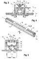
- the heater 12 is shown in detail in FIGS. 4 and 5.
- the heating device 12 consists of a housing 15, in which, for example, ceramic heating elements 16 and optionally reflectors 17 are arranged for the heating elements 16.
- cooling channels 18 of a cooling circuit are arranged in the walls of the housing 15 .
- a slit 19 is provided with one or more slots 20.
- the slots 20 define the bending areas 36 of the plastic component 10.
- the hold-down unit 13 has bar-shaped hold-downs 14, whose longitudinal axes 14a are arranged parallel to the longitudinal axes 12a of the heating device 12.
- the hold-down unit 13 is displaceable in the vertical direction z and in the horizontal direction x and serves to press and fix the plastic component 10 to the heating device 12 during the heating process. This ensures a positionally accurate heating of the plastic component 10 in the bending areas.
- Each holding-down device 14 has, on the surface 14b facing the heating device 12, grooves 33 whose width b 1 , b 2 corresponds to the slot widths B 1 , B 2 of the slots 20 of the slit diaphragm 19 of the respective heating device 12.
- the depth t of the grooves 33 is advantageously greater than the width b 1 , b 2 formed.
- each hold-down 14 For temperature control of each hold-down 14 are arranged in these cooling channels 21 of a cooling circuit.
- Each hold-down 14 is further equipped with suction pads 22, which are connected via vacuum channels 23 with a suction air connection 24.
- the suction pads 22 allow the heated plastic component 10 to be fed to the tool unit 4 to begin the bending operation.
- the heating module 3 has two heating devices 12 arranged spaced apart from one another in order to simultaneously heat a plurality of, in the present case four, bending regions in one working step.
- the hold-down unit 13 in this case also has two hold-downs 14 whose spacing corresponds to that of the heating devices 12.
- the hold-down 14 are connected to each other via bars 25.
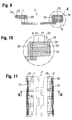
- the tool unit 4 in the exemplary embodiment consists of the bending tools 7, 8, as shown in FIGS. 8 to 11.
- Each bending tool 7, 8 has suction openings 26, which are connected to vacuum channels 27, on the molding surface 34 facing the plastic component 10 to be machined.
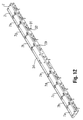
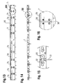
- the suction openings 26 can be designed as elongated grooves or as bores (FIGS. 12 and 16).
- the suction openings 26 are surrounded by sealing channels 28 for receiving sealing elements not shown.
- the vacuum channels 27 lead to vacuum connections 29. To remove the plastic component 10, the bending tools 7, 8 can be moved relative to each other.
- the temperature of the bending tools 7, 8 can be regulated.
- the bending tool 7 is divided into individual temperature zones 7a, 7b, 7c,... 7i, the temperature zones 7a,... 7i being thermally separated from one another by insulating plates 30.
- Each temperature zone 7a,... 7i has a temperature sensor 31 and connections 32 for cooling and / or heating devices for controlling the temperature of the temperature zones 7a,... 7i.
- the well-defined heating of the bending areas 36 is effected by the bar-shaped heating devices 12, which have built-in sequential heating elements 16 which define individual heating areas. Each of these heating areas can be temperature-controlled separately, thereby counteracting a later distortion of the bent parts. By means of this structure, it is possible to produce an arbitrary temperature distribution between the edge and the center of the plastic component 10 over the entire heating zone.
- the well-defined heating range is brought either to the bending radius matching slot 20 of the slit 19 (contactless heaters) or a precisely contoured contact heating to a material-specific bending temperature. typically, are the heating temperatures on, for example, formed by a plastic plate plastic component 10 between about 100 ° C and 220 ° C.
- the hold-down 14 can be used simultaneously as a gripping device and serve for pinpoint transport of the heated plastic plate 10 on the support point 12 of the tool unit 4.
- the heating device 12 and the hold-down 14 are also kept by a tempering always on an accurate process temperature and thus guarantee a reliable production of the plastic component 10 with minimized rejects.
- the heated plastic plate 10 is transported by the integrated in the hold-down pads 14 suction pad 22 on the bending tool 7, 8 pinpoint to the support point 12 and stored. By integrated into the bending tool 7, 8 vacuum channels 27, or vacuum zones, the heated plastic plate 10 is clean and accurately positioned on the bending tool 7, 8 held.
- a pressing device which consists of rotatably mounted pressure rollers 6, presses the heated plastic plate 10 against the molding surfaces of the bending tools 7, 8.
- the applied vacuum in the bending regions 36 holds the plastic component 10 in position and allows it to cool exactly in the predetermined shape.
- the pressure rollers 5 are freely rotatably mounted and can also be fixed by a braking device.
- the trajectory of the pressure rollers 5 is chosen to match the bending tool 7, 8 and is realized by an NC drive system 6.
- the NC drive system 6 has the great advantage that by simply exchanging the form-relevant components another molding can be generated by simple means.
- the pressure roller 5 is further provided with a sheath to protect the surface of the plastic component 10, wherein the material of the sheath is chosen so that a long service life is achieved and that possibly by the elasticity of the sheath minor errors of the plastic component 10 can be compensated.
- the method and the device are particularly suitable for thermoplastic sheets. Furthermore, many possibilities arise through the use of coextruded plates, which consist for example of the following materials: PS (polystyrene), HIPS (high impact polystyrene), ABS (acrylonitrile-butadiene-styrene), PMMA (polymethyl ether acrylate), PE ( Polyethylene), EVOH (ethylene vinyl alcohol copolymer), PP (polypropylene, also with fillers).
- the plate thickness may for example be between 0.5 mm and 10 mm.
- the plastic component 10 is not damaged even with relatively strong deformations, so that the high quality of the surfaces is completely retained.
- the outer casing or the doors of refrigerators made entirely of plastic so that the use of steel can be largely avoided.
- Refrigerators produced in this way are recyclable, inexpensive and can be produced without paint and also have a lower weight. There are also other possibilities for the design.
Landscapes
- Engineering & Computer Science (AREA)
- Mechanical Engineering (AREA)
- Shaping Of Tube Ends By Bending Or Straightening (AREA)
- Extrusion Moulding Of Plastics Or The Like (AREA)
- Compositions Of Macromolecular Compounds (AREA)
- Processing And Handling Of Plastics And Other Materials For Molding In General (AREA)
- Processes Of Treating Macromolecular Substances (AREA)
Applications Claiming Priority (1)
| Application Number | Priority Date | Filing Date | Title |
|---|---|---|---|
| AT0180606A AT505501B1 (de) | 2006-10-25 | 2006-10-25 | Verfahren zur herstellung von kunststoffbauteilen |
Publications (3)
| Publication Number | Publication Date |
|---|---|
| EP1916090A1 true EP1916090A1 (fr) | 2008-04-30 |
| EP1916090B1 EP1916090B1 (fr) | 2009-11-18 |
| EP1916090B8 EP1916090B8 (fr) | 2010-02-03 |
Family
ID=38981564
Family Applications (1)
| Application Number | Title | Priority Date | Filing Date |
|---|---|---|---|
| EP07118945A Not-in-force EP1916090B8 (fr) | 2006-10-25 | 2007-10-22 | Procédé de fabrication de composants en matière synthétique |
Country Status (3)
| Country | Link |
|---|---|
| EP (1) | EP1916090B8 (fr) |
| AT (2) | AT505501B1 (fr) |
| DE (1) | DE502007002019D1 (fr) |
Cited By (2)
| Publication number | Priority date | Publication date | Assignee | Title |
|---|---|---|---|---|
| WO2010149513A2 (fr) | 2009-06-22 | 2010-12-29 | BSH Bosch und Siemens Hausgeräte GmbH | Appareil ménager pourvu d'un élément en plastique et procédé de fabrication d'un tel élément en plastique |
| US20190291372A1 (en) * | 2018-03-22 | 2019-09-26 | General Electric Company | Methods for Manufacturing Wind Turbine Rotor Blade Components |
Citations (8)
| Publication number | Priority date | Publication date | Assignee | Title |
|---|---|---|---|---|
| GB996025A (en) | 1962-05-16 | 1965-06-23 | Bakelite Ltd | Method and apparatus for the heat forming of synthetic resinous sheet material |
| US3229489A (en) * | 1961-07-17 | 1966-01-18 | Huet Andre | Process and apparatus for bending tubes |
| JPS53144976A (en) | 1977-05-24 | 1978-12-16 | Fuji Polymer Ind | Curve processing method of laminated plate |
| EP0141604A2 (fr) | 1983-11-07 | 1985-05-15 | Imperial Chemical Industries Plc | Procédé pour le formage de matériau composite thermoplastique renforcé |
| DD276651A1 (de) | 1988-11-03 | 1990-03-07 | Gartenbau Technik Berlin Veb K | Verfahren und vorrichtung zum biegen von profilierten platten aus thermoplastischem material |
| EP0392047A1 (fr) | 1989-04-12 | 1990-10-17 | Karl Winkler | Procédé et appareil pour déformer à chaud des laminés en résines synthétiques |
| JPH07195509A (ja) | 1993-12-28 | 1995-08-01 | Tsutsunaka Plast Ind Co Ltd | 樹脂シートの熱成形装置および熱成形方法 |
| DE19630227C1 (de) | 1996-07-26 | 1997-12-04 | Berg Bernd | Vorrichtung zum Ab- bzw. Umkanten von Kunststoffplatten, insbesondere Acrylglasplatten |
-
2006
- 2006-10-25 AT AT0180606A patent/AT505501B1/de not_active IP Right Cessation
-
2007
- 2007-10-22 AT AT07118945T patent/ATE448935T1/de active
- 2007-10-22 EP EP07118945A patent/EP1916090B8/fr not_active Not-in-force
- 2007-10-22 DE DE502007002019T patent/DE502007002019D1/de active Active
Patent Citations (8)
| Publication number | Priority date | Publication date | Assignee | Title |
|---|---|---|---|---|
| US3229489A (en) * | 1961-07-17 | 1966-01-18 | Huet Andre | Process and apparatus for bending tubes |
| GB996025A (en) | 1962-05-16 | 1965-06-23 | Bakelite Ltd | Method and apparatus for the heat forming of synthetic resinous sheet material |
| JPS53144976A (en) | 1977-05-24 | 1978-12-16 | Fuji Polymer Ind | Curve processing method of laminated plate |
| EP0141604A2 (fr) | 1983-11-07 | 1985-05-15 | Imperial Chemical Industries Plc | Procédé pour le formage de matériau composite thermoplastique renforcé |
| DD276651A1 (de) | 1988-11-03 | 1990-03-07 | Gartenbau Technik Berlin Veb K | Verfahren und vorrichtung zum biegen von profilierten platten aus thermoplastischem material |
| EP0392047A1 (fr) | 1989-04-12 | 1990-10-17 | Karl Winkler | Procédé et appareil pour déformer à chaud des laminés en résines synthétiques |
| JPH07195509A (ja) | 1993-12-28 | 1995-08-01 | Tsutsunaka Plast Ind Co Ltd | 樹脂シートの熱成形装置および熱成形方法 |
| DE19630227C1 (de) | 1996-07-26 | 1997-12-04 | Berg Bernd | Vorrichtung zum Ab- bzw. Umkanten von Kunststoffplatten, insbesondere Acrylglasplatten |
Cited By (5)
| Publication number | Priority date | Publication date | Assignee | Title |
|---|---|---|---|---|
| WO2010149513A2 (fr) | 2009-06-22 | 2010-12-29 | BSH Bosch und Siemens Hausgeräte GmbH | Appareil ménager pourvu d'un élément en plastique et procédé de fabrication d'un tel élément en plastique |
| DE102009027075A1 (de) | 2009-06-22 | 2010-12-30 | BSH Bosch und Siemens Hausgeräte GmbH | Haushaltsgerät mit einem Kunststoffbauteil sowie Verfahren zur Herstellung eines solchen Kunststoffbauteils |
| DE102009027075B4 (de) * | 2009-06-22 | 2012-12-27 | BSH Bosch und Siemens Hausgeräte GmbH | Haushaltsgerät mit einem Kunststoffbauteil sowie Verfahren zur Herstellung eines solchen Kunststoffbauteils |
| US20190291372A1 (en) * | 2018-03-22 | 2019-09-26 | General Electric Company | Methods for Manufacturing Wind Turbine Rotor Blade Components |
| US11738530B2 (en) * | 2018-03-22 | 2023-08-29 | General Electric Company | Methods for manufacturing wind turbine rotor blade components |
Also Published As
| Publication number | Publication date |
|---|---|
| EP1916090B1 (fr) | 2009-11-18 |
| ATE448935T1 (de) | 2009-12-15 |
| AT505501A1 (de) | 2009-01-15 |
| AT505501B1 (de) | 2010-08-15 |
| EP1916090B8 (fr) | 2010-02-03 |
| DE502007002019D1 (de) | 2009-12-31 |
Similar Documents
| Publication | Publication Date | Title |
|---|---|---|
| EP3439850B1 (fr) | Procédé et outil de formage pour former à chaud un matériau stratifié thermoplastique plan | |
| DE112009004261B4 (de) | Greiferfinger, Greiferwerkzeug und Verfahren zum Justieren eines Greiferwerkzeugs | |
| DE102011012499B4 (de) | Vorrichtung und Verfahren zum Herstellen eines Faserverbundwerkstückes | |
| EP2293909B1 (fr) | Procédé et dispositif de chauffage pour le thermoformage | |
| DE112011102398B4 (de) | Verfahren zum Formen eines Stahlblechs durch Heißpressen | |
| DE10333161A1 (de) | Innenausstattungskomponenten von Kraftfahrzeugen mit einem definierten Oberflächenprofil | |
| DE102018202473B4 (de) | Haltevorrichtung zum Halten von Verbundwerkstoffplatten, Werkzeug und Verfahren | |
| EP0629487A1 (fr) | Procédé et dispositif pour fabriquer des articles laminés en matière plastique | |
| EP1362744B1 (fr) | Elément de construction en matière synthétique, en particulier pour automobile, et son procédé de fabrication | |
| AT518882B1 (de) | Formwerkzeug für eine Formgebungsmaschine | |
| EP1916090B1 (fr) | Procédé de fabrication de composants en matière synthétique | |
| WO2002094544A1 (fr) | Panneau composite a compartiments creux et procede de fabrication | |
| DE102008048298A1 (de) | Verfahren und Vorrichtung zum Prägen von Mikrostrukturen in Kunststoffoberflächen | |
| DE102010001559A1 (de) | Herstellungsverfahren für ein Verkleidungsteil eines Fahrzeugs, entsprechende Vorrichtung sowie Verkleidungsteil | |
| DE102004019293A1 (de) | Verfahren zur Formung von Kunstoffplatten | |
| EP2692504B1 (fr) | Chauffage de contact intégré pour des tapis liés par thermoplastie dans un outil de moulage par injection | |
| DE4423551A1 (de) | Preß-Formgebungsverfahren sowie Vorrichtung zur Durchführung des Verfahrens | |
| DE4108236C1 (en) | Prodn. of highly accurate and/or polished surfaces - involves warming plastic component to plasticise and form it in press tool | |
| EP1410895B1 (fr) | Dispositif pour thermoformage forme avec une membrane et système de chauffage ou réfroidissement | |
| AT512718B1 (de) | Verfahren und Vorrichtung zum Biegen einer Ecke in ein Profil aus thermoplastischem Grundmaterial | |
| WO2019206448A1 (fr) | Procédé, dispositif et outil de formage permettant de thermoformer un film plat ainsi qu'installation permettant de préparer des produits semi-finis et des produits | |
| DE102013109686A1 (de) | Verfahren und Vorrichtung zur Herstellung von Verbindungsbereichen von Verbundblechen | |
| DE2039291A1 (de) | Verfahren und Vorrichtung zur Herstellung eines Hohlkoerpers als Bauteil fuer Moebel u.dgl. | |
| DE102016120064A1 (de) | Verfahren und Vorrichtung zum thermischen, flächigen Verschweißen mehrerer Werkstoffplatten | |
| DE4112567C2 (de) | Verfahren und Vorrichtung zur Herstellung eines Formteils |
Legal Events
| Date | Code | Title | Description |
|---|---|---|---|
| PUAI | Public reference made under article 153(3) epc to a published international application that has entered the european phase |
Free format text: ORIGINAL CODE: 0009012 |
|
| AK | Designated contracting states |
Kind code of ref document: A1 Designated state(s): AT BE BG CH CY CZ DE DK EE ES FI FR GB GR HU IE IS IT LI LT LU LV MC MT NL PL PT RO SE SI SK TR |
|
| AX | Request for extension of the european patent |
Extension state: AL BA HR MK RS |
|
| 17P | Request for examination filed |
Effective date: 20080627 |
|
| 17Q | First examination report despatched |
Effective date: 20080724 |
|
| AKX | Designation fees paid |
Designated state(s): AT BE BG CH CY CZ DE DK EE ES FI FR GB GR HU IE IS IT LI LT LU LV MC MT NL PL PT RO SE SI SK TR |
|
| GRAP | Despatch of communication of intention to grant a patent |
Free format text: ORIGINAL CODE: EPIDOSNIGR1 |
|
| GRAS | Grant fee paid |
Free format text: ORIGINAL CODE: EPIDOSNIGR3 |
|
| GRAA | (expected) grant |
Free format text: ORIGINAL CODE: 0009210 |
|
| AK | Designated contracting states |
Kind code of ref document: B1 Designated state(s): AT BE BG CH CY CZ DE DK EE ES FI FR GB GR HU IE IS IT LI LT LU LV MC MT NL PL PT RO SE SI SK TR |
|
| REG | Reference to a national code |
Ref country code: CH Ref legal event code: EP |
|
| RAP2 | Party data changed (patent owner data changed or rights of a patent transferred) |
Owner name: PROTEX PLASTICS GMBH |
|
| REG | Reference to a national code |
Ref country code: IE Ref legal event code: FG4D |
|
| REF | Corresponds to: |
Ref document number: 502007002019 Country of ref document: DE Date of ref document: 20091231 Kind code of ref document: P |
|
| NLT2 | Nl: modifications (of names), taken from the european patent patent bulletin |
Owner name: PROTEX PLASTICS GMBH Effective date: 20091209 |
|
| REG | Reference to a national code |
Ref country code: CH Ref legal event code: NV Representative=s name: ISLER & PEDRAZZINI AG Ref country code: CH Ref legal event code: PFA Owner name: PROTEX PLASTICS GMBH Free format text: PROTEX PLASTICS GMBH#SCHILLERSTRASSE 10#5700 ZELL AM SEE (AT) -TRANSFER TO- PROTEX PLASTICS GMBH#GEWERBESTRASSE 9#5671 BRUCK (AT) |
|
| REG | Reference to a national code |
Ref country code: NL Ref legal event code: T3 |
|
| LTIE | Lt: invalidation of european patent or patent extension |
Effective date: 20091118 |
|
| PG25 | Lapsed in a contracting state [announced via postgrant information from national office to epo] |
Ref country code: SE Free format text: LAPSE BECAUSE OF FAILURE TO SUBMIT A TRANSLATION OF THE DESCRIPTION OR TO PAY THE FEE WITHIN THE PRESCRIBED TIME-LIMIT Effective date: 20091118 Ref country code: IS Free format text: LAPSE BECAUSE OF FAILURE TO SUBMIT A TRANSLATION OF THE DESCRIPTION OR TO PAY THE FEE WITHIN THE PRESCRIBED TIME-LIMIT Effective date: 20100318 Ref country code: ES Free format text: LAPSE BECAUSE OF FAILURE TO SUBMIT A TRANSLATION OF THE DESCRIPTION OR TO PAY THE FEE WITHIN THE PRESCRIBED TIME-LIMIT Effective date: 20100228 Ref country code: FI Free format text: LAPSE BECAUSE OF FAILURE TO SUBMIT A TRANSLATION OF THE DESCRIPTION OR TO PAY THE FEE WITHIN THE PRESCRIBED TIME-LIMIT Effective date: 20091118 Ref country code: PT Free format text: LAPSE BECAUSE OF FAILURE TO SUBMIT A TRANSLATION OF THE DESCRIPTION OR TO PAY THE FEE WITHIN THE PRESCRIBED TIME-LIMIT Effective date: 20100318 Ref country code: LT Free format text: LAPSE BECAUSE OF FAILURE TO SUBMIT A TRANSLATION OF THE DESCRIPTION OR TO PAY THE FEE WITHIN THE PRESCRIBED TIME-LIMIT Effective date: 20091118 |
|
| PG25 | Lapsed in a contracting state [announced via postgrant information from national office to epo] |
Ref country code: LV Free format text: LAPSE BECAUSE OF FAILURE TO SUBMIT A TRANSLATION OF THE DESCRIPTION OR TO PAY THE FEE WITHIN THE PRESCRIBED TIME-LIMIT Effective date: 20091118 Ref country code: SI Free format text: LAPSE BECAUSE OF FAILURE TO SUBMIT A TRANSLATION OF THE DESCRIPTION OR TO PAY THE FEE WITHIN THE PRESCRIBED TIME-LIMIT Effective date: 20091118 Ref country code: CY Free format text: LAPSE BECAUSE OF FAILURE TO SUBMIT A TRANSLATION OF THE DESCRIPTION OR TO PAY THE FEE WITHIN THE PRESCRIBED TIME-LIMIT Effective date: 20091118 Ref country code: PL Free format text: LAPSE BECAUSE OF FAILURE TO SUBMIT A TRANSLATION OF THE DESCRIPTION OR TO PAY THE FEE WITHIN THE PRESCRIBED TIME-LIMIT Effective date: 20091118 |
|
| REG | Reference to a national code |
Ref country code: IE Ref legal event code: FD4D |
|
| PG25 | Lapsed in a contracting state [announced via postgrant information from national office to epo] |
Ref country code: RO Free format text: LAPSE BECAUSE OF FAILURE TO SUBMIT A TRANSLATION OF THE DESCRIPTION OR TO PAY THE FEE WITHIN THE PRESCRIBED TIME-LIMIT Effective date: 20091118 Ref country code: IE Free format text: LAPSE BECAUSE OF FAILURE TO SUBMIT A TRANSLATION OF THE DESCRIPTION OR TO PAY THE FEE WITHIN THE PRESCRIBED TIME-LIMIT Effective date: 20091118 Ref country code: EE Free format text: LAPSE BECAUSE OF FAILURE TO SUBMIT A TRANSLATION OF THE DESCRIPTION OR TO PAY THE FEE WITHIN THE PRESCRIBED TIME-LIMIT Effective date: 20091118 Ref country code: BG Free format text: LAPSE BECAUSE OF FAILURE TO SUBMIT A TRANSLATION OF THE DESCRIPTION OR TO PAY THE FEE WITHIN THE PRESCRIBED TIME-LIMIT Effective date: 20100218 Ref country code: DK Free format text: LAPSE BECAUSE OF FAILURE TO SUBMIT A TRANSLATION OF THE DESCRIPTION OR TO PAY THE FEE WITHIN THE PRESCRIBED TIME-LIMIT Effective date: 20091118 |
|
| PG25 | Lapsed in a contracting state [announced via postgrant information from national office to epo] |
Ref country code: SK Free format text: LAPSE BECAUSE OF FAILURE TO SUBMIT A TRANSLATION OF THE DESCRIPTION OR TO PAY THE FEE WITHIN THE PRESCRIBED TIME-LIMIT Effective date: 20091118 Ref country code: CZ Free format text: LAPSE BECAUSE OF FAILURE TO SUBMIT A TRANSLATION OF THE DESCRIPTION OR TO PAY THE FEE WITHIN THE PRESCRIBED TIME-LIMIT Effective date: 20091118 |
|
| PLBE | No opposition filed within time limit |
Free format text: ORIGINAL CODE: 0009261 |
|
| STAA | Information on the status of an ep patent application or granted ep patent |
Free format text: STATUS: NO OPPOSITION FILED WITHIN TIME LIMIT |
|
| 26N | No opposition filed |
Effective date: 20100819 |
|
| PG25 | Lapsed in a contracting state [announced via postgrant information from national office to epo] |
Ref country code: GR Free format text: LAPSE BECAUSE OF FAILURE TO SUBMIT A TRANSLATION OF THE DESCRIPTION OR TO PAY THE FEE WITHIN THE PRESCRIBED TIME-LIMIT Effective date: 20100219 |
|
| BERE | Be: lapsed |
Owner name: PROTEX PLASTICS GMBH Effective date: 20101031 |
|
| PG25 | Lapsed in a contracting state [announced via postgrant information from national office to epo] |
Ref country code: MC Free format text: LAPSE BECAUSE OF NON-PAYMENT OF DUE FEES Effective date: 20101031 |
|
| PG25 | Lapsed in a contracting state [announced via postgrant information from national office to epo] |
Ref country code: FR Free format text: LAPSE BECAUSE OF NON-PAYMENT OF DUE FEES Effective date: 20101102 |
|
| REG | Reference to a national code |
Ref country code: FR Ref legal event code: ST Effective date: 20110630 |
|
| PG25 | Lapsed in a contracting state [announced via postgrant information from national office to epo] |
Ref country code: BE Free format text: LAPSE BECAUSE OF NON-PAYMENT OF DUE FEES Effective date: 20101031 |
|
| PG25 | Lapsed in a contracting state [announced via postgrant information from national office to epo] |
Ref country code: IT Free format text: LAPSE BECAUSE OF NON-PAYMENT OF DUE FEES Effective date: 20101022 Ref country code: MT Free format text: LAPSE BECAUSE OF FAILURE TO SUBMIT A TRANSLATION OF THE DESCRIPTION OR TO PAY THE FEE WITHIN THE PRESCRIBED TIME-LIMIT Effective date: 20091118 |
|
| GBPC | Gb: european patent ceased through non-payment of renewal fee |
Effective date: 20111022 |
|
| PG25 | Lapsed in a contracting state [announced via postgrant information from national office to epo] |
Ref country code: GB Free format text: LAPSE BECAUSE OF NON-PAYMENT OF DUE FEES Effective date: 20111022 |
|
| PG25 | Lapsed in a contracting state [announced via postgrant information from national office to epo] |
Ref country code: HU Free format text: LAPSE BECAUSE OF FAILURE TO SUBMIT A TRANSLATION OF THE DESCRIPTION OR TO PAY THE FEE WITHIN THE PRESCRIBED TIME-LIMIT Effective date: 20100519 Ref country code: LU Free format text: LAPSE BECAUSE OF NON-PAYMENT OF DUE FEES Effective date: 20101022 |
|
| PG25 | Lapsed in a contracting state [announced via postgrant information from national office to epo] |
Ref country code: TR Free format text: LAPSE BECAUSE OF FAILURE TO SUBMIT A TRANSLATION OF THE DESCRIPTION OR TO PAY THE FEE WITHIN THE PRESCRIBED TIME-LIMIT Effective date: 20091118 |
|
| REG | Reference to a national code |
Ref country code: AT Ref legal event code: MM01 Ref document number: 448935 Country of ref document: AT Kind code of ref document: T Effective date: 20121031 |
|
| PG25 | Lapsed in a contracting state [announced via postgrant information from national office to epo] |
Ref country code: AT Free format text: LAPSE BECAUSE OF NON-PAYMENT OF DUE FEES Effective date: 20121031 |
|
| PGFP | Annual fee paid to national office [announced via postgrant information from national office to epo] |
Ref country code: CH Payment date: 20131021 Year of fee payment: 7 |
|
| PGFP | Annual fee paid to national office [announced via postgrant information from national office to epo] |
Ref country code: IT Payment date: 20131023 Year of fee payment: 7 |
|
| REG | Reference to a national code |
Ref country code: CH Ref legal event code: PL |
|
| REG | Reference to a national code |
Ref country code: DE Ref legal event code: R082 Ref document number: 502007002019 Country of ref document: DE Representative=s name: BECKORD & NIEDLICH PATENTANWALTSKANZLEI, DE Ref country code: DE Ref legal event code: R081 Ref document number: 502007002019 Country of ref document: DE Owner name: THETFORD B.V., NL Free format text: FORMER OWNER: PROTEX PLASTICS GMBH, ZELL AM SEE, AT |
|
| PG25 | Lapsed in a contracting state [announced via postgrant information from national office to epo] |
Ref country code: LI Free format text: LAPSE BECAUSE OF NON-PAYMENT OF DUE FEES Effective date: 20141031 Ref country code: CH Free format text: LAPSE BECAUSE OF NON-PAYMENT OF DUE FEES Effective date: 20141031 |
|
| PG25 | Lapsed in a contracting state [announced via postgrant information from national office to epo] |
Ref country code: IT Free format text: LAPSE BECAUSE OF NON-PAYMENT OF DUE FEES Effective date: 20141022 |
|
| PGFP | Annual fee paid to national office [announced via postgrant information from national office to epo] |
Ref country code: NL Payment date: 20211026 Year of fee payment: 15 |
|
| PGFP | Annual fee paid to national office [announced via postgrant information from national office to epo] |
Ref country code: DE Payment date: 20211027 Year of fee payment: 15 |
|
| REG | Reference to a national code |
Ref country code: DE Ref legal event code: R119 Ref document number: 502007002019 Country of ref document: DE |
|
| REG | Reference to a national code |
Ref country code: NL Ref legal event code: MM Effective date: 20221101 |
|
| PG25 | Lapsed in a contracting state [announced via postgrant information from national office to epo] |
Ref country code: NL Free format text: LAPSE BECAUSE OF NON-PAYMENT OF DUE FEES Effective date: 20221101 Ref country code: DE Free format text: LAPSE BECAUSE OF NON-PAYMENT OF DUE FEES Effective date: 20230503 |