EP1915813B1 - Käfigläufer einer asynchronmaschine - Google Patents
Käfigläufer einer asynchronmaschine Download PDFInfo
- Publication number
- EP1915813B1 EP1915813B1 EP06777433.1A EP06777433A EP1915813B1 EP 1915813 B1 EP1915813 B1 EP 1915813B1 EP 06777433 A EP06777433 A EP 06777433A EP 1915813 B1 EP1915813 B1 EP 1915813B1
- Authority
- EP
- European Patent Office
- Prior art keywords
- short
- rotor bars
- rotor
- end plate
- asynchronous machine
- Prior art date
- Legal status (The legal status is an assumption and is not a legal conclusion. Google has not performed a legal analysis and makes no representation as to the accuracy of the status listed.)
- Active
Links
Images




Classifications
-
- H—ELECTRICITY
- H02—GENERATION; CONVERSION OR DISTRIBUTION OF ELECTRIC POWER
- H02K—DYNAMO-ELECTRIC MACHINES
- H02K17/00—Asynchronous induction motors; Asynchronous induction generators
- H02K17/02—Asynchronous induction motors
- H02K17/16—Asynchronous induction motors having rotors with internally short-circuited windings, e.g. cage rotors
Definitions
- the invention relates to an asynchronous machine with a stator and a squirrel cage, wherein the squirrel cage rotor has a shaft and a laminated core and are in the laminated core rotor bars, which are guided at both ends of the laminated core through the apertures of each end plate and are terminated with a short-circuit ring, which electrically conductively connects the ends of the rotor bars to one side of the cage rotor.
- Electric machines are used in many technical fields. In electric machines, a distinction is made between DC machines, AC machines and three-phase machines. Three-phase machines can be divided into three-phase synchronous machines and three-phase asynchronous machines.
- All these electrical machines contain u. a. a stationary stand and a rotatably mounted runner.
- the rotor is equipped with a winding system.
- This winding system may consist of one or more wire windings or bar windings. Wire windings or bar windings can also be used to construct cage windings.
- cage rotors result.
- the laminated core of the rotor includes rotor bars which are conductively connected together at their ends by means of short-circuiting rings.
- the disadvantage is that although the risk of breakage of a connection between a rotor bar and a short-circuit ring is reduced, breakage can nevertheless occur.
- the invention is therefore based on the object to provide an asynchronous machine with a squirrel cage, in which a breakage of the connection between a rotor bar and a short-circuit ring is avoided.
- each end plate has a circumferential projection, which covers the short-circuit ring on the outside at least partially positively.
- each short-circuit ring is held and enclosed on its outer side by an end plate, whereby the short-circuit ring can not expand too much when heated during operation and a shear stress and a break of the transition region of the rotor bars is prevented to the shorting rings. Furthermore, the short-circuit ring is securely held in place even at high speeds and high centrifugal forces.
- the embodiment further comprises that the rotor bars have at their ends a thickening with an enlarged rod cross section, wherein the thickening of the rotor bars is located in the end plate.
- the transition between thickening and short-circuit ring is formed in the form of a rounding with a transition radius. This eliminates fracture vulnerable corners, where particularly large shear stresses occur.
- the thickenings can also be arranged slightly offset from the rotor bars. This is e.g. achieved advantageous that a thickening does not protrude beyond the edge of the squirrel cage.
- the number of openings of an end plate may be equal to the number of rotor bars or smaller.
- a particularly precise and secure guidance of the rotor bars is achieved, so that the rotor bars are protected by the end plate against breakage.
- a plurality of rotor bars are passed through an opening in the end plate, which is particularly advantageous if the end plate is to be manufactured simply and cheaply.
- each end plate has a further circumferential projection, which covers the short-circuit ring on the inside at least partially positively. So not only the outside of the shorting ring is supported by the end plate, but also the inside.
- This guide is u. a. also to protect the short-circuit ring from mechanical damage.
- transition points in the profile of the rotor bars and / or the shorting rings in the area enclosed by an end plate can be formed in the form of a curve with a transition radius. This avoids breakage-prone Corner points, thus increasing the strength and reliability of the squirrel cage.
- the end plate is advantageously designed so that it has a comparatively small material thickness in the region of the connection to the shaft or has such a large central opening, so that the shaft is not touched. Both alternative measures save material and reduce the moment of inertia of the squirrel-cage rotor.
- the rotor bars and the short-circuit rings made of a good electrically conductive material such as copper or aluminum from a part, or cast as a part.
- FIG. 1 is a part of a squirrel cage according to the prior art shown.
- the short-circuit windings in the rotor are made of electrically highly conductive material - preferably copper or aluminum - performed.
- This short-circuit winding consists on the one hand of a certain number of rotor bars 3 with a defined cross-section, which are embedded in the rotor core 2 lamination.
- a short-circuit ring 4 which connects all the rotor bars 3 of the corresponding rotor side to one another, ie, electrically short-circuits them, is located on the end faces of the laminated core.
- rotor windings made of aluminum are generally produced by die-casting.
- FIG. 1 It is shown that the laminated core 2 is during casting between two frontally arranged die casting molds 6, so that there is a mold cavity consisting of the rotor bars 3 in the laminated core 2 and the short circuit rings 4 and which is completely filled with aluminum.
- the short-circuit ring 4 has a considerably larger cross section than the individual rotor bars 3, wherein in the Representation after FIG. 1 a sharp-edged transition 5 between these two cross sections results.
- this structure is mechanically and thermally stressed.
- the laminated core 2 is mounted on the shaft 1.
- FIG. 2 shows a part of a squirrel cage invention.
- the high shear stress at the junction between rotor bars 3 and short-circuit rings 4 is directly suppressed.
- the solid end plate 9 contains any part of the short-circuit ring cross-section and optionally an enlarged rod cross-section 7 or a transition radius 8 or both.
- the short-circuit ring 4 is prevented at the vulnerable transition point to move radially outward and break off.
- the end plate 9 thus contains a part of the rotor bar 3 and a part of the short-circuit ring 4. With this measure the vulnerable transition from a rotor bar 3 to a short-circuit ring 4 is completely reinforced by high-strength material.
- the advantage is that only one component must be used and the casting downstream reinforcements of the short-circuit ring can be omitted. This easily extends the operating range of cast runners in terms of speed and temperature stress.
- the rotor winding is not produced by casting but made of semi-finished products (rods and rings) - preferably made of copper - and thus allows higher loads.
- FIG. 3 shows a part of another squirter cage according to the invention.
- the end plate 9 for each rotor bar 3 contains the end plate 9 for each rotor bar 3 an opening 10, which does not have to correspond exactly to the cross section of the rotor bar and also can be arranged differently in principle in the radial position, as long as the resulting cross-sectional transition both manufacturing technology and acceptable from the operating characteristics of the electric machine remains.
- the end plate 9 contains the proportion of the short-circuit ring 11 according to the invention in rotationally symmetrical form. It is also possible to combine a plurality of rotor bars 3 in an opening 10 in the end plate 9.
- FIG. 4 shows a part of the squirrel cage invention of FIG. 3 from another angle.
- FIG. 5 similar FIG. 3 , Only the outside of the end plate 9 lying part of the short-circuit ring 4 is designed with any cross-section.
- FIG. 6 shows a part of the squirrel cage invention of FIG. 5 from another angle.
- FIG. 7 shows an end plate 9 having transition radii 8 at one or more possible locations.
- FIG. 8 shows a part of the squirrel cage invention of FIG. 7 from another angle.
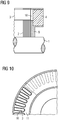
- FIG. 9 a further embodiment of the invention is shown, wherein here is the complete cross-section of the short-circuit ring 4 within the end plate 9.
- FIG. 10 shows a part of the squirrel cage of the invention FIG. 9 from another angle.
- FIG. 11 an embodiment in which the end plate 9 is reduced in the region of the connection to the shaft 1 in the material thickness, or is completely dispensed with a connection. Furthermore, it is conceivable to provide radially outwardly running and / or tangentially extending grooves on the side of the short-circuit ring 4 facing away from the rotor bars 3, so that cooling of the short-circuit ring 4 occurs during operation of the asynchronous machine.
- FIG. 12 shows a part of the squirrel cage invention of FIG. 11 from another angle.
- FIG. 13 shows an exemplary asynchronous machine with a housing 12 and a junction box 13th
Landscapes
- Engineering & Computer Science (AREA)
- Power Engineering (AREA)
- Induction Machinery (AREA)
- Windings For Motors And Generators (AREA)
Description
- Die Erfindung betrifft eine Asynchronmaschine mit einem Ständer und einem Käfigläufer, wobei der Käfigläufer eine Welle und ein Blechpaket aufweist und sich in dem Blechpaket Läuferstäbe befinden, welche an beiden Enden des Blechpakets durch die Durchbrüche je einer Endplatte geführt sind und mit einem Kurzschlussring abgeschlossen sind, welcher die Enden der Läuferstäbe einer Seite des Käfigläufers elektrisch leitend verbindet.
- Elektrische Maschinen werden in sehr vielen technischen Bereichen verwendet. Bei elektrischen Maschinen ist zu unterscheiden zwischen Gleichstrommaschinen, Wechselstrommaschinen und Drehstrommaschinen. Drehstrommaschinen können unterteilt werden in Drehstrom-Synchronmaschinen und Drehstrom-Asynchronmaschinen.
- Alle diese elektrischen Maschinen enthalten u. a. einen ruhenden Ständer und einen drehbar gelagerten Läufer. Der Läufer ist je nach Bauform mit einem Wicklungssystem bestückt. Dieses Wicklungssystem kann aus einer oder mehreren Drahtwicklungen oder Stabwicklungen bestehen. Aus Drahtwicklungen oder auch Stabwicklungen können auch Käfigwicklungen konstruiert werden. Im Fall von Stäben und Kurzschlusswicklungen bei Asynchronmotoren ergeben sich Käfigläufer. In diesem Fall enthält das Blechpaket des Läufers Läuferstäbe, welche an ihren Enden mittels Kurzschlussringen leitend miteinander verbunden werden.
- Es ist bekannt, dass der Übergangsbereich der Läuferstäbe zu den Kurzschlussringen bei Erwärmung des Läufers während des Betriebs einer Scherbeanspruchung ausgesetzt ist, so dass es zum Bruch der Verbindungsstelle kommen kann. Dies liegt vor allem an der unterschiedlichen Ausdehnung des Läuferblechpakets und der Kurzschlussringe bei Erwärmung sowie an Zentrifugalkräften während des Betriebs. In der Schrift
JP 2000-014105-A EP 1 453 180 A2 auch bekannt, die Läuferstäbe auf jeder Seite durch eine Endplatte zu führen, bevor der Kurzschlussring angeschlossen wird. - Nachteilig ist aber, dass die Gefahr eines Bruchs einer Verbindung zwischen einem Läuferstab und einem Kurschlussring zwar verringert wird, ein Bruch aber dennoch vorkommen kann. Der Erfindung liegt deshalb die Aufgabe zugrunde, eine Asynchronmaschine mit einem Käfigläufer zu schaffen, bei dem ein Bruch der Verbindung zwischen einem Läuferstab und einem Kurzschlussring vermieden wird.
- Diese Aufgabe wird erfindungsgemäß dadurch gelöst, dass jede Endplatte einen umlaufenden Vorsprung aufweist, welcher den Kurzschlussring an dessen Außenseite zumindest teilweise formschlüssig abdeckt.
- Damit wird vorteilhaft erreicht, dass jeder Kurzschlussring an seiner Außenseite von einer Endplatte gehalten und eingefasst wird, wodurch sich der Kurzschlussring bei Erwärmung während des Betriebs nicht zu stark ausdehnen kann und eine Scherbeanspruchung und ein Bruch des Übergangsbereichs der Läuferstäbe zu den Kurzschlussringen verhindert wird. Weiterhin wird der Kurzschlussring auch bei hohen Drehzahlen und hohen Zentrifugalkräften sicher an seinem Platz gehalten. Die Ausgestaltung umfasst weiterhin, dass die Läuferstäbe an ihren Enden eine Verdickung mit einem vergrößerten Stabquerschnitt aufweisen, wobei die Verdickung der Läuferstäbe in der Endplatte liegt. Damit ist der Übergangsbereich der Läuferstäbe zu den Kurzschlussringen noch besser und stabiler ausgeführt und die Gefahr eines Bruchs wird nochmals reduziert.
- Weiterhin wird der Übergang zwischen Verdickung und Kurzschlussring in Form einer Rundung mit einem Übergangsradius ausgebildet. Dies beseitigt bruchgefährdete Eckstellen, bei denen besonders große Scherbeanspruchungen auftreten.
- Um die Verdickungen besser auf dem Kreisquerschnitt anzuordnen, können diese auch leicht versetzt zu den Läuferstäben angeordnet werden. Damit wird z.B. vorteilhaft erreicht, dass eine Verdickung nicht über den Rand des Käfigläufers herausragt.
- Die Anzahl der Durchbrüche einer Endplatte kann gleich der Anzahl der Läuferstäbe sein oder auch kleiner. Im ersten Fall wird eine besonders präzise und sichere Führung der Läuferstäbe erreicht, so dass die Läuferstäbe durch die Endplatte vor Bruch geschützt werden. Im zweiten Fall werden mehrere Läuferstäbe durch eine Öffnung in der Endplatte geführt, was besonders vorteilhaft ist, wenn die Endplatte einfach und billig gefertigt werden soll.
- Eine weitere vorteilhafte Ausgestaltung ergibt sich, wenn jede Endplatte einen weiteren umlaufenden Vorsprung aufweist, welcher den Kurzschlussring an dessen Innenseite zumindest teilweise formschlüssig abdeckt. Damit ist also nicht nur die Außenseite des Kurzschlussrings durch die Endplatte abgestützt, sondern auch die Innenseite. Diese Führung dient u. a. auch dem Schutz des Kurzschlussringes vor mechanischen Beschädigungen.
- Darüber hinaus können die Übergangsstellen im Profil der Läuferstäbe und/oder der Kurzschlussringe im durch eine Endplatte eingefassten Bereich in Form einer Rundung mit einem Übergangsradius ausgebildet werden. Dies vermeidet bruchgefährdete Eckstellen und erhöht somit die Festigkeit und Zuverlässigkeit des Käfigläufers.
- Die Endplatte wird vorteilhafter Weise so ausgebildet, dass sie im Bereich der Anbindung zur Welle eine vergleichsweise geringe Materialstärke aufweist oder eine so große mittige Öffnung aufweist, so dass die Welle nicht berührt wird. Durch beide alternativen Maßnahmen wird Material eingespart und das Trägheitsmoment des Käfigläufers reduziert.
- Vorteilhafter Weise werden die Läuferstäbe und die Kurzschlussringe aus einem gut elektrisch leitenden Material wie Kupfer oder Aluminium aus einem Teil gefertigt, bzw. als ein Teil gegossen.
- Weiterhin ist denkbar, an der den Läuferstäben abgewandte Seite des Kurzschlussringes radial nach außen laufende und/oder tangential verlaufende Rillen vorzusehen, so dass eine vorteilhafte Kühlung des Kurzschlussringes besonders während des Betriebs der Asynchronmaschine eintritt.
- Die Erfindung sowie weitere vorteilhafte Ausgestaltungen der Erfindung gemäß den Merkmalen der Unteransprüche werden im folgenden anhand von schematisch dargestellten Ausführungsbeispielen in der Zeichnung näher erläutert, ohne dass dadurch eine Beschränkung der Erfindung auf dieses Ausführungsbeispiel erfolgt; es zeigen:
- FIG 1
- einen Teil eines Käfigläufers nach dem Stand der Technik;
- FIG 2
- einen Teil eines erfindungsgemäßen Käfigläufers;
- FIG 3
- einen Teil eines weiteren erfindungsgemäßen Käfigläufers;
- FIG 4
- einen Teil des erfindungsgemäßen Käfigläufers von
FIG 3 ; - FIG 5
- einen Teil eines weiteren erfindungsgemäßen Käfigläufers;
- FIG 6
- einen Teil des erfindungsgemäßen Käfigläufers von
FIG 5 ; - FIG 7
- einen Teil eines weiteren erfindungsgemäßen Käfigläufers;
- FIG 8
- einen Teil des erfindungsgemäßen Käfigläufers von
FIG 7 ; - FIG 9
- einen Teil eines weiteren erfindungsgemäßen Käfigläufers;
- FIG 10
- einen Teil des erfindungsgemäßen Käfigläufers von
FIG 9 ; - FIG 11
- einen Teil eines weiteren erfindungsgemäßen Käfigläufers;
- FIG 12
- einen Teil des erfindungsgemäßen Käfigläufers von
FIG 11 ; - FIG 13
- eine beispielhafte Asynchronmaschine.
- In
FIG 1 ist ein Teil eines Käfigläufers nach dem Stand der Technik dargestellt. Bei drehenden elektrischen Maschinen, die nach dem Induktionsprinzip arbeiten, werden die Kurzschlusswicklungen im Läufer aus elektrisch gut leitendem Material - vorzugsweise Kupfer oder Aluminium - ausgeführt. Diese Kurzschlusswicklung besteht zum einen aus einer bestimmten Anzahl von Läuferstäben 3 mit definiertem Querschnitt, die im Läuferblechpaket 2 eingebettet sind. Zum anderen befindet sich an den Stirnseiten des Blechpaketes jeweils ein Kurzschlussring 4, der alle Läuferstäbe 3 der entsprechenden Läuferseite miteinander verbindet, d.h. diese elektrisch kurzschließt. Derzeit werden Läuferwicklungen aus Aluminium i.a. im Druckgussverfahren hergestellt. - In
FIG 1 ist gezeigt, dass das Blechpaket 2 sich beim Gießen zwischen zwei stirnseitig angeordneten Druckgussformen 6 befindet, so dass sich eine Formkavität ergibt, die aus den Läuferstäben 3 im Blechpaket 2 sowie den Kurzschlussringen 4 besteht und die vollständig mit Aluminium gefüllt wird. Diese grundsätzliche Anordnung gilt auch für andere Gießwerkstoffe. Der Kurzschlussring 4 hat einen erheblich größeren Querschnitt als die einzelnen Läuferstäbe 3, wobei sich in der Darstellung nachFIG 1 ein scharfkantiger Übergang 5 zwischen diesen beiden Querschnitten ergibt. Beim Betrieb der Maschine wird diese Struktur mechanisch und thermisch beansprucht. Das Blechpaket 2 ist auf der Welle 1 angebracht. - Im Allgemeinen wird die Maschine mit veränderlichen Drehzahlen und Belastungen gefahren, so dass diese Beanspruchungen dynamisch werden. Auf den Kurzschlussring 4 wirken wegen des relativ großen Volumens vergleichsweise große Zentrifugalkräfte. Bei der Verwendung von Aluminium ist zusätzlich zu berücksichtigen, dass der Wärmausdehnungskoeffizient dieses Materials etwa doppelt so hoch wie der von Stahl, d.h. unter der belastungsbedingten Temperaturentwicklung im Läufer wächst der Kurzschlussring 4 stärker als das Blechpaket 2. Diese beiden Effekte führen zu einer radialen Verlagerung des Kurzschlussringes nach außen. Die Läuferstäbe 3 können dieser Bewegung durch die Einbettung in das Blechpaket 2 nicht ungehindert nachfolgen, was durch die Scherbeanspruchung an der Kerbstelle 5 zu unzulässig hohen Spannungen und zum Bruch der Verbindung der Läuferstäbe 3 und Kurzschlussringe 4 führen kann. Besonders bei Kurzschlusswicklungen aus Aluminium schränkt dieser Effekt den Anwendungsbereich der Läufer hinsichtlich der Betriebsbedingungen der elektrischen Maschine (Drehzahl, Belastung) stark ein
-
FIG 2 zeigt einen Teil eines erfindungsgemäßen Käfigläufers. Bei dem erfindungsgemäßen Käfigläufer wird die hohe Scherbeanspruchung an der Verbindungsstelle zwischen Läuferstäben 3 und Kurzschlussringen 4 unmittelbar unterdrückt. Die massive Endplatte 9 enthält einen beliebigen Teil des Kurzschlussring-Querschnittes und optional einen vergrößerten Stabquerschnitt 7 oder einen Übergangsradius 8 oder beides. Somit wird der Kurzschlussring 4 an der gefährdeten Übergangsstelle daran gehindert, sich radial nach außen zu bewegen und abzubrechen. - Die Endplatte 9 enthält somit einen Teil des Läuferstabes 3 und einen Teil des Kurzschlussringes 4. Mit dieser Maßnahme ist der gefährdete Übergang von einem Läuferstab 3 auf einen Kurzschlussring 4 vollständig durch höherfestes Material armiert. Der Vorteil ist, dass nur ein Bauelement verwendet werden muss und dem Gießen nachgelagerte Armierungen des Kurzschlussringes entfallen können. Dadurch wird auf einfache Weise der Betriebsbereich von gegossenen Läufern hinsichtlich Drehzahl- und Temperaturbeanspruchung erweitert.
- Alternativ wird die Läuferwicklung nicht im Gießverfahren hergestellt sondern aus Halbzeugen (Stäbe und Ringe) - vorzugsweise aus Kupfer - ausgeführt und somit höhere Beanspruchungen ermöglicht.
- In
FIG 3 zeigt einen Teil eines weiteren erfindungsgemäßen Käfigläufers. InFIG 3 enthält die Endplatte 9 für jeden Läuferstab 3 eine Öffnung 10, die nicht genau dem Querschnitt des Läuferstabes entsprechen muss und auch prinzipiell in der radialen Position anders angeordnet werden kann, so lange der daraus resultierende Querschnittsübergang sowohl fertigungstechnisch als auch von den Betriebskenndaten der elektrischen Maschine vertretbar bleibt. Außerdem enthält die Endplatte 9 den erfindungsgemäßen Anteil des Kurzschlussringes 11 in rotationssymmetrischer Form. Es ist auch möglich, mehrere Läuferstäbe 3 in einer Öffnung 10 in der Endplatte 9 zusammenzufassen.FIG 4 zeigt einen Teil des erfindungsgemäßen Käfigläufers vonFIG 3 aus einem anderen Sichtwinkel. -
FIG 5 ähneltFIG 3 , nur ist der außerhalb der Endplatte 9 liegende Teil des Kurzschlussringes 4 mit beliebigem Querschnitt gestaltet.FIG 6 zeigt einen Teil des erfindungsgemäßen Käfigläufers vonFIG 5 aus einem anderen Sichtwinkel. - Als weitere Ausgestaltung zeigt
FIG 7 eine Endplatte 9, die an einer oder mehreren möglichen Stellen Übergangsradien 8 besitzt.FIG 8 zeigt einen Teil des erfindungsgemäßen Käfigläufers vonFIG 7 aus einem anderen Sichtwinkel. - In
FIG 9 ist eine weitere erfindungsgemäße Ausführung dargestellt, wobei sich hier der vollständige Querschnitt des Kurzschlussringes 4 innerhalb der Endplatte 9 befindet.FIG 10 zeigt einen Teil des erfindungsgemäßen Käfigläufers vonFIG 9 aus einem anderen Sichtwinkel. - Als weitere Detaillierung zeigt
FIG 11 eine Ausführung, in der die Endplatte 9 im Bereich der Anbindung zur Welle 1 in der Materialstärke reduziert wird, bzw. auf eine Anbindung vollständig verzichtet wird. Weiterhin ist denkbar, an der den Läuferstäben 3 abgewandte Seite des Kurzschlussringes 4 radial nach außen laufende oder/und tangential verlaufende Rillen vorzusehen, so dass eine Kühlung des Kurzschlussringes 4 während des Betriebs der Asynchronmaschine eintritt.FIG 12 zeigt einen Teil des erfindungsgemäßen Käfigläufers vonFIG 11 aus einem anderen Sichtwinkel. -
FIG 13 zeigt eine beispielhafte Asynchronmaschine mit einem Gehäuse 12 und einem Anschlusskasten 13.
Claims (9)
- Asynchronmaschine mit einem Ständer und einem Käfigläufer, wobei der Käfigläufer eine Welle (1) und ein Blechpaket (2) aufweist und sich in dem Blechpaket Läuferstäbe (3) befinden, welche an beiden Enden des Blechpakets (2) durch die Öffnungen (10) je einer Endplatte (9) geführt sind und mit einem Kurzschlussring (4) abgeschlossen sind, welcher die Enden der Läuferstäbe (3) einer Seite des Käfigläufers elektrisch leitend verbindet, wobei jede Endplatte (9) einen Teil der Läuferstäbe (3) und einen Teil eines Kurzschlussrings (4) enthält, und wobei jede Endplatte (9) einen umlaufenden Vorsprung aufweist, welcher zumindest teilweise an der Außenseite des Kurzschlussrings (4) formschlüssig anliegt, dadurch gekennzeichnet,
dass die Endplatten (9) massiv ausgeführt sind und höherfestes Material gegenüber den Läuferstäben (3) und den Kurzschlussringen (4) aufweisen,
dass die Läuferstäbe (3) an ihren Enden eine Verdickung mit einem vergrößerten Stabquerschnitt (7) aufweisen, wobei zumindert ein Teil der Verdickung der Läuferstäbe (3) in den Öffnungen (10) der Endplatten (9) liegt und
dass der Übergang zwischen Verdickung und Kurzschlussring (4) in Form einer Rundung mit einem Übergangsradius (8) ausgebildet ist. - Asynchronmaschine nach Anspruch 1,
dadurch gekennzeichnet, dass die Anzahl der Öffnungen (10) einer Endplatte (9) gleich der Anzahl der Läuferstäbe (3) ist. - Asynchronmaschine nach Anspruch 1 oder 2,
dadurch gekennzeichnet, dass die Anzahl der Öffnungen (10) einer Endplatte (9) kleiner als die Anzahl der Läuferstäbe (3) ist, so dass mehrere Läuferstäbe (3) durch eine Öffnung (10) geführt werden. - Asynchronmaschine nach einem oder mehreren der Ansprüche 1 bis 3,
dadurch gekennzeichnet, dass jede Endplatte (9) einen weiteren umlaufenden Vorsprung aufweist, welcher zumindest teilweise an der Innenseite des Kurzschlussrings (4) formschlüssig anliegt. - Asynchronmaschine nach einem oder mehreren der Ansprüche 1 bis 4,
dadurch gekennzeichnet, dass Übergangsstellen im Profil der Läuferstäbe (3) und/oder der Kurzschlussringe (4) im durch eine Endplatte (9) eingefassten Bereich in Form einer Rundung mit einem vorgebbaren Übergangsradius (8) ausgebildet ist. - Asynchronmaschine nach einem oder mehreren der Ansprüche 1 bis 5,
dadurch gekennzeichnet, dass die Endplatte (9) im Bereich der Welle (1) eine vergleichsweise geringe Materialstärke aufweist oder eine so große mittige Öffnung aufweist, so dass sie die Welle (1) nicht berührt. - Asynchronmaschine nach einem oder mehreren der Ansprüche 1 bis 6,
dadurch gekennzeichnet, dass die Läuferstäbe (3) und die Kurzschlussringe (4) aus Kupfer oder Aluminium gefertigt sind. - Asynchronmaschine nach einem oder mehreren der Ansprüche 1 bis 7,
dadurch gekennzeichnet, dass die Läuferstäbe (3) und die Kurzschlussringe (4) als ein Stück im Druckguß gegossen sind. - Asynchronmaschine nach einem oder mehreren der Ansprüche 1 bis 8,
dadurch gekennzeichnet, dass der Kurzschlussring (4) an der den Läuferstäben (3) abgewandten Seite radial nach außen laufende und/oder tangential verlaufende Rillen aufweist, so dass eine Kühlung des Kurzschlussringes (4) besonders während des Betriebs der Asynchronmaschine eintritt.
Applications Claiming Priority (2)
| Application Number | Priority Date | Filing Date | Title |
|---|---|---|---|
| DE102005030377A DE102005030377A1 (de) | 2005-06-29 | 2005-06-29 | Asynchronmaschine |
| PCT/EP2006/063488 WO2007000413A1 (de) | 2005-06-29 | 2006-06-23 | Käfigläufer einer asynchronmaschine |
Publications (2)
| Publication Number | Publication Date |
|---|---|
| EP1915813A1 EP1915813A1 (de) | 2008-04-30 |
| EP1915813B1 true EP1915813B1 (de) | 2017-08-02 |
Family
ID=36955370
Family Applications (1)
| Application Number | Title | Priority Date | Filing Date |
|---|---|---|---|
| EP06777433.1A Active EP1915813B1 (de) | 2005-06-29 | 2006-06-23 | Käfigläufer einer asynchronmaschine |
Country Status (7)
| Country | Link |
|---|---|
| US (1) | US7919895B2 (de) |
| EP (1) | EP1915813B1 (de) |
| CN (1) | CN101213728B (de) |
| BR (1) | BRPI0612808B1 (de) |
| DE (1) | DE102005030377A1 (de) |
| RU (1) | RU2386201C2 (de) |
| WO (1) | WO2007000413A1 (de) |
Families Citing this family (27)
| Publication number | Priority date | Publication date | Assignee | Title |
|---|---|---|---|---|
| US8143738B2 (en) | 2008-08-06 | 2012-03-27 | Infinite Wind Energy LLC | Hyper-surface wind generator |
| USD673667S1 (en) * | 2010-11-05 | 2013-01-01 | Baldor Electric Company | Cooling tower fan motor |
| US8466593B2 (en) * | 2011-02-24 | 2013-06-18 | GM Global Technology Operations LLC | Rotor for an induction motor and method for fabricating |
| US8910371B2 (en) | 2011-02-28 | 2014-12-16 | GM Global Technology Operations LLC | Method for fabricating an induction rotor |
| CN102185403A (zh) * | 2011-05-09 | 2011-09-14 | 镇江中船现代发电设备有限公司 | 发电机转子阻尼绕组 |
| EP2592729B1 (de) | 2011-11-09 | 2018-05-02 | Siemens Aktiengesellschaft | Läufer einer Asynchronmaschine mit Halteelement |
| US9350217B2 (en) | 2011-11-18 | 2016-05-24 | GM Global Technology Operations LLC | Rotor and method of forming same |
| US20130154430A1 (en) * | 2011-12-15 | 2013-06-20 | Andrew Dragon | Induction rotor retention structure |
| US9024501B2 (en) * | 2012-10-09 | 2015-05-05 | Siemens Industry, Inc. | Rotor apparatus and methods of improving magnetization in electric machines |
| EP2728718A1 (de) | 2012-10-30 | 2014-05-07 | Siemens Aktiengesellschaft | Käfigläufer mit deformierbarer Lagerung der Läuferstäbe |
| DE102013221795A1 (de) * | 2013-10-28 | 2015-04-30 | Robert Bosch Gmbh | Rotor mit Sicherungsringen für eine Asynchronmaschine sowie Verfahren zum Fertigen derselben |
| JP5992004B2 (ja) * | 2014-03-13 | 2016-09-14 | 三菱電機株式会社 | 誘導回転電機の回転子、及び回転子の製造方法 |
| JP6424645B2 (ja) * | 2015-01-22 | 2018-11-21 | 株式会社デンソー | 回転電機 |
| DE102015223058A1 (de) * | 2015-11-23 | 2017-05-24 | Bayerische Motoren Werke Aktiengesellschaft | Käfigläufer und Verfahren für dessen Herstellung |
| JP6189001B1 (ja) * | 2016-09-21 | 2017-08-30 | 三菱電機株式会社 | 誘導電動機の回転子及び誘導電動機 |
| DE102016011758A1 (de) * | 2016-09-30 | 2018-04-05 | Wieland-Werke Ag | Verfahren zur Herstellung eines Kurzschlussrings |
| JP6745212B2 (ja) * | 2016-12-28 | 2020-08-26 | 東芝産業機器システム株式会社 | 回転子およびリラクタンス回転電機 |
| US20190229672A1 (en) * | 2018-01-19 | 2019-07-25 | General Electric Company | Systems and methods for acquiring measurements of rotor temperature of electric machines |
| DE102018104653A1 (de) * | 2018-03-01 | 2019-09-05 | Thyssenkrupp Ag | Rotor, Asynchronmaschine und Verwendung einer Druckscheibe |
| PL232572B1 (pl) * | 2018-06-22 | 2019-06-28 | Instytut Napedow I Masz Elektrycznych Komel | Klatka głębokożłobkowego wirnika silnika indukcyjnego |
| FR3088150B1 (fr) | 2018-11-06 | 2022-02-18 | Ge Energy Power Conversion Technology Ltd | Rotor a cage d'ecureuil et machine electrique asynchrone associee |
| DE102019211467A1 (de) * | 2019-07-31 | 2021-02-04 | Zf Friedrichshafen Ag | Druckgussrotor einer elektrischen Maschine |
| EP3883102A1 (de) * | 2020-03-18 | 2021-09-22 | Siemens Aktiengesellschaft | Rotor einer dynamoelektrischen maschine, dynamoelektrische maschine mit derartigem rotor und herstellungsverfahren eines derartigen rotors |
| EP3913778A1 (de) * | 2020-05-20 | 2021-11-24 | Siemens Aktiengesellschaft | Rotor mit kurzschlusskäfig |
| PL240076B1 (pl) * | 2021-04-26 | 2022-02-14 | Siec Badawcza Lukasiewicz Instytut Napedow I Masz Elektrycznych Komel | Uzwojenie klatkowe wirnika silnika indukcyjnego |
| US12567787B2 (en) * | 2023-06-29 | 2026-03-03 | Schaeffler Technologies AG & Co. KG | Electric motor rotor including end ring restrainer |
| WO2025115264A1 (ja) * | 2023-11-30 | 2025-06-05 | ニデック株式会社 | ロータおよび回転電機 |
Citations (4)
| Publication number | Priority date | Publication date | Assignee | Title |
|---|---|---|---|---|
| EP0786855A1 (de) * | 1995-07-13 | 1997-07-30 | Fanuc Ltd | Käfigläufer |
| US5719457A (en) * | 1995-06-14 | 1998-02-17 | Abb Daimler-Benz Transportation (Schweiz) Ag | Squirrel-cage rotor for an asynchronous machine |
| JPH10174389A (ja) * | 1996-12-12 | 1998-06-26 | Hitachi Ltd | カゴ型回転子、及びその製造方法 |
| JPH10322990A (ja) * | 1997-05-22 | 1998-12-04 | Hitachi Ltd | かご型回転電機の回転子 |
Family Cites Families (21)
| Publication number | Priority date | Publication date | Assignee | Title |
|---|---|---|---|---|
| DE10154C (de) | G. B. STOCK in Toronto in Canada | Neuerungen an Bremsen für Eisenbahnfahrzeuge | ||
| US1508152A (en) * | 1922-05-04 | 1924-09-09 | Gen Electric | Squirrel-cage winding for alternating-current motors |
| CH232999A (de) | 1942-03-25 | 1944-06-30 | Licentia Gmbh | Verfahren zur Herstellung eines Induktionsmotors mit Käfigläufer für hohe Drehzahlen. |
| DD10154A (de) * | 1952-04-29 | 1955-08-18 | ||
| JPS51114606A (en) * | 1975-04-02 | 1976-10-08 | Hitachi Ltd | Almi-cast rotor |
| SU547928A1 (ru) | 1975-08-01 | 1977-02-25 | Институт Электродинамики Ан Украинской Сср | Ротор асинхронного двигател |
| US4158225A (en) * | 1975-08-21 | 1979-06-12 | Ronk Electrical Industries, Inc. | Rotary dynamoelectric machine having high-resistance rotor |
| SU1239788A1 (ru) * | 1983-04-07 | 1986-06-23 | Научно-исследовательский институт завода "Сибэлектротяжмаш" | Ротор асинхронного двигател с литой короткозамкнутой обмоткой |
| JPS605764A (ja) | 1983-06-22 | 1985-01-12 | Hitachi Ltd | かご形回転子 |
| CH665063A5 (de) * | 1984-11-29 | 1988-04-15 | Bbc Brown Boveri & Cie | Asynchronlaeufer. |
| SU1283900A1 (ru) * | 1985-08-16 | 1987-01-15 | Предприятие П/Я А-3724 | Ротор асинхронного двигател |
| SU1529361A1 (ru) * | 1987-11-25 | 1989-12-15 | Rogushkin Aleksandr A | Короткозамкнутый ротор асинхронного электродвигател |
| SU1552297A1 (ru) * | 1988-06-06 | 1990-03-23 | Научно-Исследовательский, Проектно-Конструкторский И Технологический Институт Завода "Сибэлектротяжмаш" | Короткозамкнутый ротор асинхронного двигател |
| JP2585711Y2 (ja) | 1991-12-13 | 1998-11-25 | 石川島播磨重工業株式会社 | 高速誘導電動機の回転子 |
| DE4209118C2 (de) * | 1991-12-23 | 1993-12-09 | Loher Ag | Asynchronmotor |
| CN2150662Y (zh) * | 1993-01-16 | 1993-12-22 | 天津市起重电机厂 | 耐振电动机 |
| JPH08149769A (ja) * | 1994-11-21 | 1996-06-07 | Yaskawa Electric Corp | 誘導電動機のダイキャストロータ |
| RU2133072C1 (ru) * | 1998-03-06 | 1999-07-10 | Долина Владлен Иванович | Короткозамкнутый ротор в.и.долины |
| JP4028089B2 (ja) * | 1998-06-18 | 2007-12-26 | 東芝三菱電機産業システム株式会社 | かご形回転子鉄心の製造方法 |
| CN1304204A (zh) * | 1999-12-02 | 2001-07-18 | 合肥皖化电机技术开发有限责任公司 | 具有防转子导条断裂装置的鼠笼型异步电机 |
| DE10309161A1 (de) * | 2003-02-28 | 2004-09-16 | Siemens Ag | Elektrische Maschine mit geblechtem Läufer |
-
2005
- 2005-06-29 DE DE102005030377A patent/DE102005030377A1/de not_active Withdrawn
-
2006
- 2006-06-23 US US11/994,020 patent/US7919895B2/en active Active
- 2006-06-23 WO PCT/EP2006/063488 patent/WO2007000413A1/de not_active Ceased
- 2006-06-23 CN CN2006800235208A patent/CN101213728B/zh active Active
- 2006-06-23 EP EP06777433.1A patent/EP1915813B1/de active Active
- 2006-06-23 BR BRPI0612808-4A patent/BRPI0612808B1/pt not_active IP Right Cessation
- 2006-06-23 RU RU2008103276/09A patent/RU2386201C2/ru active
Patent Citations (4)
| Publication number | Priority date | Publication date | Assignee | Title |
|---|---|---|---|---|
| US5719457A (en) * | 1995-06-14 | 1998-02-17 | Abb Daimler-Benz Transportation (Schweiz) Ag | Squirrel-cage rotor for an asynchronous machine |
| EP0786855A1 (de) * | 1995-07-13 | 1997-07-30 | Fanuc Ltd | Käfigläufer |
| JPH10174389A (ja) * | 1996-12-12 | 1998-06-26 | Hitachi Ltd | カゴ型回転子、及びその製造方法 |
| JPH10322990A (ja) * | 1997-05-22 | 1998-12-04 | Hitachi Ltd | かご型回転電機の回転子 |
Also Published As
| Publication number | Publication date |
|---|---|
| US7919895B2 (en) | 2011-04-05 |
| RU2008103276A (ru) | 2009-08-10 |
| CN101213728A (zh) | 2008-07-02 |
| BRPI0612808B1 (pt) | 2018-03-20 |
| CN101213728B (zh) | 2010-10-13 |
| WO2007000413A1 (de) | 2007-01-04 |
| US20080185934A1 (en) | 2008-08-07 |
| RU2386201C2 (ru) | 2010-04-10 |
| BRPI0612808A2 (pt) | 2010-11-30 |
| DE102005030377A1 (de) | 2007-01-11 |
| EP1915813A1 (de) | 2008-04-30 |
Similar Documents
| Publication | Publication Date | Title |
|---|---|---|
| DE102005030377A1 (de) | Asynchronmaschine | |
| EP2951909B1 (de) | Rotor, reluktanzmaschine und herstellungsverfahren für den rotor | |
| EP2688183B1 (de) | Gießtechnisch hergestellte elektrische Spule | |
| EP2606560B1 (de) | Stab eines käfigläufers | |
| EP2965408B1 (de) | Reluktanzrotor mit anlaufhilfe | |
| EP3248271B1 (de) | Rotor einer asynchronmaschine | |
| EP3134960B1 (de) | Elektrische maschine | |
| EP2849320A2 (de) | Käfigläuferrotor für eine Asynchronmaschine mit angegossener Stabilisierung der Kurzschlussringe | |
| WO2016146271A1 (de) | Rotor einer synchronen reluktanzmaschine | |
| EP2957024B1 (de) | Fliehkraftabstützung eines kurzschlussrings bei induktionsmaschinen | |
| EP3469694A1 (de) | Kurzschlussläufer insbesondere für hochdrehzahlen | |
| EP2885858B1 (de) | Käfigrotor für eine elektrische maschine | |
| WO2016055186A1 (de) | Käfigläufer für eine elektrische asynchronmaschine mit einen kurzschlussring stabilisierender stützscheibe | |
| AT509042A2 (de) | Rotor für asynchronmaschinen | |
| DE102009014460A1 (de) | Käfigläufer aus zwei Teilpaketen | |
| WO2017129407A1 (de) | Rotor, elektrische maschine und verfahren zur herstellung eines rotors | |
| EP3145059A1 (de) | Käfigläufer | |
| WO2007000424A1 (de) | Käfigläufer einer induktionsmaschine | |
| DE102015202004A1 (de) | Käfigläuferrotor mit stabilem Kurzschlussring für eine elektrische Asynchronmaschine sowie Verfahren zum Fertigen desselben | |
| EP2979351B1 (de) | Läufer für einen elektromotor | |
| EP3706288A1 (de) | Blechpaket für eine elektrische maschine | |
| EP1883150A2 (de) | Läufer einer elektrischen Asynchronmaschine | |
| DE102017003294A1 (de) | Rotor für einen Elektromotor | |
| EP4122086A1 (de) | Rotor mit kurzschlusskäfig | |
| AT515989B1 (de) | Kurzschlussrotor |
Legal Events
| Date | Code | Title | Description |
|---|---|---|---|
| PUAI | Public reference made under article 153(3) epc to a published international application that has entered the european phase |
Free format text: ORIGINAL CODE: 0009012 |
|
| 17P | Request for examination filed |
Effective date: 20071227 |
|
| AK | Designated contracting states |
Kind code of ref document: A1 Designated state(s): AT BE BG CH CY CZ DE DK EE ES FI FR GB GR HU IE IS IT LI LT LU LV MC NL PL PT RO SE SI SK TR |
|
| DAX | Request for extension of the european patent (deleted) | ||
| RAP1 | Party data changed (applicant data changed or rights of an application transferred) |
Owner name: SIEMENS AKTIENGESELLSCHAFT |
|
| GRAP | Despatch of communication of intention to grant a patent |
Free format text: ORIGINAL CODE: EPIDOSNIGR1 |
|
| INTG | Intention to grant announced |
Effective date: 20170203 |
|
| GRAS | Grant fee paid |
Free format text: ORIGINAL CODE: EPIDOSNIGR3 |
|
| GRAA | (expected) grant |
Free format text: ORIGINAL CODE: 0009210 |
|
| AK | Designated contracting states |
Kind code of ref document: B1 Designated state(s): AT BE BG CH CY CZ DE DK EE ES FI FR GB GR HU IE IS IT LI LT LU LV MC NL PL PT RO SE SI SK TR |
|
| REG | Reference to a national code |
Ref country code: GB Ref legal event code: FG4D Free format text: NOT ENGLISH |
|
| REG | Reference to a national code |
Ref country code: CH Ref legal event code: EP Ref country code: AT Ref legal event code: REF Ref document number: 915469 Country of ref document: AT Kind code of ref document: T Effective date: 20170815 |
|
| REG | Reference to a national code |
Ref country code: IE Ref legal event code: FG4D Free format text: LANGUAGE OF EP DOCUMENT: GERMAN |
|
| RAP2 | Party data changed (patent owner data changed or rights of a patent transferred) |
Owner name: SIEMENS AKTIENGESELLSCHAFT |
|
| REG | Reference to a national code |
Ref country code: DE Ref legal event code: R096 Ref document number: 502006015610 Country of ref document: DE |
|
| REG | Reference to a national code |
Ref country code: CH Ref legal event code: NV Representative=s name: SIEMENS SCHWEIZ AG, CH Ref country code: CH Ref legal event code: PCOW |
|
| REG | Reference to a national code |
Ref country code: NL Ref legal event code: MP Effective date: 20170802 |
|
| REG | Reference to a national code |
Ref country code: LT Ref legal event code: MG4D |
|
| PG25 | Lapsed in a contracting state [announced via postgrant information from national office to epo] |
Ref country code: NL Free format text: LAPSE BECAUSE OF FAILURE TO SUBMIT A TRANSLATION OF THE DESCRIPTION OR TO PAY THE FEE WITHIN THE PRESCRIBED TIME-LIMIT Effective date: 20170802 Ref country code: LT Free format text: LAPSE BECAUSE OF FAILURE TO SUBMIT A TRANSLATION OF THE DESCRIPTION OR TO PAY THE FEE WITHIN THE PRESCRIBED TIME-LIMIT Effective date: 20170802 Ref country code: SE Free format text: LAPSE BECAUSE OF FAILURE TO SUBMIT A TRANSLATION OF THE DESCRIPTION OR TO PAY THE FEE WITHIN THE PRESCRIBED TIME-LIMIT Effective date: 20170802 |
|
| PG25 | Lapsed in a contracting state [announced via postgrant information from national office to epo] |
Ref country code: IS Free format text: LAPSE BECAUSE OF FAILURE TO SUBMIT A TRANSLATION OF THE DESCRIPTION OR TO PAY THE FEE WITHIN THE PRESCRIBED TIME-LIMIT Effective date: 20171202 Ref country code: PL Free format text: LAPSE BECAUSE OF FAILURE TO SUBMIT A TRANSLATION OF THE DESCRIPTION OR TO PAY THE FEE WITHIN THE PRESCRIBED TIME-LIMIT Effective date: 20170802 Ref country code: BG Free format text: LAPSE BECAUSE OF FAILURE TO SUBMIT A TRANSLATION OF THE DESCRIPTION OR TO PAY THE FEE WITHIN THE PRESCRIBED TIME-LIMIT Effective date: 20171102 Ref country code: GR Free format text: LAPSE BECAUSE OF FAILURE TO SUBMIT A TRANSLATION OF THE DESCRIPTION OR TO PAY THE FEE WITHIN THE PRESCRIBED TIME-LIMIT Effective date: 20171103 Ref country code: LV Free format text: LAPSE BECAUSE OF FAILURE TO SUBMIT A TRANSLATION OF THE DESCRIPTION OR TO PAY THE FEE WITHIN THE PRESCRIBED TIME-LIMIT Effective date: 20170802 Ref country code: ES Free format text: LAPSE BECAUSE OF FAILURE TO SUBMIT A TRANSLATION OF THE DESCRIPTION OR TO PAY THE FEE WITHIN THE PRESCRIBED TIME-LIMIT Effective date: 20170802 |
|
| PG25 | Lapsed in a contracting state [announced via postgrant information from national office to epo] |
Ref country code: DK Free format text: LAPSE BECAUSE OF FAILURE TO SUBMIT A TRANSLATION OF THE DESCRIPTION OR TO PAY THE FEE WITHIN THE PRESCRIBED TIME-LIMIT Effective date: 20170802 Ref country code: RO Free format text: LAPSE BECAUSE OF FAILURE TO SUBMIT A TRANSLATION OF THE DESCRIPTION OR TO PAY THE FEE WITHIN THE PRESCRIBED TIME-LIMIT Effective date: 20170802 Ref country code: CZ Free format text: LAPSE BECAUSE OF FAILURE TO SUBMIT A TRANSLATION OF THE DESCRIPTION OR TO PAY THE FEE WITHIN THE PRESCRIBED TIME-LIMIT Effective date: 20170802 |
|
| REG | Reference to a national code |
Ref country code: DE Ref legal event code: R097 Ref document number: 502006015610 Country of ref document: DE |
|
| PG25 | Lapsed in a contracting state [announced via postgrant information from national office to epo] |
Ref country code: SK Free format text: LAPSE BECAUSE OF FAILURE TO SUBMIT A TRANSLATION OF THE DESCRIPTION OR TO PAY THE FEE WITHIN THE PRESCRIBED TIME-LIMIT Effective date: 20170802 Ref country code: EE Free format text: LAPSE BECAUSE OF FAILURE TO SUBMIT A TRANSLATION OF THE DESCRIPTION OR TO PAY THE FEE WITHIN THE PRESCRIBED TIME-LIMIT Effective date: 20170802 |
|
| PLBE | No opposition filed within time limit |
Free format text: ORIGINAL CODE: 0009261 |
|
| STAA | Information on the status of an ep patent application or granted ep patent |
Free format text: STATUS: NO OPPOSITION FILED WITHIN TIME LIMIT |
|
| REG | Reference to a national code |
Ref country code: FR Ref legal event code: PLFP Year of fee payment: 13 |
|
| 26N | No opposition filed |
Effective date: 20180503 |
|
| PG25 | Lapsed in a contracting state [announced via postgrant information from national office to epo] |
Ref country code: SI Free format text: LAPSE BECAUSE OF FAILURE TO SUBMIT A TRANSLATION OF THE DESCRIPTION OR TO PAY THE FEE WITHIN THE PRESCRIBED TIME-LIMIT Effective date: 20170802 |
|
| REG | Reference to a national code |
Ref country code: CH Ref legal event code: PL |
|
| REG | Reference to a national code |
Ref country code: BE Ref legal event code: MM Effective date: 20180630 |
|
| REG | Reference to a national code |
Ref country code: IE Ref legal event code: MM4A |
|
| PG25 | Lapsed in a contracting state [announced via postgrant information from national office to epo] |
Ref country code: LU Free format text: LAPSE BECAUSE OF NON-PAYMENT OF DUE FEES Effective date: 20180623 Ref country code: MC Free format text: LAPSE BECAUSE OF FAILURE TO SUBMIT A TRANSLATION OF THE DESCRIPTION OR TO PAY THE FEE WITHIN THE PRESCRIBED TIME-LIMIT Effective date: 20170802 |
|
| PG25 | Lapsed in a contracting state [announced via postgrant information from national office to epo] |
Ref country code: CH Free format text: LAPSE BECAUSE OF NON-PAYMENT OF DUE FEES Effective date: 20180630 Ref country code: LI Free format text: LAPSE BECAUSE OF NON-PAYMENT OF DUE FEES Effective date: 20180630 Ref country code: IE Free format text: LAPSE BECAUSE OF NON-PAYMENT OF DUE FEES Effective date: 20180623 |
|
| PG25 | Lapsed in a contracting state [announced via postgrant information from national office to epo] |
Ref country code: BE Free format text: LAPSE BECAUSE OF NON-PAYMENT OF DUE FEES Effective date: 20180630 |
|
| REG | Reference to a national code |
Ref country code: AT Ref legal event code: MM01 Ref document number: 915469 Country of ref document: AT Kind code of ref document: T Effective date: 20180623 |
|
| PGFP | Annual fee paid to national office [announced via postgrant information from national office to epo] |
Ref country code: FR Payment date: 20190619 Year of fee payment: 14 |
|
| PGFP | Annual fee paid to national office [announced via postgrant information from national office to epo] |
Ref country code: GB Payment date: 20190610 Year of fee payment: 14 |
|
| PG25 | Lapsed in a contracting state [announced via postgrant information from national office to epo] |
Ref country code: AT Free format text: LAPSE BECAUSE OF NON-PAYMENT OF DUE FEES Effective date: 20180623 |
|
| PG25 | Lapsed in a contracting state [announced via postgrant information from national office to epo] |
Ref country code: TR Free format text: LAPSE BECAUSE OF FAILURE TO SUBMIT A TRANSLATION OF THE DESCRIPTION OR TO PAY THE FEE WITHIN THE PRESCRIBED TIME-LIMIT Effective date: 20170802 |
|
| PG25 | Lapsed in a contracting state [announced via postgrant information from national office to epo] |
Ref country code: PT Free format text: LAPSE BECAUSE OF FAILURE TO SUBMIT A TRANSLATION OF THE DESCRIPTION OR TO PAY THE FEE WITHIN THE PRESCRIBED TIME-LIMIT Effective date: 20170802 Ref country code: HU Free format text: LAPSE BECAUSE OF FAILURE TO SUBMIT A TRANSLATION OF THE DESCRIPTION OR TO PAY THE FEE WITHIN THE PRESCRIBED TIME-LIMIT; INVALID AB INITIO Effective date: 20060623 |
|
| PG25 | Lapsed in a contracting state [announced via postgrant information from national office to epo] |
Ref country code: CY Free format text: LAPSE BECAUSE OF FAILURE TO SUBMIT A TRANSLATION OF THE DESCRIPTION OR TO PAY THE FEE WITHIN THE PRESCRIBED TIME-LIMIT Effective date: 20170802 |
|
| GBPC | Gb: european patent ceased through non-payment of renewal fee |
Effective date: 20200623 |
|
| PG25 | Lapsed in a contracting state [announced via postgrant information from national office to epo] |
Ref country code: GB Free format text: LAPSE BECAUSE OF NON-PAYMENT OF DUE FEES Effective date: 20200623 Ref country code: FR Free format text: LAPSE BECAUSE OF NON-PAYMENT OF DUE FEES Effective date: 20200630 |
|
| REG | Reference to a national code |
Ref country code: FI Ref legal event code: PCE Owner name: INNOMOTICS GMBH |
|
| PGFP | Annual fee paid to national office [announced via postgrant information from national office to epo] |
Ref country code: FI Payment date: 20250627 Year of fee payment: 20 |
|
| PGFP | Annual fee paid to national office [announced via postgrant information from national office to epo] |
Ref country code: DE Payment date: 20250625 Year of fee payment: 20 |
|
| REG | Reference to a national code |
Ref country code: DE Ref legal event code: R081 Ref document number: 502006015610 Country of ref document: DE Owner name: INNOMOTICS GMBH, DE Free format text: FORMER OWNER: SIEMENS AKTIENGESELLSCHAFT, 80333 MUENCHEN, DE |
|
| PGFP | Annual fee paid to national office [announced via postgrant information from national office to epo] |
Ref country code: IT Payment date: 20250624 Year of fee payment: 20 |