EP1914136B1 - Feststellbremse mit Sicherheitsvorrichtung, im Besonderen für einen Ackerschlepper - Google Patents
Feststellbremse mit Sicherheitsvorrichtung, im Besonderen für einen Ackerschlepper Download PDFInfo
- Publication number
- EP1914136B1 EP1914136B1 EP07118051A EP07118051A EP1914136B1 EP 1914136 B1 EP1914136 B1 EP 1914136B1 EP 07118051 A EP07118051 A EP 07118051A EP 07118051 A EP07118051 A EP 07118051A EP 1914136 B1 EP1914136 B1 EP 1914136B1
- Authority
- EP
- European Patent Office
- Prior art keywords
- parking brake
- solenoid valve
- pack
- wheels
- chamber
- Prior art date
- Legal status (The legal status is an assumption and is not a legal conclusion. Google has not performed a legal analysis and makes no representation as to the accuracy of the status listed.)
- Active
Links
Images




Classifications
-
- B—PERFORMING OPERATIONS; TRANSPORTING
- B60—VEHICLES IN GENERAL
- B60T—VEHICLE BRAKE CONTROL SYSTEMS OR PARTS THEREOF; BRAKE CONTROL SYSTEMS OR PARTS THEREOF, IN GENERAL; ARRANGEMENT OF BRAKING ELEMENTS ON VEHICLES IN GENERAL; PORTABLE DEVICES FOR PREVENTING UNWANTED MOVEMENT OF VEHICLES; VEHICLE MODIFICATIONS TO FACILITATE COOLING OF BRAKES
- B60T13/00—Transmitting braking action from initiating means to ultimate brake actuator with power assistance or drive; Brake systems incorporating such transmitting means, e.g. air-pressure brake systems
- B60T13/10—Transmitting braking action from initiating means to ultimate brake actuator with power assistance or drive; Brake systems incorporating such transmitting means, e.g. air-pressure brake systems with fluid assistance, drive, or release
- B60T13/12—Transmitting braking action from initiating means to ultimate brake actuator with power assistance or drive; Brake systems incorporating such transmitting means, e.g. air-pressure brake systems with fluid assistance, drive, or release the fluid being liquid
- B60T13/22—Brakes applied by springs or weights and released hydraulically
Definitions
- the present invention relates to a parking brake, in particular for a farm tractor, activated mechanically by a number of Belleville washers, and released hydraulically by pressurized oil.
- the parking brake also has a safety device to prevent sudden uncontrolled engagement of the brake, when the vehicle is moving, as a result of various factors, such as blackout, turning off the engine, or simply a fall in oil pressure in the main hydraulic circuit.
- EP 1 541 438 describes a prior art parking brake device.
- the present invention may be used to particular advantage, though not exclusively, in a farm tractor, to which the following description refers purely by way of example.
- a parking brake in particular for a farm tractor, with a safety device, as claimed in the accompanying Claims.
- Number 10 in the accompanying drawings indicates as a whole a parking brake in accordance with the present invention.
- Parking brake 10 comprises, in known manner, a lever 11 (with a pin 11a) rotating about an axis of rotation (a) ( Figures 1 , 2 ).
- a shaft 12 ( Figure 1 ) is integral with lever 11, and has a longitudinal axis of substantial symmetry defined by axis of rotation (a). Shaft 12 is housed inside a sleeve 13 fitted with bushings 14 ( Figure 2 ). As shown in Figure 1 , sleeve 13 is formed in one piece with a monobloc supporting structure 15 having bolts 16 for fixing parking brake 10 to the rear transmission housing (not shown) of the tractor.
- monobloc supporting structure 15 comprises a first plate 15a substantially perpendicular to axis (a); a second plate 15b substantially perpendicular to first plate 15a and supporting sleeve 13; and a third plate 15c, also perpendicular to plate 15a and therefore parallel to plate 15b.
- the distal end of shaft 12 has a cam member 17, which acts on a pack of movable sectors 18 interposed between plates 15b and 15c ( Figure 1 ).
- the pack of movable sectors 18 acts, in known manner by means of mechanical members not shown, on the pinion of the rear wheels to exert the desired braking force on the rear wheels.
- the operator can therefore activate parking brake 10 by rotating lever 11 ( Figure 2 ) (e.g. by exerting pull on a Bowden cable (not shown) fixed at one end to pin 11a; see below) in the direction indicated by arrow FR1 ( Figure 1 ) to grip the pack of movable sectors 18 and so exert braking force on the pinion of the rear wheels (not shown).
- Lever 11 can be rotated, and therefore braking force exerted on the pinion, either by means of said Bowden cable (not shown) fixed at one end to pin 11a, or by means of a device as described below.
- lever 11 is also integral with a connecting rod 19 also hinged about axis (a).
- the distal end of connecting rod 19 has an articulated joint 20 to which is hinged a fork 20a having a longitudinal axis (b) of substantial symmetry.
- fork 20a has a threaded hole 21.
- a push rod 22 is also provided, which comprises a rod 22a (also of axis (b) of substantial symmetry); a head 22b; and a bellows fastener 22c roughly halfway along rod 22a and perpendicular to axis (b).
- Rod 22a is screwed partly inside threaded hole 21.
- Hydraulic cylinder assembly 23 comprises a cylinder 24 defining a chamber 24a. Chamber 24a houses a piston 25 stressed by a pack of Belleville washers 26 (see below).
- piston 25 substantially comprises a central body 25a; a top portion 25b, in turn having a cavity 25c; and a guide and sealing member 25d.
- the bottom portion of central body 25a slides inside a cylindrical guide 27 projecting inside chamber 24a; and the pack of Belleville washers 26 is located between one end 27a of cylindrical guide 27 and guide member 25d.
- head 22b and part of rod 22a are housed inside cavity 25c. More specifically, head 22b rests on the bottom of cavity 25c.
- Push rod 22 acts as an intermediate transmission member between fork 20a and piston 25, and is detached from piston 25.
- a first end of a bellows 29 is fitted to bellows fastener 22c; and a second end of bellows 29 is secured to the top of cylinder 24.
- portion 24a* of chamber 24a contains pressurized oil, meaning that the device is in the parking position.
- Belleville washers 26 are therefore partly compressed between end 27a and guide member 25d, and transmit their force to piston 25 in the direction of arrow FR2.
- lever 11 rotates in the direction of arrow FR1, thus producing all the related braking phenomena on movable sectors 18, as described previously relative to manual operation.
- hydraulic cylinder assembly 23 has a pressurized-oil inlet 30 connected to a pressurized-oil distribution circuit CIR ( Figure 4 ).
- Hydraulic cylinder assembly 23 also has a valve assembly 40 comprising a first solenoid valve 41 (housed in a respective seat 41a; Figure 2 ), and a second solenoid valve 42 (housed in a respective seat 42a; Figure 2 ) connected to each other hydraulically by a conduit 43 ( Figure 2 ).
- seat 42a is connected to an inlet 44 of a hand pump (not shown) by a conduit 45.
- inlet 44 has an opening 46 in portion 24a* of chamber 24a.
- Oil directly from hydraulic circuit CIR (through inlet 30, conduits 43, 45, inlet 44, and opening 46) or oil pumped by the hand pump (directly through inlet 44 and opening 46) therefore flows in or out through opening 46.
- a drain conduit 47 extends from seat 41a and, as will be seen below, is open or closed depending on the position of the slides of solenoid valve 41.
- a Bowden cable (not shown) is connected to the bottom end 25a* of central body 25a to release the brake mechanically.
- parking brake 10 can be activated either manually, acting directly on lever 11, or automatically, by releasing the pressure inside cylinder 24 to push piston 25 upwards by means of the pack of Belleville washers 26.
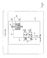
- FIG. 4 shows a hydraulic arrangement 100 of parking brake 10 according to the present invention. Many of the details in hydraulic arrangement 100 have already been described. Hydraulic arrangement 100 comprises circuit CIR for distributing pressurized oil to a number of user devices (not shown) on the tractor.
- inlet 30 shown schematically in Figure 4 as a segment
- first solenoid valve 41 connected hydraulically to second solenoid valve 42 by conduit 43
- conduits 45, 46 between second solenoid valve 42 and hydraulic cylinder assembly 23.
- Hydraulic arrangement 100 in Figure 4 also comprises drain conduit 47, inside cylinder 24, for draining oil into the transmission housing which acts as a tank (not shown).
- the tractor is obviously braked by simply gripping movable sectors 18 by draining the oil along drain conduit 47, as shown in Figure 6 (considering solenoid valve 41 only).
- solenoid valve 41 is deenergized and returns to the drain configuration in Figure 6 .
- the parking brake ( Figure 6 ) is activated (in totally uncontrolled manner), thus resulting in sharp braking of the tractor (which is obviously to be avoided at all cost).
- a second safety solenoid valve 42 (with slides 42b, 42c) has therefore been provided between first solenoid valve 41 and hydraulic cylinder assembly 23.
- solenoid valve 42 is energized ("ON” position), while solenoid valve 41 is deenergized (“OFF” position), so that slide 41b is aligned with slide 42c ( Figure 6 ).
- a blackout causes the system to switch from the Figure 5 configuration to the Figure 4 configuration as shown in Figure 7 .
- the one-way valve in slide 42b of solenoid valve 42 keeps the drain closed, thus keeping the chamber pressurized and the parking brake off.
- solenoid valve 42 By adding a safety solenoid valve 42 to solenoid valve assembly 40, a system is achieved which is intrinsically safer in the event of a blackout or a fall in hydraulic system pressure.
Landscapes
- Engineering & Computer Science (AREA)
- Transportation (AREA)
- Mechanical Engineering (AREA)
- Braking Arrangements (AREA)
- Braking Elements And Transmission Devices (AREA)
- Harvester Elements (AREA)
- Braking Systems And Boosters (AREA)
Claims (5)
- Feststellbremse (10) für ein Motorfahrzeug, insbesondere für Ackerschlepper, mit einer elektromechanischen und hydraulischen Vorrichtung (11, 19, 23, 40) zum Einspannen eines Stapels von beweglichen Sektoren (18), die mechanisch mit den Rädern verbunden sind, um auf Befehl die gewünschte Bremskraft auf die Räder auszuüben; und
dadurch gekennzeichnet, dass die Feststellbremse (10) eine Ölströmungs-Regelventil-Baugruppe (40) umfasst, die einen Teil der elektromechanischen und hydraulischen Vorrichtung (11, 19, 23, 40) bildet und ihrerseits ein erstes Steuer-Magnetventil (41) und ein zweites Sicherheits-Magnetventil (42) in Serie miteinander umfasst. - Feststellbremse (10) nach Anspruch 1, bei der die elektromechanische und hydraulische Vorrichtung (11, 19, 23, 40) weiterhin einen Hydraulikkreis (CIR) umfasst, der eine Hydraulikzylinder-Baugruppe (23) speist, die ihrerseits einen Zylinder (24) umfasst, der eine Kammer (24a) bildet, die einen Kolben (25) aufnimmt, der durch einen Stapel von Tellerfedern (26) vorgespannt ist; wobei der Zylinder (24) betreibbar ist, um einen Stapel von beweglichen Sektoren (18) zu aktivieren oder zu deaktivieren, die mechanisch mit einem Zahnrad der Räder verbunden sind, um die gewünschte Bremskraft auf die Räder auszuüben.
- Feststellbremse (10) nach Anspruch 2, bei der beim Einstellen des Steuer-Magnetventils (41) auf eine "EIN"-Position ein Abschnitt (24a*) der Kammer (24a) mit Druck beaufschlagt wird und der Kolben (25) sich zur Freigabe des Stapels von beweglichen Sektoren (18) bewegt, um damit die Feststellbremse (10) zu deaktivieren; wobei sich das Sicherheits-Magnetventil in einer "AUS"-Position befindet.
- Feststellbremse (10) nach Anspruch 3. bei der zum Entlasten des Abschnitts (24a*) der Kammer lediglich das Sicherheits-Magnetventil (42) auf die "EIN"-Position angesteuert wird und das Steuer-Magnetventil (41) auf eine "AUS"-Stellung abgeschaltet ist.
- Feststellbremse (10) nach Anspruch 1, bei der im Fall eines unerwünschten Druckabfalls in dem Hydraulikkreis (CIR) der elektrische Strom an die Magnetventile (41, 42) abgeschaltet wird, die daher beide in der "AUS"-Stellung bleiben.
Applications Claiming Priority (1)
| Application Number | Priority Date | Filing Date | Title |
|---|---|---|---|
| IT000714A ITBO20060714A1 (it) | 2006-10-16 | 2006-10-16 | Freno di stazionamento, in particolare per un trattore agricolo, provvisto di un dispositivo di sicurezza |
Publications (2)
| Publication Number | Publication Date |
|---|---|
| EP1914136A1 EP1914136A1 (de) | 2008-04-23 |
| EP1914136B1 true EP1914136B1 (de) | 2009-05-06 |
Family
ID=38868275
Family Applications (1)
| Application Number | Title | Priority Date | Filing Date |
|---|---|---|---|
| EP07118051A Active EP1914136B1 (de) | 2006-10-16 | 2007-10-08 | Feststellbremse mit Sicherheitsvorrichtung, im Besonderen für einen Ackerschlepper |
Country Status (5)
| Country | Link |
|---|---|
| US (1) | US7931343B2 (de) |
| EP (1) | EP1914136B1 (de) |
| AT (1) | ATE430677T1 (de) |
| DE (1) | DE602007001063D1 (de) |
| IT (1) | ITBO20060714A1 (de) |
Families Citing this family (8)
| Publication number | Priority date | Publication date | Assignee | Title |
|---|---|---|---|---|
| CN102019942B (zh) * | 2010-11-30 | 2012-10-03 | 南车洛阳机车有限公司 | 特种铁道车辆停车制动控制装置 |
| US9254828B2 (en) * | 2012-08-17 | 2016-02-09 | Edwin Bernard Simpson | Safety valve for trailer |
| DE102012107812A1 (de) * | 2012-08-24 | 2014-05-28 | Krones Ag | Vorrichtung und Verfahren zur Behandlung von Behältnissen mit einer mechanischen Bremseinrichtung |
| KR102142832B1 (ko) * | 2013-11-21 | 2020-08-10 | 현대모비스 주식회사 | 전자기계식 브레이크의 초기화 장치 및 방법 |
| US9421958B2 (en) * | 2014-06-24 | 2016-08-23 | Cnh Industrial America Llc | Braking system for a work vehicle |
| CN105270377B (zh) * | 2014-07-09 | 2018-07-13 | 现代摩比斯株式会社 | 电子机械式制动装置的初始化方法 |
| ITUB20155206A1 (it) * | 2015-10-21 | 2017-04-21 | Cnh Ind Italia Spa | Veicolo motorizzato comprendente un freno di tipo SAHR. |
| CN114670934B (zh) * | 2022-04-15 | 2023-08-25 | 山推工程机械股份有限公司 | 一种车辆控制系统及车辆 |
Family Cites Families (7)
| Publication number | Priority date | Publication date | Assignee | Title |
|---|---|---|---|---|
| US3613839A (en) * | 1968-12-31 | 1971-10-19 | Bendix Corp | Vehicle brake system |
| GB9102472D0 (en) * | 1991-02-05 | 1991-03-20 | Lucas Ind Plc | Braking system for a vehicle |
| WO1998023474A1 (en) * | 1996-11-22 | 1998-06-04 | Svendborg Brakes A/S | A hydraulic braking system |
| ITBO20030533A1 (it) * | 2003-09-15 | 2005-03-16 | Cnh Italia Spa | Freno di stazionamento per un autoveicolo, in particolare per un trattore |
| JP4164020B2 (ja) * | 2003-12-11 | 2008-10-08 | 株式会社豊田自動織機 | 車両の駐車ブレーキ装置 |
| WO2005093280A1 (ja) * | 2004-03-26 | 2005-10-06 | Honda Motor Co., Ltd. | パーキングブレーキ装置 |
| US7517026B1 (en) * | 2007-12-05 | 2009-04-14 | Deere & Company | Control circuit for trailer brakes in a by-wire brake system |
-
2006
- 2006-10-16 IT IT000714A patent/ITBO20060714A1/it unknown
-
2007
- 2007-10-08 AT AT07118051T patent/ATE430677T1/de not_active IP Right Cessation
- 2007-10-08 DE DE602007001063T patent/DE602007001063D1/de active Active
- 2007-10-08 EP EP07118051A patent/EP1914136B1/de active Active
- 2007-10-16 US US11/974,752 patent/US7931343B2/en active Active
Also Published As
| Publication number | Publication date |
|---|---|
| DE602007001063D1 (de) | 2009-06-18 |
| US20080093917A1 (en) | 2008-04-24 |
| EP1914136A1 (de) | 2008-04-23 |
| ATE430677T1 (de) | 2009-05-15 |
| ITBO20060714A1 (it) | 2008-04-17 |
| US7931343B2 (en) | 2011-04-26 |
Similar Documents
| Publication | Publication Date | Title |
|---|---|---|
| EP1914136A1 (de) | Feststellbremse mit Sicherheitsvorrichtung, im Besonderen für einen Ackerschlepper | |
| US4400039A (en) | Electro-hydraulic brake system having electric control means | |
| EP3075617B1 (de) | Kombinierte Bremsvorrichtung für Fahrzeuge | |
| US9126579B1 (en) | Vehicle drive and control system | |
| AU2019205012A1 (en) | Park brake and traction drive bypass interlock | |
| EP3156320A1 (de) | Steuerungssystem für wasserfahrzeuge | |
| WO2007128058A1 (en) | Profiled cam for lever assistance | |
| PL115210B1 (en) | Vehicle drive disengaging system | |
| DE19858472A1 (de) | Fahrzeug, insbesondere Flurförderzeug, mit einer Betriebsbremse und einer Speicherbremse | |
| EP1571060B1 (de) | Fahrzeug mit einer pneumatischen Steuerleitung für Anhängerbremsen | |
| EA012540B1 (ru) | Способ для отпускания по меньшей мере одного тормозного механизма с пружинным энергоаккумулятором, приводимого в действие средой, передающей давление, а также устройство и гидравлическая схема для осуществления способа | |
| US4875563A (en) | Shift lever activated parking brake | |
| US4093048A (en) | Vehicle steering brake and clutch control | |
| WO1992002393A1 (en) | Parking brake control valve dual actuating device | |
| EP0456097B1 (de) | Not- und Feststelllbremsvorrichtung eines Fahrzeugs | |
| US4284182A (en) | Vehicle steering brake and clutch control | |
| EP1516791B1 (de) | Feststellbremse für ein Kraftfahrzeug, insbesondere Zugfahrzeug | |
| US20240166185A1 (en) | Switchable braking system, bbw module and switching device for a switchable braking system | |
| GB2427664A (en) | Work machine with spring loaded brake used as a service brake | |
| JPH10220576A (ja) | 油圧駆動変速装置の緊急停止装置 | |
| US4987983A (en) | Dual-mode powered clutch actuator | |
| US20080035433A1 (en) | Hydraulic integrated parking brake system | |
| KR20090057642A (ko) | 자동차의 주차브레이크장치 | |
| US4299300A (en) | Vehicle steering brake and clutch control | |
| US20070210644A1 (en) | Actuation device for a brake |
Legal Events
| Date | Code | Title | Description |
|---|---|---|---|
| PUAI | Public reference made under article 153(3) epc to a published international application that has entered the european phase |
Free format text: ORIGINAL CODE: 0009012 |
|
| AK | Designated contracting states |
Kind code of ref document: A1 Designated state(s): AT BE BG CH CY CZ DE DK EE ES FI FR GB GR HU IE IS IT LI LT LU LV MC MT NL PL PT RO SE SI SK TR |
|
| AX | Request for extension of the european patent |
Extension state: AL BA HR MK RS |
|
| 17P | Request for examination filed |
Effective date: 20081023 |
|
| GRAP | Despatch of communication of intention to grant a patent |
Free format text: ORIGINAL CODE: EPIDOSNIGR1 |
|
| AKX | Designation fees paid |
Designated state(s): AT BE BG CH CY CZ DE DK EE ES FI FR GB GR HU IE IS IT LI LT LU LV MC MT NL PL PT RO SE SI SK TR |
|
| GRAS | Grant fee paid |
Free format text: ORIGINAL CODE: EPIDOSNIGR3 |
|
| GRAA | (expected) grant |
Free format text: ORIGINAL CODE: 0009210 |
|
| AK | Designated contracting states |
Kind code of ref document: B1 Designated state(s): AT BE BG CH CY CZ DE DK EE ES FI FR GB GR HU IE IS IT LI LT LU LV MC MT NL PL PT RO SE SI SK TR |
|
| REG | Reference to a national code |
Ref country code: GB Ref legal event code: FG4D |
|
| REG | Reference to a national code |
Ref country code: CH Ref legal event code: EP |
|
| REG | Reference to a national code |
Ref country code: IE Ref legal event code: FG4D |
|
| REF | Corresponds to: |
Ref document number: 602007001063 Country of ref document: DE Date of ref document: 20090618 Kind code of ref document: P |
|
| PG25 | Lapsed in a contracting state [announced via postgrant information from national office to epo] |
Ref country code: FI Free format text: LAPSE BECAUSE OF FAILURE TO SUBMIT A TRANSLATION OF THE DESCRIPTION OR TO PAY THE FEE WITHIN THE PRESCRIBED TIME-LIMIT Effective date: 20090506 Ref country code: AT Free format text: LAPSE BECAUSE OF FAILURE TO SUBMIT A TRANSLATION OF THE DESCRIPTION OR TO PAY THE FEE WITHIN THE PRESCRIBED TIME-LIMIT Effective date: 20090506 Ref country code: ES Free format text: LAPSE BECAUSE OF FAILURE TO SUBMIT A TRANSLATION OF THE DESCRIPTION OR TO PAY THE FEE WITHIN THE PRESCRIBED TIME-LIMIT Effective date: 20090817 Ref country code: PT Free format text: LAPSE BECAUSE OF FAILURE TO SUBMIT A TRANSLATION OF THE DESCRIPTION OR TO PAY THE FEE WITHIN THE PRESCRIBED TIME-LIMIT Effective date: 20090906 Ref country code: LT Free format text: LAPSE BECAUSE OF FAILURE TO SUBMIT A TRANSLATION OF THE DESCRIPTION OR TO PAY THE FEE WITHIN THE PRESCRIBED TIME-LIMIT Effective date: 20090506 |
|
| NLV1 | Nl: lapsed or annulled due to failure to fulfill the requirements of art. 29p and 29m of the patents act | ||
| PG25 | Lapsed in a contracting state [announced via postgrant information from national office to epo] |
Ref country code: SE Free format text: LAPSE BECAUSE OF FAILURE TO SUBMIT A TRANSLATION OF THE DESCRIPTION OR TO PAY THE FEE WITHIN THE PRESCRIBED TIME-LIMIT Effective date: 20090806 Ref country code: NL Free format text: LAPSE BECAUSE OF FAILURE TO SUBMIT A TRANSLATION OF THE DESCRIPTION OR TO PAY THE FEE WITHIN THE PRESCRIBED TIME-LIMIT Effective date: 20090506 Ref country code: IS Free format text: LAPSE BECAUSE OF FAILURE TO SUBMIT A TRANSLATION OF THE DESCRIPTION OR TO PAY THE FEE WITHIN THE PRESCRIBED TIME-LIMIT Effective date: 20090906 Ref country code: PL Free format text: LAPSE BECAUSE OF FAILURE TO SUBMIT A TRANSLATION OF THE DESCRIPTION OR TO PAY THE FEE WITHIN THE PRESCRIBED TIME-LIMIT Effective date: 20090506 Ref country code: SI Free format text: LAPSE BECAUSE OF FAILURE TO SUBMIT A TRANSLATION OF THE DESCRIPTION OR TO PAY THE FEE WITHIN THE PRESCRIBED TIME-LIMIT Effective date: 20090506 Ref country code: LV Free format text: LAPSE BECAUSE OF FAILURE TO SUBMIT A TRANSLATION OF THE DESCRIPTION OR TO PAY THE FEE WITHIN THE PRESCRIBED TIME-LIMIT Effective date: 20090506 |
|
| PG25 | Lapsed in a contracting state [announced via postgrant information from national office to epo] |
Ref country code: EE Free format text: LAPSE BECAUSE OF FAILURE TO SUBMIT A TRANSLATION OF THE DESCRIPTION OR TO PAY THE FEE WITHIN THE PRESCRIBED TIME-LIMIT Effective date: 20090506 Ref country code: CZ Free format text: LAPSE BECAUSE OF FAILURE TO SUBMIT A TRANSLATION OF THE DESCRIPTION OR TO PAY THE FEE WITHIN THE PRESCRIBED TIME-LIMIT Effective date: 20090506 Ref country code: DK Free format text: LAPSE BECAUSE OF FAILURE TO SUBMIT A TRANSLATION OF THE DESCRIPTION OR TO PAY THE FEE WITHIN THE PRESCRIBED TIME-LIMIT Effective date: 20090506 Ref country code: RO Free format text: LAPSE BECAUSE OF FAILURE TO SUBMIT A TRANSLATION OF THE DESCRIPTION OR TO PAY THE FEE WITHIN THE PRESCRIBED TIME-LIMIT Effective date: 20090506 |
|
| PG25 | Lapsed in a contracting state [announced via postgrant information from national office to epo] |
Ref country code: SK Free format text: LAPSE BECAUSE OF FAILURE TO SUBMIT A TRANSLATION OF THE DESCRIPTION OR TO PAY THE FEE WITHIN THE PRESCRIBED TIME-LIMIT Effective date: 20090506 Ref country code: BE Free format text: LAPSE BECAUSE OF FAILURE TO SUBMIT A TRANSLATION OF THE DESCRIPTION OR TO PAY THE FEE WITHIN THE PRESCRIBED TIME-LIMIT Effective date: 20090506 |
|
| PLBE | No opposition filed within time limit |
Free format text: ORIGINAL CODE: 0009261 |
|
| STAA | Information on the status of an ep patent application or granted ep patent |
Free format text: STATUS: NO OPPOSITION FILED WITHIN TIME LIMIT |
|
| PG25 | Lapsed in a contracting state [announced via postgrant information from national office to epo] |
Ref country code: BG Free format text: LAPSE BECAUSE OF FAILURE TO SUBMIT A TRANSLATION OF THE DESCRIPTION OR TO PAY THE FEE WITHIN THE PRESCRIBED TIME-LIMIT Effective date: 20090806 |
|
| 26N | No opposition filed |
Effective date: 20100209 |
|
| PG25 | Lapsed in a contracting state [announced via postgrant information from national office to epo] |
Ref country code: MC Free format text: LAPSE BECAUSE OF NON-PAYMENT OF DUE FEES Effective date: 20091031 |
|
| REG | Reference to a national code |
Ref country code: IE Ref legal event code: MM4A |
|
| PG25 | Lapsed in a contracting state [announced via postgrant information from national office to epo] |
Ref country code: GR Free format text: LAPSE BECAUSE OF FAILURE TO SUBMIT A TRANSLATION OF THE DESCRIPTION OR TO PAY THE FEE WITHIN THE PRESCRIBED TIME-LIMIT Effective date: 20090807 Ref country code: IE Free format text: LAPSE BECAUSE OF NON-PAYMENT OF DUE FEES Effective date: 20091008 |
|
| PG25 | Lapsed in a contracting state [announced via postgrant information from national office to epo] |
Ref country code: MT Free format text: LAPSE BECAUSE OF FAILURE TO SUBMIT A TRANSLATION OF THE DESCRIPTION OR TO PAY THE FEE WITHIN THE PRESCRIBED TIME-LIMIT Effective date: 20090506 Ref country code: LU Free format text: LAPSE BECAUSE OF NON-PAYMENT OF DUE FEES Effective date: 20091008 |
|
| PG25 | Lapsed in a contracting state [announced via postgrant information from national office to epo] |
Ref country code: HU Free format text: LAPSE BECAUSE OF FAILURE TO SUBMIT A TRANSLATION OF THE DESCRIPTION OR TO PAY THE FEE WITHIN THE PRESCRIBED TIME-LIMIT Effective date: 20091107 |
|
| PG25 | Lapsed in a contracting state [announced via postgrant information from national office to epo] |
Ref country code: TR Free format text: LAPSE BECAUSE OF FAILURE TO SUBMIT A TRANSLATION OF THE DESCRIPTION OR TO PAY THE FEE WITHIN THE PRESCRIBED TIME-LIMIT Effective date: 20090506 |
|
| PG25 | Lapsed in a contracting state [announced via postgrant information from national office to epo] |
Ref country code: CY Free format text: LAPSE BECAUSE OF FAILURE TO SUBMIT A TRANSLATION OF THE DESCRIPTION OR TO PAY THE FEE WITHIN THE PRESCRIBED TIME-LIMIT Effective date: 20090506 |
|
| PG25 | Lapsed in a contracting state [announced via postgrant information from national office to epo] |
Ref country code: IT Free format text: LAPSE BECAUSE OF NON-PAYMENT OF DUE FEES Effective date: 20101008 |
|
| REG | Reference to a national code |
Ref country code: CH Ref legal event code: PL |
|
| PG25 | Lapsed in a contracting state [announced via postgrant information from national office to epo] |
Ref country code: CH Free format text: LAPSE BECAUSE OF NON-PAYMENT OF DUE FEES Effective date: 20111031 Ref country code: LI Free format text: LAPSE BECAUSE OF NON-PAYMENT OF DUE FEES Effective date: 20111031 |
|
| REG | Reference to a national code |
Ref country code: DE Ref legal event code: R082 Ref document number: 602007001063 Country of ref document: DE Representative=s name: PATENTANWAELTE WALLACH, KOCH & PARTNER, DE |
|
| REG | Reference to a national code |
Ref country code: DE Ref legal event code: R082 Ref document number: 602007001063 Country of ref document: DE Representative=s name: PATENTANWAELTE WALLACH, KOCH & PARTNER, DE Effective date: 20140623 Ref country code: DE Ref legal event code: R081 Ref document number: 602007001063 Country of ref document: DE Owner name: CNH INDUSTRIAL ITALIA S.P.A., IT Free format text: FORMER OWNER: CNH ITALIA S.P.A., MODENA, IT Effective date: 20140623 Ref country code: DE Ref legal event code: R082 Ref document number: 602007001063 Country of ref document: DE Representative=s name: PATENTANWAELTE WALLACH, KOCH, DR. HAIBACH, FEL, DE Effective date: 20140623 |
|
| REG | Reference to a national code |
Ref country code: FR Ref legal event code: CD Owner name: CNH INDUSTRIAL ITALIA S.P.A. Effective date: 20150313 |
|
| REG | Reference to a national code |
Ref country code: FR Ref legal event code: PLFP Year of fee payment: 9 |
|
| REG | Reference to a national code |
Ref country code: FR Ref legal event code: PLFP Year of fee payment: 10 |
|
| REG | Reference to a national code |
Ref country code: FR Ref legal event code: PLFP Year of fee payment: 11 |
|
| REG | Reference to a national code |
Ref country code: FR Ref legal event code: PLFP Year of fee payment: 12 |
|
| PGFP | Annual fee paid to national office [announced via postgrant information from national office to epo] |
Ref country code: GB Payment date: 20191025 Year of fee payment: 13 |
|
| REG | Reference to a national code |
Ref country code: DE Ref legal event code: R082 Ref document number: 602007001063 Country of ref document: DE Representative=s name: MEISSNER BOLTE PATENTANWAELTE RECHTSANWAELTE P, DE |
|
| REG | Reference to a national code |
Ref country code: DE Ref legal event code: R084 Ref document number: 602007001063 Country of ref document: DE |
|
| GBPC | Gb: european patent ceased through non-payment of renewal fee |
Effective date: 20201008 |
|
| PG25 | Lapsed in a contracting state [announced via postgrant information from national office to epo] |
Ref country code: GB Free format text: LAPSE BECAUSE OF NON-PAYMENT OF DUE FEES Effective date: 20201008 |
|
| PGFP | Annual fee paid to national office [announced via postgrant information from national office to epo] |
Ref country code: DE Payment date: 20251028 Year of fee payment: 19 |
|
| PGFP | Annual fee paid to national office [announced via postgrant information from national office to epo] |
Ref country code: IT Payment date: 20251024 Year of fee payment: 19 |
|
| PGFP | Annual fee paid to national office [announced via postgrant information from national office to epo] |
Ref country code: FR Payment date: 20251027 Year of fee payment: 19 |