EP0456097B1 - Not- und Feststelllbremsvorrichtung eines Fahrzeugs - Google Patents
Not- und Feststelllbremsvorrichtung eines Fahrzeugs Download PDFInfo
- Publication number
- EP0456097B1 EP0456097B1 EP91107045A EP91107045A EP0456097B1 EP 0456097 B1 EP0456097 B1 EP 0456097B1 EP 91107045 A EP91107045 A EP 91107045A EP 91107045 A EP91107045 A EP 91107045A EP 0456097 B1 EP0456097 B1 EP 0456097B1
- Authority
- EP
- European Patent Office
- Prior art keywords
- lever
- vehicle
- braking
- pump
- stirrup
- Prior art date
- Legal status (The legal status is an assumption and is not a legal conclusion. Google has not performed a legal analysis and makes no representation as to the accuracy of the status listed.)
- Expired - Lifetime
Links
- 238000007789 sealing Methods 0.000 description 3
- 235000013290 Sagittaria latifolia Nutrition 0.000 description 1
- 235000015246 common arrowhead Nutrition 0.000 description 1
- 230000006835 compression Effects 0.000 description 1
- 238000007906 compression Methods 0.000 description 1
Images


Classifications
-
- B—PERFORMING OPERATIONS; TRANSPORTING
- B60—VEHICLES IN GENERAL
- B60T—VEHICLE BRAKE CONTROL SYSTEMS OR PARTS THEREOF; BRAKE CONTROL SYSTEMS OR PARTS THEREOF, IN GENERAL; ARRANGEMENT OF BRAKING ELEMENTS ON VEHICLES IN GENERAL; PORTABLE DEVICES FOR PREVENTING UNWANTED MOVEMENT OF VEHICLES; VEHICLE MODIFICATIONS TO FACILITATE COOLING OF BRAKES
- B60T11/00—Transmitting braking action from initiating means to ultimate brake actuator without power assistance or drive or where such assistance or drive is irrelevant
- B60T11/10—Transmitting braking action from initiating means to ultimate brake actuator without power assistance or drive or where such assistance or drive is irrelevant transmitting by fluid means, e.g. hydraulic
- B60T11/16—Master control, e.g. master cylinders
- B60T11/18—Connection thereof to initiating means
-
- B—PERFORMING OPERATIONS; TRANSPORTING
- B60—VEHICLES IN GENERAL
- B60T—VEHICLE BRAKE CONTROL SYSTEMS OR PARTS THEREOF; BRAKE CONTROL SYSTEMS OR PARTS THEREOF, IN GENERAL; ARRANGEMENT OF BRAKING ELEMENTS ON VEHICLES IN GENERAL; PORTABLE DEVICES FOR PREVENTING UNWANTED MOVEMENT OF VEHICLES; VEHICLE MODIFICATIONS TO FACILITATE COOLING OF BRAKES
- B60T11/00—Transmitting braking action from initiating means to ultimate brake actuator without power assistance or drive or where such assistance or drive is irrelevant
- B60T11/10—Transmitting braking action from initiating means to ultimate brake actuator without power assistance or drive or where such assistance or drive is irrelevant transmitting by fluid means, e.g. hydraulic
- B60T11/16—Master control, e.g. master cylinders
-
- B—PERFORMING OPERATIONS; TRANSPORTING
- B60—VEHICLES IN GENERAL
- B60T—VEHICLE BRAKE CONTROL SYSTEMS OR PARTS THEREOF; BRAKE CONTROL SYSTEMS OR PARTS THEREOF, IN GENERAL; ARRANGEMENT OF BRAKING ELEMENTS ON VEHICLES IN GENERAL; PORTABLE DEVICES FOR PREVENTING UNWANTED MOVEMENT OF VEHICLES; VEHICLE MODIFICATIONS TO FACILITATE COOLING OF BRAKES
- B60T7/00—Brake-action initiating means
- B60T7/02—Brake-action initiating means for personal initiation
- B60T7/08—Brake-action initiating means for personal initiation hand actuated
- B60T7/10—Disposition of hand control
- B60T7/102—Disposition of hand control by means of a tilting lever
- B60T7/104—Disposition of hand control by means of a tilting lever with a locking mechanism
- B60T7/105—Disposition of hand control by means of a tilting lever with a locking mechanism the lock being released by means of a push button
Definitions
- the present invention relates to a device for carrying out the emergency braking and the parking braking of a vehicle, in particular of a motor vehicle .
- the emergency braking and the parking braking of a motor vehicle are known to be carried out at present by means of what is called the " hand brake ", which consists of a lever mounted inside the passenger compartment of the vehicle and which controls, by means of a tension rod, the mechanical operation of respective caliper/cylinder brakes of the wheels on the corresponding disks/drums ; these devices can be those also controlled by the ( hydraulic )service brake of the vehicle, that is to say by auxiliary devices specially provided .
- a rachet gear which, under the tension of the rod which links the lever to the calipers, keeps the lever in a lifted position prevents the disengagement .
- the load on the rachet gear is to be removed by putting the tension rod under tension later and the pawl of the rachet gear released from the corresponding sector gear by means of a pusher placed on the lever handle .
- the well-known aforedescribed device is not without drawbacks .
- it is in a position to develop a reduced braking force which, if it is sufficient to keep the vehicle at a stop on a gentle slope (parking braking function), presents a reduced braking capacity for emergency braking (in case the main braking system does not work).
- hydraulic parking brakes have been proposed, such as that shown in DE-A-3045888 and, more generally speaking, hydraulic emergency braking systems have been proposed such that shown in US-A-3680314, wherein a pump is connected in parallel to the main hydraulic circuit by means of a three-way valve. Nevertheless, such systems are bulky and complex and of difficult assembly. In particular, the emergency brake of US-A-3680314 acts on the all four wheel of the vehicle and requires the use of a three-way valve for each wheel, which is very expensive.
- the object of the invention is to provide a device for the emergency and parking braking of a vehicle which, though presenting a simple structure and a reduced weight, can develop high braking forces.
- Another object of the invention is to provide a braking device of the above mentioned type which can directly operate on the service brake calipers without requiring controls in parallel of the latter or the presence of an auxiliary equipment.
- the reference numeral 1 indicates a well-known hydraulic service braking system of a vehicle of any well-known type, in particular a motor vehicle, not shown for simplicity ; the system 1 comprises a main braking circuit 2 comprising an oil tank 3, a master cylinder 4 being part of a well-known servo brake , not shown for simplicity, and a braking circuit 6 of a rear axis of the vehicle, operating on well-known, respective service brakes 7, illustrated in the shape of blocks for simplicity ,of the rear wheels of the vehicle .
- the system 1 also comprises, as an integral part of it, an emergency and parking braking device partly illustrated in Figure 1 and partly in Figure 2 ;
- this device mainly comprises a control lever 8 mountable inside the passenger compartment of the vehicle and liftable by hand, a well-known rachet gear 9, engageable subsequent to the lifting of the lever 8 and able to prevent the latter from lowering, means to disengage the rachet gear 9, and a hydraulic pump 10 linked to the lever 8 in an articulated manner so as to be controlled by the lifting of the latter and connected in deviation with the braking circuit of the rear axis 6 by means of a three-way valve 11 .
- the lifting of the lever 8 is bucked by a spring 12 which, therefore, bucks the rachet gear 9 so as to keep it under tension while the lever is lifted .
- the hydraulic pump 10 is operated by the slipping of a threaded control rod 13, which is linked to the lever 8 in an articulated manner by means of a tension rod 14 ; moreover, the pump 10 presents a feed connection 15 connected, in deviation in relation to the main braking circuit 2, with the oil tank 3, and a delivery 16 connected, through the valve 11, with the braking circuit 6 of the rear axis ; in particular, the valve 11 is used to selectively link the braking circuit 6 of the rear wheels to the pump 10 and to the main circuit 2, so that the very service brakes 7 of the wheels of the vehicle rear axis are selectively operated either by the pump 10 or by the pump 4 of the main braking circuit 2 .
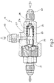
- the three-way valve 11 ( Figure 3 ) comprises a U-shaped connecting body which presents two opposing, mutually coaxial inlets 21, 22 and an outlet 23 placed at right angle in relation to the axis of the inlets 21, 22 ; the latter are respectively linked, the inlet 22 to the main braking circuit and the inlet 21 to the delivery 16 of the pump 10 ; on the contrary, the outlet 23 is linked to the braking circuit 6 of the rear axis .
- a shuttle 24 Inside the body 20, in a chamber 27 coaxial to the inlets 21, 22, there is slidingly mobile a shuttle 24, the opposite extremities of which are arranged to fluid-tight cooperate with respective sealing seats 25, 26 corresponding to the inlets 21, 22 to selectively open/close the communication between them and the chamber 27, and on which the pressure generated by the pump 4 and the pressure genarated by the pump 10 respectively operate .
- the shuttle 24 kept in position by a spring 27a, keeps the inlet 21 closed and, simultaneously, enables the inlet 22 to communicate with the outlet 23 through the chamber 27 ; in the opposite position, not shown for simplicity, the shuttle 24 reverses the connections by closing the inlet 22 and connecting the inlet 21 with the outlet 23 .
- the lever 8 is idle-hinged within a U-shaped stirrup 30 delimited by respective substantially triangular side walls 31 : in particular, an extreme end 32 of the lever 8 is fulcrumed on a transverse tubular pin 33 fitted through the walls 31 on corresponding lower parts of the latter ; in that way the lever 8 and the stirrup 30 are rigidly coupled and reciprocally rotating, being able to part from one another as two scissors blades ; the stirrup 30 is in its turn idle-hinge-holded by a second stirrup 34, fixed, rigidly mountable by means of screws on a fixed support plate 35 within the passenger compartment and holding the pump 10 secured in the proper position ; in particular, the stirrup 30 is hinged to the stirrup 34, coaxial to the hinging axis of the lever 8 on the stirrup 30 itself, for example by means of a pin 38 fitted through the stirrup 34 and housed within the tubular pin 33 ; on the upper part, on a vertex 39 of the
- the stirrup 30 there is cantilever-fastened, in a rigid manner (for example welded), in the direction of the lever 8, a shoulder consisting of a cap 44 ; between the latter and a supporting cone 44 rigid with the lever 8 there is inserted the spring 12, in the present case a helical spring, so as to be pack-tightened between the lever 8 and the stirrup 30 and, therefore, to be able to keep them apart from one another ;
- the rachet gear 9 is partly holded by the fixed stirrup 34, on which there is laterally provided a sector gear 46 rigid with it, and partly by the lever 8 the extremity 32 of which is laterally cantilever-provided with a pawl 47 engaging the sector gear 46 ; in order to control-disengage the rachet gear 9 the pawl 47 is linked, by means of a well-known driving gear 48 housed within the lever 8, to a release pusher 49 mobile against the action of a spring 50 and placed at the extremity of a handle
- the braking power produced by the pump 4 with the cooperation of the spring 27a normally keeps the shuttle 24 in the position illustrated in Figure 3 and the lever is kept lowered almost horizontally, substantially in the position illustrated in Figure 1 ; in that way the pressurized oil sent by the pump 4 runs from the circuit 2 to the circuit 6, through the valve 11, operating the vehicle hydraulic service brakes 7 whenever necessary .
- the user may obtain the parking or, respectively, the emergency braking by pulling the lever 8 .
- the user will grasp the handle 51 and lift the lever 8 rotating it in the direction of the arrow head ( Figure 1 ) .
- the user operates on the pusher 49, just as with the well-known hand brakes, producing its moving backward against the action of the spring 50 .
Landscapes
- Engineering & Computer Science (AREA)
- Transportation (AREA)
- Mechanical Engineering (AREA)
- Valves And Accessory Devices For Braking Systems (AREA)
- Braking Elements And Transmission Devices (AREA)
- Braking Arrangements (AREA)
Claims (3)
- Not- und Feststellbremsvorrichtung eines Fahrzeugs von der Art, die eine Hydropumpe (10) umfaßt, die von einem Bedienungshebel (8) betätigt wird und über ein Dreiwegeventil (11) mit einem Bremskreis des Fahrzeugs verbunden ist, dadurch gekennzeichnet, daß die Vorrichtung außerdem einen im Fahrgastraum des Fahrzeugs montierbaren und von Hand anhebbaren Bedienungshebel (8) zur Betätigung der Pumpe (10), ein Rastgetriebe (9), das durch das Anheben des Hebels aktivierbar ist und ein Absenken des Hebels (8) verhindert, und Mittel zum Lösen des Rastgetriebes aufweist, wobei der Hebel (8) gegen den Widerstand eines Spanngliedes (12) anhebbar ist, das so angeordnet ist, daß es in entgegengesetzter Richtung auf das Rastgetriebe und die Pumpe wirkt, die über das Dreiwegeventil (11) mit dem Bremskreis (6) von einer Achse des Fahrzeugs verbunden ist, sowie dadurch, daß der Hebel (8) in einer U-förmigen Konsole (30) mit Leerhub schwenkbar gelagert und am offenen Teil mit dem Kopf einer Zugstange (14) der Pumpe gelenkig verbunden ist, wobei die U-förmige Konsole (30) ihrerseits mit Leerhub schwenkbar in einer feststehenden Konsole (34) gelagert ist, die mit einem starren Zahnsegment des Rastgetriebes (9) versehen ist, das mit einer entsprechenden, seitlich am Hebel (8) vorstehenden Sperrklinke (47) zusammenwirkt und wobei zwischen letzterer und einem Anschlag (44), der mit der U-förmigen Konsole nahe am offenen Teil der Konsole fest verbunden ist, eine Feder (12) eingespannt ist, die in der Lage ist, den Hebel (8) und die U-förmige Konsole (30) auseinanderzuhalten.
- Vorrichtung nach Anspruch 1, dadurch gekennzeichnet, daß die Hydropumpe (10) umfaßt- eine verschiebbare Steuerstange (14), die mit dem Hebel gelenkig verbunden ist,- einen Einlaß-Anschluß (15), der über eine Nebenleitung mit einem Öl-Behälter des Hauptkreises (2) des Betriebs-Bremssystems des Fahrzeugs verbunden ist, und- einen Auslaßanschluß (16), der über das Dreiwegeventil (11) mit dem Bremskreis (6) verbunden ist, der Teil des Betriebs-Bremssystems (1) ist und ebenfalls über das Dreiwegeventil (11) mit dem Hauptkreis (2) des Betriebs-Bremssystems verbunden ist.
- Vorrichtung nach Anspruch 2, dadurch gekennzeichnet, daß das Dreiwegeventil (11) umfaßt- ein Anschluß-Gehäuse mit zwei gegenüberliegenden Einlässen (21, 22), die mit dem Hauptbremskreis bzw. mit dem Auslaß-Anschluß der Hydropumpe (10) verbunden sind,- einen Auslaß (23), der mit dem Bremskreis (6) einer Achse des Fahrzeugs verbunden ist, und- einen Pendelkolben (24), der im Gehäuse in Abhängigkeit von der Differenz des Druckes zwischen den beiden Einlässen (21, 22) beweglich und in der Lage ist, den Auslaß wahlweise mit einem der Einlässe zu verbinden.
Applications Claiming Priority (2)
| Application Number | Priority Date | Filing Date | Title |
|---|---|---|---|
| IT6734890 | 1990-05-11 | ||
| IT06734890A IT1248418B (it) | 1990-05-11 | 1990-05-11 | Dispositivo per la frenatura di soccorso e stazionamento di un veicolo |
Publications (2)
| Publication Number | Publication Date |
|---|---|
| EP0456097A1 EP0456097A1 (de) | 1991-11-13 |
| EP0456097B1 true EP0456097B1 (de) | 1996-01-10 |
Family
ID=11301659
Family Applications (1)
| Application Number | Title | Priority Date | Filing Date |
|---|---|---|---|
| EP91107045A Expired - Lifetime EP0456097B1 (de) | 1990-05-11 | 1991-04-30 | Not- und Feststelllbremsvorrichtung eines Fahrzeugs |
Country Status (3)
| Country | Link |
|---|---|
| EP (1) | EP0456097B1 (de) |
| DE (1) | DE69116213T2 (de) |
| IT (1) | IT1248418B (de) |
Families Citing this family (6)
| Publication number | Priority date | Publication date | Assignee | Title |
|---|---|---|---|---|
| DE4211566A1 (de) * | 1992-04-07 | 1993-10-14 | Scharwaechter Gmbh Co Kg | Mit einer selbsttätigen Nachstelleinrichtung versehene Handbremse |
| DE19521159C2 (de) * | 1995-06-09 | 1998-05-14 | Porsche Ag | Betätigungsvorrichtung für eine Feststellbremse |
| DE19815708C2 (de) * | 1998-04-08 | 2000-05-25 | Daimler Chrysler Ag | Feststellbremsvorrichtung für ein Fahrzeug |
| DE19836017A1 (de) * | 1998-08-10 | 2000-02-17 | Bayerische Motoren Werke Ag | Verfahren zur Bemessung der Bremskraft |
| EP2962912B1 (de) * | 2014-07-02 | 2019-09-04 | Safim S.p.A. | Bremsvorrichtung |
| CN113859204A (zh) * | 2021-11-02 | 2021-12-31 | 浙江浦数科技有限公司 | 一种新能源汽车专用制动阀 |
Family Cites Families (4)
| Publication number | Priority date | Publication date | Assignee | Title |
|---|---|---|---|---|
| SE353280B (de) * | 1969-11-03 | 1973-01-29 | Saab Scania Ab | |
| US3680314A (en) * | 1969-11-19 | 1972-08-01 | Francis J Toomey | Hydraulic emergency brake system |
| DE3045888C2 (de) * | 1980-12-05 | 1983-08-11 | Daimler-Benz Ag, 7000 Stuttgart | Hydraulische Bremsanlage |
| GB8416367D0 (en) * | 1984-06-27 | 1984-08-01 | Lucas Ind Plc | Hydraulic braking systems |
-
1990
- 1990-05-11 IT IT06734890A patent/IT1248418B/it active IP Right Grant
-
1991
- 1991-04-30 DE DE69116213T patent/DE69116213T2/de not_active Expired - Fee Related
- 1991-04-30 EP EP91107045A patent/EP0456097B1/de not_active Expired - Lifetime
Also Published As
| Publication number | Publication date |
|---|---|
| IT1248418B (it) | 1995-01-16 |
| DE69116213D1 (de) | 1996-02-22 |
| DE69116213T2 (de) | 1996-05-30 |
| IT9067348A0 (it) | 1990-05-11 |
| EP0456097A1 (de) | 1991-11-13 |
| IT9067348A1 (it) | 1991-11-11 |
Similar Documents
| Publication | Publication Date | Title |
|---|---|---|
| CA2823723C (en) | Parking brake assembly for railway vehicle brake system | |
| CA2235715C (en) | Cable reel handler | |
| CN117241983A (zh) | 自动列车耦连装置和用于使自动列车耦连装置脱耦的方法 | |
| EP0268183A2 (de) | Feststellbremsanlage für Schienenfahrzeuge | |
| EP0456097A1 (de) | Not- und Feststelllbremsvorrichtung eines Fahrzeugs | |
| US3838572A (en) | Operating device for an assisted system with an energy accumulator | |
| US5154491A (en) | Emergency and parking brake system | |
| EP1914136A1 (de) | Feststellbremse mit Sicherheitsvorrichtung, im Besonderen für einen Ackerschlepper | |
| CA3012289C (en) | System for raising and lowering vehicle | |
| US5113977A (en) | Lift truck parking brake | |
| US5601162A (en) | Spring applied automative parking brake system | |
| US4275870A (en) | Apparatus for controlling speed and direction of a vehicular towing winch | |
| US3848692A (en) | Dual brake on drive and idler wheels of industrial trucks | |
| AU2018200798B2 (en) | Automatic parking brake for truck mounted brake cylinder | |
| EP3365206B1 (de) | Ein hydraulischer bremsaktor | |
| CN212685515U (zh) | 一种拖拉机刹车装置及拖拉机 | |
| JP2002506770A (ja) | オートバイのスタンドを操作するためのアクチュエータ装置及び自動的に解除可能なハイドロリックバルブ | |
| US4015698A (en) | Actuating mechanism for pressurized fluid brake system and fail-safe locking device therefor | |
| US7048095B1 (en) | Hydraulically actuated parking brake | |
| US3031036A (en) | Emergency brake mechanism | |
| CN113226847A (zh) | 用于车载货物运输系统的锁定系统及设置有该锁定系统的机动车辆 | |
| US3292452A (en) | Combined hand brake for vehicles | |
| JPS6326978Y2 (de) | ||
| JPH092135A (ja) | タンクローリの底弁操作装置 | |
| KR20020047935A (ko) | 주차브레이크 케이블 장력 조절 장치 |
Legal Events
| Date | Code | Title | Description |
|---|---|---|---|
| PUAI | Public reference made under article 153(3) epc to a published international application that has entered the european phase |
Free format text: ORIGINAL CODE: 0009012 |
|
| AK | Designated contracting states |
Kind code of ref document: A1 Designated state(s): DE ES FR GB SE |
|
| 17P | Request for examination filed |
Effective date: 19920429 |
|
| 17Q | First examination report despatched |
Effective date: 19930719 |
|
| GRAA | (expected) grant |
Free format text: ORIGINAL CODE: 0009210 |
|
| AK | Designated contracting states |
Kind code of ref document: B1 Designated state(s): DE ES FR GB SE |
|
| PG25 | Lapsed in a contracting state [announced via postgrant information from national office to epo] |
Ref country code: ES Free format text: THE PATENT HAS BEEN ANNULLED BY A DECISION OF A NATIONAL AUTHORITY Effective date: 19960110 |
|
| REF | Corresponds to: |
Ref document number: 69116213 Country of ref document: DE Date of ref document: 19960222 |
|
| ET | Fr: translation filed | ||
| PG25 | Lapsed in a contracting state [announced via postgrant information from national office to epo] |
Ref country code: SE Effective date: 19960410 |
|
| PLBE | No opposition filed within time limit |
Free format text: ORIGINAL CODE: 0009261 |
|
| STAA | Information on the status of an ep patent application or granted ep patent |
Free format text: STATUS: NO OPPOSITION FILED WITHIN TIME LIMIT |
|
| 26N | No opposition filed | ||
| REG | Reference to a national code |
Ref country code: GB Ref legal event code: IF02 |
|
| PGFP | Annual fee paid to national office [announced via postgrant information from national office to epo] |
Ref country code: GB Payment date: 20030430 Year of fee payment: 13 |
|
| PGFP | Annual fee paid to national office [announced via postgrant information from national office to epo] |
Ref country code: FR Payment date: 20040429 Year of fee payment: 14 |
|
| PG25 | Lapsed in a contracting state [announced via postgrant information from national office to epo] |
Ref country code: GB Free format text: LAPSE BECAUSE OF NON-PAYMENT OF DUE FEES Effective date: 20040430 |
|
| PGFP | Annual fee paid to national office [announced via postgrant information from national office to epo] |
Ref country code: DE Payment date: 20040624 Year of fee payment: 14 |
|
| GBPC | Gb: european patent ceased through non-payment of renewal fee |
Effective date: 20040430 |
|
| PG25 | Lapsed in a contracting state [announced via postgrant information from national office to epo] |
Ref country code: DE Free format text: LAPSE BECAUSE OF NON-PAYMENT OF DUE FEES Effective date: 20051101 |
|
| PG25 | Lapsed in a contracting state [announced via postgrant information from national office to epo] |
Ref country code: FR Free format text: LAPSE BECAUSE OF NON-PAYMENT OF DUE FEES Effective date: 20051230 |
|
| REG | Reference to a national code |
Ref country code: FR Ref legal event code: ST Effective date: 20051230 |