EP1911878A2 - Stoffauflauf - Google Patents
Stoffauflauf Download PDFInfo
- Publication number
- EP1911878A2 EP1911878A2 EP07118009A EP07118009A EP1911878A2 EP 1911878 A2 EP1911878 A2 EP 1911878A2 EP 07118009 A EP07118009 A EP 07118009A EP 07118009 A EP07118009 A EP 07118009A EP 1911878 A2 EP1911878 A2 EP 1911878A2
- Authority
- EP
- European Patent Office
- Prior art keywords
- nozzle
- offset
- headbox
- diaphragm
- lip
- Prior art date
- Legal status (The legal status is an assumption and is not a legal conclusion. Google has not performed a legal analysis and makes no representation as to the accuracy of the status listed.)
- Granted
Links
Images

Classifications
-
- D—TEXTILES; PAPER
- D21—PAPER-MAKING; PRODUCTION OF CELLULOSE
- D21F—PAPER-MAKING MACHINES; METHODS OF PRODUCING PAPER THEREON
- D21F1/00—Wet end of machines for making continuous webs of paper
- D21F1/02—Head boxes of Fourdrinier machines
-
- D—TEXTILES; PAPER
- D21—PAPER-MAKING; PRODUCTION OF CELLULOSE
- D21F—PAPER-MAKING MACHINES; METHODS OF PRODUCING PAPER THEREON
- D21F1/00—Wet end of machines for making continuous webs of paper
- D21F1/02—Head boxes of Fourdrinier machines
- D21F1/028—Details of the nozzle section
Definitions
- the invention relates to a headbox for a machine for producing a fibrous web, in particular paper or board web, with a nozzle for producing a suspension jet comprising a first lip provided with a diaphragm and a second lip opposite thereto, wherein a nozzle channel between the two nozzle lips defined and the aperture is provided in the region of the nozzle outlet opening. It further relates to a two-layer casserole according to the preamble of claim 12.
- Such a headbox of the type mentioned is, for example, from the DE 43 23 050 C1 known.
- One of the two nozzle lips of a headbox is usually smooth in the flow direction and projects beyond the aperture provided on the opposite nozzle lip.
- the smooth shape ensures that there is no beam contraction and thus suspension acceleration.
- the suspension jet is contracted on the baffle side of the headbox and the suspension accelerated accordingly, resulting in different flow conditions on the top and bottom of the suspension jet and ultimately in the paper in terms of speed and turbulence.
- different degrees of orientation in the z-direction of the fibrous web can be generated.
- the result may be curls (curling), for example, in copy paper or other flatness problems (cockling, fluting).
- a first nozzle lip 12 provided with a diaphragm faces a smooth second nozzle lip 14.
- the diaphragm 10 protrudes toward the opposite second nozzle lip 14 so that the suspension or material jet 16 contracts on the diaphragm side of the headbox and the suspension is correspondingly accelerated.
- the invention has for its object to provide an improved headbox or two-layer casserole of the type mentioned, in which the suspension jet generated in terms of speed and turbulence in the thickness or z-direction has a greater symmetry, whereby the quality of the final product and in particular the flatness is improved.
- a partial control of the profiling should be possible in the z direction, if a symmetrical paper is not yet optimal for the application.
- this object is achieved in that the second nozzle lip has a projecting towards the center plane of the nozzle channel offset.
- the suspension jet is contracted and accelerated on the relevant side, so that it receives at least a similar characteristic with respect to turbulence and speed as on the diaphragm side.
- the distance between the offset and the center plane of the nozzle channel is at least substantially the same size as the distance between the aperture and the median plane of the nozzle channel.
- the offset relative to the plane of the surface of the second nozzle lip adjoining the nozzle channel can advantageously protrude by an amount which is in the range of the amount by which the aperture is opposite that of the nozzle channel protruding surface of the first nozzle lip protrudes.
- the offset and the diaphragm are advantageously present in each case by an amount in the range of about 0.2 to about 0.6 mm, preferably by an amount in the range of about 0.5 to 0.3 mm.
- the offset expediently begins before or after the diaphragm in the direction of the suspension jet.
- this offset When the offset starts in the direction of the suspension jet, viewed in front of the orifice, this offset, viewed in the direction of the jet of suspension, can extend beyond the end of the first die lip provided with the orifice.
- the portion of the offset lying in front of the panel is shorter in the direction of the suspension jet than the portion of the offset lying behind the panel.
- the offset is arranged at least substantially symmetrically with respect to the diaphragm.
- the portions of the offset lying in front of and behind the diaphragm can thus also be at least substantially equal in length.
- the offset in the direction of the suspension jet can also begin only after the diaphragm.
- embodiments are also conceivable in which the offset begins in the region of the diaphragm, However, preferred embodiments in which this offset begins before or after the aperture.
- the offset can be provided in particular in the manner of a stage.
- the transition between the adjacent to the nozzle channel surface of the second nozzle lip and the offset is rounded.
- the geometry of the offset is preferably designed as a curve without sharp edges, a flow separation of the respective nozzle wall and consequently deposits and jet disturbances are avoided.
- the headbox according to the invention is advantageously used in particular as a single-layer headbox and for wood-free papers.
- the generated suspension jet can be made more symmetrical in terms of speed and turbulence in the thickness or in the z-direction, whereby the paper quality can be improved accordingly and in particular a flat layer can be produced. If a symmetrical paper should not be optimal for the application, the profiling in the z-direction can be partially controlled due to the inventive solution.
- the above-mentioned object is achieved in that the nozzle is divided by the lamella in two symmetrical nozzle channels, that in each case one aperture is provided in the region of the nozzle outlet opening at each of the two of the lamella opposite the lamella and that the two diaphragms are arranged or jointly adjustable so that they protrude toward the slat by at least substantially the same amount.
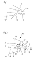
- Figure 2 shows a schematic partial representation of an exemplary embodiment of a headbox 18 according to the invention for a machine for producing a fibrous web, in particular paper or board web.
- the headbox 18 comprises a nozzle 20 for generating a suspension jet, which has a first lip 24 provided with a diaphragm 22 and a second lip 26 opposite thereto. Between the two Nozzle lips 24, 26, a nozzle channel 28 is defined. The aperture 22 is provided in the region of the nozzle outlet opening 30.
- the second nozzle lip 26 has an offset 34 which projects toward the center plane 32 of the nozzle channel 28.
- the distance between the offset 34 and the center plane 32 of the nozzle channel 28 is at least substantially equal to the distance between the aperture 22 and the central plane 32 of the nozzle channel 28 at least substantially.
- the offset 34 can thus protrude with respect to the plane 36 'of the surface 36 of the second nozzle lip 26 adjoining the nozzle channel 38 by an amount 38 which lies in the region of the amount 40 in that the diaphragm 22 protrudes from the surface 42 of the first nozzle lip 24 adjoining the nozzle channel 28.
- the offset 34 begins in the direction of the suspension jet 44 viewed in front of the diaphragm 22. In this case, the offset 34 extends in the direction of the suspension jet 44 beyond the end of the first nozzle lip 24 provided with the diaphragm 22.
- transition between adjacent to the nozzle channel 28 surface 26 of the second nozzle lip 26 and the offset 34 is advantageously rounded, as indicated in Figure 2 by an arrow labeled "R” arrow. Also the Transition between the edge 46 and the adjoining to the mid-plane 32 parallel portion of the offset 34 is rounded again. This rounding is again indicated by an arrow marked "R”.
- the offset 34 begins at a distance l 'in front of the diaphragm 22.
- FIG. 3 shows, in a schematic partial representation, a further embodiment of the head box 18 according to the invention, which differs substantially from that of FIG. 2 only in that the offset 34, viewed in the direction of the suspension jet 44, does not begin until after the panel 22
- this embodiment may be at least substantially reconstructed as that of Figure 2, wherein like reference numerals are assigned to corresponding parts.
- FIG. 4 shows, in a schematic partial representation, an exemplary embodiment of a two-layer headbox 48 according to the invention for a machine for producing a fibrous web, in particular a paper or board web.
- the two-layer headbox 48 comprises a nozzle 52 divided by a machine-wide lamella 50 for forming two nozzle channels 54, 56 between a respective nozzle wall 58 or 60 and the lamella 50.
- the nozzle 52 is divided by the blade 50 in two symmetrical, a fabric A leading nozzle channels 54, 56.
- an aperture 64 or 66 is respectively provided on each of the two nozzle walls 58 and 60 opposite the lamella 50.
- the two panels 64, 66 are arranged or jointly adjustable so that they protrude to an at least substantially equal amount to the fin 50 out.
Landscapes
- Paper (AREA)
- Magnetic Resonance Imaging Apparatus (AREA)
Abstract
Description
- Die Erfindung betrifft einen Stoffauflauf für eine Maschine zur Herstellung einer Faserstoffbahn, insbesondere Papier- oder Kartonbahn, mit einer Düse zur Erzeugung eines Suspensionsstrahles, die eine mit einer Blende versehene erste Lippe und eine dieser gegenüberliegende zweite Lippe umfasst, wobei zwischen den beiden Düsenlippen ein Düsenkanal definiert und die Blende im Bereich der Düsenaustrittsöffnung vorgesehen ist. Sie betrifft ferner einen Zweischichtstoffauflauf gemäß dem Oberbegriff des Anspruchs 12.
- Ein solcher Stoffauflauf der eingangs genannten Art ist beispielsweise aus der
DE 43 23 050 C1 bekannt. - Eine der beiden Düsenlippen eines Stoffauflaufs ist üblicherweise in Strömungsrichtung glatt und über die an der gegenüberliegenden Düsenlippe vorgesehene Blende überstehend. Die glatte Form sorgt dafür, dass es zu keiner Strahlkontraktion und damit Suspensionsbeschleunigung kommt.
- Im Gegensatz dazu wird auf der Blendenseite des Stoffauflaufs der Suspensionsstrahl kontrahiert und die Suspension entsprechend beschleunigt, wodurch sich hinsichtlich Geschwindigkeit und Turbulenz unterschiedliche Strömungszustände auf der Ober- und Unterseite des Suspensionsstrahls und schließlich auch im Papier ergeben. Hierdurch können verschieden starke Orientierungen in der z-Richtung der Faserstoffbahn erzeugt werden. Die Folge können Curl-Erscheinungen (Rollneigung) zum Beispiel im Kopierpapier oder andere Flachlagenprobleme (Cockling, Fluting) sein.
- Die entsprechenden Verhältnisse bei einem derartigen bekannten Stoffauflauf ergeben sich aus der Figur 1, in der auch die Strahlkonstraktion "K" des Suspensionsstrahls 16 dargestellt ist.
- Danach liegt einer mit einer Blende versehenen ersten Düsenlippe 12 eine glatte zweite Düsenlippe 14 gegenüber. Die Blende 10 steht zur gegenüberliegenden zweiten Düsenlippe 14 hin vor, so dass auf der Blendenseite des Stoffauflaufs der Suspensions- oder Stoffstrahl 16 kontrahiert und die Suspension entsprechend beschleunigt wird.
- Der Erfindung liegt die Aufgabe zugrunde, einen verbesserten Stoffauflauf bzw. Zweischichtstoffauflauf der eingangs genannten Art zu schaffen, bei dem der erzeugte Suspensionsstrahl im Hinblick auf Geschwindigkeit und Turbulenz in Dicken- oder z-Richtung eine größere Symmetrie besitzt, wodurch die Qualität des Endproduktes und insbesondere die Flachlage verbessert wird. Zudem soll in z-Richtung eine teilweise Steuerung der Profilierung möglich sein, falls ein symmetrisches Papier noch nicht optimal für den Einsatzfall ist.
- Bezüglich des Stoffauflaufs der eingangs genannten Art wird diese Aufgabe erfindungsgemäß dadurch gelöst, dass die zweite Düsenlippe einen zur Mittenebene des Düsenkanals hin vorspringenden Versatz aufweist.
- Durch den Versatz wird der Suspensionsstrahl auf der betreffenden Seite kontrahiert und beschleunigt, so dass er in Bezug auf Turbulenz und Geschwindigkeit zumindest eine ähnliche Charakteristik wie auf der Blendenseite erhält.
- Bevorzugt ist in der Ebene der Düsenaustrittsöffnung oder in einer dazu parallelen Ebene betrachtet der Abstand zwischen dem Versatz und der Mittelebene des Düsenkanals zumindest im Wesentlichen gleich groß wie der Abstand zwischen der Blende und der Mittelebene des Düsenkanals.
- In der Ebene der Düsenaustrittsöffnung oder in einer dazu parallelen Ebene betrachtet kann also der Versatz gegenüber der Ebene der an den Düsenkanal angrenzenden Fläche der zweiten Düsenlippe vorteilhafterweise um einen Betrag vorstehen, der im Bereich des Betrages liegt, um den die Blende gegenüber der an den Düsenkanal angrenzenden Fläche der ersten Düsenlippe vorsteht.
- Dabei stehen der Versatz und die Blende, das heißt die Blendenkante vorteilhafterweise jeweils um einen Betrag im Bereich von etwa 0,2 bis etwa 0,6 mm, bevorzugt um einen Betrag im Bereich von etwa 0,5 bis 0,3 mm vor.
- Zur Vermeidung von Strahlinstabilitäten beginnt der Versatz in Richtung des Suspensionsstrahles betrachtet zweckmäßigerweise vor oder nach der Blende.
- Beginnt der Versatz in Richtung des Suspensionsstrahles betrachtet vor der Blende, so kann sich dieser Versatz in Richtung des Suspensionsstrahls betrachtet über das mit der Blende versehene Ende der ersten Düsenlippe hinaus erstrecken.
- Bei einer zweckmäßigen praktischen Ausführungsform des erfindungsgemäßen Stoffauflaufs ist in Richtung des Suspensionsstrahles betrachtet der vor der Blende liegende Abschnitt des Versatzes kürzer als der hinter der Blende liegende Abschnitt des Versatzes.
- Gemäß einer alternativen vorteilhaften Ausführungsform ist in Richtung des Suspensionsstrahles betrachtet der Versatz zumindest im Wesentlichen symmetrisch zur Blende angeordnet. Die vor und hinter der Blende liegenden Abschnitte des Versatzes können also auch zumindest im Wesentlichen gleich lang sein.
- Wie bereits erwähnt, kann der Versatz in Richtung des Suspensionsstrahles betrachtet auch erst nach der Blende beginnen. Grundsätzlich sind zwar auch Ausführungen denkbar, bei denen der Versatz im Bereich der Blende beginnt, bevorzugt sind jedoch Ausführungen, bei denen dieser Versatz vor oder nach der Blende beginnt.
- Der Versatz kann insbesondere nach Art einer Stufe vorgesehen sein.
- Von Vorteil ist insbesondere auch, wenn der Übergang zwischen der an den Düsenkanal angrenzenden Fläche der zweiten Düsenlippe und dem Versatz gerundet ist. Indem die Geometrie des Versatzes bevorzugt als Kurve ohne scharfe Kanten ausgeführt ist, werden eine Strömungsablösung von der betreffenden Düsenwand und demzufolge Ablagerungen und Strahlstörungen vermieden.
- Der erfindungsgemäße Stoffauflauf ist mit Vorteil insbesondere als Einschichtstoffauflauf und für holzfreie Papiere einsetzbar.
- Er ist mit besonderem Vorteil insbesondere bei GapFormern einsetzbar, bei denen die Blattstruktur durch die Geschwindigkeitsunterschiede der Stoffsuspension auf verschiedenen Radien um gebogene Elemente beeinflusst wird, um eine symmetrische oder beliebig gesteuerte Faserorientierungszweiseitigkeit zu erreichen.
- Demzufolge kann insbesondere ein Papier erzeugt werden, welches nach dem Kopieren nur noch eine sehr geringe Rollneigung besitzt.
- Der erzeugte Suspensionsstrahl kann bezüglich der Geschwindigkeit und Turbulenz in der Dicke oder in z-Richtung symmetrischer gemacht werden, wodurch die Papierqualität entsprechend verbessert und insbesondere eine Flachlage erzeugt werden kann. Sofern ein symmetrisches Papier noch nicht optimal für den Einsatzfall sein sollte, kann aufgrund der erfindungsgemäßen Lösung die Profilierung in z-Richtung teilweise gesteuert werden.
- Bezüglich des Zweischichtstoffauflaufs der eingangs genannten Art wird die weiter oben angegebene Aufgabe erfindungsgemäß dadurch gelöst, dass die Düse durch die Lamelle in zwei symmetrische Düsenkanäle unterteilt ist, dass im Bereich der Düsenaustrittöffnung an jeder der beiden der Lamelle gegenüberliegenden Düsenwände jeweils eine Blende vorgesehen ist und dass die beiden Blenden so angeordnet bzw. gemeinsam so verstellbar sind, dass sie um einen zumindest im Wesentlichen gleichen Betrag zur Lamelle hin vorstehen.
- Damit ergeben sich zwei symmetrische Teildüsen bzw. Düsenkanäle mit symmetrischen Profilen in z-Richtung, die jeweils ein Geschwindigkeitsprofil bilden, wodurch sich insgesamt zum Beispiel ein Turbulenzprofil ergibt.
- Die Erfindung wird im Folgenden anhand von Ausführungsbeispielen unter Bezugnahme auf die Zeichnung näher erläutert; in dieser zeigen:
- Figur 1
- eine schematische Teildarstellung eines herkömmlichen Stoffauflaufs;
- Figur 2
- eine schematische Teildarstellung einer beispielhaften Ausführungsform eines erfindungsgemäßen Stoffauflaufs,
- Figur 3
- eine schematische Teildarstellung einer weiteren Ausführungsform des erfindungsgemäßen Stoffauflaufs, und
- Figur 4
- eine schematische Teildarstellung einer beispielhaften Ausführungsform eines erfindungsgemäßen Zweischichtstoffauflaufs.
- Figur 2 zeigt in schematischer Teildarstellung eine beispielhafte Ausführungsform eines erfindungsgemäßen Stoffauflaufs 18 für eine Maschine zur Herstellung einer Faserstoffbahn, insbesondere Papier- oder Kartonbahn.
- Der Stoffauflauf 18 umfasst eine Düse 20 zur Erzeugung eines Suspensionsstrahles, die eine mit einer Blende 22 versehene erste Lippe 24 und eine dieser gegenüberliegende zweite Lippe 26 aufweist. Zwischen den beiden Düsenlippen 24, 26 ist ein Düsenkanal 28 definiert. Die Blende 22 ist im Bereich der Düsenaustrittsöffnung 30 vorgesehen.
- Wie anhand der Figur 2 zu erkennen ist, weist die zweite Düsenlippe 26 eine zur Mittenebene 32 des Düsenkanals 28 hin vorspringenden Versatz 34 auf.
- In der Ebene der Düsenaustrittsöffnung 30 oder in einer dazu parallelen Ebene betrachtet ist der Abstand zwischen dem Versatz 34 und der Mittenebene 32 des Düsenkanals 28 zumindest im Wesentlichen vorzugsweise gleich groß wie der Abstand zwischen der Blende 22 und der Mittenebene 32 des Düsenkanals 28.
- In der Ebene der Düsenaustrittsöffnung 30 oder in einer dazu parallelen Ebene betrachtet kann der Versatz 34 also gegenüber der Ebene 36' der an dem Düsenkanal 38 angrenzenden Fläche 36 der zweiten Düsenlippe 26 um einen Betrag 38 vorstehen, der im Bereich des Betrages 40 liegt, um den die Blende 22 gegenüber der an den Düsenkanal 28 angrenzenden Fläche 42 der ersten Düsenlippe 24 vorsteht.
- Im vorliegenden Fall beginnt der Versatz 34 in Richtung des Suspensionsstrahles 44 betrachtet vor der Blende 22. Dabei erstreckt sich der Versatz 34 in Richtung des Suspensionsstrahles 44 betrachtet über das mit der Blende 22 versehene Ende der ersten Düsenlippe 24 hinaus.
- Im vorliegenden Fall ist der in Richtung des Suspensionsstrahles 44 betrachtet vor der Blende 22 liegende Abschnitt des Versatzes 34 beispielsweise kürzer als der dahinterliegende Abschnitt. Es ist beispielsweise jedoch auch eine in Richtung des Suspensionsstrahles 44 betrachtet zumindest im Wesentlichen symmetrische Anordnung des Versatzes relativ zur Blende 22 denkbar.
- Der Übergang zwischen der an dem Düsenkanal 28 angrenzenden Fläche 26 der zweiten Düsenlippe 26 und dem Versatz 34 ist vorteilhafterweise gerundet, wie dies in der Figur 2 durch einen mit "R" bezeichneten Pfeil angedeutet ist. Auch der Übergang zwischen der Flanke 46 und dem sich daran anschließenden zur Mittenebene 32 parallelen Abschnitt des Versatzes 34 ist wieder gerundet. Auch diese Rundung ist wieder durch einen mit "R" bezeichneten Pfeil angedeutet.
- Wie anhand der Figur 2 zu erkennen ist, beginnt der Versatz 34 in einem Abstand I' vor der Blende 22.
- Figur 3 zeigt in schematischer Teildarstellung eine weitere Ausführungsform des erfindungsgemäßen Stoffauflaufs 18, die sich von der der Figur 2 im Wesentlichen nur dadurch unterscheidet, dass der Versatz 34 in Richtung des Suspensionsstrahles 44 betrachtet erst in einem Abstand I" nach der Blende 22 beginnt. Im Übrigen kann diese Ausführungsform zumindest im Wesentlichen wieder so aufgebaut sein wie die der Figur 2, wobei einander entsprechenden Teilen gleiche Bezugszeichen zugeordnet sind.
- Figur 4 zeigt in schematischer Teildarstellung eine beispielhafte Ausführungsform eines erfindungsgemäßen Zweischichtstoffauflaufs 48 für eine Maschine zur Herstellung einer Faserstoffbahn, insbesondere Papier- oder Kartonbahn.
- Wie anhand der Figur 4 zu erkennen ist, umfasst der Zweischichtstoffauflauf 48 eine durch eine maschinenbreite Lamelle 50 unterteilte Düse 52 zur Bildung zweier Düsenkanäle 54, 56 zwischen einer jeweiligen Düsenwand 58 bzw. 60 und der Lamelle 50.
- Dabei ist die Düse 52 durch die Lamelle 50 in zwei symmetrische, einen Stoff A führende Düsenkanäle 54, 56 unterteilt. Im Bereich der Düsenaustrittsöffnung 62 ist an jeder der beiden der Lamelle 50 gegenüberliegenden Düsenwände 58 bzw. 60 jeweils eine Blende 64 bzw. 66 vorgesehen. Dabei sind die beiden Blenden 64, 66 so angeordnet bzw. gemeinsam so verstellbar, dass sie um einen zumindest im Wesentlichen gleichen Betrag zur Lamelle 50 hin vorstehen.
- Damit ergeben sich also zwei symmetrische Düsen bzw. Düsenkanäle 54, 56 mit symmetrischen Profilen in z-Richtung, wobei sich für jeden Düsenkanal 54, 56 jeweils ein Geschwindigkeitsprofil ergibt, was beispielsweise ein Turbulenzprofil mit sich bringt.
-
- 10
- Blende
- 12
- Erste Düsenlippe
- 14
- Zweite Düsenlippe
- 16
- Suspensionsstrahl
- 18
- Stoffauflauf
- 20
- Düse
- 22
- Blende
- 24
- Erste Düsenlippe
- 26
- Zweite Düsenlippe
- 28
- Düsenkanal
- 30
- Düsenaustrittsöffnung
- 32
- Mittenebene
- 34
- Versatz
- 36
- Fläche
- 36'
- Ebene
- 38
- Betrag
- 40
- Betrag
- 42
- Fläche
- 44
- Suspensionsstrahl
- 46
- Fläche
- 48
- Zweischichtstoffauflauf
- 50
- Lamelle
- 52
- Düse
- 54
- Düsenkanal
- 56
- Düsenkanal
- 58
- Düsenwand
- 60
- Düsenwand
- 62
- Düsenaustrittsöffnung
- 64
- Blende
- 66
- Blende
- K
- Strahlkontraktion
- I'
- Abstand
- I"
- Abstand
Claims (12)
- Stoffauflauf (18) für eine Maschine zur Herstellung einer Faserstoffbahn, insbesondere Papier- oder Kartonbahn, mit einer Düse (20) zur Erzeugung eines Suspensionsstrahles, die eine mit einer Blende (22) versehene erste Lippe (24) und eine dieser gegenüberliegende zweite Lippe (26) umfasst, wobei zwischen den beiden Düsenlippen (24, 26) ein Düsenkanal (28) definiert und die Blende (22) im Bereich der Düsenaustrittsöffnung (30) vorgesehen ist,
dadurch gekennzeichnet,
dass die zweite Düsenlippe (26) einen zur Mittenebene (32) des Düsenkanals (28) hin vorspringenden Versatz (34) aufweist. - Stoffauflauf (18) nach Anspruch 1,
dadurch gekennzeichnet,
dass in der Ebene der Düsenaustrittsöffnung (30) oder in einer dazu parallelen Ebene betrachtet der Abstand zwischen dem Versatz (34) und der Mittenebene (32) des Düsenkanals (28) zumindest im Wesentlichen gleich groß ist wie der Abstand zwischen der Blende (22) und der Mittenebene (32) des Düsenkanals (28). - Stoffauflauf (18) nach Anspruch 1 oder 2,
dadurch gekennzeichnet,
dass in der Ebene der Düsenaustrittsöffnung (30) oder in einer dazu parallelen Ebene betrachtet der Versatz (34) gegenüber der Ebene (36') der an den Düsenkanal (28) angrenzenden Fläche (36) der zweiten Düsenlippe (26) um einen Betrag (38) vorsteht, der im Bereich des Betrages (40) liegt, um den die Blende (22) gegenüber der an den Düsenkanal (28) angrenzenden Fläche (42) der ersten Düsenlippe (24) vorsteht. - Stoffauflauf (18) nach Anspruch 3,
dadurch gekennzeichnet,
dass der Versatz (34) und die Blende (22) jeweils um einen Betrag im Bereich von etwa 0,2 bis etwa 0,6 mm vorstehen. - Stoffauflauf (18) nach Anspruch 4,
dadurch gekennzeichnet,
dass der Versatz (34) und die Blende (22) jeweils um einen Betrag im Bereich von etwa 0,5 bis etwa 0,3 mm vorstehen. - Stoffauflauf (18) nach einem der vorhergehenden Ansprüche,
dadurch gekennzeichnet,
dass der Versatz (34) in Richtung des Suspensionsstrahles (44) betrachtet vor der Blende (22) beginnt. - Stoffauflauf (18) nach Anspruch 6,
dadurch gekennzeichnet,
dass sich der Versatz (34) in Richtung des Suspensionsstrahles (44) betrachtet über das mit der Blende (22) versehene Ende der ersten Düsenlippe (24) hinaus erstreckt. - Stoffauflauf (18) nach Anspruch 7,
dadurch gekennzeichnet,
dass in Richtung des Suspensionsstrahles (44) betrachtet der vor der Blende (22) liegende Abschnitt der Versatzes (34) kürzer ist als der hinter der Blende (22) liegende Abschnitt des Versatzes (34). - Stoffauflauf (18) nach Anspruch 7,
dadurch gekennzeichnet,
dass in Richtung des Suspensionsstrahles (44) betrachtet der Versatz (34) zumindest im Wesentlichen symmetrisch zur Blende (22) angeordnet ist. - Stoffauflauf (18) nach einem der Ansprüche 1 bis 5,
dadurch gekennzeichnet,
dass der Versatz (34) in Richtung des Suspensionsstrahles (44) betrachtet nach der Blende (22) beginnt. - Stoffauflauf (18) nach einem der vorhergehenden Ansprüche,
dadurch gekennzeichnet,
dass der Übergang zwischen der an den Düsenkanal (28) angrenzenden Fläche (36) der zweiten Düsenlippe (26) und dem Versatz (34) gerundet ist. - Zweischichtstoffauflauf (48) für eine Maschine zur Herstellung einer Faserstoffbahn, insbesondere Papier- oder Kartonbahn, mit einer durch eine maschinenbreite Lamelle (50) unterteilten Düse (52) zur Bildung zweier Düsenkanäle (54, 56) zwischen einer jeweiligen Düsenwand (58, 60) und der Lamelle (50),
dadurch gekennzeichnet,
dass die Düse (52) durch die Lamelle (50) in zwei symmetrische Düsenkanäle (54, 56) unterteilt ist, dass im Bereich der Düsenaustrittöffnung (60) an jeder der beiden der Lamelle (50) gegenüberliegenden Düsenwände (58, 60) jeweils eine Blende (64, 66) vorgesehen ist und dass die beiden Blenden (64, 66) so angeordnet bzw. gemeinsam so verstellbar sind, dass sie um einen zumindest im Wesentlichen gleichen Betrag zur Lamelle (50) hin vorstehen.
Priority Applications (1)
| Application Number | Priority Date | Filing Date | Title |
|---|---|---|---|
| PL07118009T PL1911878T3 (pl) | 2006-10-13 | 2007-10-08 | Doprowadzenie materiału |
Applications Claiming Priority (1)
| Application Number | Priority Date | Filing Date | Title |
|---|---|---|---|
| DE102006049020A DE102006049020A1 (de) | 2006-10-13 | 2006-10-13 | Stoffauflauf |
Publications (3)
| Publication Number | Publication Date |
|---|---|
| EP1911878A2 true EP1911878A2 (de) | 2008-04-16 |
| EP1911878A3 EP1911878A3 (de) | 2008-07-23 |
| EP1911878B1 EP1911878B1 (de) | 2010-03-31 |
Family
ID=38961120
Family Applications (1)
| Application Number | Title | Priority Date | Filing Date |
|---|---|---|---|
| EP07118009A Not-in-force EP1911878B1 (de) | 2006-10-13 | 2007-10-08 | Stoffauflauf |
Country Status (4)
| Country | Link |
|---|---|
| EP (1) | EP1911878B1 (de) |
| AT (1) | ATE462830T1 (de) |
| DE (2) | DE102006049020A1 (de) |
| PL (1) | PL1911878T3 (de) |
Cited By (1)
| Publication number | Priority date | Publication date | Assignee | Title |
|---|---|---|---|---|
| CN102691225A (zh) * | 2012-05-28 | 2012-09-26 | 华南理工大学 | 一种流浆箱装置 |
Family Cites Families (5)
| Publication number | Priority date | Publication date | Assignee | Title |
|---|---|---|---|---|
| AT376721B (de) * | 1980-11-26 | 1984-12-27 | Escher Wyss Gmbh | Stoffauflauf fuer eine papiermaschine |
| DE4005147A1 (de) * | 1990-02-17 | 1991-08-29 | Voith Gmbh J M | Verfahren und vorrichtung zum bilden einer faserstoffbahn |
| DE4323050C1 (de) * | 1993-07-12 | 1995-02-16 | Voith Gmbh J M | Düse eines Mehrschichtenstoffauflaufes und Verfahren zum vermischungsarmen Zusammenführen mindestens zweier Stoffsuspensionsströme |
| DE102004009317A1 (de) * | 2004-02-26 | 2005-09-08 | Voith Paper Patent Gmbh | Blattbildungssystem |
| DE102004047879A1 (de) * | 2004-10-01 | 2006-04-06 | Voith Paper Patent Gmbh | Stoffauflauf |
-
2006
- 2006-10-13 DE DE102006049020A patent/DE102006049020A1/de not_active Withdrawn
-
2007
- 2007-10-08 PL PL07118009T patent/PL1911878T3/pl unknown
- 2007-10-08 EP EP07118009A patent/EP1911878B1/de not_active Not-in-force
- 2007-10-08 AT AT07118009T patent/ATE462830T1/de active
- 2007-10-08 DE DE502007003287T patent/DE502007003287D1/de active Active
Cited By (1)
| Publication number | Priority date | Publication date | Assignee | Title |
|---|---|---|---|---|
| CN102691225A (zh) * | 2012-05-28 | 2012-09-26 | 华南理工大学 | 一种流浆箱装置 |
Also Published As
| Publication number | Publication date |
|---|---|
| EP1911878B1 (de) | 2010-03-31 |
| PL1911878T3 (pl) | 2010-08-31 |
| EP1911878A3 (de) | 2008-07-23 |
| DE102006049020A1 (de) | 2008-04-17 |
| DE502007003287D1 (de) | 2010-05-12 |
| ATE462830T1 (de) | 2010-04-15 |
Similar Documents
| Publication | Publication Date | Title |
|---|---|---|
| EP0711869B1 (de) | Mehrschichten-Stoffauflauf | |
| DE69707256T2 (de) | DOPPELSIEBFORMER MIT ROLLE UND KLINGE FüR EINE PAPIERMASCHINE | |
| EP2739780B1 (de) | Blattbildungssystem für eine maschine zur herstellung einer zwei- oder mehrschichtigen faserstoffbahn | |
| EP2352879A2 (de) | Zweischichtenstoffauflauf für eine maschine zur herstellung einer zweischichtigen faserstoffbahn | |
| EP0639239B1 (de) | Strahlgeschwindigkeitsbeeinflussung im mehrschichtenstoffauflauf | |
| EP2446083A2 (de) | Stoffauflauf für eine maschine zur herstellung einer faserstoffbahn | |
| DE4323050C1 (de) | Düse eines Mehrschichtenstoffauflaufes und Verfahren zum vermischungsarmen Zusammenführen mindestens zweier Stoffsuspensionsströme | |
| EP0454989B1 (de) | Vertikalformer | |
| DE19747295A1 (de) | Verfahren und Stoffauflauf zur Bildung einer Faserstoffsuspensionsschicht | |
| EP1022378A2 (de) | Stoffauflauf | |
| EP0814195B1 (de) | Dreischichtenstoffauflauf | |
| EP1911878B1 (de) | Stoffauflauf | |
| EP1881106B1 (de) | Stoffauflauf einer Maschine zur Herstellung einer Faserstoffbahn | |
| DE19951928A1 (de) | Blattbildungsvorrichtung | |
| DE2024624C3 (de) | Vorrichtung zur Führung einer vorgefalteten Endlosbahn | |
| EP1403424B1 (de) | Stoffauflauf mit Leitschaufel | |
| DE19715790A1 (de) | Vorrichtung zur Bildung einer Stoffsuspensionslage | |
| EP2085511B1 (de) | Mehrschichtenstoffauflauf für eine Maschine zur Herstellung einer mehrschichtigen Faserstoffbahn | |
| DE102010041332A1 (de) | Blattbildungssystem | |
| EP2098635A2 (de) | Vorrichtung zur Herstellung und/oder Behandlung einer Faserstoffbahn | |
| DE19846614A1 (de) | Stoffauflauf mit Lamelle | |
| EP1428929B1 (de) | Stoffauflauf für eine Papier- oder Kartonmaschine | |
| WO1999004089A1 (de) | Verfahren zur herstellung von faserbahnen, vorzugsweise papier oder karton, mit einsatz von hydrodynamischer suspensionsschüttelung, und vorrichtungen hierzu | |
| EP1403423A1 (de) | Stoffauflauf mit Drallerzeuger | |
| EP1452640A2 (de) | Stoffauflauf |
Legal Events
| Date | Code | Title | Description |
|---|---|---|---|
| PUAI | Public reference made under article 153(3) epc to a published international application that has entered the european phase |
Free format text: ORIGINAL CODE: 0009012 |
|
| AK | Designated contracting states |
Kind code of ref document: A2 Designated state(s): AT BE BG CH CY CZ DE DK EE ES FI FR GB GR HU IE IS IT LI LT LU LV MC MT NL PL PT RO SE SI SK TR |
|
| AX | Request for extension of the european patent |
Extension state: AL BA HR MK RS |
|
| PUAL | Search report despatched |
Free format text: ORIGINAL CODE: 0009013 |
|
| AK | Designated contracting states |
Kind code of ref document: A3 Designated state(s): AT BE BG CH CY CZ DE DK EE ES FI FR GB GR HU IE IS IT LI LT LU LV MC MT NL PL PT RO SE SI SK TR |
|
| AX | Request for extension of the european patent |
Extension state: AL BA HR MK RS |
|
| 17P | Request for examination filed |
Effective date: 20090123 |
|
| 17Q | First examination report despatched |
Effective date: 20090302 |
|
| AKX | Designation fees paid |
Designated state(s): AT BE BG CH CY CZ DE DK EE ES FI FR GB GR HU IE IS IT LI LT LU LV MC MT NL PL PT RO SE SI SK TR |
|
| GRAP | Despatch of communication of intention to grant a patent |
Free format text: ORIGINAL CODE: EPIDOSNIGR1 |
|
| GRAS | Grant fee paid |
Free format text: ORIGINAL CODE: EPIDOSNIGR3 |
|
| GRAA | (expected) grant |
Free format text: ORIGINAL CODE: 0009210 |
|
| AK | Designated contracting states |
Kind code of ref document: B1 Designated state(s): AT BE BG CH CY CZ DE DK EE ES FI FR GB GR HU IE IS IT LI LT LU LV MC MT NL PL PT RO SE SI SK TR |
|
| REG | Reference to a national code |
Ref country code: CH Ref legal event code: EP Ref country code: GB Ref legal event code: FG4D Free format text: NOT ENGLISH |
|
| REG | Reference to a national code |
Ref country code: IE Ref legal event code: FG4D |
|
| REF | Corresponds to: |
Ref document number: 502007003287 Country of ref document: DE Date of ref document: 20100512 Kind code of ref document: P |
|
| REG | Reference to a national code |
Ref country code: SE Ref legal event code: TRGR |
|
| REG | Reference to a national code |
Ref country code: NL Ref legal event code: VDEP Effective date: 20100331 |
|
| PG25 | Lapsed in a contracting state [announced via postgrant information from national office to epo] |
Ref country code: LT Free format text: LAPSE BECAUSE OF FAILURE TO SUBMIT A TRANSLATION OF THE DESCRIPTION OR TO PAY THE FEE WITHIN THE PRESCRIBED TIME-LIMIT Effective date: 20100331 |
|
| LTIE | Lt: invalidation of european patent or patent extension |
Effective date: 20100331 |
|
| PG25 | Lapsed in a contracting state [announced via postgrant information from national office to epo] |
Ref country code: SI Free format text: LAPSE BECAUSE OF FAILURE TO SUBMIT A TRANSLATION OF THE DESCRIPTION OR TO PAY THE FEE WITHIN THE PRESCRIBED TIME-LIMIT Effective date: 20100331 Ref country code: LV Free format text: LAPSE BECAUSE OF FAILURE TO SUBMIT A TRANSLATION OF THE DESCRIPTION OR TO PAY THE FEE WITHIN THE PRESCRIBED TIME-LIMIT Effective date: 20100331 |
|
| REG | Reference to a national code |
Ref country code: PL Ref legal event code: T3 |
|
| REG | Reference to a national code |
Ref country code: IE Ref legal event code: FD4D |
|
| PG25 | Lapsed in a contracting state [announced via postgrant information from national office to epo] |
Ref country code: RO Free format text: LAPSE BECAUSE OF FAILURE TO SUBMIT A TRANSLATION OF THE DESCRIPTION OR TO PAY THE FEE WITHIN THE PRESCRIBED TIME-LIMIT Effective date: 20100331 Ref country code: CY Free format text: LAPSE BECAUSE OF FAILURE TO SUBMIT A TRANSLATION OF THE DESCRIPTION OR TO PAY THE FEE WITHIN THE PRESCRIBED TIME-LIMIT Effective date: 20100331 Ref country code: EE Free format text: LAPSE BECAUSE OF FAILURE TO SUBMIT A TRANSLATION OF THE DESCRIPTION OR TO PAY THE FEE WITHIN THE PRESCRIBED TIME-LIMIT Effective date: 20100331 Ref country code: ES Free format text: LAPSE BECAUSE OF FAILURE TO SUBMIT A TRANSLATION OF THE DESCRIPTION OR TO PAY THE FEE WITHIN THE PRESCRIBED TIME-LIMIT Effective date: 20100712 Ref country code: NL Free format text: LAPSE BECAUSE OF FAILURE TO SUBMIT A TRANSLATION OF THE DESCRIPTION OR TO PAY THE FEE WITHIN THE PRESCRIBED TIME-LIMIT Effective date: 20100331 |
|
| PG25 | Lapsed in a contracting state [announced via postgrant information from national office to epo] |
Ref country code: SK Free format text: LAPSE BECAUSE OF FAILURE TO SUBMIT A TRANSLATION OF THE DESCRIPTION OR TO PAY THE FEE WITHIN THE PRESCRIBED TIME-LIMIT Effective date: 20100331 Ref country code: CZ Free format text: LAPSE BECAUSE OF FAILURE TO SUBMIT A TRANSLATION OF THE DESCRIPTION OR TO PAY THE FEE WITHIN THE PRESCRIBED TIME-LIMIT Effective date: 20100331 Ref country code: IS Free format text: LAPSE BECAUSE OF FAILURE TO SUBMIT A TRANSLATION OF THE DESCRIPTION OR TO PAY THE FEE WITHIN THE PRESCRIBED TIME-LIMIT Effective date: 20100731 |
|
| PG25 | Lapsed in a contracting state [announced via postgrant information from national office to epo] |
Ref country code: PT Free format text: LAPSE BECAUSE OF FAILURE TO SUBMIT A TRANSLATION OF THE DESCRIPTION OR TO PAY THE FEE WITHIN THE PRESCRIBED TIME-LIMIT Effective date: 20100802 Ref country code: IE Free format text: LAPSE BECAUSE OF FAILURE TO SUBMIT A TRANSLATION OF THE DESCRIPTION OR TO PAY THE FEE WITHIN THE PRESCRIBED TIME-LIMIT Effective date: 20100331 Ref country code: DK Free format text: LAPSE BECAUSE OF FAILURE TO SUBMIT A TRANSLATION OF THE DESCRIPTION OR TO PAY THE FEE WITHIN THE PRESCRIBED TIME-LIMIT Effective date: 20100331 |
|
| PLBE | No opposition filed within time limit |
Free format text: ORIGINAL CODE: 0009261 |
|
| STAA | Information on the status of an ep patent application or granted ep patent |
Free format text: STATUS: NO OPPOSITION FILED WITHIN TIME LIMIT |
|
| 26N | No opposition filed |
Effective date: 20110104 |
|
| BERE | Be: lapsed |
Owner name: VOITH PATENT G.M.B.H. Effective date: 20101031 |
|
| PG25 | Lapsed in a contracting state [announced via postgrant information from national office to epo] |
Ref country code: MC Free format text: LAPSE BECAUSE OF NON-PAYMENT OF DUE FEES Effective date: 20101031 |
|
| PG25 | Lapsed in a contracting state [announced via postgrant information from national office to epo] |
Ref country code: BE Free format text: LAPSE BECAUSE OF NON-PAYMENT OF DUE FEES Effective date: 20101031 |
|
| PG25 | Lapsed in a contracting state [announced via postgrant information from national office to epo] |
Ref country code: IT Free format text: LAPSE BECAUSE OF NON-PAYMENT OF DUE FEES Effective date: 20101008 Ref country code: MT Free format text: LAPSE BECAUSE OF FAILURE TO SUBMIT A TRANSLATION OF THE DESCRIPTION OR TO PAY THE FEE WITHIN THE PRESCRIBED TIME-LIMIT Effective date: 20100331 |
|
| REG | Reference to a national code |
Ref country code: CH Ref legal event code: PL |
|
| GBPC | Gb: european patent ceased through non-payment of renewal fee |
Effective date: 20111008 |
|
| PG25 | Lapsed in a contracting state [announced via postgrant information from national office to epo] |
Ref country code: LI Free format text: LAPSE BECAUSE OF NON-PAYMENT OF DUE FEES Effective date: 20111031 Ref country code: CH Free format text: LAPSE BECAUSE OF NON-PAYMENT OF DUE FEES Effective date: 20111031 |
|
| PG25 | Lapsed in a contracting state [announced via postgrant information from national office to epo] |
Ref country code: GB Free format text: LAPSE BECAUSE OF NON-PAYMENT OF DUE FEES Effective date: 20111008 |
|
| PG25 | Lapsed in a contracting state [announced via postgrant information from national office to epo] |
Ref country code: LU Free format text: LAPSE BECAUSE OF NON-PAYMENT OF DUE FEES Effective date: 20101008 Ref country code: HU Free format text: LAPSE BECAUSE OF FAILURE TO SUBMIT A TRANSLATION OF THE DESCRIPTION OR TO PAY THE FEE WITHIN THE PRESCRIBED TIME-LIMIT Effective date: 20101001 Ref country code: BG Free format text: LAPSE BECAUSE OF FAILURE TO SUBMIT A TRANSLATION OF THE DESCRIPTION OR TO PAY THE FEE WITHIN THE PRESCRIBED TIME-LIMIT Effective date: 20100331 |
|
| PG25 | Lapsed in a contracting state [announced via postgrant information from national office to epo] |
Ref country code: TR Free format text: LAPSE BECAUSE OF FAILURE TO SUBMIT A TRANSLATION OF THE DESCRIPTION OR TO PAY THE FEE WITHIN THE PRESCRIBED TIME-LIMIT Effective date: 20100331 |
|
| PGFP | Annual fee paid to national office [announced via postgrant information from national office to epo] |
Ref country code: PL Payment date: 20120925 Year of fee payment: 6 |
|
| PGFP | Annual fee paid to national office [announced via postgrant information from national office to epo] |
Ref country code: DE Payment date: 20121023 Year of fee payment: 6 Ref country code: FR Payment date: 20121031 Year of fee payment: 6 Ref country code: FI Payment date: 20121011 Year of fee payment: 6 |
|
| PGFP | Annual fee paid to national office [announced via postgrant information from national office to epo] |
Ref country code: SE Payment date: 20121019 Year of fee payment: 6 Ref country code: IT Payment date: 20121023 Year of fee payment: 6 |
|
| PGFP | Annual fee paid to national office [announced via postgrant information from national office to epo] |
Ref country code: AT Payment date: 20121011 Year of fee payment: 6 |
|
| PG25 | Lapsed in a contracting state [announced via postgrant information from national office to epo] |
Ref country code: BG Free format text: LAPSE BECAUSE OF FAILURE TO SUBMIT A TRANSLATION OF THE DESCRIPTION OR TO PAY THE FEE WITHIN THE PRESCRIBED TIME-LIMIT Effective date: 20100630 |
|
| REG | Reference to a national code |
Ref country code: SE Ref legal event code: EUG |
|
| REG | Reference to a national code |
Ref country code: AT Ref legal event code: MM01 Ref document number: 462830 Country of ref document: AT Kind code of ref document: T Effective date: 20131008 |
|
| REG | Reference to a national code |
Ref country code: DE Ref legal event code: R119 Ref document number: 502007003287 Country of ref document: DE Effective date: 20140501 |
|
| REG | Reference to a national code |
Ref country code: FR Ref legal event code: ST Effective date: 20140630 |
|
| PG25 | Lapsed in a contracting state [announced via postgrant information from national office to epo] |
Ref country code: FI Free format text: LAPSE BECAUSE OF NON-PAYMENT OF DUE FEES Effective date: 20131008 Ref country code: IT Free format text: LAPSE BECAUSE OF NON-PAYMENT OF DUE FEES Effective date: 20131008 Ref country code: SE Free format text: LAPSE BECAUSE OF NON-PAYMENT OF DUE FEES Effective date: 20131009 Ref country code: GR Free format text: LAPSE BECAUSE OF FAILURE TO SUBMIT A TRANSLATION OF THE DESCRIPTION OR TO PAY THE FEE WITHIN THE PRESCRIBED TIME-LIMIT Effective date: 20100331 Ref country code: DE Free format text: LAPSE BECAUSE OF NON-PAYMENT OF DUE FEES Effective date: 20140501 Ref country code: AT Free format text: LAPSE BECAUSE OF NON-PAYMENT OF DUE FEES Effective date: 20131008 Ref country code: FR Free format text: LAPSE BECAUSE OF NON-PAYMENT OF DUE FEES Effective date: 20131031 |
|
| REG | Reference to a national code |
Ref country code: PL Ref legal event code: LAPE |
|
| PG25 | Lapsed in a contracting state [announced via postgrant information from national office to epo] |
Ref country code: PL Free format text: LAPSE BECAUSE OF NON-PAYMENT OF DUE FEES Effective date: 20131008 |