EP1910148B1 - Colonne de direction reglable destinee a un vehicule - Google Patents
Colonne de direction reglable destinee a un vehicule Download PDFInfo
- Publication number
- EP1910148B1 EP1910148B1 EP06762687A EP06762687A EP1910148B1 EP 1910148 B1 EP1910148 B1 EP 1910148B1 EP 06762687 A EP06762687 A EP 06762687A EP 06762687 A EP06762687 A EP 06762687A EP 1910148 B1 EP1910148 B1 EP 1910148B1
- Authority
- EP
- European Patent Office
- Prior art keywords
- steering column
- holding
- holding part
- fixing device
- steering
- Prior art date
- Legal status (The legal status is an assumption and is not a legal conclusion. Google has not performed a legal analysis and makes no representation as to the accuracy of the status listed.)
- Active
Links
- 230000003247 decreasing effect Effects 0.000 claims 2
- 230000002093 peripheral effect Effects 0.000 claims 1
- 238000006073 displacement reaction Methods 0.000 description 9
- 238000004519 manufacturing process Methods 0.000 description 7
- 239000002184 metal Substances 0.000 description 5
- 238000005452 bending Methods 0.000 description 4
- 238000013461 design Methods 0.000 description 3
- 238000010276 construction Methods 0.000 description 2
- 238000011161 development Methods 0.000 description 2
- 230000005489 elastic deformation Effects 0.000 description 2
- 238000005516 engineering process Methods 0.000 description 2
- 238000004080 punching Methods 0.000 description 2
- 238000010521 absorption reaction Methods 0.000 description 1
- 230000005540 biological transmission Effects 0.000 description 1
- 238000005352 clarification Methods 0.000 description 1
- 230000007423 decrease Effects 0.000 description 1
- 230000001419 dependent effect Effects 0.000 description 1
- 238000004049 embossing Methods 0.000 description 1
- 239000000463 material Substances 0.000 description 1
- 238000000034 method Methods 0.000 description 1
- 238000004806 packaging method and process Methods 0.000 description 1
- 230000002265 prevention Effects 0.000 description 1
- 238000012545 processing Methods 0.000 description 1
- 230000000452 restraining effect Effects 0.000 description 1
- 238000005096 rolling process Methods 0.000 description 1
- 238000012360 testing method Methods 0.000 description 1
- 238000003466 welding Methods 0.000 description 1
Images


Classifications
-
- B—PERFORMING OPERATIONS; TRANSPORTING
- B62—LAND VEHICLES FOR TRAVELLING OTHERWISE THAN ON RAILS
- B62D—MOTOR VEHICLES; TRAILERS
- B62D1/00—Steering controls, i.e. means for initiating a change of direction of the vehicle
- B62D1/02—Steering controls, i.e. means for initiating a change of direction of the vehicle vehicle-mounted
- B62D1/16—Steering columns
- B62D1/18—Steering columns yieldable or adjustable, e.g. tiltable
- B62D1/184—Mechanisms for locking columns at selected positions
Definitions
- the invention relates to an adjustable steering column for a motor vehicle, comprising a steering shaft which is rotatably mounted in an actuating part, a holding part and a fixing device, in the open state, the adjusting member relative to the holding part for adjusting the position of the steering column is adjustable at least in the axial direction of the steering shaft and in the closed state, the setting part of the fixing device relative to the holding part is detected.
- Adjustable steering columns are used to increase the comfort of the driver and can be changed in their length, height and / or angular position, so as to be able to adjust the position of the steering wheel to the driver's seating position.
- these steering columns have an actuating part whose position is variable with respect to a holding part and can be fixed with a fixing device or a clamping system.
- a fixing device in which the left and right two side cheeks are formed on the holding part, between which the actuating part is clamped. By adjusting a clamping axis, the side cheeks are compressed for the closing of the fixing, so that a corresponding holding force is applied.
- the number of individual parts and processing steps is correspondingly high.
- the support of the actuator against rotation about the clamping axis is not very stiff.
- a fixing device for the casing pipe of a vehicle steering column consisting of a U-shaped support with two downwardly directed legs, a jacket tube partially surrounding axially slotted resilient sleeve and a U-shaped clamping piece of sheet metal between the sleeve and the legs of the support ,
- adjustable steering columns both in terms of their length and in terms their inclination angle are adjustable.
- the steering column via two separate, spaced-apart retaining clips is connected to the vehicle body.
- One of the two retaining clips also serves as a receptacle of the pivot axis about which the steering column can be pivoted.
- a disadvantage of this construction is that two separate components, namely the separate retaining clips 2 and 4, are required to secure the steering column to the vehicle body, and that these retaining clips must be connected to the vehicle body at two separate, spaced-apart attachment points ,
- the object of the invention is a fixing device for an adjustable in length, that is in the axial direction of the steering shaft, and in terms of its inclination angle steering column provide; the high holding forces in the closed state at least in this axial direction against an adjustment of the adjusting member relative to the holding part applies, wherein the actuating travel and actuating forces on the adjusting lever correspond to the comfort requirements of the driver.
- a steering column of the aforementioned type is proposed for this purpose, in which the direction away from the steering shaft surface of the actuator in the circumferential direction has a plurality of first surface portions, the steering spindle directed towards the surface of the holding part, which surrounds the actuating part at least partially, second surface portions, wherein the first and second surface portions extend in the direction of the axis of the steering spindle and at least three pairs of first and second surface portions are at least partially in non-positive or frictional and positive contact brought to fix the adjusting part.
- the actuating part with the retaining part is secured non-positively against displacement in the direction of the axis of the steering spindle.
- the contact causes even at low normal forces or surface pressures a high rigidity of the arrangement and high holding forces against displacement of the actuating part relative to the holding part.
- the surfaces serve as guides, so that the control part can be easily adjusted relative to the holding part by the driver.
- the steering column can be pivoted in the angular position.
- slots are provided at a distance from the pivot axis, which are provided in side cheeks of the retaining clip and by the fixing device, which includes, for example, a clamping bolt, are penetrated.
- the slots may be both straight and have a curved circular section shape, the center of which lies on the pivot axis.
- the pivot axis at one end and the slots and the fixing device at the other end of the retaining clip are arranged.
- particularly high forces can be supported on the steering wheel facing the end of the steering shaft at a certain fixing force of the fixing device.
- the holding part has an opening along its longitudinal axis, which can be reduced when the fixing device is closed, so that the first and second surface sections can be brought into contact with the adjusting part or holding part with a surface pressure required for fixing the setting part, wherein at least one of the in Contact brought surface sections is almost flat.
- the solution according to the invention consists in generating as many friction forces as possible on the circumference of the setting part by means of two large area contacts which lead to high displacement forces in the closed state of the fixing device and at the same time to ensure guidance in the opened state of the fixing device. Furthermore, a support should be made in as many directions as possible in order to increase the rigidity and reduce the tendency to oscillate. About the design of the surface pairings and corresponding surface pressures, the displacement forces and the holding forces can be adjusted. Therefore, flat surface sections are preferred.
- Such an actuating part and such a holding part can be produced, for example, in a simple manner by a sheet metal bending and punching operation and thereby the surface portions are formed almost flat. Since the material experiences only little elongation during bending and punching operations, there are production-related restrictions in the precision of the flatness of the surfaces thus formed. As tests have shown, but these accuracies are sufficient to achieve sufficiently high resistance forces against displacement of the actuating part relative to the holding part.
- At least one of the first and / or second surface portions to form discrete pressure points has at least one strip-like increase.
- the power transmission takes place via the contact, which forms between the strip-like elevation and the opposite surface portion.
- the demands on the manufacturing accuracy are lowered.
- Low fit inaccuracies can be compensated by elastic springback in the surface sections.
- at least one strip-like elevation in the direction of the axis of the steering spindle is preferably aligned.
- at least one strip-like elevation is provided, preferably at another surface portion, which is aligned perpendicular to the axis of the steering shaft. More preferably, two such elevations are arranged one behind the other in the adjustment direction.
- the surface contacts are still increased by a slight crowning of almost flat surfaces, so when closing the fixing initially the convex protruding from the surface portions of the first and / or second surface portions come into contact and forms a large area surface contact during the process of closing under elastic deformation.
- the internal stresses are favorably increased, so that the rigidity of the steering column is further increased.
- Convexities ie elevations of the center of area with respect to the edge of the nearly flat surface of up to 0.05 mm, have proved to be useful and useful. If the convexities are too big, it may the large-area contact no longer produce by simple elastic deformation, so that the rigidity of the arrangement decreases again.
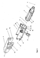
- the steering shaft 2 is rotatably supported in the adjusting part 4 about the axis 11 and is actuated by the steering wheel, not shown, by the driver.
- the adjusting part 4 is guided axially displaceably in the holding part 3.
- the holding part 3 is rotatably mounted in the retaining clip 5 about the pivot axis 21.
- the fixing device 6, which is designed here as a clamping system, comprising a control lever 10, a clamping bolt 9 and a counter-holder 20, a link plate 19 and a cam 18, the retaining clip 5, the holding part 3 and the adjusting part 4 are fixed in their movement against each other or released.
- the cam 18 is displaced in the link plate 19, so that the clamping bolt 9 is moved.
- the retaining clip 5 is attached to the vehicle with elements not shown here.
- the side cheeks 5a and 5b of the retaining clip 5 are relieved, so that the first and second surface portions are still in contact, but with only a small surface pressure, so that the adjusting member 4 relative to the holding part 3 slightly shifted can be.
- the steering column shown here can also be pivoted in the angular position.
- elongated holes 16 and 17 are provided in the side cheeks 5a and 5b.
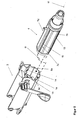
- the holding part 3 and the setting part 4 are designed such that only three pairs of first surface portions 7a, 7d, 7e of the holding part 3 and second surface portions 8a, 8d, 8e of the setting part 2 are pressed together.
- a slot 13 is provided.
- the holding part 3 as a sheet metal bending and - stamped part, possibly with corresponding embossing operations produced.
- the surface sections 8a and 8d are formed on two separate components which, like the side cheeks 3a and 3b, are penetrated by the clamping bolt 9.
- the holding part 3 does not completely surround the setting part 4 and has on its upper side an opening which extends along its longitudinal axis 12.
- the longitudinal axis 12 of the holding part 3 coincides with the axis 11 of the steering shaft 2.
- control part 4 and the retaining clip 5 is preferably produced in a sheet metal bending and stamping technology.
- the manufacturing tolerances of the actuating and holding parts can be compensated in a simple manner during assembly by the inserted corners, the surface portions 8a and 8d ( Fig. 3 ), are pressed in the pre-assembly at a predetermined setting of the fixing device with a predetermined force on the associated surface portions 7a and 7d and then with the part of the holding part, which carries the remaining surface portions 8c, 8e, 8b, are connected.
- the connection is then in the simplest case welding technology.
- the holding part 3 is thus composed of three individual parts and can be easily installed with the actuator 4 as an assembly in the steering column, as shown in the Fig. 2 is illustrated.
- FIG. 5 shows an alternative embodiment of the steering column, in which on some of the surface portions strip-like elevations are formed.
- strip-like elevations 15, which extend along the axis 11 of the steering shaft 2 are formed on the surface sections 7b and 7c of the actuating part 4.
- the actuator 4 was in FIG. 5 opposite to the illustration in FIG. 2 shown twisted about the axis 11 of the steering shaft 2.
- two parallel strip-like elevations 14 are formed on the surface portions 8a and 8d. However, these are aligned perpendicular to the axis 11 of the steering shaft 2.
- the setting member 4 is positioned according to the rotation and displacement shown in the dashed arrow lines in the holding part 3, so that in each case a strip-like increase cooperates with a substantially flat surface portion.
- surface portions may be convex.
- An example of this is in the FIG. 6 Far exaggerated.
- the corresponding surface portion is formed with a convexity K, which is elastically pressed when closing the fixing device.
- the holding part 3 is pushed with a bias in the direction of the steering shaft 2 on the adjusting part 4. This ensures a good guidance of the actuating part 4 even when the fixing device 6 is open.
Claims (15)
- Colonne de direction (1) pour un véhicule automobile, qui comprenda) un arbre de direction (2), qui est monté, en rotation autour de son axe (11), dans un organe de réglage (4),b) un étrier de retenue (5), qui, fixé au véhicule automobile, est destiné à maintenir la colonne de direction (1),c) une pièce de support (3) etd) un dispositif de fixation (6), dans l'état d'ouverture duquel l'organe de réglage (4) peut être déplacé par rapport à la pièce de support (3) pour le réglage de la position de la colonne de direction (1), au moins dans la direction axiale de l'arbre de direction (2), et dans l'état de fermeture duquel l'organe de réglage (4) est bloqué par rapport à la pièce de support (3), par le dispositif de fixation (6),e) la surface de l'organe de réglage (4), orientée à l'opposé de l'arbre de direction (2), présentant, dans la direction périphérique, plusieurs premières sections de surface planes (7a, 7b, 7c, 7d, 7e),f) et la surface de la pièce de retenue (3), qui, orientée vers l'arbre de direction (2), entoure, au moins partiellement, l'organe de réglage (4), présentant des deuxièmes sections de surface planes (8a, 8b,8c, 8d, 8e),g) les premières et les deuxièmes sections de surface s'étendant dans la direction de l'axe (11) de l'arbre de direction (2), et au moins trois paires de premières et de deuxièmes sections de surface planes (7a, 8a, 7b, 8b, 7c, 8c, 7d, 8d, 7e, 8e) pouvant, au moins partiellement, entrer en contact par adhérence ou par adhérence et engagement géométrique, pour la fixation de l'organe de réglage (4),h) et l'étrier de retenue (5) présentant des joues latérales (5a, 5b) peuvent être rapprochées l'une de l'autre serrées lors de la fermeture du dispositif de fixation (6) et peuvent ainsi serrer la pièce de retenue (3), caractérisée en ce quei) l'étrier de retenue (5) est un élément formé d'une pièce et que la pièce de support (3) est montée en pivotement autour d'un axe de pivotement (21) dans l'étrier de retenue (5).
- Colonne de direction selon la revendication 1, caractérisée en ce que l'axe de pivotement (21) traverse les joues latérales (5a, 5b).
- Colonne de direction selon l'une des revendications 1 ou 2, caractérisée en ce que, dans les joues latérales (5a, 5b), sont prévus des trous oblongs (16, 17), qui, vus dans la direction longitudinale de la colonne de direction, sont disposés à distance de l'axe de pivotement (21).
- Colonne de direction selon la revendication 3, caractérisée en ce que l'axe de pivotement (21) est disposé à l'une des extrémités de l'étrier de retenue (5) et que les trous oblongs (16, 17) sont disposés à l'autre extrémité de celui-ci.
- Colonne de direction selon l'une des revendications précédentes, caractérisée en ce qu'au moins l'une des premières et / ou l'une des deuxièmes sections de surface présentent au moins une saillie en forme de nervure (14, 15) pour la formation de points de pression discrets.
- Colonne de direction selon la revendication 5, caractérisée en ce qu'au moins une élévation en forme de nervure (14, 15) est orientée dans la direction de l'axe de l'arbre de direction (11).
- Colonne de direction selon revendication 5 ou 6, caractérisée en ce qu'au moins une élévation en forme de nervure (14, 15) est orientée perpendiculairement à l'axe de l'arbre de direction (11).
- Colonne de direction l'une des revendications précédentes, caractérisée en ce qu'au moins l'une des sections de surface (7a à 7e, 8a à 8e) est bombée de sorte qu'elle forme une convexité (K).
- Colonne de direction selon l'une des revendications précédentes, caractérisée en ce que le point le plus élevé de la convexité (K) dépasse au maximum de 0,05 mm une section de surface de référence plane imaginaire.
- Colonne de direction selon l'une des revendications précédentes, caractérisée en ce que la pièce de support (3) présente, le long de son axe longitudinal (12), une ouverture, qui peut être réduite lors de la fermeture du dispositif de fixation de sorte les sections ) de surface (7a à 7e, 8a à 8e) puissent être mises en contact les unes avec les autres par une pression en surface, nécessaire pour la fixation de l'élément de réglage (4) .
- Colonne de direction selon l'une ou plusieurs des revendications précédentes, caractérisée en ce qu'exactement quatre paires (7a, 8a, 7b, 8b, 7c, 8c, 7d, 8d) de premières et de deuxièmes sections de surface peuvent être mises en contact, au moins partiellement.
- Colonne de direction selon l'une des revendications précédentes, caractérisée en ce que l'étrier de retenue (5)) présente une section transversale en U.
- Colonne de direction selon l'une des revendications précédentes, caractérisée en ce que la pièce de support (3) peut être déplacée par rapport à l'étrier de retenue (5) quand le dispositif de fixation (6) est à l'état ouvert, et est fixée quand celui-ci est à l'état fermé.
- Colonne de direction selon l'une des revendications 10 à 13, caractérisée en ce que la pièce de support (3) est traversée par un boulon de serrage (9), qui est déplacé dans sa direction axiale, lors de l'ouverture et de la fermeture du dispositif de fixation (6), et qui élargit, respectivement réduit ainsi l'ouverture dans la pièce de support.
- Colonne de direction selon l'une des revendications précédentes, caractérisée en ce que l'étrier de retenue (5) est traversé par un boulon de serrage (9).
Priority Applications (1)
| Application Number | Priority Date | Filing Date | Title |
|---|---|---|---|
| PL06762687T PL1910148T5 (pl) | 2005-07-22 | 2006-07-19 | Przestawna kolumna kierownicy dla pojazdu mechanicznego |
Applications Claiming Priority (2)
| Application Number | Priority Date | Filing Date | Title |
|---|---|---|---|
| DE102005034952A DE102005034952B3 (de) | 2005-07-22 | 2005-07-22 | Verstellbare Lenksäule für ein Kraftfahrzeug |
| PCT/EP2006/007086 WO2007009760A1 (fr) | 2005-07-22 | 2006-07-19 | Colonne de direction reglable destinee a un vehicule |
Publications (3)
| Publication Number | Publication Date |
|---|---|
| EP1910148A1 EP1910148A1 (fr) | 2008-04-16 |
| EP1910148B1 true EP1910148B1 (fr) | 2010-12-29 |
| EP1910148B2 EP1910148B2 (fr) | 2015-06-10 |
Family
ID=36968907
Family Applications (1)
| Application Number | Title | Priority Date | Filing Date |
|---|---|---|---|
| EP06762687.9A Active EP1910148B2 (fr) | 2005-07-22 | 2006-07-19 | Colonne de direction reglable destinee a un vehicule |
Country Status (7)
| Country | Link |
|---|---|
| US (1) | US7918483B2 (fr) |
| EP (1) | EP1910148B2 (fr) |
| AT (1) | ATE493319T1 (fr) |
| DE (4) | DE102005034952B3 (fr) |
| ES (1) | ES2358750T5 (fr) |
| PL (1) | PL1910148T5 (fr) |
| WO (1) | WO2007009760A1 (fr) |
Cited By (2)
| Publication number | Priority date | Publication date | Assignee | Title |
|---|---|---|---|---|
| CN104540721A (zh) * | 2012-04-10 | 2015-04-22 | 蒂森克虏伯普利斯坦股份公司 | 纤维复合材料的轻量转向柱 |
| EP3075633A1 (fr) | 2015-03-31 | 2016-10-05 | FUJI KIKO Co., Ltd. | Dispositif de colonne de direction |
Families Citing this family (23)
| Publication number | Priority date | Publication date | Assignee | Title |
|---|---|---|---|---|
| EP2323947B1 (fr) | 2008-08-06 | 2019-07-03 | Life Technologies Corporation | Nanoparticules dispersables dans l'eau |
| DE202008017718U1 (de) | 2008-10-01 | 2010-07-15 | Thyssenkrupp Presta Ag | Von einem Wälzlager gelagerte Welle |
| DE102009051107B3 (de) * | 2009-10-28 | 2011-04-28 | Thyssenkrupp Presta Ag | Lager zur drehbaren Lagerung einer Lenkspindel |
| US9073567B2 (en) * | 2011-05-18 | 2015-07-07 | Nsk Ltd. | Steering apparatus for an automobile |
| DE102011056674B3 (de) | 2011-10-19 | 2012-12-06 | Thyssenkrupp Presta Aktiengesellschaft | Lenksäule für ein Kraftfahrzeug |
| DE102011054597A1 (de) * | 2011-10-19 | 2013-04-25 | Thyssenkrupp Presta Aktiengesellschaft | Lenkspindellagereinheit |
| DE102011054598B3 (de) | 2011-10-19 | 2013-01-17 | Thyssenkrupp Presta Ag | Lenkspindellagereinheit zur drehbaren Lagerung einer Lenkspindel |
| DE102011054606B3 (de) | 2011-10-19 | 2013-02-28 | Thyssenkrupp Presta Aktiengesellschaft | Lenkspindellagereinheit zur drehbaren Lagerung einer Lenkspindel |
| DE102013001442B3 (de) | 2013-01-29 | 2014-03-13 | Thyssenkrupp Presta Aktiengesellschaft | Lenksäule in Faserverbundtechnologie, basierend auf Pultrusion- und Flecht- und/oder Wickeltechnologie |
| GB2511565B (en) * | 2013-03-08 | 2015-04-01 | Nsk Deutschland Gmbh | Apparatus and method for a steering column |
| AT514088B1 (de) * | 2013-06-20 | 2014-10-15 | Thyssenkrupp Presta Ag | Lenksäule für ein Kraftfahrzeug und Verfahren zur Herstellung einer Lenksäule |
| DE102013021201A1 (de) | 2013-12-17 | 2015-06-18 | Daimler Ag | Lenksäule für einen Kraftwagen |
| JP6192565B2 (ja) | 2014-02-21 | 2017-09-06 | 富士機工株式会社 | ステアリングコラム装置 |
| DE102015216348A1 (de) * | 2015-08-26 | 2017-03-02 | Thyssenkrupp Ag | Klemmvorrichtung einer verstellbaren Lenksäule für Kraftfahrzeuge |
| DE102015216715A1 (de) | 2015-09-01 | 2017-03-02 | Thyssenkrupp Ag | Verstellbare Lenksäule für Kraftfahrzeuge mit Energieabsorber für den Fahrzeugcrash |
| DE102015217761B3 (de) | 2015-09-16 | 2016-10-13 | Thyssenkrupp Ag | Lenksäule für Kraftfahrzeuge mit Energieabsorber für den Crashfall |
| DE102015225488B3 (de) | 2015-12-16 | 2016-12-22 | Thyssenkrupp Ag | Verstellbare Lenksäule für Kraftfahrzeuge mit Energieabsorptionsvorrichtung |
| CN108602524B (zh) * | 2016-02-04 | 2021-02-02 | 日本精工株式会社 | 转向装置 |
| JP6621359B2 (ja) * | 2016-03-31 | 2019-12-18 | 富士機工株式会社 | ステアリングコラム装置 |
| DE102016220140A1 (de) * | 2016-10-14 | 2018-04-19 | Thyssenkrupp Ag | Lenksäule für ein Kraftfahrzeug und Verfahren zum Herstellen einer Lenksäule |
| FR3075744B1 (fr) * | 2017-12-27 | 2020-12-04 | Robert Bosch Automotive Steering Vendome | Colonne de direction |
| CN114650942A (zh) * | 2019-11-22 | 2022-06-21 | 罗伯特博世汽车转向旺多姆公司 | 用于调节抵抗两个套叠元件之间的相对平移运动的阻力的调节系统 |
| DE102020201058A1 (de) * | 2020-01-29 | 2021-07-29 | Thyssenkrupp Ag | Lenksäule für ein Kraftfahrzeug |
Family Cites Families (37)
| Publication number | Priority date | Publication date | Assignee | Title |
|---|---|---|---|---|
| US3877670A (en) * | 1973-04-18 | 1975-04-15 | Scott & Fetzer Co | Extensible support structure |
| IT1091449B (it) * | 1977-11-09 | 1985-07-06 | Fiat Veicoli Ind | Dispositivo per la registrazione dell assetto volante sterzo di autoveicoli |
| ES494694A0 (es) * | 1980-07-30 | 1981-04-01 | Bendiberica Sa | Perfeccionamientos en mecanismos de ajuste de la posicion del volante de direccion en vehiculos |
| GB2116496B (en) | 1982-03-09 | 1985-08-14 | Gen Motors Ltd | Steering column mounting assemblies |
| SE8803943D0 (sv) * | 1988-10-31 | 1988-10-31 | Ffv Autotech Ab | Rattstaangsfaeste med glid- och tippfunktion |
| US5009121A (en) * | 1989-07-07 | 1991-04-23 | Nippon Seiko Kabushiki Kaisha | Telescopic steering column device |
| DE4103548C1 (fr) * | 1991-02-06 | 1992-04-23 | Mercedes-Benz Aktiengesellschaft, 7000 Stuttgart, De | |
| GB2259132A (en) * | 1991-08-27 | 1993-03-03 | Torrington Co | Locking device for adjustable steering column. |
| GB2273338A (en) * | 1992-12-02 | 1994-06-15 | Torrington Co | Steering column clamping mechanism. |
| FR2701682B1 (fr) * | 1993-02-17 | 1995-05-24 | Peugeot | Ensemble de colonne de direction escamotable en cas de choc. |
| FR2714647B1 (fr) | 1994-01-06 | 1996-03-15 | Nacam | Dispositif de maintien pour colonne de direction de véhicule automobile. |
| US5722299A (en) * | 1994-06-30 | 1998-03-03 | Fuji Kiko Co., Ltd. | Adjustable steering column assembly for a vehicle |
| JP3415953B2 (ja) * | 1995-02-03 | 2003-06-09 | 日本精工株式会社 | ステアリングコラムの支持装置 |
| US5788277A (en) * | 1995-03-30 | 1998-08-04 | Nsk Ltd. | Tilt type steering apparatus |
| US5678454A (en) * | 1995-06-15 | 1997-10-21 | Trw Inc. | Steering column |
| GB9704808D0 (en) † | 1997-03-07 | 1997-04-23 | Lucas Ind Plc | Improvements relating to steering assemblies |
| GB9716747D0 (en) * | 1997-08-08 | 1997-10-15 | Lucas Ind Plc | Improvements relating to steering assemblies |
| US6036228A (en) * | 1998-05-04 | 2000-03-14 | General Motors Corporation | Adjustable steering column for motor vehicle |
| US5988010A (en) * | 1998-05-04 | 1999-11-23 | General Motors Corporation | Adjustable steering column for motor vehicle |
| FR2778704B1 (fr) | 1998-05-12 | 2000-07-21 | Lemforder Nacam Sa | Dispositif de serrage d'un systeme de reglage en position d'un element par rapport a un autre element |
| JP2000118415A (ja) * | 1998-10-09 | 2000-04-25 | Fuji Kiko Co Ltd | ステアリングコラム |
| US6139057A (en) * | 1999-02-04 | 2000-10-31 | Delphi Technologies, Inc. | Position control apparatus for steering column |
| DE60133331T3 (de) * | 2000-02-15 | 2012-12-06 | Nsk Ltd. | Lenkung für ein Automobil |
| US6357318B1 (en) * | 2000-06-16 | 2002-03-19 | Trw Inc. | Steering column |
| US6357317B1 (en) † | 2000-06-16 | 2002-03-19 | Trw Inc. | Steering column |
| FR2818602B1 (fr) * | 2000-12-26 | 2003-03-28 | Nacam | Dispositif de serrage d'un element reglable par rapport a un ensemble support |
| JP3886766B2 (ja) * | 2001-01-11 | 2007-02-28 | 富士機工株式会社 | チルト・テレスコピック式ステアリングコラム装置 |
| JP3933409B2 (ja) † | 2001-03-29 | 2007-06-20 | 株式会社ジェイテクト | 舵取装置 |
| US6957595B2 (en) * | 2001-07-13 | 2005-10-25 | Deere & Co. | Tilt steering wheel mechanism |
| JP2003118595A (ja) * | 2001-08-06 | 2003-04-23 | Nsk Ltd | 車両用ステアリング装置及びその製造方法 |
| JP2003127874A (ja) * | 2001-10-23 | 2003-05-08 | Fuji Kiko Co Ltd | 衝撃吸収式チルトステアリングコラム |
| JP4147579B2 (ja) | 2002-01-17 | 2008-09-10 | 日本精工株式会社 | ステアリング装置 |
| US6666478B2 (en) * | 2002-05-01 | 2003-12-23 | Trw Inc. | Steering column |
| AU2003227417A1 (en) * | 2002-05-10 | 2003-11-11 | Nsk Ltd. | Steering device |
| DE10232041A1 (de) † | 2002-07-16 | 2004-02-05 | Thyssenkrupp Presta Ag | Lenksäule |
| WO2004086225A1 (fr) | 2003-03-24 | 2004-10-07 | Fujitsu Limited | Systeme informatique virtuel |
| JP4541297B2 (ja) * | 2003-03-26 | 2010-09-08 | 日本精工株式会社 | 車両用ステアリング装置 |
-
2005
- 2005-07-22 DE DE102005034952A patent/DE102005034952B3/de not_active Expired - Fee Related
-
2006
- 2006-07-19 WO PCT/EP2006/007086 patent/WO2007009760A1/fr active Application Filing
- 2006-07-19 PL PL06762687T patent/PL1910148T5/pl unknown
- 2006-07-19 ES ES06762687.9T patent/ES2358750T5/es active Active
- 2006-07-19 US US11/996,150 patent/US7918483B2/en active Active
- 2006-07-19 DE DE202006021160U patent/DE202006021160U1/de not_active Expired - Lifetime
- 2006-07-19 DE DE202006021191U patent/DE202006021191U1/de not_active Expired - Lifetime
- 2006-07-19 DE DE502006008616T patent/DE502006008616D1/de active Active
- 2006-07-19 AT AT06762687T patent/ATE493319T1/de active
- 2006-07-19 EP EP06762687.9A patent/EP1910148B2/fr active Active
Cited By (3)
| Publication number | Priority date | Publication date | Assignee | Title |
|---|---|---|---|---|
| CN104540721A (zh) * | 2012-04-10 | 2015-04-22 | 蒂森克虏伯普利斯坦股份公司 | 纤维复合材料的轻量转向柱 |
| EP3075633A1 (fr) | 2015-03-31 | 2016-10-05 | FUJI KIKO Co., Ltd. | Dispositif de colonne de direction |
| US9505426B2 (en) | 2015-03-31 | 2016-11-29 | Fuji Kiko Co., Ltd. | Steering column device |
Also Published As
| Publication number | Publication date |
|---|---|
| DE202006021191U1 (de) | 2013-07-01 |
| ATE493319T1 (de) | 2011-01-15 |
| EP1910148A1 (fr) | 2008-04-16 |
| DE102005034952B3 (de) | 2007-02-22 |
| PL1910148T3 (pl) | 2011-05-31 |
| ES2358750T5 (es) | 2015-09-21 |
| DE502006008616D1 (de) | 2011-02-10 |
| ES2358750T3 (es) | 2011-05-13 |
| US20080290641A1 (en) | 2008-11-27 |
| US7918483B2 (en) | 2011-04-05 |
| DE202006021160U1 (de) | 2013-03-27 |
| WO2007009760A1 (fr) | 2007-01-25 |
| EP1910148B2 (fr) | 2015-06-10 |
| PL1910148T5 (pl) | 2016-08-31 |
Similar Documents
| Publication | Publication Date | Title |
|---|---|---|
| EP1910148B1 (fr) | Colonne de direction reglable destinee a un vehicule | |
| EP1957341B1 (fr) | Colonne de direction réglable conçue pour un vehicule automobile | |
| EP2398688B1 (fr) | Colonne de direction pour un véhicule | |
| EP2928754B1 (fr) | Colonne de direction pour véhicule à moteur | |
| EP2512899B1 (fr) | Colonne de direction pour un véhicule à moteur | |
| EP2307259B1 (fr) | Colonne de direction pour un véhicule motorisé | |
| EP1590226B1 (fr) | Dispositif de serrage pour colonne de direction | |
| DE102005035009B3 (de) | Verstellbare Lenksäule für ein Kraftfahrzeug | |
| DE10145896B4 (de) | Verschiebeeinrichtung für eine Fahrzeuglenksäule | |
| DE102011000319B3 (de) | Feststelleinrichtung zum Feststellen einer Lenkspindellagereinheit | |
| DE102009038317B4 (de) | Verstellbare Lenksäule für ein Kraftfahrzeug | |
| EP2900540B1 (fr) | Colonne de direction pour véhicule automobile | |
| EP2981447A1 (fr) | Procédé de fabrication d'un bloc palier d'arbre de direction | |
| EP3297889B1 (fr) | Colonne de direction d'un véhicule automobile et dispositif d'absorption d'énergie | |
| WO2013056766A1 (fr) | Colonne de direction pour véhicule à moteur | |
| WO2007101565A1 (fr) | Arrangement de colonne de direction pour véhicules automobiles | |
| WO2020144172A1 (fr) | Colonne de direction pour un véhicule automobile | |
| WO2007003258A1 (fr) | Dispositif de serrage pour colonne de direction | |
| EP3515790B1 (fr) | Ensemble jupe conçu pour une colonne de direction réglable d'un véhicule automobile | |
| EP3911553B1 (fr) | Colonne de direction pour un véhicule automobile | |
| EP3987199B1 (fr) | Élément d'accouplement à monter sur une barre filetée, système avec une barre filetée et un élément d'accouplement, entraînement à broche et colonne de direction | |
| DE102014108321A1 (de) | Lenksäule für ein Kraftfahrzeug |
Legal Events
| Date | Code | Title | Description |
|---|---|---|---|
| PUAI | Public reference made under article 153(3) epc to a published international application that has entered the european phase |
Free format text: ORIGINAL CODE: 0009012 |
|
| 17P | Request for examination filed |
Effective date: 20080222 |
|
| AK | Designated contracting states |
Kind code of ref document: A1 Designated state(s): AT BE BG CH CY CZ DE DK EE ES FI FR GB GR HU IE IS IT LI LT LU LV MC NL PL PT RO SE SI SK TR |
|
| RIN1 | Information on inventor provided before grant (corrected) |
Inventor name: SCHOLTEN, MICHAEL Inventor name: GALEHR, ROBERT |
|
| 17Q | First examination report despatched |
Effective date: 20090929 |
|
| GRAP | Despatch of communication of intention to grant a patent |
Free format text: ORIGINAL CODE: EPIDOSNIGR1 |
|
| GRAS | Grant fee paid |
Free format text: ORIGINAL CODE: EPIDOSNIGR3 |
|
| GRAA | (expected) grant |
Free format text: ORIGINAL CODE: 0009210 |
|
| AK | Designated contracting states |
Kind code of ref document: B1 Designated state(s): AT BE BG CH CY CZ DE DK EE ES FI FR GB GR HU IE IS IT LI LT LU LV MC NL PL PT RO SE SI SK TR |
|
| REG | Reference to a national code |
Ref country code: GB Ref legal event code: FG4D Free format text: NOT ENGLISH |
|
| REG | Reference to a national code |
Ref country code: CH Ref legal event code: EP |
|
| REG | Reference to a national code |
Ref country code: IE Ref legal event code: FG4D Free format text: LANGUAGE OF EP DOCUMENT: GERMAN |
|
| REF | Corresponds to: |
Ref document number: 502006008616 Country of ref document: DE Date of ref document: 20110210 Kind code of ref document: P |
|
| REG | Reference to a national code |
Ref country code: DE Ref legal event code: R096 Ref document number: 502006008616 Country of ref document: DE Effective date: 20110210 |
|
| REG | Reference to a national code |
Ref country code: NL Ref legal event code: VDEP Effective date: 20101229 |
|
| PG25 | Lapsed in a contracting state [announced via postgrant information from national office to epo] |
Ref country code: LT Free format text: LAPSE BECAUSE OF FAILURE TO SUBMIT A TRANSLATION OF THE DESCRIPTION OR TO PAY THE FEE WITHIN THE PRESCRIBED TIME-LIMIT Effective date: 20101229 |
|
| REG | Reference to a national code |
Ref country code: ES Ref legal event code: FG2A Ref document number: 2358750 Country of ref document: ES Kind code of ref document: T3 Effective date: 20110503 |
|
| LTIE | Lt: invalidation of european patent or patent extension |
Effective date: 20101229 |
|
| PG25 | Lapsed in a contracting state [announced via postgrant information from national office to epo] |
Ref country code: BG Free format text: LAPSE BECAUSE OF FAILURE TO SUBMIT A TRANSLATION OF THE DESCRIPTION OR TO PAY THE FEE WITHIN THE PRESCRIBED TIME-LIMIT Effective date: 20110329 Ref country code: LV Free format text: LAPSE BECAUSE OF FAILURE TO SUBMIT A TRANSLATION OF THE DESCRIPTION OR TO PAY THE FEE WITHIN THE PRESCRIBED TIME-LIMIT Effective date: 20101229 Ref country code: SE Free format text: LAPSE BECAUSE OF FAILURE TO SUBMIT A TRANSLATION OF THE DESCRIPTION OR TO PAY THE FEE WITHIN THE PRESCRIBED TIME-LIMIT Effective date: 20101229 Ref country code: CY Free format text: LAPSE BECAUSE OF FAILURE TO SUBMIT A TRANSLATION OF THE DESCRIPTION OR TO PAY THE FEE WITHIN THE PRESCRIBED TIME-LIMIT Effective date: 20101229 Ref country code: FI Free format text: LAPSE BECAUSE OF FAILURE TO SUBMIT A TRANSLATION OF THE DESCRIPTION OR TO PAY THE FEE WITHIN THE PRESCRIBED TIME-LIMIT Effective date: 20101229 Ref country code: SI Free format text: LAPSE BECAUSE OF FAILURE TO SUBMIT A TRANSLATION OF THE DESCRIPTION OR TO PAY THE FEE WITHIN THE PRESCRIBED TIME-LIMIT Effective date: 20101229 |
|
| REG | Reference to a national code |
Ref country code: PL Ref legal event code: T3 |
|
| REG | Reference to a national code |
Ref country code: IE Ref legal event code: FD4D |
|
| PG25 | Lapsed in a contracting state [announced via postgrant information from national office to epo] |
Ref country code: GR Free format text: LAPSE BECAUSE OF FAILURE TO SUBMIT A TRANSLATION OF THE DESCRIPTION OR TO PAY THE FEE WITHIN THE PRESCRIBED TIME-LIMIT Effective date: 20110330 Ref country code: PT Free format text: LAPSE BECAUSE OF FAILURE TO SUBMIT A TRANSLATION OF THE DESCRIPTION OR TO PAY THE FEE WITHIN THE PRESCRIBED TIME-LIMIT Effective date: 20110429 Ref country code: EE Free format text: LAPSE BECAUSE OF FAILURE TO SUBMIT A TRANSLATION OF THE DESCRIPTION OR TO PAY THE FEE WITHIN THE PRESCRIBED TIME-LIMIT Effective date: 20101229 Ref country code: IS Free format text: LAPSE BECAUSE OF FAILURE TO SUBMIT A TRANSLATION OF THE DESCRIPTION OR TO PAY THE FEE WITHIN THE PRESCRIBED TIME-LIMIT Effective date: 20110429 |
|
| PG25 | Lapsed in a contracting state [announced via postgrant information from national office to epo] |
Ref country code: RO Free format text: LAPSE BECAUSE OF FAILURE TO SUBMIT A TRANSLATION OF THE DESCRIPTION OR TO PAY THE FEE WITHIN THE PRESCRIBED TIME-LIMIT Effective date: 20101229 Ref country code: SK Free format text: LAPSE BECAUSE OF FAILURE TO SUBMIT A TRANSLATION OF THE DESCRIPTION OR TO PAY THE FEE WITHIN THE PRESCRIBED TIME-LIMIT Effective date: 20101229 Ref country code: NL Free format text: LAPSE BECAUSE OF FAILURE TO SUBMIT A TRANSLATION OF THE DESCRIPTION OR TO PAY THE FEE WITHIN THE PRESCRIBED TIME-LIMIT Effective date: 20101229 |
|
| PLBI | Opposition filed |
Free format text: ORIGINAL CODE: 0009260 |
|
| PG25 | Lapsed in a contracting state [announced via postgrant information from national office to epo] |
Ref country code: IE Free format text: LAPSE BECAUSE OF FAILURE TO SUBMIT A TRANSLATION OF THE DESCRIPTION OR TO PAY THE FEE WITHIN THE PRESCRIBED TIME-LIMIT Effective date: 20101229 Ref country code: DK Free format text: LAPSE BECAUSE OF FAILURE TO SUBMIT A TRANSLATION OF THE DESCRIPTION OR TO PAY THE FEE WITHIN THE PRESCRIBED TIME-LIMIT Effective date: 20101229 |
|
| PLAX | Notice of opposition and request to file observation + time limit sent |
Free format text: ORIGINAL CODE: EPIDOSNOBS2 |
|
| 26 | Opposition filed |
Opponent name: ZF SYSTEMES DE DIRECTION NACAM, S.A.S. Effective date: 20110929 |
|
| REG | Reference to a national code |
Ref country code: DE Ref legal event code: R026 Ref document number: 502006008616 Country of ref document: DE Effective date: 20110929 |
|
| BERE | Be: lapsed |
Owner name: THYSSENKRUPP PRESTA AKTIENGESELLSCHAFT Effective date: 20110731 |
|
| PG25 | Lapsed in a contracting state [announced via postgrant information from national office to epo] |
Ref country code: MC Free format text: LAPSE BECAUSE OF NON-PAYMENT OF DUE FEES Effective date: 20110731 |
|
| PLAF | Information modified related to communication of a notice of opposition and request to file observations + time limit |
Free format text: ORIGINAL CODE: EPIDOSCOBS2 |
|
| PG25 | Lapsed in a contracting state [announced via postgrant information from national office to epo] |
Ref country code: BE Free format text: LAPSE BECAUSE OF NON-PAYMENT OF DUE FEES Effective date: 20110731 |
|
| PLBB | Reply of patent proprietor to notice(s) of opposition received |
Free format text: ORIGINAL CODE: EPIDOSNOBS3 |
|
| REG | Reference to a national code |
Ref country code: AT Ref legal event code: MM01 Ref document number: 493319 Country of ref document: AT Kind code of ref document: T Effective date: 20110719 |
|
| PG25 | Lapsed in a contracting state [announced via postgrant information from national office to epo] |
Ref country code: AT Free format text: LAPSE BECAUSE OF NON-PAYMENT OF DUE FEES Effective date: 20110719 |
|
| PG25 | Lapsed in a contracting state [announced via postgrant information from national office to epo] |
Ref country code: LU Free format text: LAPSE BECAUSE OF NON-PAYMENT OF DUE FEES Effective date: 20110719 |
|
| APBM | Appeal reference recorded |
Free format text: ORIGINAL CODE: EPIDOSNREFNO |
|
| APBP | Date of receipt of notice of appeal recorded |
Free format text: ORIGINAL CODE: EPIDOSNNOA2O |
|
| APAH | Appeal reference modified |
Free format text: ORIGINAL CODE: EPIDOSCREFNO |
|
| APBM | Appeal reference recorded |
Free format text: ORIGINAL CODE: EPIDOSNREFNO |
|
| APBP | Date of receipt of notice of appeal recorded |
Free format text: ORIGINAL CODE: EPIDOSNNOA2O |
|
| APBQ | Date of receipt of statement of grounds of appeal recorded |
Free format text: ORIGINAL CODE: EPIDOSNNOA3O |
|
| APBQ | Date of receipt of statement of grounds of appeal recorded |
Free format text: ORIGINAL CODE: EPIDOSNNOA3O |
|
| PG25 | Lapsed in a contracting state [announced via postgrant information from national office to epo] |
Ref country code: TR Free format text: LAPSE BECAUSE OF FAILURE TO SUBMIT A TRANSLATION OF THE DESCRIPTION OR TO PAY THE FEE WITHIN THE PRESCRIBED TIME-LIMIT Effective date: 20101229 |
|
| PG25 | Lapsed in a contracting state [announced via postgrant information from national office to epo] |
Ref country code: HU Free format text: LAPSE BECAUSE OF FAILURE TO SUBMIT A TRANSLATION OF THE DESCRIPTION OR TO PAY THE FEE WITHIN THE PRESCRIBED TIME-LIMIT Effective date: 20101229 |
|
| PGFP | Annual fee paid to national office [announced via postgrant information from national office to epo] |
Ref country code: CH Payment date: 20130805 Year of fee payment: 8 |
|
| APBU | Appeal procedure closed |
Free format text: ORIGINAL CODE: EPIDOSNNOA9O |
|
| REG | Reference to a national code |
Ref country code: CH Ref legal event code: PL |
|
| PG25 | Lapsed in a contracting state [announced via postgrant information from national office to epo] |
Ref country code: LI Free format text: LAPSE BECAUSE OF NON-PAYMENT OF DUE FEES Effective date: 20140731 Ref country code: CH Free format text: LAPSE BECAUSE OF NON-PAYMENT OF DUE FEES Effective date: 20140731 |
|
| PUAH | Patent maintained in amended form |
Free format text: ORIGINAL CODE: 0009272 |
|
| STAA | Information on the status of an ep patent application or granted ep patent |
Free format text: STATUS: PATENT MAINTAINED AS AMENDED |
|
| 27A | Patent maintained in amended form |
Effective date: 20150610 |
|
| AK | Designated contracting states |
Kind code of ref document: B2 Designated state(s): AT BE BG CH CY CZ DE DK EE ES FI FR GB GR HU IE IS IT LI LT LU LV MC NL PL PT RO SE SI SK TR |
|
| REG | Reference to a national code |
Ref country code: DE Ref legal event code: R102 Ref document number: 502006008616 Country of ref document: DE |
|
| REG | Reference to a national code |
Ref country code: ES Ref legal event code: DC2A Ref document number: 2358750 Country of ref document: ES Kind code of ref document: T5 Effective date: 20150921 |
|
| REG | Reference to a national code |
Ref country code: FR Ref legal event code: PLFP Year of fee payment: 11 |
|
| REG | Reference to a national code |
Ref country code: FR Ref legal event code: PLFP Year of fee payment: 12 |
|
| REG | Reference to a national code |
Ref country code: FR Ref legal event code: PLFP Year of fee payment: 13 |
|
| REG | Reference to a national code |
Ref country code: DE Ref legal event code: R081 Ref document number: 502006008616 Country of ref document: DE Owner name: THYSSENKRUPP PRESTA AKTIENGESELLSCHAFT, LI Free format text: FORMER OWNER: THYSSENKRUPP PRESTA AKTIENGESELLSCHAFT, ESCHEN, LI |
|
| REG | Reference to a national code |
Ref country code: DE Ref legal event code: R084 Ref document number: 502006008616 Country of ref document: DE |
|
| PGFP | Annual fee paid to national office [announced via postgrant information from national office to epo] |
Ref country code: IT Payment date: 20220726 Year of fee payment: 17 Ref country code: ES Payment date: 20220921 Year of fee payment: 17 Ref country code: CZ Payment date: 20220718 Year of fee payment: 17 |
|
| PGFP | Annual fee paid to national office [announced via postgrant information from national office to epo] |
Ref country code: PL Payment date: 20220707 Year of fee payment: 17 |
|
| PGFP | Annual fee paid to national office [announced via postgrant information from national office to epo] |
Ref country code: GB Payment date: 20230720 Year of fee payment: 18 |
|
| PGFP | Annual fee paid to national office [announced via postgrant information from national office to epo] |
Ref country code: FR Payment date: 20230725 Year of fee payment: 18 Ref country code: DE Payment date: 20230719 Year of fee payment: 18 |