EP1910148B1 - Adjustable steering column for a motor vehicle - Google Patents
Adjustable steering column for a motor vehicle Download PDFInfo
- Publication number
- EP1910148B1 EP1910148B1 EP06762687A EP06762687A EP1910148B1 EP 1910148 B1 EP1910148 B1 EP 1910148B1 EP 06762687 A EP06762687 A EP 06762687A EP 06762687 A EP06762687 A EP 06762687A EP 1910148 B1 EP1910148 B1 EP 1910148B1
- Authority
- EP
- European Patent Office
- Prior art keywords
- steering column
- holding
- holding part
- fixing device
- steering
- Prior art date
- Legal status (The legal status is an assumption and is not a legal conclusion. Google has not performed a legal analysis and makes no representation as to the accuracy of the status listed.)
- Active
Links
- 230000003247 decreasing effect Effects 0.000 claims 2
- 230000002093 peripheral effect Effects 0.000 claims 1
- 238000006073 displacement reaction Methods 0.000 description 9
- 238000004519 manufacturing process Methods 0.000 description 7
- 239000002184 metal Substances 0.000 description 5
- 238000005452 bending Methods 0.000 description 4
- 238000013461 design Methods 0.000 description 3
- 238000010276 construction Methods 0.000 description 2
- 238000011161 development Methods 0.000 description 2
- 230000005489 elastic deformation Effects 0.000 description 2
- 238000005516 engineering process Methods 0.000 description 2
- 238000004080 punching Methods 0.000 description 2
- 238000010521 absorption reaction Methods 0.000 description 1
- 230000005540 biological transmission Effects 0.000 description 1
- 238000005352 clarification Methods 0.000 description 1
- 230000007423 decrease Effects 0.000 description 1
- 230000001419 dependent effect Effects 0.000 description 1
- 238000004049 embossing Methods 0.000 description 1
- 239000000463 material Substances 0.000 description 1
- 238000000034 method Methods 0.000 description 1
- 238000004806 packaging method and process Methods 0.000 description 1
- 230000002265 prevention Effects 0.000 description 1
- 238000012545 processing Methods 0.000 description 1
- 230000000452 restraining effect Effects 0.000 description 1
- 238000005096 rolling process Methods 0.000 description 1
- 238000012360 testing method Methods 0.000 description 1
- 238000003466 welding Methods 0.000 description 1
Images


Classifications
-
- B—PERFORMING OPERATIONS; TRANSPORTING
- B62—LAND VEHICLES FOR TRAVELLING OTHERWISE THAN ON RAILS
- B62D—MOTOR VEHICLES; TRAILERS
- B62D1/00—Steering controls, i.e. means for initiating a change of direction of the vehicle
- B62D1/02—Steering controls, i.e. means for initiating a change of direction of the vehicle vehicle-mounted
- B62D1/16—Steering columns
- B62D1/18—Steering columns yieldable or adjustable, e.g. tiltable
- B62D1/184—Mechanisms for locking columns at selected positions
Definitions
- the invention relates to an adjustable steering column for a motor vehicle, comprising a steering shaft which is rotatably mounted in an actuating part, a holding part and a fixing device, in the open state, the adjusting member relative to the holding part for adjusting the position of the steering column is adjustable at least in the axial direction of the steering shaft and in the closed state, the setting part of the fixing device relative to the holding part is detected.
- Adjustable steering columns are used to increase the comfort of the driver and can be changed in their length, height and / or angular position, so as to be able to adjust the position of the steering wheel to the driver's seating position.
- these steering columns have an actuating part whose position is variable with respect to a holding part and can be fixed with a fixing device or a clamping system.
- a fixing device in which the left and right two side cheeks are formed on the holding part, between which the actuating part is clamped. By adjusting a clamping axis, the side cheeks are compressed for the closing of the fixing, so that a corresponding holding force is applied.
- the number of individual parts and processing steps is correspondingly high.
- the support of the actuator against rotation about the clamping axis is not very stiff.
- a fixing device for the casing pipe of a vehicle steering column consisting of a U-shaped support with two downwardly directed legs, a jacket tube partially surrounding axially slotted resilient sleeve and a U-shaped clamping piece of sheet metal between the sleeve and the legs of the support ,
- adjustable steering columns both in terms of their length and in terms their inclination angle are adjustable.
- the steering column via two separate, spaced-apart retaining clips is connected to the vehicle body.
- One of the two retaining clips also serves as a receptacle of the pivot axis about which the steering column can be pivoted.
- a disadvantage of this construction is that two separate components, namely the separate retaining clips 2 and 4, are required to secure the steering column to the vehicle body, and that these retaining clips must be connected to the vehicle body at two separate, spaced-apart attachment points ,
- the object of the invention is a fixing device for an adjustable in length, that is in the axial direction of the steering shaft, and in terms of its inclination angle steering column provide; the high holding forces in the closed state at least in this axial direction against an adjustment of the adjusting member relative to the holding part applies, wherein the actuating travel and actuating forces on the adjusting lever correspond to the comfort requirements of the driver.
- a steering column of the aforementioned type is proposed for this purpose, in which the direction away from the steering shaft surface of the actuator in the circumferential direction has a plurality of first surface portions, the steering spindle directed towards the surface of the holding part, which surrounds the actuating part at least partially, second surface portions, wherein the first and second surface portions extend in the direction of the axis of the steering spindle and at least three pairs of first and second surface portions are at least partially in non-positive or frictional and positive contact brought to fix the adjusting part.
- the actuating part with the retaining part is secured non-positively against displacement in the direction of the axis of the steering spindle.
- the contact causes even at low normal forces or surface pressures a high rigidity of the arrangement and high holding forces against displacement of the actuating part relative to the holding part.
- the surfaces serve as guides, so that the control part can be easily adjusted relative to the holding part by the driver.
- the steering column can be pivoted in the angular position.
- slots are provided at a distance from the pivot axis, which are provided in side cheeks of the retaining clip and by the fixing device, which includes, for example, a clamping bolt, are penetrated.
- the slots may be both straight and have a curved circular section shape, the center of which lies on the pivot axis.
- the pivot axis at one end and the slots and the fixing device at the other end of the retaining clip are arranged.
- particularly high forces can be supported on the steering wheel facing the end of the steering shaft at a certain fixing force of the fixing device.
- the holding part has an opening along its longitudinal axis, which can be reduced when the fixing device is closed, so that the first and second surface sections can be brought into contact with the adjusting part or holding part with a surface pressure required for fixing the setting part, wherein at least one of the in Contact brought surface sections is almost flat.
- the solution according to the invention consists in generating as many friction forces as possible on the circumference of the setting part by means of two large area contacts which lead to high displacement forces in the closed state of the fixing device and at the same time to ensure guidance in the opened state of the fixing device. Furthermore, a support should be made in as many directions as possible in order to increase the rigidity and reduce the tendency to oscillate. About the design of the surface pairings and corresponding surface pressures, the displacement forces and the holding forces can be adjusted. Therefore, flat surface sections are preferred.
- Such an actuating part and such a holding part can be produced, for example, in a simple manner by a sheet metal bending and punching operation and thereby the surface portions are formed almost flat. Since the material experiences only little elongation during bending and punching operations, there are production-related restrictions in the precision of the flatness of the surfaces thus formed. As tests have shown, but these accuracies are sufficient to achieve sufficiently high resistance forces against displacement of the actuating part relative to the holding part.
- At least one of the first and / or second surface portions to form discrete pressure points has at least one strip-like increase.
- the power transmission takes place via the contact, which forms between the strip-like elevation and the opposite surface portion.
- the demands on the manufacturing accuracy are lowered.
- Low fit inaccuracies can be compensated by elastic springback in the surface sections.
- at least one strip-like elevation in the direction of the axis of the steering spindle is preferably aligned.
- at least one strip-like elevation is provided, preferably at another surface portion, which is aligned perpendicular to the axis of the steering shaft. More preferably, two such elevations are arranged one behind the other in the adjustment direction.
- the surface contacts are still increased by a slight crowning of almost flat surfaces, so when closing the fixing initially the convex protruding from the surface portions of the first and / or second surface portions come into contact and forms a large area surface contact during the process of closing under elastic deformation.
- the internal stresses are favorably increased, so that the rigidity of the steering column is further increased.
- Convexities ie elevations of the center of area with respect to the edge of the nearly flat surface of up to 0.05 mm, have proved to be useful and useful. If the convexities are too big, it may the large-area contact no longer produce by simple elastic deformation, so that the rigidity of the arrangement decreases again.
- the steering shaft 2 is rotatably supported in the adjusting part 4 about the axis 11 and is actuated by the steering wheel, not shown, by the driver.
- the adjusting part 4 is guided axially displaceably in the holding part 3.
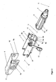
- the holding part 3 is rotatably mounted in the retaining clip 5 about the pivot axis 21.
- the fixing device 6, which is designed here as a clamping system, comprising a control lever 10, a clamping bolt 9 and a counter-holder 20, a link plate 19 and a cam 18, the retaining clip 5, the holding part 3 and the adjusting part 4 are fixed in their movement against each other or released.
- the cam 18 is displaced in the link plate 19, so that the clamping bolt 9 is moved.
- the retaining clip 5 is attached to the vehicle with elements not shown here.
- the side cheeks 5a and 5b of the retaining clip 5 are relieved, so that the first and second surface portions are still in contact, but with only a small surface pressure, so that the adjusting member 4 relative to the holding part 3 slightly shifted can be.
- the steering column shown here can also be pivoted in the angular position.
- elongated holes 16 and 17 are provided in the side cheeks 5a and 5b.
- the holding part 3 and the setting part 4 are designed such that only three pairs of first surface portions 7a, 7d, 7e of the holding part 3 and second surface portions 8a, 8d, 8e of the setting part 2 are pressed together.
- a slot 13 is provided.
- the holding part 3 as a sheet metal bending and - stamped part, possibly with corresponding embossing operations produced.
- the surface sections 8a and 8d are formed on two separate components which, like the side cheeks 3a and 3b, are penetrated by the clamping bolt 9.
- the holding part 3 does not completely surround the setting part 4 and has on its upper side an opening which extends along its longitudinal axis 12.
- the longitudinal axis 12 of the holding part 3 coincides with the axis 11 of the steering shaft 2.
- control part 4 and the retaining clip 5 is preferably produced in a sheet metal bending and stamping technology.
- the manufacturing tolerances of the actuating and holding parts can be compensated in a simple manner during assembly by the inserted corners, the surface portions 8a and 8d ( Fig. 3 ), are pressed in the pre-assembly at a predetermined setting of the fixing device with a predetermined force on the associated surface portions 7a and 7d and then with the part of the holding part, which carries the remaining surface portions 8c, 8e, 8b, are connected.
- the connection is then in the simplest case welding technology.
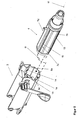
- the holding part 3 is thus composed of three individual parts and can be easily installed with the actuator 4 as an assembly in the steering column, as shown in the Fig. 2 is illustrated.
- FIG. 5 shows an alternative embodiment of the steering column, in which on some of the surface portions strip-like elevations are formed.
- strip-like elevations 15, which extend along the axis 11 of the steering shaft 2 are formed on the surface sections 7b and 7c of the actuating part 4.
- the actuator 4 was in FIG. 5 opposite to the illustration in FIG. 2 shown twisted about the axis 11 of the steering shaft 2.
- two parallel strip-like elevations 14 are formed on the surface portions 8a and 8d. However, these are aligned perpendicular to the axis 11 of the steering shaft 2.
- the setting member 4 is positioned according to the rotation and displacement shown in the dashed arrow lines in the holding part 3, so that in each case a strip-like increase cooperates with a substantially flat surface portion.
- surface portions may be convex.
- An example of this is in the FIG. 6 Far exaggerated.
- the corresponding surface portion is formed with a convexity K, which is elastically pressed when closing the fixing device.
- the holding part 3 is pushed with a bias in the direction of the steering shaft 2 on the adjusting part 4. This ensures a good guidance of the actuating part 4 even when the fixing device 6 is open.
Abstract
Description
Die Erfindung betrifft eine verstellbare Lenksäule für ein Kraftfahrzeug, umfassend eine Lenkspindel, die drehbar in einem Stellteil gelagert ist, ein Halteteil und eine Fixiereinrichtung, in deren geöffnetem Zustand das Stellteil gegenüber dem Halteteil zur Einstellung der Position der Lenksäule mindestens in Axialrichtung der Lenkspindel verstellbar ist und in deren geschlossenem Zustand das Stellteil von der Fixiereinrichtung gegenüber dem Halteteil festgestellt ist.The invention relates to an adjustable steering column for a motor vehicle, comprising a steering shaft which is rotatably mounted in an actuating part, a holding part and a fixing device, in the open state, the adjusting member relative to the holding part for adjusting the position of the steering column is adjustable at least in the axial direction of the steering shaft and in the closed state, the setting part of the fixing device relative to the holding part is detected.
Verstellbare Lenksäulen dienen der Erhöhung des Komforts des Fahrers und können in ihrer Längen-, Höhen- und/oder Winkelposition verändert werden, um so die Position des Steuerrades auf die Sitzposition des Fahrers anpassen zu können. Hierzu verfügen diese Lenksäulen über ein Stellteil, dessen Lage in Bezug auf ein Halteteil veränderbar ist und mit einer Fixiereinrichtung oder einem Klemmsystem festlegbar ist.Adjustable steering columns are used to increase the comfort of the driver and can be changed in their length, height and / or angular position, so as to be able to adjust the position of the steering wheel to the driver's seating position. For this purpose, these steering columns have an actuating part whose position is variable with respect to a holding part and can be fixed with a fixing device or a clamping system.
Für verstellbare Lenksäulen stellt sich das Problem, dass die Fixiereinrichtung leichtgängig und mit geringen Wegen der Betätigungsglieder geöffnet und geschlossen werden können soll, nur wenig Bauraum einnehmen soll und gleichzeitig möglichst große Widerstände gegen ein unbeabsichtigtes Verstellen des Stellteils gegenüber dem Halteteil aufbringen soll. Insbesondere im Crashfall soll genügend Rückhaltekraft zum Öffnen des Airbags zur Verfügung gestellt werden und/oder die Energie beim Aufprall des Fahrers auf das Lenkrad kontrolliert abgebaut werden. Dieser Energieabbau kann dabei entweder im Klemmsystem selbst oder in separaten Einrichtungen, die dann üblicherweise wirkungsmässig zwischen Halteteil und Karosserie angeordnet sind, erfolgen.For adjustable steering columns, there is the problem that the fixing should be able to open and close smoothly and with little ways of the actuators, take up little space and at the same time should apply as much resistance to unintentional adjustment of the adjusting member relative to the holding part. In particular, in the event of a crash, sufficient restraining force is to be made available for opening the airbag and / or the energy in the impact of the driver on the steering wheel is reduced in a controlled manner. This energy reduction can be done either in the clamping system itself or in separate facilities, which are then usually effectively arranged between holding part and body.
In der
Der Nachteil dieser Anordnung besteht in den insgesamt relativ geringen Haltekräften und der erforderlichen Vergrösserung der linken und rechten Seitenflächen am Stellteil, die zudem durch ein zusätzliches Blechbiegeteil, das am Stellteil angeschweißt ist, realisiert ist.The disadvantage of this arrangement is the overall relatively low holding forces and the required enlargement of the left and right side surfaces on the control part, which is also realized by an additional sheet metal bent part, which is welded to the control part.
Die Anzahl der Einzelteile und Bearbeitungsschritte ist dementsprechend hoch. Die Abstützung des Stellteils gegen eine Drehung um die Klemmachse ist nicht sehr steif.The number of individual parts and processing steps is correspondingly high. The support of the actuator against rotation about the clamping axis is not very stiff.
In der
Nachteil der in diesem Stand der Technik vorgestellten Lösung ist die geringe Steifigkeit des gesamten Aufbaus. Weiter müssen zur Erreichung ausreichend großer Haltekräfte sehr hohe Betätigungskräfte und/oder Betätigungswege am Handgriff bzw. Stellhebel zum Öffnen und Schließen der Fixiereinrichtung ausgeübt werden.Disadvantage of the solution presented in this prior art is the low rigidity of the entire structure. Furthermore, in order to achieve sufficiently large holding forces, very high actuation forces and / or actuation paths must be exerted on the handle or adjusting lever for opening and closing the fixing device.
In der
Die Aufgabe der Erfindung besteht darin, eine Fixiereinrichtung für eine in der Länge, das heißt in Axialrichtung der Lenkspindel, und hinsichtlich ihres Neigungswinkels verstellbare Lenksäule bereitzustellen; die im geschlossenen Zustand zumindest in diese Axialrichtung hohe Haltekräfte gegen eine Verstellung des Stellteils gegenüber dem Halteteil aufbringt, wobei die Betätigungswege und Betätigungskräfte am Stellhebel den Komforterfordernissen des Fahrers entsprechen.The object of the invention is a fixing device for an adjustable in length, that is in the axial direction of the steering shaft, and in terms of its inclination angle steering column provide; the high holding forces in the closed state at least in this axial direction against an adjustment of the adjusting member relative to the holding part applies, wherein the actuating travel and actuating forces on the adjusting lever correspond to the comfort requirements of the driver.
Die Aufgabe der Erfindung wird durch eine Lenksäule entsprechend den Merkmalen des Anspruchs 1 gelöst. Vorteilhafte und zweckmäßige Ausgestaltungen der Erfindung sind Gegenstand der Unteransprüche.The object of the invention is achieved by a steering column according to the features of claim 1. Advantageous and expedient embodiments of the invention are the subject of the dependent claims.
Erfindungsgemäß wird hierzu eine Lenksäule der eingangs genannten Art vorgeschlagen, bei der die von der Lenkspindel weggerichtete Oberfläche des Stellteils in Umfangsrichtung mehrere erste Flächenabschnitte aufweist, die zur Lenkspindel hin gerichtete Oberfläche des Halteteils, die das Stellteil zumindest teilweise umschließt, zweite Flächenabschnitte aufweist, wobei sich die ersten und zweiten Flächenabschnitte in Richtung der Achse der Lenkspindel erstrecken und wobei zur Fixierung des Stellteils mindestens drei Paare von ersten und zweiten Flächenabschnitten zumindest teilweise in kraft- oder kraft- und formschlüssigen Kontakt bringbar sind. Durch diesen Kontakt ist das Stellteil mit dem Halteteil kraftschlüssig gegen eine Verschiebung in Richtung der Achse der Lenkspindel gesichert. Der Kontakt bewirkt bereits bei geringen Normalkräften bzw. Flächenpressungen eine hohe Steifigkeit der Anordnung und hohe Haltekräfte gegen eine Verschiebung des Stellteils gegenüber dem Halteteil. Für den Fall, dass die Fixiereinrichtung geöffnet ist, dienen die Flächen als Führungen, sodass das Stellteil gut gegenüber dem Halteteil vom Fahrer verstellt werden kann.According to the invention, a steering column of the aforementioned type is proposed for this purpose, in which the direction away from the steering shaft surface of the actuator in the circumferential direction has a plurality of first surface portions, the steering spindle directed towards the surface of the holding part, which surrounds the actuating part at least partially, second surface portions, wherein the first and second surface portions extend in the direction of the axis of the steering spindle and at least three pairs of first and second surface portions are at least partially in non-positive or frictional and positive contact brought to fix the adjusting part. As a result of this contact, the actuating part with the retaining part is secured non-positively against displacement in the direction of the axis of the steering spindle. The contact causes even at low normal forces or surface pressures a high rigidity of the arrangement and high holding forces against displacement of the actuating part relative to the holding part. In the event that the fixing device is opened, the surfaces serve as guides, so that the control part can be easily adjusted relative to the holding part by the driver.
Da das Halteteil in der Halteklammer um eine Schwenkachse drehbar gelagert ist, kann die Lenksäule in der Winkellage verschwenkt werden. Hierzu sind in einem Abstand von der Schwenkachse Langlöcher vorgesehen, die in Seitenwangen der Halteklammer vorgesehen sind und von der Fixiereinrichtung, die z.B. einen Spannbolzen umfasst, durchgriffen werden. Dabei können die Langlöcher sowohl gerade verlaufen als auch eine gebogene Kreisabschnittsform aufweisen, deren Mittelpunkt auf der Schwenkachse liegt.Since the holding part is rotatably mounted in the retaining clip about a pivot axis, the steering column can be pivoted in the angular position. For this purpose, slots are provided at a distance from the pivot axis, which are provided in side cheeks of the retaining clip and by the fixing device, which includes, for example, a clamping bolt, are penetrated. The slots may be both straight and have a curved circular section shape, the center of which lies on the pivot axis.
Bevorzugt sind die Schwenkachse an dem einen Ende und die Langlöcher sowie die Fixiereinrichtung an dem anderen Ende der Halteklammer (in Längsrichtung der Lenkspindel gesehen) angeordnet. Dadurch können bei einer bestimmten Fixierkraft der Fixiereinrichtung besonders hohe Kräfte an dem dem Lenkrad zugewandten Ende der Lenkspindel abgestützt werden.Preferably, the pivot axis at one end and the slots and the fixing device at the other end of the retaining clip (seen in the longitudinal direction of the steering shaft) are arranged. As a result, particularly high forces can be supported on the steering wheel facing the end of the steering shaft at a certain fixing force of the fixing device.
Das Halteteil weist eine Öffnung entlang seiner Längsachse auf, die beim Schließen der Fixiereinrichtung verkleinerbar ist, so dass die ersten und zweiten Flächenabschnitte an Stellteil bzw. Halteteil mit einer zur Fixierung des Stellteils erforderlichen Flächenpressung miteinander in Kontakt bringbar sind, wobei jeweils mindestens einer der in Kontakt gebrachten Flächenabschnitte nahezu eben ausgebildet ist.The holding part has an opening along its longitudinal axis, which can be reduced when the fixing device is closed, so that the first and second surface sections can be brought into contact with the adjusting part or holding part with a surface pressure required for fixing the setting part, wherein at least one of the in Contact brought surface sections is almost flat.
Der erfindungsgemäße Lösungsansatz besteht darin, durch jeweils zwei möglichst große Flächenkontakte am Umfang des Stellteils möglichst hohe Reibkräfte zu erzeugen, die zu hohen Verschiebekräften im geschlossenen Zustand der Fixiereinrichtung führen und gleichzeitig die Führung im geöffneten Zustand der Fixiereinrichtung zu gewährleisten. Weiter soll eine Abstützung in möglichst vielen Raumrichtungen erfolgen, um die Steifigkeit zu erhöhen und die Schwingungsneigung zu verringern. Über die Auslegung der Flächenpaarungen und entsprechender Flächenpressungen können die Verschiebekräfte und die Haltekräfte eingestellt werden. Es werden deshalb ebene Flächenabschnitte bevorzugt.The solution according to the invention consists in generating as many friction forces as possible on the circumference of the setting part by means of two large area contacts which lead to high displacement forces in the closed state of the fixing device and at the same time to ensure guidance in the opened state of the fixing device. Furthermore, a support should be made in as many directions as possible in order to increase the rigidity and reduce the tendency to oscillate. About the design of the surface pairings and corresponding surface pressures, the displacement forces and the holding forces can be adjusted. Therefore, flat surface sections are preferred.
Ein derartiges Stellteil und ein derartiges Halteteil kann beispielsweise in einfacher Weise durch eine Blechbiege- und -stanzoperation hergestellt werden und dabei werden die Flächenabschnitte nahezu eben ausgebildet. Da bei Biege- und Stanzoperationen der Werkstoff nur wenig Dehnung erfährt, gibt es fertigungsbedingte Einschränkungen in der Präzision der Ebenheit der so geformten Flächen. Wie Versuche gezeigt haben, genügen aber diese Genauigkeiten, um ausreichend hohe Widerstandskräfte gegen eine Verschiebung des Stellteils gegenüber dem Halteteil zu erreichen.Such an actuating part and such a holding part can be produced, for example, in a simple manner by a sheet metal bending and punching operation and thereby the surface portions are formed almost flat. Since the material experiences only little elongation during bending and punching operations, there are production-related restrictions in the precision of the flatness of the surfaces thus formed. As tests have shown, but these accuracies are sufficient to achieve sufficiently high resistance forces against displacement of the actuating part relative to the holding part.
Die Herstellung exakter ebener Flächen stellt jedoch auch bei anderen Fertigungsverfahren hohe Anforderungen an die Fertigung. Dadurch kann es bei zu ungenauer Auslegung der Flächen zu einem Verkanten oder Verklemmen des Stellteils gegenüber dem Halteteil kommen.However, the production of exact flat surfaces also places high demands on production in other production processes. This can lead to tilting or jamming of the actuating part relative to the holding part to inaccurate design of the surfaces.
Zur Senkung der Anforderungen an die Genauigkeit der Herstellung der einzelnen Flächenabschnitte ist in einer Weiterbildung der Erfindung vorgesehen, dass mindestens einer der ersten und/oder zweiten Flächenabschnitte zur Ausbildung von diskreten Druckpunkten mindestens eine leistenartige Erhöhung aufweist. In diesem Fall erfolgt die Kraftübertragung über den Kontakt, der sich zwischen der leistenartigen Erhöhung und dem gegenüber liegenden Flächenabschnitt bildet. Dadurch sind die Anforderungen an die Herstellgenauigkeit gesenkt. Geringe Passungenauigkeiten können so durch elastische Rückfederungen in den Flächenabschnitten ausgeglichen werden. Zur sicheren Führung und Verhinderung des Verkantens ist dabei bevorzugt mindestens eine leistenartige Erhöhung in Richtung der Achse der Lenkspindel ausgerichtet. Zur Erhöhung der Steifigkeit wird, bevorzugt an einem anderen Flächenabschnitt, zumindest eine leistenartige Erhöhung vorgesehen, die senkrecht zur Achse der Lenkspindel ausgerichtet ist. Weiter bevorzugt werden zwei derartige Erhöhungen in Verstellrichtung hintereinander liegend angeordnet.To reduce the requirements on the accuracy of the production of the individual surface portions is provided in a development of the invention that at least one of the first and / or second surface portions to form discrete pressure points has at least one strip-like increase. In this case, the power transmission takes place via the contact, which forms between the strip-like elevation and the opposite surface portion. As a result, the demands on the manufacturing accuracy are lowered. Low fit inaccuracies can be compensated by elastic springback in the surface sections. For safe guidance and prevention of tilting, at least one strip-like elevation in the direction of the axis of the steering spindle is preferably aligned. To increase the rigidity, at least one strip-like elevation is provided, preferably at another surface portion, which is aligned perpendicular to the axis of the steering shaft. More preferably, two such elevations are arranged one behind the other in the adjustment direction.
Alternativ oder auch in Kombination zum Einsatz leistenartiger Erhöhungen werden in einer vorteilhaften Weiterbildung der Erfindung die Flächenkontakte noch durch eine leichte Bombierung der nahezu eben ausgebildeten Flächen erhöht, sodass beim Schließen der Fixiereinrichtung zunächst die konvex aus der Oberfläche herausstehenden Teilbereiche der ersten und/oder zweiten Flächenabschnitte in Kontakt kommen und sich während des Vorgangs des Schließens unter elastischer Umformung ein großflächiger Flächenkontakt ausbildet. Dabei werden die Eigenspannungen günstig erhöht, sodass die Steifigkeit der Lenksäule noch weiter erhöht wird. Konvexitäten, das heißt Überhöhungen der Flächenmitte in Bezug zum Rand der nahezu ebenen Fläche, von bis zu 0,05 mm haben sich als sinnvoll und nützlich erwiesen. Wenn die Konvexitäten zu groß sind, kann sich der großflächige Kontakt nicht mehr durch einfache elastische Verformung herstellen, sodass die Steifigkeit der Anordnung wieder sinkt.Alternatively or in combination to use strip-like increases in an advantageous development of the invention, the surface contacts are still increased by a slight crowning of almost flat surfaces, so when closing the fixing initially the convex protruding from the surface portions of the first and / or second surface portions come into contact and forms a large area surface contact during the process of closing under elastic deformation. The internal stresses are favorably increased, so that the rigidity of the steering column is further increased. Convexities, ie elevations of the center of area with respect to the edge of the nearly flat surface of up to 0.05 mm, have proved to be useful and useful. If the convexities are too big, it may the large-area contact no longer produce by simple elastic deformation, so that the rigidity of the arrangement decreases again.
Im Weiteren soll die Erfindung anhand schematischer Figuren erläutert werden. Es zeigen:
- Figur 1:
- eine Ausführungsform der erfindungsgemäßen Lenksäule,
Figur 2- eine Ausführungsform der erfindungsgemäßen Lenksäule in ausein- andergezogener Darstellung der Einzelteile,
- Figur 3:
- einen Schnitt durch die Fixiereinrichtung in geöffnetem Zustand,
- Figur 4:
- einen Schnitt durch die Fixiereinrichtung in geschlossenem Zustand,
- Figur 5:
- eine alternative Ausführungsform des Halte- und Stellteils,
- Figur 6:
- einen Teilschnitt durch die Fixiereinrichtung in einer alternativen Aus- führungsform in geöffnetem Zustand.
- FIG. 1:
- An embodiment of the steering column according to the invention,
- FIG. 2
- An embodiment of the steering column according to the invention in an exploded view of the individual parts,
- FIG. 3:
- a section through the fixing device in the open state,
- FIG. 4:
- a section through the fixing device in the closed state,
- FIG. 5:
- an alternative embodiment of the holding and setting part,
- FIG. 6:
- a partial section through the fixing device in an alternative embodiment in the open state.
In allen Figuren sind zur besseren Übersicht Teile der Lenkwelle und die Befestigung am Fahrzeug weggelassen, da sie nicht wesentlich für die Erfindung sind.In all figures, parts of the steering shaft and the attachment to the vehicle are omitted for clarity, since they are not essential to the invention.
Die Lenkspindel 2 ist im Stellteil 4 drehbar um die Achse 11 gelagert und wird vom nicht gezeigten Steuerrad vom Fahrer betätigt. Das Stellteil 4 ist im Halteteil 3 axial verschiebbar geführt. Das Halteteil 3 ist in der Halteklammer 5 um die Schwenkachse 21 drehbar gelagert. Mit der Fixiereinrichtung 6, die hier als Klemmsystem ausgebildet ist, umfassend einen Stellhebel 10, einen Spannbolzen 9 sowie einen Gegenhalter 20, eine Kulissenscheibe 19 und einen Nocken 18, werden die Halteklammer 5, das Halteteil 3 und das Stellteil 4 in ihrer Bewegung gegeneinander fixiert bzw. freigegeben. Durch Drehen des Stellhebels 10 wird der Nocken 18 in der Kulissenscheibe 19 verschoben, sodass der Spannbolzen 9 verschoben wird. Die Halteklammer 5 ist am Fahrzeug mit hier nicht dargestellten Elementen befestigt.The steering
Im Fall, dass das Klemmsystem 6 geöffnet ist (vgl.
Im Fall, dass das Klemmsystem 6 geschlossen ist (vgl.
Alternativ sind das Halteteil 3 und das Stellteil 4 so ausgelegt, dass nur drei Paare von ersten Flächenabschnitten 7a, 7d, 7e des Halteteils 3 und zweiten Flächenabschnitten 8a, 8d, 8e des Stellteils 2 zusammengepresst werden.Alternatively, the holding
Mit der gezeigten Lösung lassen sich problemlos die Verschiebekraft im geöffneten Zustand der Fixiereinrichtung auf 1/15 des Wertes der Verschiebekraft im geschlossenen Zustand der Fixiereinrichtung einstellen und gleichzeitig ein durch zu großes Spiel entstehendes störendes Unsicherheitsgefühl vermeiden.With the solution shown can be easily adjust the displacement force in the open state of the fixing device to 1/15 of the value of the displacement force in the closed state of the fixing and at the same time avoid a resulting from excessive play disturbing uncertainty.
Damit die Seitenwangen 5a, 5b der Halteklammer 5 leichter zusammengedrückt werden können, ist ein Schlitz 13 vorgesehen.So that the
In der bevorzugten Ausführungsform wird das Halteteil 3 als Blechbiege- und - stanzteil, ggf. mit entsprechenden Prägeoperationen, hergestellt. In der gezeigten Ausführungsform sind die Flächenabschnitte 8a und 8d an zwei separaten Bauteilen ausgebildet, die wie die Seitenwangen 3a und 3b vom Spannbolzen 9 durchsetzt werden. Das Halteteil 3 umschließt dabei das Stellteil 4 nicht vollständig und besitzt an seiner Oberseite eine Öffnung, die sich entlang seiner Längsachse 12 erstreckt.
Bevorzugt fällt die Längsachse 12 des Halteteils 3 mit der Achse 11 der Lenkspindel 2 zusammen.In the preferred embodiment, the holding
Preferably, the
Ebenso wird das Stellteil 4 und die Halteklammer 5 bevorzugt in einer Blechbiege- und Stanztechnologie hergestellt.Likewise, the
Die Fertigungstoleranzen des Stell- und Halteteils können in einfacher Weise bei der Montage ausgeglichen werden, indem die eingesetzten Ecken, die die Flächenabschnitte 8a und 8d (
Die
Im Halteteil 3 sind an den Flächenabschnitten 8a und 8d jeweils zwei parallel angeordnete leistenartige Erhöhungen 14 ausgebildet. Diese sind allerdings senkrecht zur Achse 11 der Lenkspindel 2 ausgerichtet.The
In the holding
Zur Montage wird das Stellteil 4 entsprechend der mit den gestrichelten Pfeillinien dargestellten Verdrehung und Verschiebung in das Halteteil 3 positioniert, sodass jeweils eine leistenartige Erhöhung mit einem im Wesentlichen ebenen Flächenabschnitt zusammenwirkt.For assembly, the setting
In einer weiteren Ausführung können Flächenabschnitte konvex ausgebildet sein. Ein Beispiel dafür ist in der
Es ist offensichtlich, dass beliebige Kombinationen von leistenartigen Erhöhungen längs oder/und quer zur Achse 11 der Lenkspindel, eben ausgebildeten Flächenabschnitten, bombierten oder gewölbt ausgebildeten Flächenabschnitten möglich sind und je nach Anwendungsfall eingesetzt werden.It is obvious that any combinations of strip-like elevations along and / or transversely to the
Mit Vorteil wird das Halteteil 3 mit einer Vorspannung in Richtung Lenkspindel 2 über das Stellteil 4 geschoben. Damit ist auch bei geöffneter Fixiereinrichtung 6 eine gute Führung des Stellteils 4 gewährleistet.Advantageously, the holding
Weiter vorteilhaft ist es, die Halteklammer 5 fest und auch im Crashfall unverschiebbar mit dem Fahrzeug zu verbinden, wobei die gesamte Energieabsorption im Crashfall durch die Verschiebung des Stellteils 4 gegenüber dem Halteteil 3 erfolgt.It is also advantageous to connect the retaining
In den Figuren sind nur Beispiele für eine erfindungsgemäße Lenksäule gezeigt, bei denen der Spannbolzen 9 oberhalb der Lenkspindel 2 angeordnet ist. Diese Anordnung bietet den Vorteil einer kleineren Bauhöhe. Es kann aber für bestimmte Fahrzeuge sinnvoll sein, beispielsweise aus Gründen des Packaging, den Spannbolzen unterhalb der Lenkspindel anzuordnen. Auch für derartige Bauformen ist die Lehre der Erfindung anwendbar.In the figures, only examples of a steering column according to the invention are shown, in which the
Es ist nahe liegend, dass alle Ausführungsformen der erfindungsgemäßen Lösung sich mit den bekannten Arten von Fixiereinrichtungen für eine Höhen- und/oder Neigungsverstellung kombinieren lassen. So können ebenso Systeme mit Lamellen oder Verzahnungen zur Lagefixierung verwendet werden. Ebenso können zum Aufbringen der Spannung anstelle der Nocken und Kulissenscheibe beispielsweise Systeme mit Wälzkörpern oder Spindelelementen angewendet werden.It is obvious that all embodiments of the solution according to the invention can be combined with the known types of fixing devices for height and / or inclination adjustment. Thus, systems with slats or gears can be used to fix the position. Likewise, for example, systems with rolling elements or spindle elements can be used to apply the voltage instead of the cam and link plate.
- 11
- Lenksäulesteering column
- 22
- Lenkspindelsteering shaft
- 33
- Halteteilholding part
- 3a3a
- Seitenflächeside surface
- 3b3b
- Seitenflächeside surface
- 44
- Stellteiladjusting part
- 55
- Halteklammerretaining clip
- 5a5a
- Seitenwangeside cheek
- 5b5b
- Seitenwangeside cheek
- 66
- Fixiereinrichtungfixing
- 7a7a
- Erster FlächenabschnittFirst surface section
- 7b7b
- Erster FlächenabschnittFirst surface section
- 7c7c
- Erster FlächenabschnittFirst surface section
- 7d7d
- Erster FlächenabschnittFirst surface section
- 7e7e
- Erster FlächenabschnittFirst surface section
- 8a8a
- Zweiter FlächenabschnittSecond surface section
- 8b8b
- Zweiter FlächenabschnittSecond surface section
- 8c8c
- Zweiter FlächenabschnittSecond surface section
- 8d8d
- Zweiter FlächenabschnittSecond surface section
- 8e8e
- Zweiter FlächenabschnittSecond surface section
- 99
- Spannbolzenclamping bolt
- 1010
- Stellhebellever
- 1111
- Achse LenkspindelAxle steering spindle
- 1212
- Längsachse HalteteilLongitudinal axis holding part
- 1313
- Schlitzslot
- 1414
- Leistenartige ErhöhungIngot-like elevation
- 1515
- Leistenartige ErhöhungIngot-like elevation
- 1616
- LanglochLong hole
- 1717
- LanglochLong hole
- 1818
- Nockencam
- 1919
- Kulissenscheibelink disk
- 2020
- Gegenhalterbackstop
- 2121
- Schwenkachseswivel axis
- KK
- Konvexitätconvexity
Claims (15)
- Adjustable steering column (1) for a motor vehicle, comprising:a) a steering shaft (2) which is mounted so as to be able to rotate about its axis (11) in an adjusting part (4),b) a holding clamp (5) which is attached to the vehicle for the purpose of holding the steering column (1),c) a holding part (3), andd) a fixing device (6), in the open state of which the adjusting part (4) can be adjusted with respect to the holding part (3) at least in the axial direction of the steering shaft (2) in order to adjust the position of the steering column (1), and in the closed state of the fixing device the adjusting part (4) is fixed with respect to the holding part (3) by means of the fixing device (6),e) wherein the surface of the adjusting part (4) which is directed away from the steering shaft (2) comprises in the peripheral direction a plurality of first planar surface portions (7a, 7b, 7c, 7d, 7e),f) and the surface of the holding part (3) which is directed towards the steering shaft (2) and at least partially surrounds the adjusting part (4) comprises second planar surface portions (8a, 8b, 8c, 8d, 8e),g) wherein the first and second surface portions extend in the direction of the axis (11) of the steering shaft (2) and wherein at least three pairs of first and second planar surface portions (7a, 8a, 7b, 8b, 7c, 8c, 7d, 8d, 7e, 8e) can be brought at least partially into non-positive contact or non-positive and positive contact for the purpose of fixing the adjusting part (4),h) and wherein the holding clamp (5) comprises side cheeks (5a, 5b) which can be drawn together by closing the fixing device (6) and as a consequence the holding part (3) can be fixedly clamped, characterised in thati) the holding clamp (5) is formed as a single-piece component and the holding part (3) is mounted in the holding clamp (5) so as to be able to rotate about a pivot axis (21).
- Steering column as claimed in claim 1, characterised in that the pivot axis (21) passes through the side cheeks (5a, 5b).
- Steering column as claimed in any one of claims 1 or 2, characterised in that the side cheeks (5a, 5b) are provided with oblong holes (16, 17) which are disposed spaced apart from the pivot axis (21) as seen in the longitudinal direction of the steering column.
- Steering column as claimed in claim 3, characterised in that the pivot axis (21) is disposed at one end of the holding clamp (5) and the oblong holes (16, 17) are disposed at the other end.
- Steering column as claimed in any one of the preceding claims, characterised in that at least one of the first and/or second surface portions comprises at least one strip-like elevation (14, 15) for the purpose of forming discrete pressure points.
- Steering column as claimed in claim 5, characterised in that at least one strip-like elevation (14, 15) is aligned in the direction of the axis of the steering shaft (11).
- Steering column for a motor vehicle as claimed in claim 5 or 6, characterised in that at least one strip-like elevation (14, 15) is aligned perpendicularly with respect to the axis of the steering shaft (11).
- Steering column for a motor vehicle as claimed in any one of the preceding claims, characterised in that at least one of the surface portions (7a-7e, 8a-8e) is cambered, so that it comprises a convexity (K).
- Steering column as claimed in the preceding claim, characterised in that the highest point of the convexity (K) protrudes beyond an imaginary planar reference surface portion by a maximum of 0.05 mm.
- Steering column as claimed in any one of the preceding claims, characterised in that the holding part (3) comprises an opening along its longitudinal axis (12) which can be decreased in size as the fixing device is being closed, so that the surface portions (7a-7e, 8a-8e) can be brought into contact with each other by means of a surface pressure required for fixing the adjusting part (4).
- Steering column as claimed in any one or several of the preceding claims, characterised in that precisely 4 pairs (7a, 8a, 7b, 8b, 7c, 8c, 7d, 8d) of first and second surface portions can be brought at least partially into contact.
- Steering column as claimed in any one of the preceding claims, characterised in that the holding clamp (5) comprises a U-shaped cross-section.
- Steering column as claimed in any one of the preceding claims, characterised in that when the fixing device (6) is in the open state, the holding part (3) can be adjusted with respect to the holding clamp (5) and when the fixing device is in the closed state, the holding part (3) is fixed.
- Steering column as claimed in claims 10 to 13, characterised in that the holding part (3) has a pulling bolt (9) passing through it which moves in its axial direction as the fixing device (6) is being opened and closed and as a consequence the opening in the holding part is increased or decreased in size.
- Steering column as claimed in any one of the preceding claims, characterised in that the holding clamp (5) has a pulling bolt (9) passing through it.
Priority Applications (1)
| Application Number | Priority Date | Filing Date | Title |
|---|---|---|---|
| PL06762687T PL1910148T5 (en) | 2005-07-22 | 2006-07-19 | Adjustable steering column for a motor vehicle |
Applications Claiming Priority (2)
| Application Number | Priority Date | Filing Date | Title |
|---|---|---|---|
| DE102005034952A DE102005034952B3 (en) | 2005-07-22 | 2005-07-22 | Adjustable steering column for a motor vehicle |
| PCT/EP2006/007086 WO2007009760A1 (en) | 2005-07-22 | 2006-07-19 | Adjustable steering column for a motor vehicle |
Publications (3)
| Publication Number | Publication Date |
|---|---|
| EP1910148A1 EP1910148A1 (en) | 2008-04-16 |
| EP1910148B1 true EP1910148B1 (en) | 2010-12-29 |
| EP1910148B2 EP1910148B2 (en) | 2015-06-10 |
Family
ID=36968907
Family Applications (1)
| Application Number | Title | Priority Date | Filing Date |
|---|---|---|---|
| EP06762687.9A Active EP1910148B2 (en) | 2005-07-22 | 2006-07-19 | Adjustable steering column for a motor vehicle |
Country Status (7)
| Country | Link |
|---|---|
| US (1) | US7918483B2 (en) |
| EP (1) | EP1910148B2 (en) |
| AT (1) | ATE493319T1 (en) |
| DE (4) | DE102005034952B3 (en) |
| ES (1) | ES2358750T5 (en) |
| PL (1) | PL1910148T5 (en) |
| WO (1) | WO2007009760A1 (en) |
Cited By (2)
| Publication number | Priority date | Publication date | Assignee | Title |
|---|---|---|---|---|
| CN104540721A (en) * | 2012-04-10 | 2015-04-22 | 蒂森克虏伯普利斯坦股份公司 | Lightweight steering column composed of fibre composite material |
| EP3075633A1 (en) | 2015-03-31 | 2016-10-05 | FUJI KIKO Co., Ltd. | Steering column device |
Families Citing this family (23)
| Publication number | Priority date | Publication date | Assignee | Title |
|---|---|---|---|---|
| EP2323947B1 (en) | 2008-08-06 | 2019-07-03 | Life Technologies Corporation | Water-dispersable nanoparticles |
| DE202008017718U1 (en) | 2008-10-01 | 2010-07-15 | Thyssenkrupp Presta Ag | Shaft supported by a rolling bearing |
| DE102009051107B3 (en) * | 2009-10-28 | 2011-04-28 | Thyssenkrupp Presta Ag | Support for swiveling storage of steering shaft of steering column for motor vehicle, comprises jacket pipe of steering column, which has inner ring that is formed opposite to steering shaft |
| US9073567B2 (en) * | 2011-05-18 | 2015-07-07 | Nsk Ltd. | Steering apparatus for an automobile |
| DE102011054606B3 (en) | 2011-10-19 | 2013-02-28 | Thyssenkrupp Presta Aktiengesellschaft | Steering spindle bearing unit for rotatably supporting a steering spindle |
| DE102011054597A1 (en) * | 2011-10-19 | 2013-04-25 | Thyssenkrupp Presta Aktiengesellschaft | Steering shaft bearing unit |
| DE102011054598B3 (en) | 2011-10-19 | 2013-01-17 | Thyssenkrupp Presta Ag | Steering spindle bearing unit for rotatably supporting a steering spindle |
| DE102011056674B3 (en) * | 2011-10-19 | 2012-12-06 | Thyssenkrupp Presta Aktiengesellschaft | Steering column for motor car, has clamping bolt penetrating through side walls of bracket part, and penetrating bearing part into bearing part bead and steering shaft bearing unit in steering shaft bearing unit bead |
| DE102013001442B3 (en) | 2013-01-29 | 2014-03-13 | Thyssenkrupp Presta Aktiengesellschaft | Steering column in fiber composite technology, based on pultrusion and braiding and / or winding technology |
| GB2511565B (en) * | 2013-03-08 | 2015-04-01 | Nsk Deutschland Gmbh | Apparatus and method for a steering column |
| AT514088B1 (en) | 2013-06-20 | 2014-10-15 | Thyssenkrupp Presta Ag | Steering column for a motor vehicle and method for producing a steering column |
| DE102013021201A1 (en) | 2013-12-17 | 2015-06-18 | Daimler Ag | Steering column for a motor vehicle |
| JP6192565B2 (en) | 2014-02-21 | 2017-09-06 | 富士機工株式会社 | Steering column device |
| DE102015216348A1 (en) * | 2015-08-26 | 2017-03-02 | Thyssenkrupp Ag | Clamping device of an adjustable steering column for motor vehicles |
| DE102015216715A1 (en) | 2015-09-01 | 2017-03-02 | Thyssenkrupp Ag | Adjustable steering column for motor vehicles with energy absorber for vehicle crash |
| DE102015217761B3 (en) | 2015-09-16 | 2016-10-13 | Thyssenkrupp Ag | Steering column for motor vehicles with energy absorber in the event of a crash |
| DE102015225488B3 (en) | 2015-12-16 | 2016-12-22 | Thyssenkrupp Ag | Adjustable steering column for motor vehicles with energy absorption device |
| WO2017135384A1 (en) * | 2016-02-04 | 2017-08-10 | 日本精工株式会社 | Steering apparatus |
| JP6621359B2 (en) * | 2016-03-31 | 2019-12-18 | 富士機工株式会社 | Steering column device |
| DE102016220140A1 (en) * | 2016-10-14 | 2018-04-19 | Thyssenkrupp Ag | Steering column for a motor vehicle and method for producing a steering column |
| FR3075744B1 (en) * | 2017-12-27 | 2020-12-04 | Robert Bosch Automotive Steering Vendome | STEERING COLUMN |
| WO2021099595A1 (en) * | 2019-11-22 | 2021-05-27 | Robert Bosch Automotive Steering Vendôme | System for adjusting a resistive force against a relative translational movement between two telescopic elements |
| DE102020201058A1 (en) * | 2020-01-29 | 2021-07-29 | Thyssenkrupp Ag | Steering column for a motor vehicle |
Family Cites Families (37)
| Publication number | Priority date | Publication date | Assignee | Title |
|---|---|---|---|---|
| US3877670A (en) * | 1973-04-18 | 1975-04-15 | Scott & Fetzer Co | Extensible support structure |
| IT1091449B (en) * | 1977-11-09 | 1985-07-06 | Fiat Veicoli Ind | DEVICE FOR THE REGISTRATION OF THE STEERING SETUP OF MOTOR VEHICLES |
| ES8104096A1 (en) * | 1980-07-30 | 1981-04-01 | Bendiberica Sa | System for adjusting the position of a steering wheel on a vehicle. |
| GB2116496B (en) | 1982-03-09 | 1985-08-14 | Gen Motors Ltd | Steering column mounting assemblies |
| SE8803943D0 (en) * | 1988-10-31 | 1988-10-31 | Ffv Autotech Ab | STEERING MOUNTING PARTS WITH SLIDING AND TIP FUNCTION |
| US5009121A (en) * | 1989-07-07 | 1991-04-23 | Nippon Seiko Kabushiki Kaisha | Telescopic steering column device |
| DE4103548C1 (en) * | 1991-02-06 | 1992-04-23 | Mercedes-Benz Aktiengesellschaft, 7000 Stuttgart, De | |
| GB2259132A (en) * | 1991-08-27 | 1993-03-03 | Torrington Co | Locking device for adjustable steering column. |
| GB2273338A (en) * | 1992-12-02 | 1994-06-15 | Torrington Co | Steering column clamping mechanism. |
| FR2701682B1 (en) * | 1993-02-17 | 1995-05-24 | Peugeot | Retractable steering column assembly in the event of an impact. |
| FR2714647B1 (en) | 1994-01-06 | 1996-03-15 | Nacam | Holding device for a motor vehicle steering column. |
| US5722299A (en) * | 1994-06-30 | 1998-03-03 | Fuji Kiko Co., Ltd. | Adjustable steering column assembly for a vehicle |
| JP3415953B2 (en) * | 1995-02-03 | 2003-06-09 | 日本精工株式会社 | Steering column support device |
| US5788277A (en) * | 1995-03-30 | 1998-08-04 | Nsk Ltd. | Tilt type steering apparatus |
| US5678454A (en) * | 1995-06-15 | 1997-10-21 | Trw Inc. | Steering column |
| GB9704808D0 (en) † | 1997-03-07 | 1997-04-23 | Lucas Ind Plc | Improvements relating to steering assemblies |
| GB9716747D0 (en) * | 1997-08-08 | 1997-10-15 | Lucas Ind Plc | Improvements relating to steering assemblies |
| US5988010A (en) * | 1998-05-04 | 1999-11-23 | General Motors Corporation | Adjustable steering column for motor vehicle |
| US6036228A (en) * | 1998-05-04 | 2000-03-14 | General Motors Corporation | Adjustable steering column for motor vehicle |
| FR2778704B1 (en) | 1998-05-12 | 2000-07-21 | Lemforder Nacam Sa | DEVICE FOR TIGHTENING A SYSTEM FOR ADJUSTING THE POSITION OF AN ELEMENT IN RELATION TO ANOTHER ELEMENT |
| JP2000118415A (en) * | 1998-10-09 | 2000-04-25 | Fuji Kiko Co Ltd | Steering column |
| US6139057A (en) * | 1999-02-04 | 2000-10-31 | Delphi Technologies, Inc. | Position control apparatus for steering column |
| DE60133331T3 (en) * | 2000-02-15 | 2012-12-06 | Nsk Ltd. | Steering for an automobile |
| US6357317B1 (en) † | 2000-06-16 | 2002-03-19 | Trw Inc. | Steering column |
| US6357318B1 (en) * | 2000-06-16 | 2002-03-19 | Trw Inc. | Steering column |
| FR2818602B1 (en) * | 2000-12-26 | 2003-03-28 | Nacam | DEVICE FOR TIGHTENING AN ELEMENT ADJUSTABLE TO A SUPPORT ASSEMBLY |
| JP3886766B2 (en) * | 2001-01-11 | 2007-02-28 | 富士機工株式会社 | Tilt and telescopic steering column device |
| JP3933409B2 (en) † | 2001-03-29 | 2007-06-20 | 株式会社ジェイテクト | Steering device |
| US6957595B2 (en) * | 2001-07-13 | 2005-10-25 | Deere & Co. | Tilt steering wheel mechanism |
| JP2003118595A (en) † | 2001-08-06 | 2003-04-23 | Nsk Ltd | Vehicular steering device and its manufacturing method |
| JP2003127874A (en) * | 2001-10-23 | 2003-05-08 | Fuji Kiko Co Ltd | Shock absorbing tilt steering column |
| JP4147579B2 (en) | 2002-01-17 | 2008-09-10 | 日本精工株式会社 | Steering device |
| US6666478B2 (en) * | 2002-05-01 | 2003-12-23 | Trw Inc. | Steering column |
| CN100364831C (en) * | 2002-05-10 | 2008-01-30 | 日本精工株式会社 | Steering device |
| DE10232041A1 (en) † | 2002-07-16 | 2004-02-05 | Thyssenkrupp Presta Ag | steering column |
| WO2004086225A1 (en) | 2003-03-24 | 2004-10-07 | Fujitsu Limited | Virtual computer system |
| EP1612120B1 (en) * | 2003-03-26 | 2009-06-03 | Nsk Ltd. | Steering device for motor vehicle |
-
2005
- 2005-07-22 DE DE102005034952A patent/DE102005034952B3/en not_active Expired - Fee Related
-
2006
- 2006-07-19 EP EP06762687.9A patent/EP1910148B2/en active Active
- 2006-07-19 ES ES06762687.9T patent/ES2358750T5/en active Active
- 2006-07-19 DE DE502006008616T patent/DE502006008616D1/en active Active
- 2006-07-19 PL PL06762687T patent/PL1910148T5/en unknown
- 2006-07-19 AT AT06762687T patent/ATE493319T1/en active
- 2006-07-19 DE DE202006021191U patent/DE202006021191U1/en not_active Expired - Lifetime
- 2006-07-19 WO PCT/EP2006/007086 patent/WO2007009760A1/en active Application Filing
- 2006-07-19 DE DE202006021160U patent/DE202006021160U1/en not_active Expired - Lifetime
- 2006-07-19 US US11/996,150 patent/US7918483B2/en active Active
Cited By (3)
| Publication number | Priority date | Publication date | Assignee | Title |
|---|---|---|---|---|
| CN104540721A (en) * | 2012-04-10 | 2015-04-22 | 蒂森克虏伯普利斯坦股份公司 | Lightweight steering column composed of fibre composite material |
| EP3075633A1 (en) | 2015-03-31 | 2016-10-05 | FUJI KIKO Co., Ltd. | Steering column device |
| US9505426B2 (en) | 2015-03-31 | 2016-11-29 | Fuji Kiko Co., Ltd. | Steering column device |
Also Published As
| Publication number | Publication date |
|---|---|
| US7918483B2 (en) | 2011-04-05 |
| DE202006021191U1 (en) | 2013-07-01 |
| ES2358750T5 (en) | 2015-09-21 |
| ATE493319T1 (en) | 2011-01-15 |
| PL1910148T3 (en) | 2011-05-31 |
| DE502006008616D1 (en) | 2011-02-10 |
| PL1910148T5 (en) | 2016-08-31 |
| WO2007009760A1 (en) | 2007-01-25 |
| DE202006021160U1 (en) | 2013-03-27 |
| US20080290641A1 (en) | 2008-11-27 |
| ES2358750T3 (en) | 2011-05-13 |
| EP1910148A1 (en) | 2008-04-16 |
| EP1910148B2 (en) | 2015-06-10 |
| DE102005034952B3 (en) | 2007-02-22 |
Similar Documents
| Publication | Publication Date | Title |
|---|---|---|
| EP1910148B1 (en) | Adjustable steering column for a motor vehicle | |
| EP1957341B1 (en) | Adjustable steering column for a motor vehicle | |
| EP2398688B1 (en) | Steering column for a motor vehicle | |
| EP2928754B1 (en) | Steering column for a motor vehicle | |
| EP2512899B1 (en) | Steering column for a motor vehicle | |
| EP2307259B1 (en) | Steering column for a motor vehicle | |
| EP1590226B1 (en) | Clamping device for a steering column | |
| DE102005035009B3 (en) | Adjustable steering column for motor vehicle, has segment that lies in area of recess in closed condition of fixing unit during through-slipping of operating unit, extends into recess and lies opposite to edge of recess | |
| DE10145896B4 (en) | Sliding device for a vehicle steering column | |
| DE102011000319B3 (en) | Locking device for locking a steering shaft bearing unit | |
| DE102009038317B4 (en) | Adjustable steering column for a motor vehicle | |
| EP2900540B1 (en) | Steering column for a motor vehicle | |
| EP2981447A1 (en) | Method for producing a steering shaft bearing unit | |
| EP3297889B1 (en) | Steering column for a motor vehicle, and energy absorption device | |
| WO2013056766A1 (en) | Steering column for a motor vehicle | |
| WO2007101565A1 (en) | Steering column arrangement for vehicles | |
| EP3908499A1 (en) | Steering column for a motor vehicle | |
| WO2007003258A1 (en) | Clamping device for a steering column | |
| EP3515790B1 (en) | Sleeve unit for an adjustable steering column of a motor vehicle | |
| EP3911553B1 (en) | Steering column for a motor vehicle | |
| EP3987199B1 (en) | Coupling element for mounting on a threaded spindle, system with a threaded spindle and a coupling element, spindle drive and steering column | |
| DE102014108321A1 (en) | Steering column for a motor vehicle |
Legal Events
| Date | Code | Title | Description |
|---|---|---|---|
| PUAI | Public reference made under article 153(3) epc to a published international application that has entered the european phase |
Free format text: ORIGINAL CODE: 0009012 |
|
| 17P | Request for examination filed |
Effective date: 20080222 |
|
| AK | Designated contracting states |
Kind code of ref document: A1 Designated state(s): AT BE BG CH CY CZ DE DK EE ES FI FR GB GR HU IE IS IT LI LT LU LV MC NL PL PT RO SE SI SK TR |
|
| RIN1 | Information on inventor provided before grant (corrected) |
Inventor name: SCHOLTEN, MICHAEL Inventor name: GALEHR, ROBERT |
|
| 17Q | First examination report despatched |
Effective date: 20090929 |
|
| GRAP | Despatch of communication of intention to grant a patent |
Free format text: ORIGINAL CODE: EPIDOSNIGR1 |
|
| GRAS | Grant fee paid |
Free format text: ORIGINAL CODE: EPIDOSNIGR3 |
|
| GRAA | (expected) grant |
Free format text: ORIGINAL CODE: 0009210 |
|
| AK | Designated contracting states |
Kind code of ref document: B1 Designated state(s): AT BE BG CH CY CZ DE DK EE ES FI FR GB GR HU IE IS IT LI LT LU LV MC NL PL PT RO SE SI SK TR |
|
| REG | Reference to a national code |
Ref country code: GB Ref legal event code: FG4D Free format text: NOT ENGLISH |
|
| REG | Reference to a national code |
Ref country code: CH Ref legal event code: EP |
|
| REG | Reference to a national code |
Ref country code: IE Ref legal event code: FG4D Free format text: LANGUAGE OF EP DOCUMENT: GERMAN |
|
| REF | Corresponds to: |
Ref document number: 502006008616 Country of ref document: DE Date of ref document: 20110210 Kind code of ref document: P |
|
| REG | Reference to a national code |
Ref country code: DE Ref legal event code: R096 Ref document number: 502006008616 Country of ref document: DE Effective date: 20110210 |
|
| REG | Reference to a national code |
Ref country code: NL Ref legal event code: VDEP Effective date: 20101229 |
|
| PG25 | Lapsed in a contracting state [announced via postgrant information from national office to epo] |
Ref country code: LT Free format text: LAPSE BECAUSE OF FAILURE TO SUBMIT A TRANSLATION OF THE DESCRIPTION OR TO PAY THE FEE WITHIN THE PRESCRIBED TIME-LIMIT Effective date: 20101229 |
|
| REG | Reference to a national code |
Ref country code: ES Ref legal event code: FG2A Ref document number: 2358750 Country of ref document: ES Kind code of ref document: T3 Effective date: 20110503 |
|
| LTIE | Lt: invalidation of european patent or patent extension |
Effective date: 20101229 |
|
| PG25 | Lapsed in a contracting state [announced via postgrant information from national office to epo] |
Ref country code: BG Free format text: LAPSE BECAUSE OF FAILURE TO SUBMIT A TRANSLATION OF THE DESCRIPTION OR TO PAY THE FEE WITHIN THE PRESCRIBED TIME-LIMIT Effective date: 20110329 Ref country code: LV Free format text: LAPSE BECAUSE OF FAILURE TO SUBMIT A TRANSLATION OF THE DESCRIPTION OR TO PAY THE FEE WITHIN THE PRESCRIBED TIME-LIMIT Effective date: 20101229 Ref country code: SE Free format text: LAPSE BECAUSE OF FAILURE TO SUBMIT A TRANSLATION OF THE DESCRIPTION OR TO PAY THE FEE WITHIN THE PRESCRIBED TIME-LIMIT Effective date: 20101229 Ref country code: CY Free format text: LAPSE BECAUSE OF FAILURE TO SUBMIT A TRANSLATION OF THE DESCRIPTION OR TO PAY THE FEE WITHIN THE PRESCRIBED TIME-LIMIT Effective date: 20101229 Ref country code: FI Free format text: LAPSE BECAUSE OF FAILURE TO SUBMIT A TRANSLATION OF THE DESCRIPTION OR TO PAY THE FEE WITHIN THE PRESCRIBED TIME-LIMIT Effective date: 20101229 Ref country code: SI Free format text: LAPSE BECAUSE OF FAILURE TO SUBMIT A TRANSLATION OF THE DESCRIPTION OR TO PAY THE FEE WITHIN THE PRESCRIBED TIME-LIMIT Effective date: 20101229 |
|
| REG | Reference to a national code |
Ref country code: PL Ref legal event code: T3 |
|
| REG | Reference to a national code |
Ref country code: IE Ref legal event code: FD4D |
|
| PG25 | Lapsed in a contracting state [announced via postgrant information from national office to epo] |
Ref country code: GR Free format text: LAPSE BECAUSE OF FAILURE TO SUBMIT A TRANSLATION OF THE DESCRIPTION OR TO PAY THE FEE WITHIN THE PRESCRIBED TIME-LIMIT Effective date: 20110330 Ref country code: PT Free format text: LAPSE BECAUSE OF FAILURE TO SUBMIT A TRANSLATION OF THE DESCRIPTION OR TO PAY THE FEE WITHIN THE PRESCRIBED TIME-LIMIT Effective date: 20110429 Ref country code: EE Free format text: LAPSE BECAUSE OF FAILURE TO SUBMIT A TRANSLATION OF THE DESCRIPTION OR TO PAY THE FEE WITHIN THE PRESCRIBED TIME-LIMIT Effective date: 20101229 Ref country code: IS Free format text: LAPSE BECAUSE OF FAILURE TO SUBMIT A TRANSLATION OF THE DESCRIPTION OR TO PAY THE FEE WITHIN THE PRESCRIBED TIME-LIMIT Effective date: 20110429 |
|
| PG25 | Lapsed in a contracting state [announced via postgrant information from national office to epo] |
Ref country code: RO Free format text: LAPSE BECAUSE OF FAILURE TO SUBMIT A TRANSLATION OF THE DESCRIPTION OR TO PAY THE FEE WITHIN THE PRESCRIBED TIME-LIMIT Effective date: 20101229 Ref country code: SK Free format text: LAPSE BECAUSE OF FAILURE TO SUBMIT A TRANSLATION OF THE DESCRIPTION OR TO PAY THE FEE WITHIN THE PRESCRIBED TIME-LIMIT Effective date: 20101229 Ref country code: NL Free format text: LAPSE BECAUSE OF FAILURE TO SUBMIT A TRANSLATION OF THE DESCRIPTION OR TO PAY THE FEE WITHIN THE PRESCRIBED TIME-LIMIT Effective date: 20101229 |
|
| PLBI | Opposition filed |
Free format text: ORIGINAL CODE: 0009260 |
|
| PG25 | Lapsed in a contracting state [announced via postgrant information from national office to epo] |
Ref country code: IE Free format text: LAPSE BECAUSE OF FAILURE TO SUBMIT A TRANSLATION OF THE DESCRIPTION OR TO PAY THE FEE WITHIN THE PRESCRIBED TIME-LIMIT Effective date: 20101229 Ref country code: DK Free format text: LAPSE BECAUSE OF FAILURE TO SUBMIT A TRANSLATION OF THE DESCRIPTION OR TO PAY THE FEE WITHIN THE PRESCRIBED TIME-LIMIT Effective date: 20101229 |
|
| PLAX | Notice of opposition and request to file observation + time limit sent |
Free format text: ORIGINAL CODE: EPIDOSNOBS2 |
|
| 26 | Opposition filed |
Opponent name: ZF SYSTEMES DE DIRECTION NACAM, S.A.S. Effective date: 20110929 |
|
| REG | Reference to a national code |
Ref country code: DE Ref legal event code: R026 Ref document number: 502006008616 Country of ref document: DE Effective date: 20110929 |
|
| BERE | Be: lapsed |
Owner name: THYSSENKRUPP PRESTA AKTIENGESELLSCHAFT Effective date: 20110731 |
|
| PG25 | Lapsed in a contracting state [announced via postgrant information from national office to epo] |
Ref country code: MC Free format text: LAPSE BECAUSE OF NON-PAYMENT OF DUE FEES Effective date: 20110731 |
|
| PLAF | Information modified related to communication of a notice of opposition and request to file observations + time limit |
Free format text: ORIGINAL CODE: EPIDOSCOBS2 |
|
| PG25 | Lapsed in a contracting state [announced via postgrant information from national office to epo] |
Ref country code: BE Free format text: LAPSE BECAUSE OF NON-PAYMENT OF DUE FEES Effective date: 20110731 |
|
| PLBB | Reply of patent proprietor to notice(s) of opposition received |
Free format text: ORIGINAL CODE: EPIDOSNOBS3 |
|
| REG | Reference to a national code |
Ref country code: AT Ref legal event code: MM01 Ref document number: 493319 Country of ref document: AT Kind code of ref document: T Effective date: 20110719 |
|
| PG25 | Lapsed in a contracting state [announced via postgrant information from national office to epo] |
Ref country code: AT Free format text: LAPSE BECAUSE OF NON-PAYMENT OF DUE FEES Effective date: 20110719 |
|
| PG25 | Lapsed in a contracting state [announced via postgrant information from national office to epo] |
Ref country code: LU Free format text: LAPSE BECAUSE OF NON-PAYMENT OF DUE FEES Effective date: 20110719 |
|
| APBM | Appeal reference recorded |
Free format text: ORIGINAL CODE: EPIDOSNREFNO |
|
| APBP | Date of receipt of notice of appeal recorded |
Free format text: ORIGINAL CODE: EPIDOSNNOA2O |
|
| APAH | Appeal reference modified |
Free format text: ORIGINAL CODE: EPIDOSCREFNO |
|
| APBM | Appeal reference recorded |
Free format text: ORIGINAL CODE: EPIDOSNREFNO |
|
| APBP | Date of receipt of notice of appeal recorded |
Free format text: ORIGINAL CODE: EPIDOSNNOA2O |
|
| APBQ | Date of receipt of statement of grounds of appeal recorded |
Free format text: ORIGINAL CODE: EPIDOSNNOA3O |
|
| APBQ | Date of receipt of statement of grounds of appeal recorded |
Free format text: ORIGINAL CODE: EPIDOSNNOA3O |
|
| PG25 | Lapsed in a contracting state [announced via postgrant information from national office to epo] |
Ref country code: TR Free format text: LAPSE BECAUSE OF FAILURE TO SUBMIT A TRANSLATION OF THE DESCRIPTION OR TO PAY THE FEE WITHIN THE PRESCRIBED TIME-LIMIT Effective date: 20101229 |
|
| PG25 | Lapsed in a contracting state [announced via postgrant information from national office to epo] |
Ref country code: HU Free format text: LAPSE BECAUSE OF FAILURE TO SUBMIT A TRANSLATION OF THE DESCRIPTION OR TO PAY THE FEE WITHIN THE PRESCRIBED TIME-LIMIT Effective date: 20101229 |
|
| PGFP | Annual fee paid to national office [announced via postgrant information from national office to epo] |
Ref country code: CH Payment date: 20130805 Year of fee payment: 8 |
|
| APBU | Appeal procedure closed |
Free format text: ORIGINAL CODE: EPIDOSNNOA9O |
|
| REG | Reference to a national code |
Ref country code: CH Ref legal event code: PL |
|
| PG25 | Lapsed in a contracting state [announced via postgrant information from national office to epo] |
Ref country code: LI Free format text: LAPSE BECAUSE OF NON-PAYMENT OF DUE FEES Effective date: 20140731 Ref country code: CH Free format text: LAPSE BECAUSE OF NON-PAYMENT OF DUE FEES Effective date: 20140731 |
|
| PUAH | Patent maintained in amended form |
Free format text: ORIGINAL CODE: 0009272 |
|
| STAA | Information on the status of an ep patent application or granted ep patent |
Free format text: STATUS: PATENT MAINTAINED AS AMENDED |
|
| 27A | Patent maintained in amended form |
Effective date: 20150610 |
|
| AK | Designated contracting states |
Kind code of ref document: B2 Designated state(s): AT BE BG CH CY CZ DE DK EE ES FI FR GB GR HU IE IS IT LI LT LU LV MC NL PL PT RO SE SI SK TR |
|
| REG | Reference to a national code |
Ref country code: DE Ref legal event code: R102 Ref document number: 502006008616 Country of ref document: DE |
|
| REG | Reference to a national code |
Ref country code: ES Ref legal event code: DC2A Ref document number: 2358750 Country of ref document: ES Kind code of ref document: T5 Effective date: 20150921 |
|
| REG | Reference to a national code |
Ref country code: FR Ref legal event code: PLFP Year of fee payment: 11 |
|
| REG | Reference to a national code |
Ref country code: FR Ref legal event code: PLFP Year of fee payment: 12 |
|
| REG | Reference to a national code |
Ref country code: FR Ref legal event code: PLFP Year of fee payment: 13 |
|
| REG | Reference to a national code |
Ref country code: DE Ref legal event code: R081 Ref document number: 502006008616 Country of ref document: DE Owner name: THYSSENKRUPP PRESTA AKTIENGESELLSCHAFT, LI Free format text: FORMER OWNER: THYSSENKRUPP PRESTA AKTIENGESELLSCHAFT, ESCHEN, LI |
|
| REG | Reference to a national code |
Ref country code: DE Ref legal event code: R084 Ref document number: 502006008616 Country of ref document: DE |
|
| PGFP | Annual fee paid to national office [announced via postgrant information from national office to epo] |
Ref country code: IT Payment date: 20220726 Year of fee payment: 17 Ref country code: ES Payment date: 20220921 Year of fee payment: 17 Ref country code: CZ Payment date: 20220718 Year of fee payment: 17 |
|
| PGFP | Annual fee paid to national office [announced via postgrant information from national office to epo] |
Ref country code: PL Payment date: 20220707 Year of fee payment: 17 |
|
| PGFP | Annual fee paid to national office [announced via postgrant information from national office to epo] |
Ref country code: GB Payment date: 20230720 Year of fee payment: 18 |
|
| PGFP | Annual fee paid to national office [announced via postgrant information from national office to epo] |
Ref country code: FR Payment date: 20230725 Year of fee payment: 18 Ref country code: DE Payment date: 20230719 Year of fee payment: 18 |