EP1909480B1 - Scanner mit Scrollfunktion - Google Patents
Scanner mit Scrollfunktion Download PDFInfo
- Publication number
- EP1909480B1 EP1909480B1 EP07019393.3A EP07019393A EP1909480B1 EP 1909480 B1 EP1909480 B1 EP 1909480B1 EP 07019393 A EP07019393 A EP 07019393A EP 1909480 B1 EP1909480 B1 EP 1909480B1
- Authority
- EP
- European Patent Office
- Prior art keywords
- sheet
- rows
- sensor
- scanner
- spectral
- Prior art date
- Legal status (The legal status is an assumption and is not a legal conclusion. Google has not performed a legal analysis and makes no representation as to the accuracy of the status listed.)
- Not-in-force
Links
Images
Classifications
-
- H—ELECTRICITY
- H04—ELECTRIC COMMUNICATION TECHNIQUE
- H04N—PICTORIAL COMMUNICATION, e.g. TELEVISION
- H04N1/00—Scanning, transmission or reproduction of documents or the like, e.g. facsimile transmission; Details thereof
- H04N1/024—Details of scanning heads ; Means for illuminating the original
- H04N1/028—Details of scanning heads ; Means for illuminating the original for picture information pick-up
- H04N1/03—Details of scanning heads ; Means for illuminating the original for picture information pick-up with photodetectors arranged in a substantially linear array
-
- H—ELECTRICITY
- H04—ELECTRIC COMMUNICATION TECHNIQUE
- H04N—PICTORIAL COMMUNICATION, e.g. TELEVISION
- H04N1/00—Scanning, transmission or reproduction of documents or the like, e.g. facsimile transmission; Details thereof
- H04N1/024—Details of scanning heads ; Means for illuminating the original
- H04N1/028—Details of scanning heads ; Means for illuminating the original for picture information pick-up
- H04N1/03—Details of scanning heads ; Means for illuminating the original for picture information pick-up with photodetectors arranged in a substantially linear array
- H04N1/0301—Details of scanning heads ; Means for illuminating the original for picture information pick-up with photodetectors arranged in a substantially linear array using a bent optical path between the scanned line and the photodetector array, e.g. a folded optical path
- H04N1/0305—Details of scanning heads ; Means for illuminating the original for picture information pick-up with photodetectors arranged in a substantially linear array using a bent optical path between the scanned line and the photodetector array, e.g. a folded optical path with multiple folds of the optical path
-
- H—ELECTRICITY
- H04—ELECTRIC COMMUNICATION TECHNIQUE
- H04N—PICTORIAL COMMUNICATION, e.g. TELEVISION
- H04N1/00—Scanning, transmission or reproduction of documents or the like, e.g. facsimile transmission; Details thereof
- H04N1/46—Colour picture communication systems
- H04N1/48—Picture signal generators
- H04N1/486—Picture signal generators with separate detectors, each detector being used for one specific colour component
-
- H—ELECTRICITY
- H04—ELECTRIC COMMUNICATION TECHNIQUE
- H04N—PICTORIAL COMMUNICATION, e.g. TELEVISION
- H04N1/00—Scanning, transmission or reproduction of documents or the like, e.g. facsimile transmission; Details thereof
- H04N1/04—Scanning arrangements, i.e. arrangements for the displacement of active reading or reproducing elements relative to the original or reproducing medium, or vice versa
- H04N1/12—Scanning arrangements, i.e. arrangements for the displacement of active reading or reproducing elements relative to the original or reproducing medium, or vice versa using the sheet-feed movement or the medium-advance or the drum-rotation movement as the slow scanning component, e.g. arrangements for the main-scanning
-
- H—ELECTRICITY
- H04—ELECTRIC COMMUNICATION TECHNIQUE
- H04N—PICTORIAL COMMUNICATION, e.g. TELEVISION
- H04N1/00—Scanning, transmission or reproduction of documents or the like, e.g. facsimile transmission; Details thereof
- H04N1/04—Scanning arrangements, i.e. arrangements for the displacement of active reading or reproducing elements relative to the original or reproducing medium, or vice versa
- H04N1/19—Scanning arrangements, i.e. arrangements for the displacement of active reading or reproducing elements relative to the original or reproducing medium, or vice versa using multi-element arrays
- H04N1/191—Scanning arrangements, i.e. arrangements for the displacement of active reading or reproducing elements relative to the original or reproducing medium, or vice versa using multi-element arrays the array comprising a one-dimensional [1D] array
- H04N1/192—Simultaneously or substantially simultaneously scanning picture elements on one main scanning line
- H04N1/193—Simultaneously or substantially simultaneously scanning picture elements on one main scanning line using electrically scanned linear arrays, e.g. linear CCD arrays
-
- H—ELECTRICITY
- H04—ELECTRIC COMMUNICATION TECHNIQUE
- H04N—PICTORIAL COMMUNICATION, e.g. TELEVISION
- H04N2201/00—Indexing scheme relating to scanning, transmission or reproduction of documents or the like, and to details thereof
- H04N2201/024—Indexing scheme relating to scanning, transmission or reproduction of documents or the like, and to details thereof deleted
- H04N2201/02493—Additional optical elements not otherwise provided for, e.g. filters, polarising plates, masks or apertures
Definitions
- the present invention relates to a scroll scanner.
- the invention finds application in the field of high resolution scanning of documents.
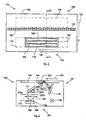
- the Fig. 1 represents a top view of a state-of-the-art scroll scanner 100 and the Fig. 2 represents a section of the scroll scanner 100 along the line II-II of the Fig. 1 .
- each light beam substantially takes the form of a succession of cones and the path of the luminous flux is more particularly represented by the path of its mean radius.
- a state-of-the-art scrolling scanner 100 comprises a window 108 on which a sheet 204, a lighting device 102, a focusing device 150 and an optical capture device or detection module 160.
- the sheet 204 is pressed against the pane 108 by roll-type pressing means and is driven in the direction of the arrow 180 by said pressing means.
- On the sheet 204 are printed gray level or color elements which are arranged on a uniform background or not.
- the lighting device 102 consists of a light-emitting diode array 104.
- the illumination device 102 emits a light flux 202 of white light which passes through the glass 108 to illuminate the sheet 204 to be scanned and which is reflected and diffused by the sheet 204.
- the optical capture device or detection module 160 comprises a sensor of the type CCD sensor 164 ("Charge Coupled Device"), CMOS (Complementary metal oxide semiconductor) or equivalent.
- the CCD sensor 164 consists of three rows 166, 168 and 170, each consisting of a plurality of sensitive elements, each delivering an electrical energy proportional to the intensity of the luminous flux that it receives.
- Each row 166, 168, 170 is sensitive in a spectral band different from the two others, called spectral band analysis band, each spectral band centered around a specific wavelength ⁇ 1 , ⁇ 2 , ⁇ 3 these wavelengths constituting the peak of sensitivity of each row.
- the three rows 166, 168 and 170 are arranged parallel to an axis 190. Each sensitive element of one of the rows is aligned with a sensitive element of each of the other two rows, so that these three sensing elements thus aligned form a column.
- the focusing device 150 is provided to form the image of a line of the sheet 204 on the optical capture device or detection module 160 and, in particular, to focus, on each of the rows 166, 168, 170, a part of the luminous flux reflected by said sheet 204, forming the image of three parallel lines of the sheet 204 on these three rows 166, 168 and 170.
- the lighting device 102 emits a light flux 202 whose spectrum covers said three spectral bands for analyzing the rows 166, 168 and 170.
- These wavelength values correspond to the reference wavelengths for which the characteristics of the optical materials (in particular, the refractive index) are known, knowing that the errors introduced by these approximations are quite negligible and without affecting the operation of the present invention.
- each line is illuminated by the incident luminous flux 202 and its image is successively focused on the three rows 166, 168 and 170 of the CCD sensor 164.
- the complete reading of a line is delayed in the time since it is necessary to wait for the passage of the image of said line on each of the rows 166, 168 and 170.
- each line of the sheet 204 is successively analyzed by three sensitive elements having a different spectral sensitivity but which are aligned on the same column.
- the lighting device 102 illuminates the sheet with the incident luminous flux 202 and the focusing system 150 forms the image, in each of said analysis strips, of three different lines of the sheet 204 on each of the three rows.
- 166, 168 and 170 this focusing being represented, for each of these spectral bands, by their mean radii 202a, 202b and 202c.
- Each row 166, 168, 170 is thus provided to receive one of the streams 202a, 202b and 202c.
- the focusing device 150 comprises, for example, a first mirror 106, a second mirror 110 and a lens 162.
- Each secondary flux 202a, 202b, 202c is reflected on the sheet 204, then on the first mirror 106, then on the second mirror 110, then through the lens 162 to be focused towards the optical capture device or detection module 160.
- This representation is a possible configuration but others may exist (for example, it is possible to replace the lens 162 using mirrors 106 and 110 having optical power and to achieve this focusing function).
- the various elements constituting the scroll scanner 100 are adjusted so that a secondary flow 202a, 202b, 202c focuses on each of the rows 166, 168 and 170.
- a scroll scanner 100 has a high image acquisition rate of the sheet 204 because no scrolling scanner element 100 is movable, so it is not necessary to reset the scroll scanner 100 between two consecutive 204 leaves. Unlike a flatbed scanner which requires the placement of the sheet on the glass and then the displacement of the focusing device and the optical capture device or detection module and finally the removal of the sheet and the repositioning of the focusing device and the device optical capture or detection module.
- Some applications require a high resolution that is difficult to find on prior art scroll scanners, except to use a scroll scanner with a very high price.
- biometric data sheets fingerprints, iris, .
- the cost of the scanners used is as low as possible and the speed of document processing is as fast as possible, the goal being to handle as many documents as possible in a minimum of time and space, for as little cost as possible. This is possible with existing scanners to date if their resolution can be improved by a typical factor of two to three in resolution.
- the document DE-A-198 35 348 discloses a scanner whose CCD sensor is modified representing a significant additional cost compared to an unmodified scanner.
- the document EP-A-1,528,814 discloses a video image capturing device that provides for an increase in resolution by using a prism.
- the introduction of a prism induces a substantial change in the direction of propagation of the beams by an order of magnitude greater than the spectral separation effect thereof. This therefore induces a significant change in the architecture of the capture device, the sensor is no longer parallel to the focus lens.
- An object of the present invention is to provide a scroll scanner whose resolution in the direction orthogonal to the direction of movement of the sheet is increased and which does not have the disadvantages of the state of the art and which, in particular, allows to increase the resolution of a scroll scanner in the direction orthogonal to the direction of movement of the sheet at a low cost and avoiding the increase in the time required to scan said sheet.
- the senor comprises three rows and with respect to the first offset flow, the second offset flow is shifted by about one third of sensitive element, and the third shifted flow is shifted by about two thirds of sensitive element.
- the scroll scanner comprises a band pass filter for said spectral bands.
- the spectral shift device consists of an optical blade inclined with respect to the plane of the sensor.
- the spectral shift device consists of an optical plate on one of the faces of which is made a succession of microgrooves with prismatic section, whose axis is oriented perpendicular to the direction of deflection sought after, called "microprisms" in the rest of the document.
- the other face of the optical plate carrying the succession of microprisms is in contact with the sensor.
- each microprism is disposed over an integer number of sensitive elements and only whole sensitive elements.
- the spectral shift device consists of a diffractive element placed at a distance from the sensor.
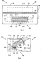
- the Fig. 3 is a top view of a scroll scanner 300 according to the invention which comprises a window 108 on which scroll a sheet 204, a lighting device 102, a focusing device 150 and an optical offset device or detection module 360.
- the scroll scanner 300 of the invention and, in particular, the device offset optical or detection module 360 comprises a non-prismatic spectral shift device 305 provided for shifting each part of the focused flux parallel to the rows 166, 168, 170, the shift ⁇ 1 , ⁇ 2 being different for each part of the focused flux , i.e., for each row 166, 168, 170.
- the scroll scanner 300 is such that the optical offset device or detection module 360 comprises the non-prismatic spectral shift device 305 intended to shift, each part of the light flux thus focused, parallel to said rows 166, 168, 170, the offset ⁇ 1 , ⁇ 2 being different for each row 166, 168, 170.
- the shift ⁇ 1 , ⁇ 2 of a flux is counted positively in the direction of the axis 190 and negatively in the opposite direction, that is to say that the shift ⁇ 1, ⁇ 2 of a flow is counted positively when this flow is displaced in the direction of the axis 190 and negatively when this flow is moved in the opposite direction.
- Two offsets ⁇ 1 , ⁇ 2 are different if they are of opposite signs or if, by being of the same sign, the values of their absolute amplitudes are different. The goal is to shift the different luminous fluxes relative to each other so that none of them is aligned with one another.
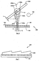
- the spectral shift device 305 is in the form of an inclined optical plate of thickness ⁇ , as is better seen on the Fig. 5 which represents a section of the optical offset device 360 along line VV of the Fig. 4 .
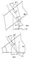
- the spectral shift device 305 is in the form of an optical plate 705 on one of the faces of which is made a succession of microgrooves with prismatic section, whose axis is oriented perpendicular to the desired direction of deflection, called "microprisms", as is better seen on the Fig. 7 .
- the spectral shift device 305 may be made of glass or a plastic material. Examples include the following materials BK7, SF11, Plexiglas, Polycarbonate or others, as long as the chosen material has the desired characteristics: transparency in the operating spectrum of the sensor 164, "optical" quality of the material, suitable chromatic dispersion.
- the spectral shifter 305 is placed between the lens 162 and the CCD 164.
- the secondary streams 202a, 202b and 202c pass through the spectral shifter 305 before focusing on the CCD 164.
- the spectral shifter 305 is placed as close as possible to the CCD sensor in order to limit the generated aberrations.
- the optical offset device or detection module 360 thus comprises the CCD 1.64 sensor and the spectral shift device 305.
- the time required to scan a sheet 204 is identical to the time required for a scroll scanner 100 of the state of the art since no moving element has been introduced into the scroll scanner 100 of the invention.
- the optical plate 305 is inclined at an angle ⁇ relative to the horizontal, that is to say with respect to the plane of the CCD sensor 164.
- Each secondary stream 202a, 202b, 202c passes through the optical plate 305 and leaves it in the form of an offset secondary flux respectively referenced 302a, 302b, 302c.
- the offset is continuous as a function of the wavelength and it is the average position of the image corresponding to the spectral band considered is represented here.
- the first offset secondary flux 302a focuses on the row 166
- the second offset secondary flux 302b focuses on the row 168 with a shift ⁇ 1 by relative to the first offset secondary flow 302a and this in the direction orthogonal to the direction of movement 180 of the sheet 204, that is to say, parallel to the orientation of the rows 166, 168 and 170 of sensitive elements of the CCD sensor 164.
- the third shifted secondary stream 302c focuses on the row 170 with an offset ⁇ 2 relative to the first shifted secondary stream 302a and this in the direction orthogonal to the direction of displacement 180 of the sheet 204.
- the offset ⁇ 1 , ( ⁇ 2 - ⁇ 1 ) between two consecutive offset second fluxes 302a-302b, 302b-302c is substantially equal to one third of the dimension in the offset direction of a sensitive element, that is, that is to say, one third of the pixel dimension of the CCD sensor 164 parallel to the axis 190.
- each secondary stream 202a, 202b, 202c makes it possible to increase the resolution in the direction orthogonal to the direction of displacement 180 of the sheet 204.
- the Fig. 6 allows to calculate the shift ⁇ specific to each wavelength, that is to say between the secondary stream 202 and the corresponding shifted secondary flux 302.
- the shift ⁇ 1 , ( ⁇ 2 - ⁇ 1 ) between two consecutive offset shifts 302a-302b, 302b-302c is then calculated by difference between the shifts ⁇ specific to the corresponding wavelengths.
- the angle ⁇ ' is dependent on the wavelength of the secondary flow 202 and the material constituting the optical blade 305.
- each secondary flux 202a, 202b, 202c which is taken into account is preferably that which is centered on the sensitivity peak of the row 166, 168, 170 considered.
- the shift ⁇ 1 corresponds substantially to one-third of 9.325 ⁇ m ( ie: 3.108 ⁇ m) in the opposite direction to the axis 190
- the offset ⁇ 2 substantially corresponds to two-thirds of 9.325 ⁇ m (ie: 6.217 ⁇ m) in the opposite direction to the axis 190.
- the shift ⁇ 1 approaches 3.1 ⁇ m and that the offset ⁇ 2 approaches 6.2 ⁇ m. But even if the offsets ⁇ 1 and ⁇ 2 deviate from these values, the invention can operate as long as the offsets are significant with respect to the dimensions of the sensitive elements.
- the inclination remains less than 10 °.
- excessive shifts ⁇ 1 and ⁇ 2 can be reduced by reducing the thickness and / or the inclination of the optical blade 305, or the choice of a less dispersive material .
- the offsets ⁇ 1 and ⁇ 2 are too small, they can be increased by increasing the thickness and / or the inclination of the optical blade 305, or the choice of a more dispersive material.
- the optical plate must be relatively thick so that the chromatic dispersion effect is sufficient to obtain the desired shift.
- the thickness to length ratio of the blade must be greater than one twentieth. To minimize other optical aberrations caused by the blade, this ratio should be less than one-ninth
- the face of the optical blade 705 which does not carry the succession of microprisms rests on the CCD sensor 164, that is to say that this face of the optical blade 705 is in contact with the sensor 164.
- Each microprism here has a triangular section whose one side has an angle ⁇ relative to the horizontal, that is to say with respect to the plane of the CCD sensor 164, and whose another side is vertical, that is to say orthogonal to the plane of the sensor 164.
- each vertical side of the microprisms is aligned with the boundary between two sensitive elements.
- each microprism must be disposed over an integer number of sensitive elements and only whole sensitive elements.
- each secondary stream 202a, 202b, 202e passes through the microprisms and the optical plate 705 and leaves in the form of a shifted secondary flux that activates the sensitive elements of the CCD sensor 164 .
- the first shifted secondary stream and the second shifted secondary stream are shifted by ⁇ 1
- the shifted third shunt and the shifted first shunt are shifted by ⁇ 2 .
- the Fig. 8 allows to calculate the shift ⁇ specific to each wavelength, that is to say between the secondary stream 202 and the corresponding shifted secondary flux 302.
- the shift ⁇ 1 , ( ⁇ 2 - ⁇ 1 ) between two consecutive offset shifts is then calculated by difference between the shifts ⁇ specific to the corresponding wavelengths.
- the method for determining the physical characteristics of the microprisms and the optical blade 705 is in accordance with that described for the first embodiment, except that the inclination no longer represents the inclination of the optical blade but the angle of each microprism.
- each scanned line of the sheet 204 is decomposed into three secondary streams 202a, 202b, 202c which are each offset in the form of a stream offset secondary 302a, 302b, 302c.
- Each offset secondary flux 302a, 302b, 302e comes to excite the sensitive elements of one of the rows 166, 168, 170 of the CCD sensor 164.
- the image of the scanned line of the sheet 204 is thus formed successively on each row 166, 168, 170 shifted by about one third of a pixel on each of these rows 166, 168, 170.
- these three primary images of the sheet can then be recombined by calculating the sub-pixel characteristics, which are smaller than the sensor pixels (typically 3 subpixels per pixel in the example described, these sub-pixels having a size equal to one third of a pixel) so as to obtain the desired resolution increase.
- these methods are known to the skilled person. Examples include patents JP2002199248 , EP1079330 or EP1226508 as regards the geometry of each sub-pixel calculated or the patents EP0221111 or EP1157538 if we consider rather the color aspect of the calculated subpixel.
- the offset offset shifts 302a, 302b, 302c therefore makes it possible to increase the resolution of the scrolling scanner 300 in the direction orthogonal to the direction of movement 180 of the sheet 204.
- the setting up of the non-prismatic spectral shifting device 305 can to be easily performed on a scrolling scanner of the state of the art, that is to say that the increase of the resolution of the scrolling scanner 100 of the state of the art is easily achieved by adding the non-prismatic spectral shift device 305 and this allows the realization of a scroll scanner with a high resolution and for a reduced cost.
- non-prismatic spectral shift device 305 makes it possible to increase the resolution of the scrolling scanner 300 without inducing any distortion or annoying optical aberrations, since it goes against the effect of increasing the resolution. by a noticeable degradation in the quality of the images formed, as would occur in the case of the use of a convergent ray prism (i.e., between the focusing lens and the sensor).
- the resolution is here multiplied by 3 because of the shift of a third of a pixel.
- This value can be obtained by modifying the physical characteristics of the shifter such as, for example, its dimensions, its material, its inclination, etc.
- the optimization of the result is thus obtained when, with respect to the first shifted flux 302a, the second shifted flux 302b is shifted by about one third of sensitive element, and the third shifted flux 302c is shifted by about two thirds of sensitive element, that is to say respectively a third pixel and two thirds of a pixel.
- the approximation method may, for example, assign to each new sensitive sub-element a value generated from the averaged color between the value recorded by the corresponding sensitive element and that of its neighbors, possibly weighted by the average of the three components so as to take into account the chromatic value of the scanned elements, with respect to the rest of the image.
- assign to each new sensitive sub-element a value generated from the averaged color between the value recorded by the corresponding sensitive element and that of its neighbors, possibly weighted by the average of the three components so as to take into account the chromatic value of the scanned elements, with respect to the rest of the image.
- the spectral shift device may take the form of a diffractive element, for example a diffraction grating. This must be arranged at a certain distance from the CCD sensor so that the deviation generated for each stream and which is proportional to this distance, allows to create a shift close to what is sought.
- a diffractive element for example a diffraction grating. This must be arranged at a certain distance from the CCD sensor so that the deviation generated for each stream and which is proportional to this distance, allows to create a shift close to what is sought.
- the mirrors may be mirrors having optical power, and the setting up of the lens is then no longer necessary.
- a bandpass filter for said spectral bands (in this case 3 bands) can be set up on the optical path upstream of the sensor, this filter then making it possible to limit the luminous flux around sensor sensitivity peaks and improve the images produced in each spectral band by limiting the chromatic aberrations of the device.
- the offset generated between two consecutive rows by the spectral shift device is close to the ratio of the width of a sensitive element to the number of rows.
- the sensor may have four rows, three of which are dedicated to colors and one of which is dedicated to gray levels, the offset is then preferably equal to one quarter of the width of a sensitive element.
- the sensor may have two rows, one being dedicated to the visible spectrum and the other to the infrared spectrum, the offset is then preferably equal to half the width of a sensitive element.
Landscapes
- Engineering & Computer Science (AREA)
- Multimedia (AREA)
- Signal Processing (AREA)
- Facsimile Scanning Arrangements (AREA)
- Image Input (AREA)
Claims (8)
- Durchzugscanner (300), aufweisend:- eine Beleuchtungsvorrichtung (102), vorgesehen zum Abgeben eines Lichtstroms mit mehreren Spektralbändern (λ1, λ2, λ3), der dazu bestimmt ist, ein zu scannendes Blatt (204) zu beleuchten,- eine Fokussierungsvorrichtung (150), und- ein Erfassungsmodul (360), das einen Aufnehmer (164) aufweist, der eine Vielzahl von Reihen (166, 168, 170) von Sensorelementen aufweist, wobei jedes Sensorelement dafür vorgesehen ist, eine zu der Stärke des empfangenen Lichtstroms proportionale elektrische Energie zu liefern, und wobei jede Reihe dafür vorgesehen ist, ihren Empfindlichkeitsspitzenwert für eines der Spektralbänder darzustellen, wobei jedes Sensorelement einer der Reihen mit einem Sensorelement jeder der zwei anderen Reihen so ausgerichtet ist, dass diese drei so ausgerichteten Sensorelemente eine Spalte bilden,wobei die Fokussierungsvorrichtung dafür vorgesehen ist, auf jede der Reihen einen Teil des Lichtstroms zu fokussieren, der von dem Blatt reflektiert wird,
wobei der Durchzugscanner (300) dadurch gekennzeichnet ist, dass das Erfassungsmodul (360) eine feststehende optische Spektralverschiebungsvorrichtung (305, 705) aufweist, die dafür vorgesehen ist, jeden Teil des so fokussierten Lichtstroms parallel zu den Reihen (166, 168, 170) zu verschieben, wobei die Verschiebung (δ1, δ2) für jede Reihe (166, 168, 170) verschieden ist. - Durchzugscanner (300) nach Anspruch 1, dadurch gekennzeichnet, dass die Verschiebung, die zwischen zwei aufeinanderfolgenden Reihen durch die Spektralverschiebungseinheit (305, 1205) erzeugt wird, dem Verhältnis der Breite eines Sensorelements zu der Anzahl von Reihen (166, 168, 170) benachbart ist.
- Durchzugscanner (300) nach einem der Ansprüche 1 oder 2, dadurch gekennzeichnet, dass der Aufnehmer drei Reihen (166, 168, 170) aufweist und dadurch, dass in Bezug auf den ersten verschobenen Strom (302a) der zweite verschobene Strom (302b) um ungefähr ein Drittel eines Sensorelements verschoben wird und der dritte verschobene Strom (302c) um ungefähr zwei Drittel eines Sensorelements verschoben wird.
- Durchzugscanner (300) nach einem der Ansprüche 1 bis 3, dadurch gekennzeichnet, dass er ein Bandpassfilter für die Spektralbänder aufweist.
- Durchzugscanner (300) nach einem der Ansprüche 1 bis 4, dadurch gekennzeichnet, dass die Spektralverschiebungsvorrichtung aus einer optischen Platte (305) gebildet wird, die in Bezug auf die Ebene des Aufnehmers (164) um (α) geneigt ist.
- Durchzugscanner (300) nach einem der Ansprüche 1 bis 4, dadurch gekennzeichnet, dass die Spektralverschiebungsvorrichtung aus einer optischen Platte (705) gebildet ist, wobei auf einer ihrer Seiten eine Abfolge von Mikroprismen ausgeführt ist, und dadurch, dass die andere Seite der die Abfolge von Mikroprismen tragenden optischen Platte (705) in Kontakt mit dem Aufnehmer (164) steht.
- Durchzugscanner (300) nach Anspruch 6, dadurch gekennzeichnet, dass jedes Mikroprisma über einer ganzen Zahl von Sensorelementen und ausschließlich ganzen Sensorelementen angeordnet ist.
- Durchzugscanner (300) nach einem der Ansprüche 1 bis 4, dadurch gekennzeichnet, dass die Spektralverschiebungsvorrichtung aus einem Diffraktionselement gebildet ist, das im Abstand zum Aufnehmer (164) platziert ist.
Applications Claiming Priority (1)
| Application Number | Priority Date | Filing Date | Title |
|---|---|---|---|
| FR0608728A FR2906959B1 (fr) | 2006-10-04 | 2006-10-04 | Scanner a defilement. |
Publications (2)
| Publication Number | Publication Date |
|---|---|
| EP1909480A1 EP1909480A1 (de) | 2008-04-09 |
| EP1909480B1 true EP1909480B1 (de) | 2014-09-17 |
Family
ID=38008207
Family Applications (1)
| Application Number | Title | Priority Date | Filing Date |
|---|---|---|---|
| EP07019393.3A Not-in-force EP1909480B1 (de) | 2006-10-04 | 2007-10-03 | Scanner mit Scrollfunktion |
Country Status (4)
| Country | Link |
|---|---|
| US (1) | US8149481B2 (de) |
| EP (1) | EP1909480B1 (de) |
| CA (1) | CA2605637C (de) |
| FR (1) | FR2906959B1 (de) |
Families Citing this family (1)
| Publication number | Priority date | Publication date | Assignee | Title |
|---|---|---|---|---|
| US8559063B1 (en) | 2012-11-30 | 2013-10-15 | Atiz Innovation Co., Ltd. | Document scanning and visualization system using a mobile device |
Family Cites Families (11)
| Publication number | Priority date | Publication date | Assignee | Title |
|---|---|---|---|---|
| JPH0620221B2 (ja) * | 1987-07-15 | 1994-03-16 | 大日本スクリ−ン製造株式会社 | 読取りタイミングを相対的にずらせた画像読取り装置 |
| US5414534A (en) * | 1992-12-02 | 1995-05-09 | Vidar Systems Corporation | Apparatus for mechanically adjusting the image on CCD arrays in a scanning apparatus |
| US5453611A (en) * | 1993-01-01 | 1995-09-26 | Canon Kabushiki Kaisha | Solid-state image pickup device with a plurality of photoelectric conversion elements on a common semiconductor chip |
| JP3471156B2 (ja) * | 1995-05-30 | 2003-11-25 | シャープ株式会社 | イメージシフト機構および撮像装置 |
| US6567189B1 (en) * | 1998-01-23 | 2003-05-20 | Canon Kabushiki Kaisha | Image reading apparatus |
| DE19835348A1 (de) * | 1998-08-05 | 2000-02-10 | Heidelberger Druckmasch Ag | Vorrichtung zur Abtastung von Vorlagen |
| JP3191794B2 (ja) * | 1999-02-05 | 2001-07-23 | 富士ゼロックス株式会社 | 画像読取装置 |
| JP2001111774A (ja) * | 1999-10-06 | 2001-04-20 | Canon Inc | カラー画像読取装置 |
| US7961235B2 (en) * | 2003-10-31 | 2011-06-14 | Hewlett-Packard Development Company, L.P. | Imaging apparatuses, image data processing methods, and articles of manufacture |
| JP4436859B2 (ja) * | 2007-08-09 | 2010-03-24 | シャープ株式会社 | 画像読取装置 |
| JP2009171561A (ja) * | 2007-12-21 | 2009-07-30 | Canon Inc | 画像処理装置及び画像処理方法 |
-
2006
- 2006-10-04 FR FR0608728A patent/FR2906959B1/fr not_active Expired - Fee Related
-
2007
- 2007-10-03 EP EP07019393.3A patent/EP1909480B1/de not_active Not-in-force
- 2007-10-04 US US11/906,834 patent/US8149481B2/en not_active Expired - Fee Related
- 2007-10-04 CA CA2605637A patent/CA2605637C/en active Active
Also Published As
| Publication number | Publication date |
|---|---|
| US8149481B2 (en) | 2012-04-03 |
| FR2906959B1 (fr) | 2011-05-06 |
| CA2605637C (en) | 2017-05-23 |
| FR2906959A1 (fr) | 2008-04-11 |
| CA2605637A1 (en) | 2008-04-04 |
| EP1909480A1 (de) | 2008-04-09 |
| US20080088890A1 (en) | 2008-04-17 |
Similar Documents
| Publication | Publication Date | Title |
|---|---|---|
| EP3132237B9 (de) | Vorrichtung und verfahren für lichtrastermikroskopie | |
| EP1482288B1 (de) | Statisches Fouriertransformspektrometer | |
| EP3376544A1 (de) | Optische bildanzeigevorrichtung | |
| EP1084379B1 (de) | Optoelektronische Formerfassung durch chromatische Kodierung mit Beleuchtungsebenen | |
| EP2852815A1 (de) | Chromatischer wandler für altimetrie | |
| EP4251961A1 (de) | Multispektraler bildgeber mit vergrössertem spektralbereich | |
| EP1955101A1 (de) | Rasterabbildungseinrichtung auf fluoreszenzbasis | |
| EP1193468B1 (de) | Optisches Verfahren zur Messung der Form eines Profils und Anwendung dieses Verfahrens für das Innenprofil einer Brillenfassung | |
| CA2643371A1 (fr) | Biodetecteur sans contact | |
| EP1909480B1 (de) | Scanner mit Scrollfunktion | |
| EP2198337A2 (de) | Abbildungssystem mit wellenfrontmodifikation und verfahren zur erhöhung der feldtiefe eines abbildungssystems | |
| FR2541783A1 (fr) | Systeme d'analyse optique a miroirs situes dans un plan d'un disque rotatif | |
| FR2877433A1 (fr) | Procede et dispositif pour la saisie sans contact des proprietes thermiques de la surface d'un objet | |
| FR2749944A1 (fr) | Appareil de lecture d'images | |
| FR2951823A1 (fr) | Procede et dispositif de mesure spectrometrique d'un flux de matiere se deplacant en direction longitudinale | |
| EP4345446B1 (de) | Multispektrale reflexionsbildgebungsvorrichtung | |
| FR2610421A1 (fr) | Dispositif de deflexion de faisceau et imprimante a faisceau laser l'utilisant | |
| EP1141668B1 (de) | Vorrichtung zum spektralen abblenden in einem optischen bildsensor | |
| FR2480462A1 (fr) | Dispositif de lecture electro-optique des lignes d'un document et ensemble comportant un tel dispositif | |
| FR3046276A1 (fr) | Procede pour obtenir une image fusionnee d'une empreinte papillaire | |
| EP4695587A1 (de) | Optisches spektrometer und ramanmikroskop mit einem solchen spektrometer | |
| FR2835611A1 (fr) | Procede et dispositif pour la detection de defauts tels que souillures, rayures, poussieres sur un film notamment en vue d'effectuer la correction de ces defauts lors de la numerisation d'un film | |
| FR3096454A1 (fr) | Installation d’éclairage optique d’un échantillon et installation de l’analyse de l’échantillon et procédé de gestion de l’installation d’analyse optique | |
| WO2017025676A1 (fr) | Appareil de numérisation | |
| FR2740930A1 (fr) | Procede d'acquisition des images electroniques d'au moins deux scenes fournies par une pluralite d'elements photosensibles |
Legal Events
| Date | Code | Title | Description |
|---|---|---|---|
| PUAI | Public reference made under article 153(3) epc to a published international application that has entered the european phase |
Free format text: ORIGINAL CODE: 0009012 |
|
| AK | Designated contracting states |
Kind code of ref document: A1 Designated state(s): AT BE BG CH CY CZ DE DK EE ES FI FR GB GR HU IE IS IT LI LT LU LV MC MT NL PL PT RO SE SI SK TR |
|
| AX | Request for extension of the european patent |
Extension state: AL BA HR MK RS |
|
| 17P | Request for examination filed |
Effective date: 20081006 |
|
| AKX | Designation fees paid |
Designated state(s): AT BE BG CH CY CZ DE DK EE ES FI FR GB GR HU IE IS IT LI LT LU LV MC MT NL PL PT RO SE SI SK TR |
|
| RAP1 | Party data changed (applicant data changed or rights of an application transferred) |
Owner name: MORPHO |
|
| 17Q | First examination report despatched |
Effective date: 20110502 |
|
| RAP1 | Party data changed (applicant data changed or rights of an application transferred) |
Owner name: MORPHO |
|
| GRAP | Despatch of communication of intention to grant a patent |
Free format text: ORIGINAL CODE: EPIDOSNIGR1 |
|
| INTG | Intention to grant announced |
Effective date: 20140409 |
|
| GRAS | Grant fee paid |
Free format text: ORIGINAL CODE: EPIDOSNIGR3 |
|
| GRAA | (expected) grant |
Free format text: ORIGINAL CODE: 0009210 |
|
| AK | Designated contracting states |
Kind code of ref document: B1 Designated state(s): AT BE BG CH CY CZ DE DK EE ES FI FR GB GR HU IE IS IT LI LT LU LV MC MT NL PL PT RO SE SI SK TR |
|
| REG | Reference to a national code |
Ref country code: GB Ref legal event code: FG4D Free format text: NOT ENGLISH |
|
| REG | Reference to a national code |
Ref country code: CH Ref legal event code: EP |
|
| REG | Reference to a national code |
Ref country code: IE Ref legal event code: FG4D Free format text: LANGUAGE OF EP DOCUMENT: FRENCH |
|
| REG | Reference to a national code |
Ref country code: AT Ref legal event code: REF Ref document number: 688142 Country of ref document: AT Kind code of ref document: T Effective date: 20141015 |
|
| REG | Reference to a national code |
Ref country code: DE Ref legal event code: R096 Ref document number: 602007038559 Country of ref document: DE Effective date: 20141030 |
|
| PG25 | Lapsed in a contracting state [announced via postgrant information from national office to epo] |
Ref country code: FI Free format text: LAPSE BECAUSE OF FAILURE TO SUBMIT A TRANSLATION OF THE DESCRIPTION OR TO PAY THE FEE WITHIN THE PRESCRIBED TIME-LIMIT Effective date: 20140917 Ref country code: GR Free format text: LAPSE BECAUSE OF FAILURE TO SUBMIT A TRANSLATION OF THE DESCRIPTION OR TO PAY THE FEE WITHIN THE PRESCRIBED TIME-LIMIT Effective date: 20141218 Ref country code: SE Free format text: LAPSE BECAUSE OF FAILURE TO SUBMIT A TRANSLATION OF THE DESCRIPTION OR TO PAY THE FEE WITHIN THE PRESCRIBED TIME-LIMIT Effective date: 20140917 Ref country code: LT Free format text: LAPSE BECAUSE OF FAILURE TO SUBMIT A TRANSLATION OF THE DESCRIPTION OR TO PAY THE FEE WITHIN THE PRESCRIBED TIME-LIMIT Effective date: 20140917 |
|
| REG | Reference to a national code |
Ref country code: NL Ref legal event code: VDEP Effective date: 20140917 |
|
| REG | Reference to a national code |
Ref country code: LT Ref legal event code: MG4D |
|
| PG25 | Lapsed in a contracting state [announced via postgrant information from national office to epo] |
Ref country code: CY Free format text: LAPSE BECAUSE OF FAILURE TO SUBMIT A TRANSLATION OF THE DESCRIPTION OR TO PAY THE FEE WITHIN THE PRESCRIBED TIME-LIMIT Effective date: 20140917 Ref country code: LV Free format text: LAPSE BECAUSE OF FAILURE TO SUBMIT A TRANSLATION OF THE DESCRIPTION OR TO PAY THE FEE WITHIN THE PRESCRIBED TIME-LIMIT Effective date: 20140917 |
|
| REG | Reference to a national code |
Ref country code: AT Ref legal event code: MK05 Ref document number: 688142 Country of ref document: AT Kind code of ref document: T Effective date: 20140917 |
|
| PG25 | Lapsed in a contracting state [announced via postgrant information from national office to epo] |
Ref country code: NL Free format text: LAPSE BECAUSE OF FAILURE TO SUBMIT A TRANSLATION OF THE DESCRIPTION OR TO PAY THE FEE WITHIN THE PRESCRIBED TIME-LIMIT Effective date: 20140917 |
|
| PG25 | Lapsed in a contracting state [announced via postgrant information from national office to epo] |
Ref country code: IS Free format text: LAPSE BECAUSE OF FAILURE TO SUBMIT A TRANSLATION OF THE DESCRIPTION OR TO PAY THE FEE WITHIN THE PRESCRIBED TIME-LIMIT Effective date: 20150117 Ref country code: PT Free format text: LAPSE BECAUSE OF FAILURE TO SUBMIT A TRANSLATION OF THE DESCRIPTION OR TO PAY THE FEE WITHIN THE PRESCRIBED TIME-LIMIT Effective date: 20150119 Ref country code: ES Free format text: LAPSE BECAUSE OF FAILURE TO SUBMIT A TRANSLATION OF THE DESCRIPTION OR TO PAY THE FEE WITHIN THE PRESCRIBED TIME-LIMIT Effective date: 20140917 Ref country code: SK Free format text: LAPSE BECAUSE OF FAILURE TO SUBMIT A TRANSLATION OF THE DESCRIPTION OR TO PAY THE FEE WITHIN THE PRESCRIBED TIME-LIMIT Effective date: 20140917 Ref country code: CZ Free format text: LAPSE BECAUSE OF FAILURE TO SUBMIT A TRANSLATION OF THE DESCRIPTION OR TO PAY THE FEE WITHIN THE PRESCRIBED TIME-LIMIT Effective date: 20140917 Ref country code: EE Free format text: LAPSE BECAUSE OF FAILURE TO SUBMIT A TRANSLATION OF THE DESCRIPTION OR TO PAY THE FEE WITHIN THE PRESCRIBED TIME-LIMIT Effective date: 20140917 Ref country code: RO Free format text: LAPSE BECAUSE OF FAILURE TO SUBMIT A TRANSLATION OF THE DESCRIPTION OR TO PAY THE FEE WITHIN THE PRESCRIBED TIME-LIMIT Effective date: 20140917 |
|
| REG | Reference to a national code |
Ref country code: DE Ref legal event code: R119 Ref document number: 602007038559 Country of ref document: DE |
|
| PG25 | Lapsed in a contracting state [announced via postgrant information from national office to epo] |
Ref country code: AT Free format text: LAPSE BECAUSE OF FAILURE TO SUBMIT A TRANSLATION OF THE DESCRIPTION OR TO PAY THE FEE WITHIN THE PRESCRIBED TIME-LIMIT Effective date: 20140917 Ref country code: PL Free format text: LAPSE BECAUSE OF FAILURE TO SUBMIT A TRANSLATION OF THE DESCRIPTION OR TO PAY THE FEE WITHIN THE PRESCRIBED TIME-LIMIT Effective date: 20140917 |
|
| REG | Reference to a national code |
Ref country code: CH Ref legal event code: PL |
|
| PG25 | Lapsed in a contracting state [announced via postgrant information from national office to epo] |
Ref country code: MC Free format text: LAPSE BECAUSE OF FAILURE TO SUBMIT A TRANSLATION OF THE DESCRIPTION OR TO PAY THE FEE WITHIN THE PRESCRIBED TIME-LIMIT Effective date: 20140917 Ref country code: BE Free format text: LAPSE BECAUSE OF NON-PAYMENT OF DUE FEES Effective date: 20141031 |
|
| PLBE | No opposition filed within time limit |
Free format text: ORIGINAL CODE: 0009261 |
|
| STAA | Information on the status of an ep patent application or granted ep patent |
Free format text: STATUS: NO OPPOSITION FILED WITHIN TIME LIMIT |
|
| REG | Reference to a national code |
Ref country code: IE Ref legal event code: MM4A |
|
| PG25 | Lapsed in a contracting state [announced via postgrant information from national office to epo] |
Ref country code: CH Free format text: LAPSE BECAUSE OF NON-PAYMENT OF DUE FEES Effective date: 20141031 Ref country code: DK Free format text: LAPSE BECAUSE OF FAILURE TO SUBMIT A TRANSLATION OF THE DESCRIPTION OR TO PAY THE FEE WITHIN THE PRESCRIBED TIME-LIMIT Effective date: 20140917 Ref country code: LI Free format text: LAPSE BECAUSE OF NON-PAYMENT OF DUE FEES Effective date: 20141031 Ref country code: DE Free format text: LAPSE BECAUSE OF NON-PAYMENT OF DUE FEES Effective date: 20150501 |
|
| REG | Reference to a national code |
Ref country code: FR Ref legal event code: ST Effective date: 20150630 |
|
| 26N | No opposition filed |
Effective date: 20150618 |
|
| GBPC | Gb: european patent ceased through non-payment of renewal fee |
Effective date: 20141217 |
|
| PG25 | Lapsed in a contracting state [announced via postgrant information from national office to epo] |
Ref country code: IT Free format text: LAPSE BECAUSE OF FAILURE TO SUBMIT A TRANSLATION OF THE DESCRIPTION OR TO PAY THE FEE WITHIN THE PRESCRIBED TIME-LIMIT Effective date: 20140917 Ref country code: FR Free format text: LAPSE BECAUSE OF NON-PAYMENT OF DUE FEES Effective date: 20141117 |
|
| PG25 | Lapsed in a contracting state [announced via postgrant information from national office to epo] |
Ref country code: IE Free format text: LAPSE BECAUSE OF NON-PAYMENT OF DUE FEES Effective date: 20141003 Ref country code: GB Free format text: LAPSE BECAUSE OF NON-PAYMENT OF DUE FEES Effective date: 20141217 |
|
| PG25 | Lapsed in a contracting state [announced via postgrant information from national office to epo] |
Ref country code: SI Free format text: LAPSE BECAUSE OF FAILURE TO SUBMIT A TRANSLATION OF THE DESCRIPTION OR TO PAY THE FEE WITHIN THE PRESCRIBED TIME-LIMIT Effective date: 20140917 |
|
| PG25 | Lapsed in a contracting state [announced via postgrant information from national office to epo] |
Ref country code: BG Free format text: LAPSE BECAUSE OF FAILURE TO SUBMIT A TRANSLATION OF THE DESCRIPTION OR TO PAY THE FEE WITHIN THE PRESCRIBED TIME-LIMIT Effective date: 20140917 |
|
| PG25 | Lapsed in a contracting state [announced via postgrant information from national office to epo] |
Ref country code: MT Free format text: LAPSE BECAUSE OF FAILURE TO SUBMIT A TRANSLATION OF THE DESCRIPTION OR TO PAY THE FEE WITHIN THE PRESCRIBED TIME-LIMIT Effective date: 20140917 Ref country code: LU Free format text: LAPSE BECAUSE OF NON-PAYMENT OF DUE FEES Effective date: 20141003 Ref country code: TR Free format text: LAPSE BECAUSE OF FAILURE TO SUBMIT A TRANSLATION OF THE DESCRIPTION OR TO PAY THE FEE WITHIN THE PRESCRIBED TIME-LIMIT Effective date: 20140917 Ref country code: HU Free format text: LAPSE BECAUSE OF FAILURE TO SUBMIT A TRANSLATION OF THE DESCRIPTION OR TO PAY THE FEE WITHIN THE PRESCRIBED TIME-LIMIT; INVALID AB INITIO Effective date: 20071003 |