EP1909478A2 - Multifunktionelles Peripheriegerät - Google Patents
Multifunktionelles Peripheriegerät Download PDFInfo
- Publication number
- EP1909478A2 EP1909478A2 EP07110945A EP07110945A EP1909478A2 EP 1909478 A2 EP1909478 A2 EP 1909478A2 EP 07110945 A EP07110945 A EP 07110945A EP 07110945 A EP07110945 A EP 07110945A EP 1909478 A2 EP1909478 A2 EP 1909478A2
- Authority
- EP
- European Patent Office
- Prior art keywords
- unit
- printing
- printing unit
- scanning
- multifunction peripheral
- Prior art date
- Legal status (The legal status is an assumption and is not a legal conclusion. Google has not performed a legal analysis and makes no representation as to the accuracy of the status listed.)
- Withdrawn
Links
Images

Classifications
-
- H—ELECTRICITY
- H04—ELECTRIC COMMUNICATION TECHNIQUE
- H04N—PICTORIAL COMMUNICATION, e.g. TELEVISION
- H04N1/00—Scanning, transmission or reproduction of documents or the like, e.g. facsimile transmission; Details thereof
- H04N1/04—Scanning arrangements, i.e. arrangements for the displacement of active reading or reproducing elements relative to the original or reproducing medium, or vice versa
- H04N1/0461—Scanning arrangements, i.e. arrangements for the displacement of active reading or reproducing elements relative to the original or reproducing medium, or vice versa part of the apparatus being used in common for reading and reproducing
-
- H—ELECTRICITY
- H04—ELECTRIC COMMUNICATION TECHNIQUE
- H04N—PICTORIAL COMMUNICATION, e.g. TELEVISION
- H04N1/00—Scanning, transmission or reproduction of documents or the like, e.g. facsimile transmission; Details thereof
- H04N1/024—Details of scanning heads ; Means for illuminating the original
- H04N1/028—Details of scanning heads ; Means for illuminating the original for picture information pick-up
-
- H—ELECTRICITY
- H04—ELECTRIC COMMUNICATION TECHNIQUE
- H04N—PICTORIAL COMMUNICATION, e.g. TELEVISION
- H04N1/00—Scanning, transmission or reproduction of documents or the like, e.g. facsimile transmission; Details thereof
- H04N1/04—Scanning arrangements, i.e. arrangements for the displacement of active reading or reproducing elements relative to the original or reproducing medium, or vice versa
- H04N1/207—Simultaneous scanning of the original picture and the reproduced picture with a common scanning device
-
- H—ELECTRICITY
- H04—ELECTRIC COMMUNICATION TECHNIQUE
- H04N—PICTORIAL COMMUNICATION, e.g. TELEVISION
- H04N1/00—Scanning, transmission or reproduction of documents or the like, e.g. facsimile transmission; Details thereof
- H04N1/04—Scanning arrangements, i.e. arrangements for the displacement of active reading or reproducing elements relative to the original or reproducing medium, or vice versa
- H04N1/10—Scanning arrangements, i.e. arrangements for the displacement of active reading or reproducing elements relative to the original or reproducing medium, or vice versa using flat picture-bearing surfaces
- H04N1/1013—Scanning arrangements, i.e. arrangements for the displacement of active reading or reproducing elements relative to the original or reproducing medium, or vice versa using flat picture-bearing surfaces with sub-scanning by translatory movement of at least a part of the main-scanning components
- H04N1/1017—Scanning arrangements, i.e. arrangements for the displacement of active reading or reproducing elements relative to the original or reproducing medium, or vice versa using flat picture-bearing surfaces with sub-scanning by translatory movement of at least a part of the main-scanning components the main-scanning components remaining positionally invariant with respect to one another in the sub-scanning direction
-
- H—ELECTRICITY
- H04—ELECTRIC COMMUNICATION TECHNIQUE
- H04N—PICTORIAL COMMUNICATION, e.g. TELEVISION
- H04N1/00—Scanning, transmission or reproduction of documents or the like, e.g. facsimile transmission; Details thereof
- H04N1/04—Scanning arrangements, i.e. arrangements for the displacement of active reading or reproducing elements relative to the original or reproducing medium, or vice versa
- H04N1/19—Scanning arrangements, i.e. arrangements for the displacement of active reading or reproducing elements relative to the original or reproducing medium, or vice versa using multi-element arrays
- H04N1/191—Scanning arrangements, i.e. arrangements for the displacement of active reading or reproducing elements relative to the original or reproducing medium, or vice versa using multi-element arrays the array comprising a one-dimensional array, or a combination of one-dimensional arrays, or a substantially one-dimensional array, e.g. an array of staggered elements
- H04N1/192—Simultaneously or substantially simultaneously scanning picture elements on one main scanning line
- H04N1/193—Simultaneously or substantially simultaneously scanning picture elements on one main scanning line using electrically scanned linear arrays, e.g. linear CCD arrays
Definitions
- the present general inventive concept relates to a multifunction peripheral.
- the peripheral device is arranged to perform operations such as printing, copying, and scanning in a single system.
- printers and scanners for printing and for scanning images of documents, respectively.
- the printer component of the peripheral comprises printing units which have a plurality of nozzles ejecting inks onto printing media, and transferring units which are disposed opposite the printing units in order to transfer printing media being printed.
- the scanner component of the peripheral comprises scanning units which scan images of documents placed on document tables formed of transparent flat plates.
- the printers and scanners having the above configuration comprise movable printing and scanning units, respectively. Accordingly, separate driving means are required to drive each of the printing and scanning units.
- conventional multifunction peripherals comprise printing unit driving motors and scanning unit driving motors which provide the driving force for the printing and scanning units, respectively, and printing unit driving members and scanning unit driving members which receive the driving force to drive the printing and scanning units, respectively.
- the multifunction peripherals become structurally complicated. As a result, an increase in the number of parts of multifunction peripherals causes the volume and manufacturing costs of multifunction peripherals to increase.
- the present general inventive concept provides a multifunction peripheral in which a scanning unit and a printing unit can be driven by a single driving unit.
- a multifunction peripheral comprising: a printing unit movably installed in a main body of the multifunction peripheral and being arranged to print a predetermined image onto a printing medium; a scanning unit movably installed in the main body of the multifunction peripheral and being arranged to scan an image of a document placed on a document table; a linking unit arranged to link the scanning unit and/or the printing unit to a driving unit arranged to selectively drive the printing unit or scanning unit coupled thereto.
- a multifunction peripheral including a printing unit movably installed in a main body of the multifunction peripheral to print a predetermined image onto a printing medium, a driving unit to drive the printing unit, a scanning unit movably installed in the main body of the multifunction peripheral to scan an image of a document placed on a document table, and a linking unit to link the scanning unit to the movement of the printing unit.
- the linking unit may include a linking member which is selectively connected to the printing unit, and a controller to control the connection between the printing unit and scanning unit.
- the linking member may include an electromagnet, which is selectively connected to the printing unit by a magnetic force generated from an external voltage.
- the controller may control a voltage supplied to the linking member in response to a scanning signal.
- the driving unit may include a driving motor, a driving belt to support the printing unit and drive the printing unit using a driving force of the driving motor, and a printing unit guide bar to support and guide the movement of the printing unit.
- the scanning unit may be guided by a scanning unit guide bar which is disposed parallel to the printing unit guide bar.
- the multifunction peripheral may include a transferring unit to transfer the printing medium on which the image is printed by the printing unit.
- the transferring unit may include a charging roller to charge the printing medium, and an absorption belt to move in contact with the charging roller to absorb (or grip) and transfer the charged printing medium.
- the printing unit may print multiple copies of the image onto the printing medium while moving back and forth at least once in each region among two or more regions into which an image region formed on the printing medium is divided.
- the printing unit may also move in a direction orthogonal to the direction in which the printing medium moves.
- the printing unit may be an array head having a plurality of nozzles.
- a multifunction peripheral including a printing unit movably installed in a main body of the multifunction peripheral to print a predetermined image onto a printing medium, a driving unit to drive the printing unit, and a scanning unit to be removeably coupled to the printing unit to scan an image of a document placed on a document table.
- the multifunction peripheral may further include a controller to couple the scanning unit to the printing unit based on a received scanning signal.
- the driving unit may drive the scanning unit when the scanning unit is coupled to the printing unit.
- a multifunction peripheral including a printing unit to print a predetermined image onto a printing medium, a scanning unit to scan an image of a document placed on a document table, and a linking member to link the printing unit to the scanning unit based on a received scanning signal.
- a multifunctional apparatus with a plurality of peripheral devices, including a linking unit to selectively connect the plurality of peripheral devices together based on a signal to perform a function of one of the plurality of peripheral devices, and a driving unit to drive the plurality of peripheral devices in the connected stage.
- the plurality of peripheral devices may include a printing unit to print a predetermined image onto a printing medium, and a scanning unit to scan an image of a document placed on a document table.
- a linking unit of a multifunctional apparatus with a plurality of peripheral devices, including a linking member to selectively connect the plurality of peripheral devices, and a controller to control the linking member to connect the plurality of peripheral devices based on a signal to perform predetermined functions of the plurality of peripheral devices.
- the linking member may include an electromagnet to selectively connect the plurality of peripheral devices by a magnetic force generated from an external voltage, and the controller may control a voltage supplied to the linking member in response to a signal to perform one of the predetermined functions of the plurality of peripheral devices.
- a method of performing printing and scanning functions in a multifunction peripheral including moving a printing unit to print an image on a printing medium based on a received signal to perform the printing, connecting a scanning unit to the printing unit based on a received signal to scan the image, and moving the connected printing unit and scanning unit to scan an image from a document.
- the moving of the connected printing unit and scanning unit may be performed by a driving unit.
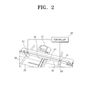
- a multifunction peripheral includes a main body 10, a printing unit 20, a driving unit 30, a scanning unit 40, and a linking unit 50.
- the main body 10 includes a document table 11 formed of a transparent flat plate, on which a document M can be placed.
- the printing unit 20 and the scanning unit 40 can be installed in the main body 10.
- the printing unit 20 is movably installed in the main body 10 to print an image signal received from the outside onto a printing medium P.
- the printing unit 20 may be an array head (not illustrated) having a plurality of nozzles arranged crosswise on the printing medium P to spit or eject ink onto the printing medium P to print an image.
- the printing unit 20 need not be an array head, and any of various printing methods can be employed.
- Ink is supplied to the printing unit 20 by an ink supplier 22, which consists of an ink reservoir 22a containing ink, and a supply hose 22b to supply ink from the ink reservoir 22a to the printing unit 20.
- the printing unit 20 may receive ink from the ink reservoir 22a, which is provided separately from the main body 10.
- a detailed description of technical configurations of a conventional separation type ink supplier 22 has been omitted for conciseness and clarity.
- the ink supplier 22 need not be a separation type ink supplier, and the printing unit 20 and ink supplier 22 can be integrally formed. Additionally, a plurality of ink reservoirs 22a can be provided to perform multi-color printing, and a single ink reservoir 22a can be provided to perform single color printing.
- the printing unit 20 is installed facing a platen 21, on which the printing medium P can be placed flat, to print an image on the printing medium P while in a fixed position or while moving lengthwise along the printing medium P.
- a maintenance unit (not illustrated) may be installed in the platen 21 to perform capping and wiping of the nozzles of the printing unit 20.
- a transferring unit 60 transfers the printing medium P on which an image is printed by the printing unit 20.
- the transferring unit 60 may include a charging roller 61, a first absorption belt 62 and a second absorption belt 63.
- the charging roller 61 charges the printing medium P and receives a voltage from a voltage applier (not illustrated).
- the first absorption belt 62 and the second absorption belt 63 move in contact with the charging roller 61 to electrostatically grip and transfer the charged printing medium P.
- the first absorption belt 62 and the second absorption belt 63 may move according to the printing region of the printing medium P.
- the driving unit 30 drives the printing unit 20, and includes a driving motor 31, a driving belt 32 and a printing unit guide bar 33.
- the driving motor 31 provides a driving force to drive the printing unit 20.
- the driving belt 32 is moved by the driving force of the driving motor 31 to drive the printing unit 20 while supporting the printing unit 20.
- the printing unit guide bar 33 supports and guides the movement of the printing unit 20.
- a pair of printing guide bars 33 may be installed to guide the printing unit 20.
- an image region formed on the printing medium P may be divided into at least two regions, and the printing unit 20 as configured above may be driven by the driving unit 30 to move back and forth at least once in each region. Accordingly, the printing unit 20 may move back and forth over a single image multiple times to print multiple copies of the image onto the printing medium P.
- the printing unit 20 may be operated to move horizontally across the printing medium P. Accordingly, there may be provided a second driving motor (not illustrated) to drive the printing unit 20 to move horizontally across the printing medium P, and a separate driving member to move the printing unit 20 in a direction orthogonal to the direction in which the printing medium P moves using a driving force of the second driving motor.
- a second driving motor not illustrated
- a separate driving member to move the printing unit 20 in a direction orthogonal to the direction in which the printing medium P moves using a driving force of the second driving motor.
- the scanning unit 40 is movably installed in the main body 10 to scan an image of a document M placed on the document table 11.
- the scanning unit 40 may include a light sensor, such as a contact image sensor (CIS) or a charge coupled device (CCD), to detect light reflected from the document M by irradiating light to the document M.
- CIS contact image sensor
- CCD charge coupled device
- the scanning unit 40 and printing unit 20 are movably and laminatedly disposed in parallel with each other in the main body 10. Specifically, the scanning unit 40 is disposed on a lower part of the document table 11, and the printing unit 20 is disposed on a lower part of the scanning unit 40. Movement of the scanning unit 40 may be guided by a scanning unit guide bar 41 which is disposed parallel to the printing unit guide bar 33.
- the linking unit 50 links the scanning unit 40 to the printing unit 20 being moved by the driving unit 30.
- the linking unit 50 includes a linking member 51 and a controller 52, as illustrated in Figure 2.
- the linking member 51 is disposed on a lower surface of the scanning unit 40, to be selectively connected to an upper surface of the printing unit 20.
- a linking member 51 may include an electromagnet, which can be selectively connected to the printing unit 20 by a magnetic force generated from an external voltage.
- the printing unit 20, which is connected to the linking member 51 including an electromagnet may be made of metals.
- the controller 52 controls the voltage supplied to the linking member 51 in response to a scanning signal received from the outside, and also controls the connection between the printing unit 20 and the scanning unit 40.
- the scanning signal may be input through an input key mounted on the outside of the main body 10 or through an external input means, such as a computer, which may be connected to the multifunction peripheral.
- An exemplary embodiment of the present general inventive concept provides the linking unit 50 including the linking member 51 including an electromagnet and the controller 52 to control the connection between the printing and scanning units 20 and 40, but the configuration of the multifunction peripheral is not necessarily limited thereto. Specifically, in the same manner as a locking projection is formed on the lower surface of the scanning unit 40 and a locking groove is formed on the upper surface of the printing unit 20, it is necessary to adopt one of various connecting means to selectively connect the scanning unit 40 to the printing unit 20 in response to the scanning signal outside the multifunction peripheral.
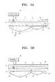
- the printing unit 20 moves in a direction indicated by an arrow A1 to be disposed on an upper part of the platen 21. If the printing medium is gripped by the first absorption belt 62 and the second absorption belt 63 with the electrostatic force generated between the charged printing medium P (charged by the charging roller 61) and the absorption belt, and is transferred toward the platen 21, the printing unit 20 spits ink to print a predetermined image onto the printing medium P.
- movements of the first absorption belt 62 and the second absorption belt 63 are paused to stop the transfer of the printing medium P. Thereafter, the printing unit 20 is operated to move back and forth lengthwise along the printing medium P to print multiple copies of the image.
- the printing unit 20 may move in a direction indicated by an arrow A2 to be displaced at a lower part of the scanning unit 40, as illustrated in Figure 3B.
- the controller 52 enables a predetermined voltage to be applied to the linking member 51, and the linking member 51 exerts a magnetic force. Accordingly, the lower surface of the scanning unit 40 and the upper surface of the printing unit 20 become interconnected.
- the scanning unit 40 connected to the printing unit 20 scans the image of the document M while being moved along the scanning unit guide bar 41 using a driving force of the driving motor 31 and the movement of the driving belt 32.
- the present general inventive concept provides a printing unit and a scanning unit which are selectively linked so that the printing unit and scanning unit may be driven by a single driving means. Accordingly, a multifunction peripheral has a simple structure, and thus, it is possible to make full use of space and reduce manufacturing costs.
Landscapes
- Engineering & Computer Science (AREA)
- Multimedia (AREA)
- Signal Processing (AREA)
- Facsimiles In General (AREA)
- Handling Of Sheets (AREA)
- Electrophotography Configuration And Component (AREA)
- Accessory Devices And Overall Control Thereof (AREA)
Applications Claiming Priority (1)
| Application Number | Priority Date | Filing Date | Title |
|---|---|---|---|
| KR1020060096369A KR20080029584A (ko) | 2006-09-29 | 2006-09-29 | 복합기 |
Publications (2)
| Publication Number | Publication Date |
|---|---|
| EP1909478A2 true EP1909478A2 (de) | 2008-04-09 |
| EP1909478A3 EP1909478A3 (de) | 2008-10-08 |
Family
ID=38846851
Family Applications (1)
| Application Number | Title | Priority Date | Filing Date |
|---|---|---|---|
| EP07110945A Withdrawn EP1909478A3 (de) | 2006-09-29 | 2007-06-25 | Multifunktionelles Peripheriegerät |
Country Status (4)
| Country | Link |
|---|---|
| US (1) | US20080079957A1 (de) |
| EP (1) | EP1909478A3 (de) |
| KR (1) | KR20080029584A (de) |
| CN (1) | CN101155235A (de) |
Families Citing this family (3)
| Publication number | Priority date | Publication date | Assignee | Title |
|---|---|---|---|---|
| KR101429526B1 (ko) * | 2007-10-18 | 2014-08-14 | 삼성전자주식회사 | 화상형성장치 및 그의 문서 관리 방법 |
| ITTO20110261A1 (it) * | 2011-03-25 | 2012-09-26 | St Microelectronics Srl | "apparecchio scanner, procedimento e prodotto informatico relativi" |
| CN110558736B (zh) * | 2019-09-02 | 2022-07-15 | 邹瑜 | 一种多功能书桌 |
Family Cites Families (4)
| Publication number | Priority date | Publication date | Assignee | Title |
|---|---|---|---|---|
| JPH0750732A (ja) * | 1993-08-04 | 1995-02-21 | Nippon Conlux Co Ltd | 携帯用複写機 |
| KR100234432B1 (ko) * | 1997-05-08 | 1999-12-15 | 윤종용 | 셔틀 방식 스캔 장치의 프리 스캔 방법 |
| US20060132520A1 (en) * | 2004-12-16 | 2006-06-22 | Bledsoe James D | Multiple-function inkjet printing system with single motor for carriage and scan head motion |
| EP1681845A3 (de) * | 2005-01-18 | 2006-10-18 | Samsung Electronics Co., Ltd. | Drucken und Abtasten von Information |
-
2006
- 2006-09-29 KR KR1020060096369A patent/KR20080029584A/ko not_active Withdrawn
-
2007
- 2007-04-04 US US11/696,319 patent/US20080079957A1/en not_active Abandoned
- 2007-05-24 CN CNA200710104892XA patent/CN101155235A/zh active Pending
- 2007-06-25 EP EP07110945A patent/EP1909478A3/de not_active Withdrawn
Also Published As
| Publication number | Publication date |
|---|---|
| KR20080029584A (ko) | 2008-04-03 |
| US20080079957A1 (en) | 2008-04-03 |
| EP1909478A3 (de) | 2008-10-08 |
| CN101155235A (zh) | 2008-04-02 |
Similar Documents
| Publication | Publication Date | Title |
|---|---|---|
| US8226206B2 (en) | Image recording apparatus | |
| US8414105B2 (en) | Image forming apparatus | |
| US7712892B2 (en) | Image forming apparatus | |
| US7445330B2 (en) | Image forming apparatus | |
| US8770739B2 (en) | Image forming apparatus | |
| US7850277B2 (en) | Integrated maintenance and paper pick system | |
| US7418235B2 (en) | Method and apparatus for image forming | |
| US7578572B2 (en) | Image forming apparatus using inkjet process capable of maintaining an image forming quality | |
| US7510263B2 (en) | Image forming apparatus | |
| EP1909478A2 (de) | Multifunktionelles Peripheriegerät | |
| CN100443306C (zh) | 成像装置 | |
| US8613441B2 (en) | Sheet transport device and image forming apparatus | |
| US20080012921A1 (en) | Image forming apparatus | |
| JP4460374B2 (ja) | 静電搬送装置及び画像形成装置 | |
| EP1764229B1 (de) | Bilderzeugungsvorrichtung | |
| JP4533012B2 (ja) | 画像形成装置 | |
| JP4553666B2 (ja) | 画像形成装置 | |
| US7896464B2 (en) | Printhead restraint system | |
| GB2394445A (en) | Inkjet printhead servicing station wherein one of the servicing modules is detachably connected to another servicing module(s) via a rotatable hook | |
| JP4340223B2 (ja) | 静電吸着装置、これを用いた画像形成装置 | |
| JPH07178978A (ja) | 記録装置 | |
| JP2013111877A (ja) | 画像形成装置 | |
| JP2006150599A (ja) | 画像形成装置 | |
| JPH08127163A (ja) | 記録読取装置 | |
| JP2006076197A (ja) | 画像形成装置 |
Legal Events
| Date | Code | Title | Description |
|---|---|---|---|
| PUAI | Public reference made under article 153(3) epc to a published international application that has entered the european phase |
Free format text: ORIGINAL CODE: 0009012 |
|
| AK | Designated contracting states |
Kind code of ref document: A2 Designated state(s): AT BE BG CH CY CZ DE DK EE ES FI FR GB GR HU IE IS IT LI LT LU LV MC MT NL PL PT RO SE SI SK TR |
|
| AX | Request for extension of the european patent |
Extension state: AL BA HR MK RS |
|
| PUAL | Search report despatched |
Free format text: ORIGINAL CODE: 0009013 |
|
| AK | Designated contracting states |
Kind code of ref document: A3 Designated state(s): AT BE BG CH CY CZ DE DK EE ES FI FR GB GR HU IE IS IT LI LT LU LV MC MT NL PL PT RO SE SI SK TR |
|
| AX | Request for extension of the european patent |
Extension state: AL BA HR MK RS |
|
| AKX | Designation fees paid | ||
| REG | Reference to a national code |
Ref country code: DE Ref legal event code: 8566 |
|
| STAA | Information on the status of an ep patent application or granted ep patent |
Free format text: STATUS: THE APPLICATION IS DEEMED TO BE WITHDRAWN |
|
| 18D | Application deemed to be withdrawn |
Effective date: 20090409 |