EP1909338A2 - Anordnung eines Piezoaktors mit einer Isolationsschicht - Google Patents
Anordnung eines Piezoaktors mit einer Isolationsschicht Download PDFInfo
- Publication number
- EP1909338A2 EP1909338A2 EP07115384A EP07115384A EP1909338A2 EP 1909338 A2 EP1909338 A2 EP 1909338A2 EP 07115384 A EP07115384 A EP 07115384A EP 07115384 A EP07115384 A EP 07115384A EP 1909338 A2 EP1909338 A2 EP 1909338A2
- Authority
- EP
- European Patent Office
- Prior art keywords
- metal foil
- layer
- actuator
- arrangement according
- piezoelectric
- Prior art date
- Legal status (The legal status is an assumption and is not a legal conclusion. Google has not performed a legal analysis and makes no representation as to the accuracy of the status listed.)
- Granted
Links
- 239000011888 foil Substances 0.000 claims abstract description 23
- 239000002184 metal Substances 0.000 claims abstract description 23
- 238000009413 insulation Methods 0.000 claims abstract description 4
- 239000000446 fuel Substances 0.000 claims description 10
- 238000002485 combustion reaction Methods 0.000 claims description 7
- 238000002347 injection Methods 0.000 claims description 5
- 239000007924 injection Substances 0.000 claims description 5
- 229910001374 Invar Inorganic materials 0.000 claims description 3
- 238000007789 sealing Methods 0.000 claims description 3
- 239000010410 layer Substances 0.000 description 15
- 239000000463 material Substances 0.000 description 3
- 239000013078 crystal Substances 0.000 description 2
- 238000004519 manufacturing process Methods 0.000 description 2
- 229910000831 Steel Inorganic materials 0.000 description 1
- 239000000919 ceramic Substances 0.000 description 1
- 238000006243 chemical reaction Methods 0.000 description 1
- 238000010276 construction Methods 0.000 description 1
- 230000006735 deficit Effects 0.000 description 1
- 230000000694 effects Effects 0.000 description 1
- 230000009931 harmful effect Effects 0.000 description 1
- 238000009434 installation Methods 0.000 description 1
- 239000011810 insulating material Substances 0.000 description 1
- 238000002955 isolation Methods 0.000 description 1
- 239000007788 liquid Substances 0.000 description 1
- 230000036316 preload Effects 0.000 description 1
- 239000002356 single layer Substances 0.000 description 1
- 239000010959 steel Substances 0.000 description 1
Images
Classifications
-
- H—ELECTRICITY
- H10—SEMICONDUCTOR DEVICES; ELECTRIC SOLID-STATE DEVICES NOT OTHERWISE PROVIDED FOR
- H10N—ELECTRIC SOLID-STATE DEVICES NOT OTHERWISE PROVIDED FOR
- H10N30/00—Piezoelectric or electrostrictive devices
- H10N30/80—Constructional details
- H10N30/88—Mounts; Supports; Enclosures; Casings
- H10N30/883—Additional insulation means preventing electrical, physical or chemical damage, e.g. protective coatings
-
- F—MECHANICAL ENGINEERING; LIGHTING; HEATING; WEAPONS; BLASTING
- F02—COMBUSTION ENGINES; HOT-GAS OR COMBUSTION-PRODUCT ENGINE PLANTS
- F02M—SUPPLYING COMBUSTION ENGINES IN GENERAL WITH COMBUSTIBLE MIXTURES OR CONSTITUENTS THEREOF
- F02M51/00—Fuel-injection apparatus characterised by being operated electrically
- F02M51/06—Injectors peculiar thereto with means directly operating the valve needle
- F02M51/0603—Injectors peculiar thereto with means directly operating the valve needle using piezoelectric or magnetostrictive operating means
-
- H—ELECTRICITY
- H10—SEMICONDUCTOR DEVICES; ELECTRIC SOLID-STATE DEVICES NOT OTHERWISE PROVIDED FOR
- H10N—ELECTRIC SOLID-STATE DEVICES NOT OTHERWISE PROVIDED FOR
- H10N30/00—Piezoelectric or electrostrictive devices
- H10N30/50—Piezoelectric or electrostrictive devices having a stacked or multilayer structure
Definitions
- the invention relates to an arrangement with an insulated piezoelectric actuator, for example, in a piezoelectric actuator flowed around by liquid media, which can be used in a piezo injector for time and volume precise metering of fuel in an internal combustion engine, according to the generic features of the main claim.
- Such a piezoelectric injector essentially consists of a holding body and the piezoelectric actuator arranged in the holding body, which has piezolayers arranged one above the other and arranged between an actuator head and an actuator foot, stacked one above the other.
- the piezoelectric elements can be used so that by utilizing the so-called piezoelectric effect, a control of the needle stroke of a valve or the like can be made.
- the piezoelectric layers of the piezoelectric elements are constructed of a material having a suitable crystal structure such that upon application of an external electrical voltage, a mechanical reaction of the piezoelectric elements takes place, which represents a pressure or tension in a predeterminable direction as a function of the crystal structure and the contact regions of the electrical voltage ,
- Such piezoelectric actuators are suitable, for example, for applications in which lifting movements take place under high operating forces and high clock frequencies.
- piezoelectric actuator as part of a piezoelectric injector in so-called common rail injection systems (CR injector) from the DE 10026005 A1 known.
- a stack of a plurality of electrically and mechanically coupled together piezo elements is also present, via a Actuator base and an actuator head are held under preload between two stops.
- Each piezoceramic layer is enclosed as a piezoelectric layer for forming the piezoelectric elements between two internal electrodes, via which an electrical voltage can be applied from the outside. Because of this electrical voltage, the piezoelectric elements then each carry out small strokes in the direction of the potential gradient, which add up to the total stroke of the piezoelectric actuator. This total stroke is variable by the amount of voltage applied and can be transferred to a mechanical actuator.
- the invention is based on an arrangement described above with a piezoelectric actuator which has piezo elements clamped between an actuator head and an actuator foot and is provided with an insulating layer of plastic surrounding at least the piezoelements.
- the insulating layer and at least adjacent edge regions of the actuator head and the actuator base are provided according to the invention in an advantageous manner with at least one layer of a sealing metal foil.
- the inventively applied at least one layer of the metal foil has a relatively low coefficient of thermal expansion, so that the metal foil in addition to the stroke of the piezoelectric actuator does not have to compensate for the thermal expansion of the piezoelectric actuator, which may well be in the order of its stroke.
- the temperature range to be considered for the thermal expansion can be between -45 ° C and + 140 ° C.
- the thermal expansion coefficient of the piezoelectric actuator is about -6 * 10 -6 1 / K. So that the metal foil is not stretched too much by the thermal expansion of the piezoelectric actuator, the metal foil should be made of a material whose coefficient of thermal expansion is close to that of ceramic (about -6 to + 6 * 10 -6 1 / K). Such a material is Invar, for example.
- the at least one layer of the metal foil may have, for example, a layer thickness of 2 to 10 m.
- multilayer metal foil arrangements for example up to five or more layers, are advantageous in the invention, with which a number of functions such as tightness, isolation or flexibility can be improved, but also single-layer arrangements, especially because of the ease of installation, makes sense could be.
- the layers of the metal foil can be applied flat or wound over in an overlapping manner.
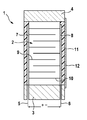
- an arrangement 1 with a piezoelectric actuator 2 with, for example, angular or circular geometry is shown in longitudinal section, which can be used for example for Nadelhub Kunststoffung in an injection system for fuel for an internal combustion engine.
- the piezoelectric actuator 2 also has an actuator base 3 and an actuator head 4, for example made of steel.
- the inner electrodes 9 and 10 each form a piezoelectric element with an interposed piezoelectric layer, so that the stack of the superimposed piezoelectric elements forms the acting piezoelectric actuator 2.
- a mechanical arrangement located on the actuator head 4 can be actuated by the caused stroke.
- the arrangement with the piezoelectric actuator 2 is installed in an injector body, not shown here, wherein the fuel is guided past the arrangement 1 through the interior of the injector body.
- This fuel can then be injected for example in a so-called common rail system (CR system) under the rail pressure mentioned in the introduction or another predetermined pressure of the fuel in the combustion chamber of an internal combustion engine, not shown here.
- CR system common rail system
- a particularly flexible insulating layer 11 made of plastic is present, which in turn is provided with a metal foil 12.
- the inventively applied at least one layer of metal foil 12, for example from Invar, has a relatively low coefficient of thermal expansion, so that thermal expansion can be compensated, which may be in the order of magnitude of the stroke of the piezoelectric actuator 2. This is especially important when the piezoelectric actuator 2 is part of a piezo injector for an injection system for fuel in an internal combustion engine and the temperature range to be considered between -45 C ° and +140 C ° may be.
- the metal foil 12 extends at least into the adjacent edge regions of the actuator head 4 and / or the actuator base 3, so that the at least one layer of the metal foil 12 can also be applied to the piezoelectric elements or the piezoactuator 2 in a sealing manner.
Landscapes
- Fuel-Injection Apparatus (AREA)
- Insulated Metal Substrates For Printed Circuits (AREA)
Abstract
Description
- Die Erfindung betrifft eine Anordnung mit einem isolierten Piezoaktor, beispielsweise bei einem von flüssigen Medien umströmten Piezoaktor, der in einem Piezoinjektor zur zeitpunkt- und mengengenauen Dosierung von Kraftstoff in einem Verbrennungsmotor einsetzbar ist, nach den gattungsgemäßen Merkmalen des Hauptanspruchs.
- Ein solcher Piezoinjektor besteht im Wesentlichen aus einem Haltekörper und dem in dem Haltekörper angeordneten Piezoaktor, der zwischen einem Aktorkopf und einem Aktorfuß angeordnete, übereinandergestapelte Piezoelemente mit Piezolagen aufweist.
- Es ist an sich bekannt, dass zum Aufbau des zuvor erwähnten Piezoaktors die Piezoelemente so eingesetzt werden können, dass unter Ausnutzung des sogenannten Piezoeffekts eine Steuerung des Nadelhubes eines Ventils oder dergleichen vorgenommen werden kann. Die Piezolagen der Piezoelemente sind aus einem Material mit einer geeigneten Kristallstruktur so aufgebaut, dass bei Anlage einer äußeren elektrischen Spannung eine mechanische Reaktion der Piezoelemente erfolgt, die in Abhängigkeit von der Kristallstruktur und der Anlagebereiche der elektrischen Spannung einen Druck oder Zug in eine vorgebbare Richtung darstellt. Derartige Piezoaktoren eignen sich beispielsweise für Anwendungen, bei denen Hubbewegungen unter hohen Betätigungskräften und hohen Taktfrequenzen ablaufen.
- Beispielsweise ist ein solcher Piezoaktor als Bestandteil eines Piezoinjektors in sogenannten Common Rail Einspritzsystemen (CR-Injektor) aus der
DE 10026005 A1 bekannt. Bei diesem Piezoaktor ist ebenfalls ein Stapel mehrerer elektrisch und mechanisch miteinander gekoppelter Piezoelemente vorhanden, die über einen Aktorfuß und einen Aktorkopf unter Vorspannung zwischen zwei Anschlägen gehalten sind. Jede piezokeramische Schicht ist als Piezolage zur Bildung der Piezoelemente zwischen zwei Innenelektroden eingefasst, über die von außen eine elektrische Spannung angelegt werden kann. Aufgrund dieser elektrischen Spannung führen die Piezoelemente dann jeweils kleine Hubbewegungen in Richtung des Potenzialgefälles aus, die sich zum Gesamthub des Piezoaktors addieren. Dieser Gesamthub ist über die Höhe der angelegten Spannung veränderbar und kann auf ein mechanisches Stellglied übertragen werden. - Um eine elektrische und mechanische Isolierung des Piezoaktors zu erreichen, wird oft auch eine flexible Ummantelung des Piezoaktors vorgeschlagen. Aus der
DE 10230032 A1 ist zur Vermeidung von Beeinträchtigungen der Piezoelemente eine Anordnung mit einem Piezoaktor in umströmenden Medien bekannt, bei der die Piezoelemente in einer formveränderlichen Isolationsmasse vergossen sind, die wiederum in einem seitlich und am oberen und unteren Ende gegenüber dem Medium verschlossenen Gehäusemantel eingebracht ist, was einen großen Herstellungsaufwand erforderlich macht. - Die Erfindung geht von einer eingangs beschriebenen Anordnung mit einem Piezoaktor aus, der zwischen einem Aktorkopf und einem Aktorfuß eingespannte Piezoelemente aufweist und mit einer zumindest die Piezoelemente umgebenden Isolationsschicht aus Kunststoff versehen ist. Die Isolationsschicht und zumindest angrenzende Randbereiche des Aktorkopfs und des Aktorfußes sind erfindungsgemäß in vorteilhafter Weise mit mindestens einer Lage einer abdichtenden Metallfolie versehen.
- Die erfindungsgemäß aufgetragene mindestens eine Lage der Metallfolie weist einen relativ geringen Wärmeausdehnungskoeffizienten auf, damit die Metallfolie zusätzlich zum Hub des Piezoaktors nicht auch noch die Wärmedehnung des Piezoaktors ausgleichen muss, die durchaus auch in der Größenordnung seines Hubes liegen kann.
- Insbesondere wenn der mit der erfindungsgemäßen Anordnung gebildete Piezoaktor Bestandteil eines Piezoinjektors für ein Einspritzsystem für Kraftstoff bei einem Verbrennungsmotor ist, kann der zu berücksichtigende Temperaturbereich für die Wärmedehnung zwischen -45C° und +140C° liegen.
- Der Wärmeausdehnungskoeffizient des Piezoaktors beträgt ca. -6* 10-6 1/K. Damit die Metallfolie durch die Wärmedehnung des Piezoaktors nicht zu stark gedehnt wird, sollte die Metallfolie aus einem Material sein, dessen Wärmeausdehnungskoeffizient nahe dem von Keramik liegt (ca. -6 bis +6* 10-6 1/K). Ein solches Material ist zum Beispiel Invar. Die mindestens eine Lage der Metallfolie kann dabei beispielsweise eine Schichtdicke von 2 bis 10 m aufweisen.
- Insbesondere sind bei der Erfindung auch mehrlagige Metallfolienanordnungen, zum Beispiel bis zu fünf oder mehr Lagen, vorteilhaft, mit denen eine Reihe von Funktionen, wie Dichtheit, Isolation oder Flexibilität verbessert werden können, wobei jedoch auch einlagige Anordnungen, besonders wegen der einfachen Anbringung, sinnvoll sein können.
- Während der Herstellung des Piezoaktors können die Lagen der Metallfolie flächig aufgetragen oder auch überlappend aufgewickelt werden.
- Ein Ausführungsbeispiel einer erfindungsgemäßen Anordnung mit einem Piezoaktor wird anhand der Zeichnung erläutert. Es zeigt:
- Eine einzige Figur einen Längsschnitt durch eine Anordnung mit einem Piezoaktor mit einer Metallfolie, der Bestandteil eines hier nicht dargestellten Piezoinjektors sein kann.
- In der Figur ist ein eine Anordnung 1 mit einem Piezoaktor 2 mit beispielsweise eckiger oder runder Geometrie im Längsschnitt gezeigt, der zum Beispiel zur Nadelhubsteuerung in einem Einspritzsystem für Kraftstoff für einen Verbrennungsmotor eingesetzt werden kann. Der Piezoaktor 2 weist weiterhin noch einen Aktorfuß 3 und einen Aktorkopf 4, zum Beispiel aus Stahl, auf. Es sind elektrische Zuleitungen 6 und 7 durch den Aktorfuß 3 geführt, die über Außenelektroden 7 und 8 an Innenelektroden 9 und 10 kontaktiert sind.
- Die Innenelektroden 9 und 10 bilden jeweils mit einer dazwischenliegenden Piezolage ein Piezoelement, sodass der Stapel aus den übereinanderliegenden Piezoelementen den agierenden Piezoaktor 2 bildet. Bei einer Betätigung des Piezoaktors 2 durch eine Spannungsbeaufschlagung der Innenelektroden 9 und 10 über die Zuleitungen 5 und 6 sowie über die Außenelektroden 7 und 8 kann eine am Aktorkopf 4 befindliche mechanische Anordnung durch den verursachten Hub betätigt werden.
- Die Anordnung mit dem Piezoaktor 2 ist in einen hier nicht gezeigten Injektorkörper eingebaut, wobei der Kraftstoff durch den Innenraum des Injektorkörpers an der Anordnung 1 vorbeigeführt wird. Dieser Kraftstoff kann dann beispielsweise bei einem sogenannten Common Rail System (CR-System) unter dem in der Beschreibungseinleitung erwähnten Raildruck oder einem anderen vorgebbaren Druck des Kraftstoffs in den Brennraum eines hier nicht dargestellten Verbrennungsmotors injiziert werden.
- Um den Piezoaktor 2 nach der Figur vor dem umströmenden Kraftstoff und vor sonstigen schädlichen Einwirkungen zu schützen, ist eine insbesondere flexible Isolationsschicht 11 aus Kunststoff vorhanden, die wiederum mit einer Metallfolie 12 versehen ist.
- Die erfindungsgemäß aufgetragene mindestens eine Lage der Metallfolie 12, zum Beispiel aus Invar, weist einen relativ geringen Wärmeausdehnungskoeffizienten auf, damit Wärmedehnungen ausgeglichen werden können, die eventuell in der Größenordnung des Hubes des Piezoaktors 2 liegen. Dies ist vor allem dann von Bedeutung, wenn der Piezoaktor 2 Bestandteil eines Piezoinjektors für ein Einspritzsystem für Kraftstoff bei einem Verbrennungsmotor ist und der zu berücksichtigende Temperaturbereich zwischen -45 C° und +140 C° liegen kann.
- Die Metallfolie 12 reicht dabei zumindest bis in die angrenzenden Randbereiche des Aktorkopfs 4 und/oder des Aktorfußes 3, damit die mindestens eine Lage der Metallfolie 12 auch dichtend auf die Piezoelemente bzw. den Piezoaktor 2 aufgetragen werden kann.
Claims (9)
- Anordnung mit einem Piezoaktor (2) mit zwischen einem Aktorkopf (4) und einem Aktorfuß (3) eingespannten Piezoelementen und mit einer zumindest die Piezoelemente umgebenden Isolationsschicht (11) aus Kunststoff, dadurch gekennzeichnet, dass auf die Isolationsschicht (11) und zumindest bis in die angrenzenden Randbereiche des Aktorkopfs (3) und/oder des Aktorfußes (3) mindestens eine Lage einer Metallfolie (12) abdichtend aufgetragen ist.
- Anordnung nach Anspruch 1, dadurch gekennzeichnet, dass die mindestens eine Lage der Metallfolie (12) einen geringen Wärmeausdehnungskoeffizienten aufweist.
- Anordnung nach Anspruch 2, dadurch gekennzeichnet, der Wärmeausdehnungskoeffizienten einen Betrag von ca. 0 bis 6* 10-6 1/K aufweist.
- Anordnung nach Anspruch 1, 2 oder 3, dadurch gekennzeichnet, dass die mindestens eine Lage der Metallfolie (12) eine Schichtdicke von 2 bis 10 µm aufweist.
- Anordnung nach einem der vorhergehenden Ansprüche, dadurch gekennzeichnet, dass die mindestens eine Lage der Metallfolie (12) aus Invar ist.
- Anordnung nach einem der vorhergehenden Ansprüche, dadurch gekennzeichnet, dass zwei bis fünf Lagen der Metallfolie (12) aufgetragen sind.
- Anordnung nach einem der vorhergehenden Ansprüche, dadurch gekennzeichnet, dass die mindestens eine Lage der Metallfolie (12) flächig aufgetragen ist.
- Anordnung nach einem der Ansprüche 1 bis 6, dadurch gekennzeichnet, dass die mindestens eine Lage der Metallfolie (12) überlappend aufgewickelt ist.
- Anordnung nach einem der vorhergehenden Ansprüche, dadurch gekennzeichnet, dass der in der Anordnung gebildete Piezoaktor (2) Bestandteil eines Piezoinjektors für ein Einspritzsystem für Kraftstoff bei einem Verbrennungsmotor ist, wobei der Kraftstoff die Metallfolie (12) des Piezoaktors (2) umströmt.
Applications Claiming Priority (1)
| Application Number | Priority Date | Filing Date | Title |
|---|---|---|---|
| DE102006046831A DE102006046831A1 (de) | 2006-10-02 | 2006-10-02 | Anordnung eines Piezoaktors mit einer Isolationsschicht |
Publications (3)
| Publication Number | Publication Date |
|---|---|
| EP1909338A2 true EP1909338A2 (de) | 2008-04-09 |
| EP1909338A3 EP1909338A3 (de) | 2011-08-17 |
| EP1909338B1 EP1909338B1 (de) | 2013-07-24 |
Family
ID=38894004
Family Applications (1)
| Application Number | Title | Priority Date | Filing Date |
|---|---|---|---|
| EP07115384.5A Ceased EP1909338B1 (de) | 2006-10-02 | 2007-08-31 | Anordnung eines Piezoaktors mit einer Isolationsschicht |
Country Status (2)
| Country | Link |
|---|---|
| EP (1) | EP1909338B1 (de) |
| DE (1) | DE102006046831A1 (de) |
Families Citing this family (1)
| Publication number | Priority date | Publication date | Assignee | Title |
|---|---|---|---|---|
| DE102008048051B4 (de) | 2008-09-19 | 2018-04-05 | Continental Automotive Gmbh | Bauelement sowie Verfahren zum Kontaktieren eines Bauelements |
Family Cites Families (2)
| Publication number | Priority date | Publication date | Assignee | Title |
|---|---|---|---|---|
| JPH0294680A (ja) * | 1988-09-30 | 1990-04-05 | Nec Corp | 電歪効果素子の製造方法 |
| DE102006022997A1 (de) * | 2006-05-17 | 2007-11-22 | Robert Bosch Gmbh | Piezoaktor |
-
2006
- 2006-10-02 DE DE102006046831A patent/DE102006046831A1/de not_active Withdrawn
-
2007
- 2007-08-31 EP EP07115384.5A patent/EP1909338B1/de not_active Ceased
Non-Patent Citations (1)
| Title |
|---|
| None |
Also Published As
| Publication number | Publication date |
|---|---|
| EP1909338A3 (de) | 2011-08-17 |
| EP1909338B1 (de) | 2013-07-24 |
| DE102006046831A1 (de) | 2008-04-03 |
Similar Documents
| Publication | Publication Date | Title |
|---|---|---|
| EP2030262B1 (de) | Anordnung mit einem beschichteten piezoaktor | |
| WO2007131965A1 (de) | Piezoaktor | |
| EP1909338B1 (de) | Anordnung eines Piezoaktors mit einer Isolationsschicht | |
| EP2030263A2 (de) | Piezoelektrischer aktor | |
| EP2058873B1 (de) | Piezoaktor und Piezoaktormodul mit einem Schutzschichtsystem | |
| WO2007131964A1 (de) | Anordnung mit einem von flüssigen medien umströmten piezoaktor | |
| EP2031669B1 (de) | Piezoaktormodul mit einer Umhüllung des Piezoaktors und ein Verfahren zu dessen Herstellung | |
| EP1503435B1 (de) | Verfahren zur Herstellung eines Piezoaktors | |
| EP1919004B1 (de) | Piezoaktormodul oder Piezoaktor mit einem ummantelnden Schutzschichtsystem | |
| WO2010108710A1 (de) | Piezoaktor mit einem mehrlagenaufbau und ein verfahren zu dessen herstellung | |
| EP1981097B1 (de) | Verfahren zur Herstellung eines piezoelektrischen Aktors | |
| EP2013923B1 (de) | Piezoaktor mit einer ummantelung | |
| DE102006043709A1 (de) | Anordnung eines Piezoaktors in einem Gehäuse | |
| EP1919005A2 (de) | Anordnung eines Piezoaktors in einer Hülse eines Piezoaktormoduls | |
| EP2013922A1 (de) | Piezoaktormodul mit einer ummantelung und ein verfahren zu dessen herstellung | |
| EP2071645B1 (de) | Piezoaktor mit einem Multilagenaufbau von Piezoelementen | |
| DE102007040510A1 (de) | Aktorkopf für ein Piezoaktormodul und Piezoaktormodul | |
| EP2149921B1 (de) | Piezoaktor mit passiven Bereichen am Kopf und/oder am Fuss | |
| DE102007042402A1 (de) | Piezoaktormodul mit einem Schutzschichtsystem und ein Verfahren zu dessen Herstellung | |
| EP1909339A1 (de) | Aktormodul mit einem umhüllten Piezoaktor | |
| DE102008042110A1 (de) | Piezoaktor mit einem Mehrlagenaufbau und ein Verfahren zu dessen Herstellung | |
| DE102007056553A1 (de) | Verfahren zur Herstellung eines Piezoaktormoduls mit einer Umhüllung und ein so hergestelltes Piezoaktormodul | |
| DE102009002837A1 (de) | Piezoaktor mit innenliegender Kontaktierung | |
| DE102007001566A1 (de) | Verfahren zur Isolierung des aktiven Bereichs eines Piezoaktors und Piezoaktor | |
| EP2109160A1 (de) | Piezoaktormodul für eine von einem Medium umströmte Anordnung |
Legal Events
| Date | Code | Title | Description |
|---|---|---|---|
| PUAI | Public reference made under article 153(3) epc to a published international application that has entered the european phase |
Free format text: ORIGINAL CODE: 0009012 |
|
| AK | Designated contracting states |
Kind code of ref document: A2 Designated state(s): AT BE BG CH CY CZ DE DK EE ES FI FR GB GR HU IE IS IT LI LT LU LV MC MT NL PL PT RO SE SI SK TR |
|
| AX | Request for extension of the european patent |
Extension state: AL BA HR MK RS |
|
| PUAL | Search report despatched |
Free format text: ORIGINAL CODE: 0009013 |
|
| AK | Designated contracting states |
Kind code of ref document: A3 Designated state(s): AT BE BG CH CY CZ DE DK EE ES FI FR GB GR HU IE IS IT LI LT LU LV MC MT NL PL PT RO SE SI SK TR |
|
| AX | Request for extension of the european patent |
Extension state: AL BA HR MK RS |
|
| RIC1 | Information provided on ipc code assigned before grant |
Ipc: F02M 51/06 20060101ALI20110711BHEP Ipc: H01L 41/053 20060101AFI20110711BHEP |
|
| 17P | Request for examination filed |
Effective date: 20120217 |
|
| AKX | Designation fees paid |
Designated state(s): DE ES FR |
|
| GRAP | Despatch of communication of intention to grant a patent |
Free format text: ORIGINAL CODE: EPIDOSNIGR1 |
|
| INTG | Intention to grant announced |
Effective date: 20130412 |
|
| GRAS | Grant fee paid |
Free format text: ORIGINAL CODE: EPIDOSNIGR3 |
|
| GRAA | (expected) grant |
Free format text: ORIGINAL CODE: 0009210 |
|
| AK | Designated contracting states |
Kind code of ref document: B1 Designated state(s): DE ES FR |
|
| REG | Reference to a national code |
Ref country code: DE Ref legal event code: R096 Ref document number: 502007012070 Country of ref document: DE Effective date: 20130919 |
|
| PG25 | Lapsed in a contracting state [announced via postgrant information from national office to epo] |
Ref country code: ES Free format text: LAPSE BECAUSE OF FAILURE TO SUBMIT A TRANSLATION OF THE DESCRIPTION OR TO PAY THE FEE WITHIN THE PRESCRIBED TIME-LIMIT Effective date: 20130724 |
|
| PLBE | No opposition filed within time limit |
Free format text: ORIGINAL CODE: 0009261 |
|
| STAA | Information on the status of an ep patent application or granted ep patent |
Free format text: STATUS: NO OPPOSITION FILED WITHIN TIME LIMIT |
|
| 26N | No opposition filed |
Effective date: 20140425 |
|
| REG | Reference to a national code |
Ref country code: DE Ref legal event code: R097 Ref document number: 502007012070 Country of ref document: DE Effective date: 20140425 |
|
| REG | Reference to a national code |
Ref country code: FR Ref legal event code: PLFP Year of fee payment: 10 |
|
| REG | Reference to a national code |
Ref country code: FR Ref legal event code: PLFP Year of fee payment: 11 |
|
| REG | Reference to a national code |
Ref country code: FR Ref legal event code: PLFP Year of fee payment: 12 |
|
| PGFP | Annual fee paid to national office [announced via postgrant information from national office to epo] |
Ref country code: FR Payment date: 20190822 Year of fee payment: 13 |
|
| PGFP | Annual fee paid to national office [announced via postgrant information from national office to epo] |
Ref country code: DE Payment date: 20191021 Year of fee payment: 13 |
|
| REG | Reference to a national code |
Ref country code: DE Ref legal event code: R119 Ref document number: 502007012070 Country of ref document: DE |
|
| PG25 | Lapsed in a contracting state [announced via postgrant information from national office to epo] |
Ref country code: DE Free format text: LAPSE BECAUSE OF NON-PAYMENT OF DUE FEES Effective date: 20210302 Ref country code: FR Free format text: LAPSE BECAUSE OF NON-PAYMENT OF DUE FEES Effective date: 20200831 |