EP1909285A2 - Verfahren und System zur Messung der Reaktion eines CD-Players auf Vibrationen während des Abspielens einer CD - Google Patents
Verfahren und System zur Messung der Reaktion eines CD-Players auf Vibrationen während des Abspielens einer CD Download PDFInfo
- Publication number
- EP1909285A2 EP1909285A2 EP07117406A EP07117406A EP1909285A2 EP 1909285 A2 EP1909285 A2 EP 1909285A2 EP 07117406 A EP07117406 A EP 07117406A EP 07117406 A EP07117406 A EP 07117406A EP 1909285 A2 EP1909285 A2 EP 1909285A2
- Authority
- EP
- European Patent Office
- Prior art keywords
- simulated
- processing circuitry
- digital
- circuitry
- audio
- Prior art date
- Legal status (The legal status is an assumption and is not a legal conclusion. Google has not performed a legal analysis and makes no representation as to the accuracy of the status listed.)
- Withdrawn
Links
Images


Classifications
-
- G—PHYSICS
- G11—INFORMATION STORAGE
- G11B—INFORMATION STORAGE BASED ON RELATIVE MOVEMENT BETWEEN RECORD CARRIER AND TRANSDUCER
- G11B27/00—Editing; Indexing; Addressing; Timing or synchronising; Monitoring; Measuring tape travel
- G11B27/36—Monitoring, i.e. supervising the progress of recording or reproducing
-
- G—PHYSICS
- G11—INFORMATION STORAGE
- G11B—INFORMATION STORAGE BASED ON RELATIVE MOVEMENT BETWEEN RECORD CARRIER AND TRANSDUCER
- G11B19/00—Driving, starting, stopping record carriers not specifically of filamentary or web form, or of supports therefor; Control thereof; Control of operating function ; Driving both disc and head
- G11B19/02—Control of operating function, e.g. switching from recording to reproducing
- G11B19/04—Arrangements for preventing, inhibiting, or warning against double recording on the same blank or against other recording or reproducing malfunctions
- G11B19/048—Testing of disk drives, e.g. to detect defects or prevent sudden failure
-
- G—PHYSICS
- G11—INFORMATION STORAGE
- G11B—INFORMATION STORAGE BASED ON RELATIVE MOVEMENT BETWEEN RECORD CARRIER AND TRANSDUCER
- G11B20/00—Signal processing not specific to the method of recording or reproducing; Circuits therefor
- G11B20/10—Digital recording or reproducing
- G11B20/18—Error detection or correction; Testing, e.g. of drop-outs
- G11B20/1816—Testing
Definitions
- the present invention is generally directed to optical digital disk player testing systems and methods, and, more specifically, to a system and method for testing the response of optical digital disk players to vibration encountered during playback of optical digital disks.
- Optical digital disk players such as, for example, audio compact disk (CD) players, are frequently employed in automobiles as a means for providing audio entertainment to vehicle occupants.
- CD players are typically designed to compensate for anomalies that can be encountered during the audio CD playback process that might otherwise act to interrupt and/or distort the audio produced during the CD playback process.
- anomalies that can be encountered during the CD playback process include defects on the CD itself, such as, for example, scratches, smudges, spots, manufacturing defects and/or dirt located on the surface of the CD.
- Other anomalies that can be encountered during the audio CD playback process include physical shocks and vibrations introduced into the CD player.
- Fig. 1 generally illustrates components typically included in a conventional CD player 20.
- CD player 20 includes a laser diode (not shown) for projecting a light beam on a surface of a CD 50 placed in the CD player 20.
- CD player 20 also includes a pickup mechanism 22 for reading signals from the CD 50 and providing them to additional circuitry in the CD player 20 for processing.
- pickup mechanism 22 includes a photosensor 11, sled adjustment mechanism 18, tracking adjustment mechanism 14 and focus adjustment mechanism 16.
- Sled adjustment mechanism 18, tracking adjustment mechanism 14, and focus adjustment mechanism 16 are configured to control the position of pickup mechanism 22 relative to the surface of CD 50.
- Photosensor 11 includes an array of photo diodes 2, 4, 6, 8, 10 and 12 for detecting light reflected from the surface of the CD 50 and providing analog output signals indicative of the light received by the photo diodes 2, 4, 6, 8, 10 and 12.
- Photo diodes 10 and 12 are configured to determine the tracking status of pickup mechanism 11.
- Photo diodes 2, 4, 6, and 8 are configured to read audio data and, in addition, provide signals indicative of the focus status of pickup mechanism 11.
- Pickup mechanism 22 is configured to be positioned relative to CD 50 by sled adjustment mechanism 18, tracking adjustment mechanism 14 and focus adjustment mechanism 16 in order to accurately read data contained on CD 50.
- Audio/data processing circuitry 30 is configured to extract high-frequency (HF) audio, focus, and tracking data from the output signals provided by photosensor 11 of pickup mechanism 22. Audio/data processing circuitry 30 is configured to provide audio and/or data to circuitry external to audio/data processing circuitry 30 (not shown) for processing.
- HF high-frequency
- Audio/data processing circuitry 30 processes extracted HF audio data to provide audio signals that are ultimately provided as audio output to users of the CD player 20. Audio/data processing circuitry 30 is also configured to process focus and tracking data from photosensor 11 to evaluate the operation of pickup mechanism 22 and generate control signals based on the focus and tracking data.
- the control signals generated by audio/data processing circuitry 30 are provided to drive motor 46, and to sled adjustment mechanism 18, tracking adjustment mechanism 14, and focus adjustment mechanism 16 of pickup mechanism 22, and are used to control those devices to optimize the quality of audio/data output provided by CD player 20 during playback of a CD 50. As shown, the control signals include motor control signals M1, focus control signals F1, tracking control signals T1, and sled control signals S5.
- a skip condition is a condition in which the audio output of a CD player 20 that is playing an audio program is muted for a period of time due to an anomaly (such as, for example, a vibration or scratch), after which period of time the audio output of the CD player 20 resumes at a different point in the audio program than when the mute first occurred. This effectively results in audio material of the CD being skipped as a result of the anomaly, and is generally an undesirable condition.
- a mute condition is similar to a skip condition, with the main difference being that the CD player 20 resumes playback of the audio program at the same point where the mute first occurred. While undesirable, this condition is less problematic than a skip condition, because little to no audio material is omitted during playback. CD player system designers typically attempt to design a system in which skip and or mute conditions are avoided in spite of the occurrence of anomalies during playback of a CD 50.
- anomalies can include defects in the disk itself, or environmental factors to which the CD player is exposed during playback.
- a CD played in a CD player 20 may be a test CD including defects on the disk surface, such as scratches and/or dirt.
- the audio/data signals are monitored to determine how well the CD player 20 responds to the given anomaly.
- the CD player 20 is vibrated while a CD 50 is played. By monitoring the audio/data signals while the CD player 20 is being vibrated, the response of the CD player 20 to the vibration is determined.
- test CDs designed to have specific defects for use in CD player testing can be expensive, and are typically subject to breakdown over periods of repeated use, requiring the purchase of additional expensive testing CDs.
- physically vibrating and/or manipulating the CD player while it is playing a CD during repeated testing iterations can expose both the test CD and CD player itself to physical damage.
- the need to swap multiple test CDs having various defects in and out of a CD player 20 during iterative test cycles can be time consuming and labor intensive.
- What is needed is a CD player testing system and method that reduces the dependence on test CDs and physical manipulation of the CD player being tested, and that reduces the need for repeated insertion and removal of test CDs during iterative test cycles.
- a system for evaluating the response of optical digital disk player components to vibration during playback of an optical digital disk includes a simulator configured to generate a digital simulated output signal simulating an output of an optical digital disk player experiencing vibration during playback of an optical digital disk.
- the system also includes a digital-to-analog converter coupled to the simulator and configured to convert the digital simulated output signal to an analog simulated output signal, and processing circuitry coupled to the digital-to-analog converter and configured to receive the analog simulated output signal from the digital-to-analog converter.
- the processing circuitry provides control signals as outputs based on the value of the analog simulated output signal.
- a method for evaluating the response of an optical digital disk player to vibration encountered during playback of an optical digital disk includes the steps of coupling simulator circuitry to processing circuitry configured to process signals from an optical digital disk player pickup mechanism, and creating in the simulator circuitry a simulated anomaly signal simulating anomaly waveform characteristics provided by an optical digital disk player encountering vibration during playback of an optical digital disk.
- the method further includes the steps of providing the simulated signal to the processing circuitry and processing the simulated signal in the processing circuitry to generate at least one control signal.
- a method for evaluating the response of audio compact disk player circuitry to vibration encountered during playback of an audio compact disk includes the steps of coupling simulator circuitry to processing circuitry configured to process signals provided by an audio compact disk player.
- the method also includes the step of creating in the simulator circuitry a simulated anomaly signal simulating waveform characteristics provided as an output signal by a pickup mechanism of an audio compact disk player encountering vibration during playback of an audio compact disk.
- the method further includes the steps of providing the simulated signal to the processing circuitry, processing the simulated anomaly signal in the processing circuitry to generate at least one control signal that is a function of the simulated anomaly signal, and monitoring the at least one control signal to evaluate the response of the processing circuitry to the simulated anomaly signal.
- the preferred embodiments are directed to audio CDs and audio CD players, it should be appreciated that the present invention applies generally to other optical digital disks and optical digital disk players.
- Examples of other media and players to which the invention is directed include, for example, DVDs and DVD recorders and/or players, writeable and rewriteable CDs and writers/players, and other optical digital disks configured to store digital data on a disk and the associated players.
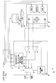
- the system 70 includes a simulator 60 having logic 62, memory 63, and at least one algorithm 66 located in the memory 63.
- the logic 62 is configured to operate responsive to the algorithm 66 stored in the memory 63 of simulator 60 to monitor signals, process signals, and generate simulated signals.
- simulator 60 is a computer. It should be appreciated that in an alternate embodiment, simulator 60 could be implemented in a hardware-only configuration, without software.
- the simulated signals generated by simulator 60 are digital simulated signals. In an alternate embodiment, the simulated signals may be analog signals.
- Simulator 60 is shown coupled to high-speed digital-to-analog converter circuitry 68.
- High-speed digital-to-analog converter circuitry 68 is configured to receive digital simulated signals from simulator 60, convert the digital simulated signals to analog simulated signals, and provide the resulting analog simulated signals to circuitry coupled to high-speed digital-to-analog converter circuitry 68.
- simulator 60 is also shown coupled to analog-to-digital converter circuitry 61, which is also coupled to audio/data processing circuitry 30.
- Analog-to-digital converter circuitry 61 is configured to receive electrical control signals from audio/data processing circuitry 30, convert the received control signals to digital signals, and provide the digital control signals to simulator 60.
- audio/data processing circuitry 30 may provide control signals directly to simulator 60.
- simulator 60 is configured to generate digital simulated signals.
- the digital simulated signals provided by simulator 60 to high-speed digital-to-analog converter circuitry 68 are configured to simulate photo diode signals that would be provided by photodiodes 2-12 of photosensor 11 of CD player 20 of Fig. 1 that is playing a CD 50 during the occurrence of an anomaly.
- the anomaly is a disk defect
- the digital simulated signals provided by simulator 60 are configured to simulate signals provided by a CD photosensor 11 when a test CD 50 having a defect is being played back by the CD player 20 of Fig. 1.
- the anomaly is a physical shock introduced into the CD player 20 of Fig.
- the digital simulated signals provided by simulator 60 are configured to simulate the output of a CD photosensor 11 when a CD player 20 of Fig. 1 playing a CD 50 is exposed to a physical shock, such as, for example, a vibration.
- the digital simulated photosensor signals are created by an algorithm 66 running on simulator 60, and are created based on photosensor data provided by a CD player 20 of Fig. 1 operating under anomaly conditions.
- high-speed digital-to-analog converter circuitry 68 receives the digital simulated photosensor signals, and converts them into analog simulated photosensor signals.
- the resulting waveforms of the analog simulated photosensor signals closely match the analog waveforms of actual photosensor signals that would be provided by a photosensor of a CD player 20 of Fig. 1 playing a CD 50 in an anomaly condition.
- a first simulated photosensor signal S 1 simulates the combined output of the two photo diodes 2 and 6 in the photosensor 11 of CD player 20 of Fig. 1 during an anomaly condition.
- the photo diodes 2 and 6 that are simulated are photo diodes normally providing an output signal representative of both the focus condition of the photosensor 11 of Fig. 1, and audio data detected by the photo diodes 2 and 6 of the photosensor 11.
- the second simulated signal S2 provided by simulator 60 to high-speed digital-to-analog converter circuitry 68 is a signal simulating the combined output of two additional photo diodes 4 and 8 in photosensor 11 of CD player 20 of Fig. 1 during an anomaly condition. These two additional photo diodes 4 and 8 in photosensor 11 of CD player 20 normally provide a combined output signal representative of both the focus condition of the photosensor and audio data detected by the photo diodes 4 and 8 of photosensor 11 of Fig. 1.
- the third simulated signal S3 provided by simulator 60 to high-speed digital-to-analog converter circuitry 68 is a simulated signal representing the output of a fifth photo diode 10 in a photosensor 11 of CD player of Fig. 1 during an anomaly condition.
- This fifth photo diode 10 provides a signal that is representative of the tracking condition of the photosensor 11 of the CD player 20.
- the fourth simulated signal S4 provided by simulator 60 to high-speed digital-to-analog converter circuitry 68 is a signal simulating the output of a sixth photo diode 12 in a photosensor 11 of CD player 20 of Fig. 1 during an anomaly condition.
- This fourth simulated signal S4 is indicative of the tracking state of the photosensor 11 of the CD player 20.
- high-speed digital-to-analog converter circuitry 68 receives the digital simulated signals S1-S4 from simulator 60, and converts the digital simulated signals into analog simulated signals S1-S4. After the analog simulated signals S1-S4 have been converted into analog signals, the signals closely approximate the analog output waveforms of photodiodes 2-12 of photosensor 11 of a CD player 20 of Fig. 1 that is playing a CD in an anomaly condition.
- the first and second analog simulated signals S 1 and S2 include both focus error information and audio information, while the third and fourth analog simulated signals S3 and S4 include tracking error information.
- audio/data processing 30 is processing circuitry configured to process audio and data signals provided by an audio CD player pickup mechanism.
- audio/data processing circuitry 30 is processing circuitry configured to process audio and/or data provided by other optical digital disk player pickup mechanisms.
- Audio/data processing circuitry 30 includes comparator circuitry 33, comparator circuitry 35, audio processing circuitry 36, control signal processing circuitry 38, digital-to-analog converter circuitry 40, and data output circuitry 42. As shown, the first and second analog simulated signals S1 and S2 containing focus and audio information are processed by comparator 33 and audio processing circuitry 36 after being received by audio/data processing circuitry 30.
- the signals processed by audio processing circuitry 36 are HF audio signals formed by combining the first simulated analog signal S 1 with the second simulated analog signal S2 prior to providing the resulting HF audio signal to audio processing circuitry 36.
- Audio processing circuitry 36 processes the HF audio signal formed by combining the first simulated analog signal S 1 with the second simulated analog signal S2 to extract audio information such as, for example, music.
- Audio processing circuitry 36 is also shown coupled to data output circuitry 42.
- the audio information provided by audio processing circuitry 36 is provided to data output circuitry 42, where the audio information is additionally processed and provided to additional circuitry (not shown) to convert the audio information into a format that can be perceived by the human ear.
- the first and second simulated analog signals S 1 and S2 are also input to comparator circuitry 33 of processing circuitry 30.
- Comparator circuitry 33 compares the value of the first and second simulated analog signals S 1 and S2 to determine if they are indicative of a photosensor 11 of Fig. 1 that is out of focus. If the difference between the first and second simulated analog signals S 1 and S2 is approximately zero, there is little or no focus error, and focus adjustment of the pickup mechanism 22 of the CD player 20 of Fig. 1 is not necessary. If, however, there is a difference between the values of the first simulated analog signal S 1 and second simulated analog signal S2, a focus error is present, indicating that adjustment of the pickup mechanism 22 of the CD player 20 may be necessary.
- High-speed digital-to-analog converter circuitry 68 is also shown providing third and fourth simulated analog signals S3 and S4 to audio data processing circuitry 30. More specifically, third and fourth simulated analog signals S3 and S4 are provided to comparator circuitry 35 of audio/data processing circuitry 30, and are compared to determine if there is a difference between the two signals S3 and S4. If there is no difference between the third and fourth simulated analog signals S3 and S4, there is little or no tracking error, and adjustment of the pickup mechanism 22 of the CD player 20 of Fig. 1 is unnecessary. If, however, there is a difference between the value of the third and fourth simulated analog signals S3 and S4, a tracking error is present, and an adjustment of pickup mechanism 22 of the CD player 20 may be necessary.
- Audio/data processing circuitry 30 is also shown including control signal processing circuitry 38.
- Control signal processing circuitry 38 is electrically coupled to comparator circuitry 35 and comparator circuitry 33.
- Control signal processing circuitry 38 is also shown receiving the HF audio signal that is provided to audio processing circuitry 36.
- Control signal processing circuitry 38 is configured to process an electrical signal received from comparator circuitry 35 to determine, based on the value of that signal, if there is a tracking error detected by photosensor 11 of pickup mechanism 22 of the CD player 20 of Fig. 1. If control signal processing circuitry 38 determines, based on a tracking error signal received from comparator circuitry 35, that there is a tracking error present, control signal processing circuitry 38 generates a tracking control signal T1.
- control signal T1 is configured to control a tracking adjustment mechanism of an optical digital disk player, such as, for example, tracking adjustment mechanism 14 of pickup mechanism 22 of CD player 20 of Fig. 1, to adjust the tracking of the optical digital disk player.
- Control signal processing circuitry 38 is also shown receiving a focus error signal from comparator circuitry 33.
- Control signal processing circuitry 38 is configured to evaluate the focus error signal received from comparator circuitry 33 to determine if a focus error is present. If control signal processing circuitry 38 determines that a focus error is present, control signal processing circuitry 38 generates a focus control signal F1.
- control signal F1 is configured to control a focus adjustment mechanism of an optical digital disk player, such as, for example, focus adjustment mechanism 16 of pickup mechanism 22 of CD player 20 of Fig. 1, to adjust the focus of the optical digital disk player.
- Control signal processing circuitry 38 is also shown receiving an HF audio signal that has been provided to audio/data processing circuitry 30 by high-speed digital-to-analog converter circuitry 68. Control signal processing circuitry 38 evaluates the HF audio signal alone, or in combination with, other signals, such as the focus error signal from comparator circuitry 33 and/or the tracking error signal from comparator circuitry 35, to additionally evaluate whether focus, tracking, or other errors are present.
- control signal processing circuitry 38 is also configured to generate a sled adjustment control signal S5.
- control signal S5 is configured to control a sled adjustment mechanism of an optical digital disk player, such as, for example, sled adjustment mechanism 18 of pickup mechanism 22 of CD player 20 of Fig. 1.
- control signal processing circuitry 38 is also configured to generate motor control signals M1.
- control signal M1 is configured to control the speed and direction of rotation of a spindle drive motor, such as, for example, spindle drive motor 46 of CD player 20 of Fig. 1.
- Audio/data processing circuitry 30 is also shown having I/O circuitry 42 for allowing control signals and/or data to be provided to audio/data processing circuitry 30 from external circuitry (not shown), and to allow data and/or control signals to be provided to external circuitry (not shown) from audio/data processing circuitry 30.
- I/O circuitry 42 is shown coupled to control signal processing circuitry 38, audio processing circuitry 36, comparator circuitry 33, and comparator circuitry 35. In this manner, HF audio signals, focus error signals provided by comparator circuitry 33, tracking error signals provided by comparator circuitry 35, and control signals provided by control signal processing circuitry 38 may be monitored by external circuitry coupled to audio/data processing circuitry 30 via I/O circuitry 42. Audio and/or other data provided via I/O circuitry 42 may also be monitored for skip conditions, mute conditions, and other conditions of interest to a user to evaluate how the processing circuitry 30 responds to various anomalies.
- Control signal processing circuitry 38 is also shown coupled to digital-to-analog converter circuitry 40.
- digital-to-analog converter circuitry 40 receives digital control signals M1, F1, T1 and S5 provided by control signal processing circuitry 38, and converts the digital control signals into analog control signals before providing those signals as an output from audio/data processing circuitry 30 to additional circuitry coupled to audio/data processing circuitry 30.
- the system 70 is also shown including driver control circuitry 44 coupled to audio/data processing circuitry 30.
- driver control circuitry 44 is configured to receive control signals provided by audio/data processing circuitry 30, and convert those control signals into analog signals that can be directly used by the devices to which those signals are provided.
- driver control circuitry 44 receives four signals from digital-to-analog converter circuitry 40 of audio/data processing circuitry 30. These signals include motor control signals M1, focus control signals F1, tracking control signals T1, and sled control signals S5.
- the motor control signals M1 provided by digital-to-analog circuitry 40 of audio/data processing circuitry 30 are received by driver circuitry 44 and converted to signal levels and formats directly usable by a spindle drive motor, such as, for example, spindle drive motor 46 of Fig. 1, to control the direction and speed of rotation of spindle drive motor 46.
- a spindle drive motor such as, for example, spindle drive motor 46 of Fig. 1, to control the direction and speed of rotation of spindle drive motor 46.
- Driver control circuitry 44 is also shown receiving tracking control signals T1 from digital-to-analog converter circuitry 40 of audio/data processing circuitry 30.
- Driver control circuitry 44 converts the received analog tracking control signals T1 into control signals configured to be directly used to control a tracking adjustment mechanism, such as, for example, tracking adjustment mechanism 14 of pickup mechanism 22 of Fig. 1, to control the tracking of pickup mechanism 22.
- Driver control circuitry 44 is also shown receiving focus control signals F1 from digital-to-analog converter circuitry 40 of audio/data processing circuitry 30.
- Driver control circuitry 44 receives the analog focus control signals F1, converts the focus control signals F1 into signals configured to be directly used to control a focus adjustment mechanism, such as, for example, the focus adjustment mechanism 16 of pickup mechanism 22 of Fig. 1, to control the focus of pickup mechanism 22.
- Driver circuitry 44 is also shown receiving analog sled control signals S5 from digital-to-analog converter circuitry 40 of audio/data processing circuitry 30.
- Driver circuitry 44 converts the received analog sled control signals S5 into sled control signals S5 configured to be directly used to control the operation of a sled adjustment mechanism, such as sled adjustment mechanism 18 of pickup mechanism 22 of Fig. 1, to control the position of pickup mechanism 22.
- control signals M1, F1, T1 and S5, configured as discussed above, are provided as inputs to analog-to-digital converter circuitry 61, where they are converted into digital form.
- the control signals M1, F1, T1 and S5 are provided directly from audio/data processing circuitry 30 to analog-to-digital converter circuitry 21, without first passing through driver circuitry 44.
- the control signals M1, F1, T1 and S5 are provided directly from audio/data processing circuitry 30 to simulator 60 without passing through driver circuitry 44 or analog-to-digital converter circuitry 61.
- simulator 60 in addition to being configured to provide the digital simulated signals discussed above, is also configured to simulate a response of a tracking adjustment mechanism, focus adjustment mechanism, sled adjustment mechanism, and spindle drive motor to the control signals T1, F1, S5, and M1, respectively, provided by analog-to-digital converter circuitry 61. In this manner, simulator 60 can determine how tracking adjustment mechanisms, focus adjustment mechanisms, sled adjustment mechanisms, and spindle drive motors of optical digital disk players would likely respond to the control signals generated by processing circuitry 30. Based on the determination, adjustments can be made to the processing circuitry 30 to obtain the desired response.
- simulator 60 is also configured to monitor the control signals T1, F1, S5 and M1 provided by analog-to-digital converter circuitry 61. By monitoring these control signals, simulator 60 can determine how processing circuitry 30 is responding to the simulated digital input. By comparing the values of the control signals with the desired values, adjustments can be made to processing circuitry 30 such that the desired control signals occur based on certain simulated digital inputs.
- simulator 60 is also configured to alter the simulated digital signals it is creating based on the simulated response of the mechanism and motors, the values of the control signals, or both. In this manner, real time feedback based on the control signals generated by signal processing circuitry 30 and their impact on simulated mechanism and motors can be used to dynamically adjust the simulated digital signals to help determine the optimal characteristics of signal processing circuitry 30.
- simulator 60 monitors the response of the control signals T1, M1, S5 and F1 to the simulated input signals S1-S4 provided by simulator 60. Simulator 60 can use the monitored values of the control signals to alter the values of the simulated signals S1-S4 provided to audio/data processing circuitry 30 by simulator 60 via high-speed digital-to-analog converter circuitry 68.
- simulator 60 runs a software algorithm 66, which causes simulator 60 to generate digital simulated waveform signals S1-S4.
- Simulated waveform signals S1-S4 are representative of photo diode signals that would be provided by a photosensor 11 of the CD player 20 of Fig. 1 if the CD player 20 encountered an anomaly during the playback of a CD 50.
- algorithm 66 may be configured such that a single anomaly is simulated, multiple anomalies are simulated sequentially, or multiple anomalies are simulated simultaneously by simulator 60.
- the simulated digital waveform signals S1-S4 are converted into analog simulated waveform signals S1-S4 by high-speed digital-to-analog converter circuitry 68. Simulated analog waveform signals S1-S4 are then provided to audio/data processing circuitry 30 for additional processing.
- the simulated analog waveform signals S1-S4 are used to provide HF audio signals, which are decoded by audio processing circuitry 36 to provide audio signals for a user of the system.
- the simulated analog waveform signals are also used to extract focus error information and tracking error information indicative of whether there is a focus and/or tracking error based on the simulated analog waveform signal.
- the HF audio focus error and tracking error signals are provided to control signal processing circuitry 38, which evaluates the signals to determine if there is a focus error, tracking error, and/or other error based on the received simulated analog signals.
- Simulator 60 monitors the values of the focus control signals F1, tracking control signals T1, sled control signals S5, and motor control signals M1 to evaluate the response of processing circuitry 30 to the simulated signals S1-S4 provided by algorithm 66. Simulator 60 may also adjust the value of the simulated signals S1-S4 provided by algorithm 66 based on the value of the monitored control signals F1, T1, M1 and S5. In addition, simulator 60 simulates the response of the various mechanisms and motors to the control signals F1, T1, M1 and S5, monitors these simulated responses, and adjusts the value of the simulated signals S1-S4 provided by algorithm 66 based on the monitored simulated response.
- a user of the system 70 can determine how to optimize system components and/or processing steps and parameters employed in audio/data processing circuitry 30 to improve the response of the CD player 20 to anomalies, such as defects in the CD and/or environmental vibrations, or other environmental factors. This can be accomplished without exposing the system 70 to actual defective disks or vibrations, and can also be accomplished in an automated fashion by configuring simulator 60 to sequence through a number of "anomaly" scenarios without user intervention.
- Fig. 3 generally illustrates a method 100 for evaluating the response of optical digital disk player circuitry to anomalies.
- an optical digital disk player is provided.
- the optical digital disk player is an audio CD player configured to play an audio CD.
- the optical digital disk player is a player capable of optically extracting digital data from an optical digital disk, including, for example, CD-ROM drives, rewritable CD drives, DVD players, and DVD writers.
- an optical digital disk that is an audio CD having anomalies is played in the CD player provided in step 102.
- the anomalies are defects on the surface of the audio CD that is being played, and include, for example, scratches and/or dirt on the surface of the audio CD.
- the optical digital disk having anomalies may include an audio CD, or an optical digital disk other than an audio CD, such as, for example, a DVD.
- a third step 106 of the method 100 signals provided by the pickup mechanism of the audio CD player are monitored while an audio CD having anomalies is being played to identify unique signal characteristics of the pickup mechanism associated with the playback of an audio CD having an anomaly.
- the pickup mechanism signals can be captured electronically, such as, for example, by a digital oscilloscope, so that they can be retrieved for later analysis and review.
- the signals provided by the pickup mechanism of an optical digital disk player are monitored while an optical digital disk other than an audio CD having anomalies is being played to identify unique signal characteristics of the pickup mechanism associated with the playback of an optical digital disk having an anomaly.
- simulator circuitry is coupled to optical digital disk processing circuitry configured to process audio and/or data provided by an optical digital disk player pickup mechanism.
- the optical digital disk processing circuitry is audio CD processing circuitry configured to process audio and/or data provided by an audio CD player pickup mechanism.
- a seventh step 114 of the method 100 the processing circuitry to which the simulated pickup mechanism signals have been provided generates control signals, based on the simulated pickup mechanism signals.
- the control signals are configured to control motors and/or mechanisms of optical digital disk players.
- the control signals generated include tracking, focus, sled and motor control signals.
- control signals are provided to the simulator circuitry.
- control signals are first provided to analog-to-digital converter circuitry prior to being provided to the simulator circuitry.
- the simulated pickup mechanism signals are modified by the simulator circuitry based on the control signals.
- the simulator circuitry simulates the response of a pickup mechanism of an optical digital disk player to the control signals.
- the simulator circuitry simulates the response of a pickup mechanism of an audio CD player to the control signals.
- the simulated pickup mechanism signals are modified based on the simulated response of the pickup mechanism.
- Fig. 4 generally illustrates a method 200 for evaluating the response of optical digital disk player circuitry to anomalies.
- an optical digital disk player is provided.
- the optical digital disk player is an audio CD player configured to play an audio CD.
- the optical digital disk player is a player capable of optically extracting digital data from an optical digital disk, including, for example, CD-ROM drives, rewritable CD drives, DVD players, and DVD writers.
- an optical digital disk that is an audio CD is played in the CD player provided in step 02 while the CD player is subjected to anomalies.
- the anomalies are physical vibrations introduced into the CD player while it is playing an audio CD.
- the anomalies are physical vibrations introduced into the optical digital disk player while it is playing an optical digital disk.
- a third step 206 of the method 200 signals provided by the pickup mechanism of the audio CD player are monitored while the audio CD player is subjected to physical vibrations during playback of an audio CD to identify unique signal characteristics of the pickup mechanism associated with the playback of an audio CD in the audio CD player during exposure to physical vibrations.
- the pickup mechanism signals can be captured electronically, such as, for example, by a digital oscilloscope, so that they can be retrieved for later analysis and review.
- the signals provided by the pickup mechanism of an optical digital disk player other than an audio CD player are monitored while the optical digital disk player is subjected to physical vibrations during playback of an optical digital disk to identify unique signal characteristics of the pickup mechanism associated with the playback of an optical digital disk in the optical digital disk player during exposure to physical vibrations.
- simulator circuitry is coupled to optical digital disk processing circuitry configured to process audio and/or data provided by an optical digital disk player pickup mechanism.
- the optical digital disk processing circuitry is audio CD processing circuitry configured to process audio and/or data provided by an audio CD player pickup mechanism.
- simulated pickup mechanism signals are created by the simulator circuitry, such that the simulated pickup mechanism signals substantially resemble pickup mechanism signals generated by an optical digital disk player playing an optical digital disk during exposure to an anomaly such as a vibration.
- the simulated pickup mechanism signals substantially resemble pickup mechanism signals generated by an audio CD player playing an audio CD during an anomaly such as a vibration.
- the simulated pickup mechanism signals are provided to the processing circuitry.
- a seventh step 214 of the method 200 the processing circuitry to which the simulated pickup mechanism signals have been provided generates control signals, based on the simulated pickup mechanism signals.
- the control signals are configured to control motors and/or mechanisms of optical digital disk players.
- the control signals generated include tracking, focus, sled and motor control signals.
- control signals are provided to the simulator circuitry.
- control signals are first provided to analog-to-digital converter circuitry prior to being provided to the simulator circuitry.
- the simulated pickup mechanism signals are modified by the simulator circuitry based on the control signals.
- the simulator circuitry simulates the response of a pickup mechanism of an optical digital disk player to the control signals.
- the simulator circuitry simulates the response of a pickup mechanism of an audio CD player to the control signals.
- the simulated pickup mechanism signals are modified based on the simulated response of the pickup mechanism.
- the invention advantageously provides methods 100 and 200, and a system 70 for evaluating the response of an optical digital disk player to anomalies encountered by the optical digital disk player during playback of an optical digital disk.
- the methods and system accomplish this by using simulated input signals, rather than by requiring the use of fragile defect optical digital disks, and rather than exposing the optical digital disks and/or optical digital disk player to potentially damaging physical anomalies, such as vibration.
- the method and system also advantageously provide for testing the response of optical digital disk players to multiple anomalies without requiring multiple defect optical digital disks to be manually swapped in and out of optical digital disk players. The above advantages can provide for more efficient, cost-effective testing of optical digital disk players.
Landscapes
- Engineering & Computer Science (AREA)
- Signal Processing (AREA)
- Optical Recording Or Reproduction (AREA)
- Signal Processing For Digital Recording And Reproducing (AREA)
- Measurement Of Mechanical Vibrations Or Ultrasonic Waves (AREA)
Applications Claiming Priority (1)
| Application Number | Priority Date | Filing Date | Title |
|---|---|---|---|
| US11/542,956 US7668058B2 (en) | 2006-10-04 | 2006-10-04 | Method and system for evaluating CD player response to vibration during playback of a CD |
Publications (2)
| Publication Number | Publication Date |
|---|---|
| EP1909285A2 true EP1909285A2 (de) | 2008-04-09 |
| EP1909285A3 EP1909285A3 (de) | 2014-01-01 |
Family
ID=38704460
Family Applications (1)
| Application Number | Title | Priority Date | Filing Date |
|---|---|---|---|
| EP07117406.4A Withdrawn EP1909285A3 (de) | 2006-10-04 | 2007-09-27 | Verfahren und System zur Messung der Reaktion eines CD-Players auf Vibrationen während des Abspielens einer CD |
Country Status (2)
| Country | Link |
|---|---|
| US (2) | US7668058B2 (de) |
| EP (1) | EP1909285A3 (de) |
Families Citing this family (1)
| Publication number | Priority date | Publication date | Assignee | Title |
|---|---|---|---|---|
| CN109803640B (zh) | 2016-08-10 | 2022-01-04 | 赛特瑞恩股份有限公司 | 稳定的液体抗流感病毒抗体医药调配物 |
Family Cites Families (12)
| Publication number | Priority date | Publication date | Assignee | Title |
|---|---|---|---|---|
| JPH01206232A (ja) * | 1988-02-12 | 1989-08-18 | Nippon Telegr & Teleph Corp <Ntt> | 光ディスク用機械特性試験機 |
| JP3102759B2 (ja) * | 1996-02-05 | 2000-10-23 | 富士通テン株式会社 | 光ディスク再生装置の検査方法 |
| US5923487A (en) * | 1997-06-05 | 1999-07-13 | Maxtor Corporation | Integrated shock sensing device |
| JP2000057713A (ja) * | 1998-08-05 | 2000-02-25 | Mitsubishi Electric Corp | 光ディスクの欠陥管理方法、光ディスク装置、及び、光ディスク |
| JP3931452B2 (ja) * | 1998-10-30 | 2007-06-13 | ソニー株式会社 | 光ディスク装置の制御特性評価装置及び光ディスク装置 |
| JP3768415B2 (ja) * | 2001-05-30 | 2006-04-19 | 富士通株式会社 | 書き込み/消去方法及び記憶装置 |
| JP2003173620A (ja) * | 2001-12-04 | 2003-06-20 | Tdk Corp | 信号処理シミュレーションシステム及び信号処理シミュレーション方法 |
| US20030128639A1 (en) * | 2001-12-18 | 2003-07-10 | Matsushita Elec. Ind. Co. Ltd. | Optical disc device |
| US7623419B2 (en) * | 2003-01-31 | 2009-11-24 | Panasonic Corporation | Method and apparatus for measuring off-track detection sensitivity |
| US20050180276A1 (en) * | 2004-02-17 | 2005-08-18 | Canon Kabushiki Kaisha | Optical information recording and reproducing apparatus |
| US7859965B2 (en) * | 2005-04-08 | 2010-12-28 | Pioneer Corporation | Recording device and method, reproducing device and method, recording/reproducing device and method, and computer program |
| JP2007207390A (ja) * | 2006-02-06 | 2007-08-16 | Hitachi Ltd | 光ディスク装置及び試し書き方法 |
-
2006
- 2006-10-04 US US11/542,956 patent/US7668058B2/en not_active Ceased
-
2007
- 2007-09-27 EP EP07117406.4A patent/EP1909285A3/de not_active Withdrawn
-
2012
- 2012-02-23 US US13/403,410 patent/USRE44714E1/en active Active
Also Published As
| Publication number | Publication date |
|---|---|
| USRE44714E1 (en) | 2014-01-21 |
| US20080086280A1 (en) | 2008-04-10 |
| EP1909285A3 (de) | 2014-01-01 |
| US7668058B2 (en) | 2010-02-23 |
Similar Documents
| Publication | Publication Date | Title |
|---|---|---|
| US8531931B2 (en) | Optical disk inspecting apparatus and method | |
| USRE44714E1 (en) | CD response to vibration during playback of a CD | |
| US7760598B2 (en) | Method and system for evaluating CD player response to anomalies in a CD | |
| JP3102759B2 (ja) | 光ディスク再生装置の検査方法 | |
| US7209417B2 (en) | Method of and apparatus for recording data on defective optical storage media and computer readable medium storing the method | |
| CN100395826C (zh) | 光盘片的缺陷区块决定方法以及排除缺陷区块写入方法 | |
| JP5008461B2 (ja) | 障害情報記憶装置および障害情報記憶方法 | |
| KR100392398B1 (ko) | 픽업 유니트 검사장치 | |
| US20050286378A1 (en) | Data writing method | |
| CN101727945A (zh) | 光盘检查装置及检查方法 | |
| KR20030015355A (ko) | 광디스크 드라이브 장치의 재생 제어 방법 및 그 광디스크드라이브 장치 | |
| JP3059334U (ja) | 追記型光ディスク記録装置 | |
| JP4104573B2 (ja) | リードアウトエリア開始位置復元方法およびディスク再生装置 | |
| KR100455836B1 (ko) | 섹터값 리드시 에러방지 방법 | |
| JP3398112B2 (ja) | 光ディスク再生装置の検査装置 | |
| CN100388361C (zh) | 驱动力量参数产生方法 | |
| KR100706472B1 (ko) | 광 디스크 플레이어의 데이터 기록 방법 | |
| JP2005158107A (ja) | 光ディスク記録再生装置の信号処理回路 | |
| JP2000187861A (ja) | 光情報記録媒体の再生装置 | |
| KR19990038613A (ko) | 광 디스크 판별장치 및 방법 | |
| JP2000105975A (ja) | 光ディスク記録再生装置の記録制御方法 | |
| CN1428768A (zh) | 拾取器检测装置 | |
| KR20030073235A (ko) | 광기록재생기의 결함영역 판별 방법 및 결함관리 방법 | |
| KR20030013725A (ko) | 불량 광디스크 장치 판별방법 | |
| KR20010095390A (ko) | 광디스크 구동방법 |
Legal Events
| Date | Code | Title | Description |
|---|---|---|---|
| PUAI | Public reference made under article 153(3) epc to a published international application that has entered the european phase |
Free format text: ORIGINAL CODE: 0009012 |
|
| AK | Designated contracting states |
Kind code of ref document: A2 Designated state(s): AT BE BG CH CY CZ DE DK EE ES FI FR GB GR HU IE IS IT LI LT LU LV MC MT NL PL PT RO SE SI SK TR |
|
| AX | Request for extension of the european patent |
Extension state: AL BA HR MK RS |
|
| RAP1 | Party data changed (applicant data changed or rights of an application transferred) |
Owner name: TAB TWO LIMITED LIABILITY COMPANY |
|
| PUAL | Search report despatched |
Free format text: ORIGINAL CODE: 0009013 |
|
| AK | Designated contracting states |
Kind code of ref document: A3 Designated state(s): AT BE BG CH CY CZ DE DK EE ES FI FR GB GR HU IE IS IT LI LT LU LV MC MT NL PL PT RO SE SI SK TR |
|
| AX | Request for extension of the european patent |
Extension state: AL BA HR MK RS |
|
| RIC1 | Information provided on ipc code assigned before grant |
Ipc: G11B 19/04 20060101ALI20131126BHEP Ipc: G11B 27/36 20060101AFI20131126BHEP Ipc: G11B 20/18 20060101ALI20131126BHEP |
|
| 17P | Request for examination filed |
Effective date: 20140701 |
|
| RBV | Designated contracting states (corrected) |
Designated state(s): AT BE BG CH CY CZ DE DK EE ES FI FR GB GR HU IE IS IT LI LT LU LV MC MT NL PL PT RO SE SI SK TR |
|
| RBV | Designated contracting states (corrected) |
Designated state(s): AT BE BG CH CY CZ DE DK EE ES FI FR GB GR HU IE IS IT LI LT LU LV MC MT NL PL PT RO SE SI SK TR |
|
| AKX | Designation fees paid |
Designated state(s): DE FR GB |
|
| GRAP | Despatch of communication of intention to grant a patent |
Free format text: ORIGINAL CODE: EPIDOSNIGR1 |
|
| INTG | Intention to grant announced |
Effective date: 20150226 |
|
| STAA | Information on the status of an ep patent application or granted ep patent |
Free format text: STATUS: THE APPLICATION IS DEEMED TO BE WITHDRAWN |
|
| 18D | Application deemed to be withdrawn |
Effective date: 20150709 |