EP1908703B1 - Cartridge piston - Google Patents
Cartridge piston Download PDFInfo
- Publication number
- EP1908703B1 EP1908703B1 EP07115890A EP07115890A EP1908703B1 EP 1908703 B1 EP1908703 B1 EP 1908703B1 EP 07115890 A EP07115890 A EP 07115890A EP 07115890 A EP07115890 A EP 07115890A EP 1908703 B1 EP1908703 B1 EP 1908703B1
- Authority
- EP
- European Patent Office
- Prior art keywords
- cartridge piston
- cartridge
- accordance
- wall
- piston
- Prior art date
- Legal status (The legal status is an assumption and is not a legal conclusion. Google has not performed a legal analysis and makes no representation as to the accuracy of the status listed.)
- Active
Links
Images

Classifications
-
- B—PERFORMING OPERATIONS; TRANSPORTING
- B05—SPRAYING OR ATOMISING IN GENERAL; APPLYING FLUENT MATERIALS TO SURFACES, IN GENERAL
- B05C—APPARATUS FOR APPLYING FLUENT MATERIALS TO SURFACES, IN GENERAL
- B05C17/00—Hand tools or apparatus using hand held tools, for applying liquids or other fluent materials to, for spreading applied liquids or other fluent materials on, or for partially removing applied liquids or other fluent materials from, surfaces
-
- B—PERFORMING OPERATIONS; TRANSPORTING
- B65—CONVEYING; PACKING; STORING; HANDLING THIN OR FILAMENTARY MATERIAL
- B65D—CONTAINERS FOR STORAGE OR TRANSPORT OF ARTICLES OR MATERIALS, e.g. BAGS, BARRELS, BOTTLES, BOXES, CANS, CARTONS, CRATES, DRUMS, JARS, TANKS, HOPPERS, FORWARDING CONTAINERS; ACCESSORIES, CLOSURES, OR FITTINGS THEREFOR; PACKAGING ELEMENTS; PACKAGES
- B65D83/00—Containers or packages with special means for dispensing contents
- B65D83/76—Containers or packages with special means for dispensing contents for dispensing fluent contents by means of a piston
-
- A—HUMAN NECESSITIES
- A61—MEDICAL OR VETERINARY SCIENCE; HYGIENE
- A61M—DEVICES FOR INTRODUCING MEDIA INTO, OR ONTO, THE BODY; DEVICES FOR TRANSDUCING BODY MEDIA OR FOR TAKING MEDIA FROM THE BODY; DEVICES FOR PRODUCING OR ENDING SLEEP OR STUPOR
- A61M5/00—Devices for bringing media into the body in a subcutaneous, intra-vascular or intramuscular way; Accessories therefor, e.g. filling or cleaning devices, arm-rests
- A61M5/178—Syringes
- A61M5/31—Details
- A61M5/315—Pistons; Piston-rods; Guiding, blocking or restricting the movement of the rod or piston; Appliances on the rod for facilitating dosing ; Dosing mechanisms
- A61M5/31511—Piston or piston-rod constructions, e.g. connection of piston with piston-rod
-
- B—PERFORMING OPERATIONS; TRANSPORTING
- B05—SPRAYING OR ATOMISING IN GENERAL; APPLYING FLUENT MATERIALS TO SURFACES, IN GENERAL
- B05C—APPARATUS FOR APPLYING FLUENT MATERIALS TO SURFACES, IN GENERAL
- B05C17/00—Hand tools or apparatus using hand held tools, for applying liquids or other fluent materials to, for spreading applied liquids or other fluent materials on, or for partially removing applied liquids or other fluent materials from, surfaces
- B05C17/005—Hand tools or apparatus using hand held tools, for applying liquids or other fluent materials to, for spreading applied liquids or other fluent materials on, or for partially removing applied liquids or other fluent materials from, surfaces for discharging material from a reservoir or container located in or on the hand tool through an outlet orifice by pressure without using surface contacting members like pads or brushes
- B05C17/00576—Hand tools or apparatus using hand held tools, for applying liquids or other fluent materials to, for spreading applied liquids or other fluent materials on, or for partially removing applied liquids or other fluent materials from, surfaces for discharging material from a reservoir or container located in or on the hand tool through an outlet orifice by pressure without using surface contacting members like pads or brushes characterised by the construction of a piston as pressure exerting means, or of the co-operating container
- B05C17/00579—Hand tools or apparatus using hand held tools, for applying liquids or other fluent materials to, for spreading applied liquids or other fluent materials on, or for partially removing applied liquids or other fluent materials from, surfaces for discharging material from a reservoir or container located in or on the hand tool through an outlet orifice by pressure without using surface contacting members like pads or brushes characterised by the construction of a piston as pressure exerting means, or of the co-operating container comprising means for allowing entrapped air to escape to the atmosphere
-
- B—PERFORMING OPERATIONS; TRANSPORTING
- B65—CONVEYING; PACKING; STORING; HANDLING THIN OR FILAMENTARY MATERIAL
- B65D—CONTAINERS FOR STORAGE OR TRANSPORT OF ARTICLES OR MATERIALS, e.g. BAGS, BARRELS, BOTTLES, BOXES, CANS, CARTONS, CRATES, DRUMS, JARS, TANKS, HOPPERS, FORWARDING CONTAINERS; ACCESSORIES, CLOSURES, OR FITTINGS THEREFOR; PACKAGING ELEMENTS; PACKAGES
- B65D83/00—Containers or packages with special means for dispensing contents
-
- A—HUMAN NECESSITIES
- A61—MEDICAL OR VETERINARY SCIENCE; HYGIENE
- A61M—DEVICES FOR INTRODUCING MEDIA INTO, OR ONTO, THE BODY; DEVICES FOR TRANSDUCING BODY MEDIA OR FOR TAKING MEDIA FROM THE BODY; DEVICES FOR PRODUCING OR ENDING SLEEP OR STUPOR
- A61M5/00—Devices for bringing media into the body in a subcutaneous, intra-vascular or intramuscular way; Accessories therefor, e.g. filling or cleaning devices, arm-rests
- A61M5/178—Syringes
- A61M5/31—Details
- A61M5/315—Pistons; Piston-rods; Guiding, blocking or restricting the movement of the rod or piston; Appliances on the rod for facilitating dosing ; Dosing mechanisms
- A61M5/31511—Piston or piston-rod constructions, e.g. connection of piston with piston-rod
- A61M5/31513—Piston constructions to improve sealing or sliding
Definitions
- the invention relates to a cartridge piston according to the preamble of claim 1, as from DE 200 10417 U1 known.
- cartridge pistons are from the EP 1 165 400 B1 known. There are provided between the outer wall and an inner annular support body of the cartridge piston star-shaped radial connecting webs. The connecting webs have lateral ribs and run almost over the entire height of the cartridge piston. How special FIG. 1 of the EP 1 165 400 B 1 shows, the connecting webs are set back slightly only in the region of an outwardly inclined Abstützlippe on the underside of the cartridge piston relative to the lower end face, so that there is a stable connection between the inner annular support body and the outer wall. As a result, such cartridge piston are relatively stiff and can be used without major deformations in cartridges and moved to express the cartridges using Eindschst Schemeeln. Further examples of such pistons are from the EP 1514 812 A1 known.
- Cartridges with such cartridge pistons are usually used for discharging the materials contained in the cartridges in specially provided Ausd Wegpistolen with a force acting on the cartridge piston push-in ram.
- the indenting rams can deflect when pressed against the cartridge axis, so that the cartridge pistons are pressed in on one side or obliquely. This can lead to sealing problems with stiff cartridge pistons.
- the object of the invention is to provide a cartridge piston of the type mentioned, which ensures a good sealing even with one-sided or slate load by a push-in ram.
- a stiffening body connected to the connecting webs is provided between the outer wall and the inner supporting body of the cartridge piston, wherein the connecting webs on the underside of the cartridge piston between the outer wall and the stiffening body have a gap reaching at least half the height of the cartridge piston.
- the piston core may tilt, while the outer wall is aligned with the sealing and supporting lips of the cartridge.
- the sealing function of the cartridge piston can be maintained even with larger misalignments or one-sided loads on the push-in ram.
- the gap in the connecting webs tapers in a wedge shape from the underside of the cartridge piston upwards.
- the cartridge piston has on its upper side an upwardly open edge-side annular groove.
- one or more further stiffening bodies can also be arranged, especially with larger cartridge pistons.
- the inner support body may be executed in an expedient hollow-cylindrical design and contain a vent valve for the trapped between the filling material and the Kartsuchenkolben air.
- the inner support body can also be designed as a solid core as the starting point of the outer wall radially extending star-shaped connecting webs.
- Cartridge pistons 1 shown in different views are intended as ejection pistons for cartridges used for storing and dispensing a wide variety of materials, such as adhesives, sealants and the like.
- the cartridges are used for discharging usually in commercial Ausdrückpistolen.
- These ejection pistols contain a push-in ram, by means of which the cartridge piston 1 is pressed into the associated cartridge and thus the material in the cartridge can be expressed via a discharge opening of the cartridge.
- the cartridge piston 1 includes an outer wall 2 with a radially outwardly projecting upper edge 3 on and a likewise radially outwardly projecting lower edge 4 on the underside.
- a sealing edge 5 is formed at the upper edge 3.
- the lower edge 4 forms a support lip for guiding the cartridge piston 1 within the cartridge.
- the outer diameter of the lower edge 4 and the upper edge 3 with the sealing edge 5 is greater than the inner diameter of the associated cartridge. As a result, the sealing lip and the supporting lip are biased.
- the cartridge piston 1 radially inside the outer wall 2, a central inner hollow cylindrical support body 6 and radial connecting webs 7, which extend starting from the hollow cylindrical support body 6 star-shaped to the outer wall 2 and connect the outer wall 2 with the support body 6.
- the cartridge piston 2 contains an in FIG. 3 recognizable top surface 8.
- stiffening body 9 is provided between the inner support body 6 and the outer wall 2 and is connected to the connecting webs 7 .
- the stiffening body 9 is annular in the embodiment shown and is formed by ring-segment-shaped stiffening webs 10 between the connecting webs 7.
- the stiffening webs 10 can also run in a straight line and the stiffening body 9 can be square or have another suitable shape.
- the cartridge piston 1 contains at its upper side facing the cartridge contents an upwardly open, in cross-section V-shaped outer annular groove 12 and a coaxial inner annular groove 13.
- the outer annular groove 12 ensures that the upper edge 3 with the sealing lip 5 side is flexible and can invest in the inner wall of a cartridge.
- the outer annular groove 12 ensures that through the upper Edge 3 formed with the sealing edge 5 sealing lip is pressed by the pressure acting on the cartridge piston pressure of the cartridge contents radially outwardly against the wall of the cartridge during the extrusion of the cartridge.
- the between the gap 11 and the upper annular groove 12 according to FIG. 4 remaining web 14 is relatively narrow, so that the outer wall 2 is connected to the stable cartridge core in the manner of a rotary joint and thus extremely flexible. This allows the outer wall of the cartridge piston to optimally adapt to the inner wall of the cartridge.
- a cover plate 15 is fastened with an outer edge 16 which engages in the outer annular groove 12 and is angled downwards, and an inner annular web 17 engaging in the inner annular groove 13.
- Locking lugs 18 and locking grooves 19 are provided through which the cover 15 is held via a latching connection on the cartridge piston 1.
- the cover 15 consists for example of polyamide or another, resistant to the cartridge contents material, so as to protect the example of polyethylene or other soft plastic cartridge piston 2.
- a downwardly projecting conical pin 20 is formed axially movable in the middle of the cover 15.
- the conical pin 20 protrudes into a through hole 21 of the inner support body 6 and forms with a valve lip 22 a vent valve.
- On the top surface 8 of the cartridge piston 2 are interrupted spacer webs or spacer cams 23, by which the cover plate 15 is kept at a predetermined small gap 24 spaced from the top surface 8.
- the conical pin 20 is pressed during insertion of the cartridge piston 2 into the cartridge by a corresponding approach to a tool from below, so that the vent valve opens.
- FIGS. 5 to 7 a further embodiment of a cartridge piston is shown.
- This embodiment differs from the first exemplary embodiment only in that a further annular stiffening body 25 concentric therewith is provided radially inside the annular stiffening body 9. Also, the stiffening body 25 is formed by annular segment-shaped stiffening webs 26 between the star-shaped connecting webs. Otherwise, the cartridge piston has a construction corresponding to the first exemplary embodiment, so that components corresponding to one another are also provided with the same reference numerals.
Landscapes
- Engineering & Computer Science (AREA)
- Mechanical Engineering (AREA)
- Health & Medical Sciences (AREA)
- Life Sciences & Earth Sciences (AREA)
- General Health & Medical Sciences (AREA)
- Biomedical Technology (AREA)
- Heart & Thoracic Surgery (AREA)
- Hematology (AREA)
- Vascular Medicine (AREA)
- Animal Behavior & Ethology (AREA)
- Anesthesiology (AREA)
- Public Health (AREA)
- Veterinary Medicine (AREA)
- Coating Apparatus (AREA)
- Containers And Packaging Bodies Having A Special Means To Remove Contents (AREA)
- Pistons, Piston Rings, And Cylinders (AREA)
- Packaging Of Annular Or Rod-Shaped Articles, Wearing Apparel, Cassettes, Or The Like (AREA)
Abstract
Description
Die Erfindung betrifft einen Kartuschenkolben nach dem Oberbegriff des Anspruchs 1, wie aus
Weitere Kartuschenkolben sind aus der
Kartuschen mit derartigen Kartuschenkolben werden zum Austrag der in den Kartuschen befindlichen Materialien üblicherweise in speziell dafür vorgesehene Ausdrückpistolen mit einem auf den Kartuschenkolben wirkenden Eindrückstößel eingesetzt. Besonders bei kostengünstigen Ausdrückpistolen können die Eindrückstößel jedoch beim Eindrücken gegenüber der Kartuschenachse ausweichen, so dass die Kartuschenkolben einseitig bzw. schief eingedrückt werden. Dies kann bei steifen Kartuschenkolben zu Dichtproblemen führen.Cartridges with such cartridge pistons are usually used for discharging the materials contained in the cartridges in specially provided Ausdrückpistolen with a force acting on the cartridge piston push-in ram. However, especially with low-cost ejection pistons, the indenting rams can deflect when pressed against the cartridge axis, so that the cartridge pistons are pressed in on one side or obliquely. This can lead to sealing problems with stiff cartridge pistons.
Aufgabe der Erfindung ist es, einen Kartuschenkolben der eingangs genannten Art zu schaffen, der auch bei einseitiger bzw. schiefer Belastung durch einen Eindrückstößel ein gutes Abdichtverhalten gewährleistet.The object of the invention is to provide a cartridge piston of the type mentioned, which ensures a good sealing even with one-sided or slate load by a push-in ram.
Diese Aufgabe wird durch einen Kartuschenkolben mit den Merkmalen des Anspruchs 1 gelöst. Zweckmäßige Weiterbildungen und vorteilhafte Ausführungsformen der Erfindung sind Gegenstand der Unteransprüche.This object is achieved by a cartridge piston with the features of
Bei dem erfindungsgemäßen Kartuschenkolben ist zwischen der Außenwand und dem inneren Stützkörper des Kartuschenkolbens ein mit den Verbindungsstegen verbundener Versteifungskörper vorgesehen, wobei die Verbindungsstege an der Unterseite des Kartuschenkolbens zwischen der Außenwand und dem Versteifungskörper einen mindestens bis zur halben Höhe des Kartuschenkolbens reichenden Spalt aufweisen. Durch die den inneren Stützkörper und den mit diesem verrippten Versteifungskörper wird ein sehr steifer Kolbenkern geschaffen, der den Druck des Mediums ohne Deformation auf den Eindruckstößel übertragen kann. Die Außenwand des Kartuschenkolbens mit den Dicht- bzw. Abstützlippen ist aufgrund der Spalte in den Verbindungsstegen dagegen äußerst flexibel an dem Kolbenkern angelenkt, so dass sich die Dicht- und Abstützlippen auch dann flexibel an eine Kartuschenwand anpassen können, wenn die Kolbenauflage um einen Winkel geneigt ist. Bei einer z.B. durch Schiefstellung oder exzentrisches Drücken eines Eindrückstößels bedingten Schrägstellung des Kolbens kann sich der Kolbenkern neigen, während sich die Außenwand mit den Dicht- und Abstützlippen der Kartusche angleicht. Dadurch kann die Abdichtfunktion des Kartuschenkolbens selbst bei größeren Schiefstellungen oder einseitigen Belastungen des Eindrückstößels beibehalten werden.In the cartridge piston according to the invention, a stiffening body connected to the connecting webs is provided between the outer wall and the inner supporting body of the cartridge piston, wherein the connecting webs on the underside of the cartridge piston between the outer wall and the stiffening body have a gap reaching at least half the height of the cartridge piston. By the inner support body and the ribbed with this stiffening body, a very stiff piston core is created, which can transmit the pressure of the medium without deformation on the impression ram. The outer wall of the cartridge piston with the sealing or supporting lips, however, due to the gap in the connecting webs hinged extremely flexible on the piston core, so that the sealing and supporting lips can also adapt flexibly to a cartridge wall, when the piston pad inclined at an angle is. At a e.g. skewing or eccentric pressing of a push-in plunger causes skewing of the piston, the piston core may tilt, while the outer wall is aligned with the sealing and supporting lips of the cartridge. As a result, the sealing function of the cartridge piston can be maintained even with larger misalignments or one-sided loads on the push-in ram.
In einer besonders zweckmäßigen Ausführung verjüngt sich der Spalt in den Verbindungsstegen von der Unterseite des Kartuschenkolbens nach oben hin keilförmig. Dadurch ist auch die Abstützlippe in radialer Richtung äußerst flexibel und kann radial stärker vorgespannt werden, ohne dabei große Reibungskräfte zu erzeugen.In a particularly expedient embodiment, the gap in the connecting webs tapers in a wedge shape from the underside of the cartridge piston upwards. As a result, the Abstützlippe in the radial direction is extremely flexible and can be biased radially stronger, without generating large frictional forces.
In einer weiteren vorteilhaften Ausgestaltung weist der Kartuschenkolben auf seiner Oberseite eine nach oben offene randseitige Ringnut auf. Zwischen der Ringnut und dem Spalt in den Verbindungsstegen verbleibt somit nur noch ein relativ schmaler Steg zur Außenwand hin, so dass die Außenwand am stabilen Kartuschenkern in Art eines Drehgelenks und damit äußerst flexibel angebunden ist.In a further advantageous embodiment, the cartridge piston has on its upper side an upwardly open edge-side annular groove. Thus, only a relatively narrow web remains between the annular groove and the gap in the connecting webs to the outer wall, so that the outer wall is connected to the stable cartridge core in the manner of a rotary joint and thus extremely flexible.
Radial innerhalb des in der Nähe der Außenwand angeordneten Versteifungskörpers können besonders bei größeren Kartuschenkolben auch einer oder mehrere weitere Versteifungskörper angeordnet sein.Radially within the stiffening body arranged in the vicinity of the outer wall, one or more further stiffening bodies can also be arranged, especially with larger cartridge pistons.
Der innere Stützkörper kann in einer zweckmäßigen Ausführung hohlzylindrisch ausgeführt sein und ein Entlüftungsventil für die zwischen der Füllmasse und dem Kartsuchenkolben eingeschlossene Luft enthalten. Der innere Stützkörper kann aber auch als massiver Kern als Ausgangspunkt der zur Außenwand sternförmig verlaufenden radialen Verbindungsstege ausgeführt sein.The inner support body may be executed in an expedient hollow-cylindrical design and contain a vent valve for the trapped between the filling material and the Kartsuchenkolben air. The inner support body can also be designed as a solid core as the starting point of the outer wall radially extending star-shaped connecting webs.
Weitere Besonderheiten und Vorzüge der Erfindung ergeben sich aus der folgenden Beschreibung bevorzugter Ausführungsbeispiele anhand der Zeichnungen. Es zeigen:
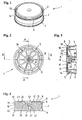
Figur 1- einen erfindungsgemäßen Kartuschenkolben in einer Perspektive;
Figur 2- den Kartuschenkolben von
Figur 1 Figur 3- eine Schnittansicht entlang der Linien A-A von
Figur 2 - Figur 4
- eine Schnittansicht entlang der Linien B-B von
Figur 2 Figur 5- einen weiteren erfindungsgemäßen Kartuschenkolben in einer Unteransicht;
- Figur 6
- eine Schnittansicht entlang der Linien A-A von
Figur 5 Figur 7- eine Schnittansicht entlang der Linien B-B von
Figur 5
- FIG. 1
- a cartridge piston according to the invention in a perspective;
- FIG. 2
- the cartridge piston of
FIG. 1 in a bottom view; - FIG. 3
- a sectional view along the lines AA of
FIG. 2 ; - FIG. 4
- a sectional view taken along the lines BB of
FIG. 2 ; - FIG. 5
- a further cartridge piston according to the invention in a bottom view;
- FIG. 6
- a sectional view along the lines AA of
FIG. 5 and - FIG. 7
- a sectional view taken along the lines BB of
FIG. 5 ,
Der in den
Der Kartuschenkolben 1 enthält eine Außenwand 2 mit einem radial nach außen vorstehenden oberen Rand 3 an der und einem ebenfalls radial nach außen vorstehenden unteren Rand 4 an der Unterseite. An dem oberen Rand 3 ist eine Dichtkante 5 angeformt. Durch den oberen Rand 3 mit der Dichtkante 5 wird eine Dichtlippe zur Abdichtung des Kartuschenkolbens 1 gegenüber der Innenwand einer Kartusche gebildet. Der untere Rand 4 bildet eine Abstützlippe zur Führung des Kartuschenkolbens 1 innerhalb der Kartusche. Der Außendurchmesser des unteren Rands 4 und des oberen Rands 3 mit der Dichtkante 5 ist größer als der Innendurchmesser der dazugehörigen Kartusche. Dadurch sind die Dichtlippe und die Abstützlippe vorgespannt.The
Wie besonders aus den
Aus den
Der Kartuschenkolben 1 enthält an seiner zum Kartuscheninhalt gewandten Oberseite randseitig eine nach oben offene, im Querschnitt V-förmige äußere Ringnut 12 und eine dazu koaxiale innere Ringnut 13. Durch die äußere Ringnut 12 wird gewährleistet, dass der obere Rand 3 mit der Dichtlippe 5 seitlich flexibel ist und sich an die Innenwand einer Kartusche anlegen kann. Außerdem sorgt die äußere Ringnut 12 dafür, dass die durch den oberen Rand 3 mit der Dichtkante 5 gebildete Dichtlippe durch den beim Auspressen der Kartusche auf den Kartuschenkolben wirkenden Druck des Kartuscheninhalts radial nach außen an die Wand der Kartusche angedrückt wird. Der zwischen dem Spalt 11 und der oberen Ringnut 12 gemäß
Auf der Oberseite des Kartuschenkolbens 1 ist eine Abdeckscheibe 15 mit einem in die äußere Ringnut 12 eingreifenden, nach unten abgewinkelten äußeren Rand 16 und einem in die innere Ringnut 13 eingreifenden inneren Ringsteg 17 befestigt. An dem nach unten abgewinkelten äußeren Rand 16 und dem inneren Ringsteg 17 der Abdeckscheibe 15 sind in
Wie in den
Dadurch kann in der Kartusche befindliche Luft über Zwischenräume zwischen den Rastnasen 18, den Spalt 24 zwischen der Deckfläche 8 und der Abdeckscheibe 15, einen Spalt zwischen der Ringnut 13 und dem Ringsteg 17 sowie das geöffnete Entlüftungsventil entweichen.As a result, air present in the cartridge can escape via gaps between the latching lugs 18, the
In den
Claims (10)
- A cartridge piston (1) having an upper side extending towards a filling material and a lower side, an outer wall (2) an inner support body (6) and radial connection webs (7) between the outer wall (2) and the inner support body (6), wherein a stiffening body (9) connected to the connection webs (7) is arranged between the outer wall (2) and the inner support body (6); and in that the connection webs (7) have a gap (11) at the lower side of the cartridge piston (1) between the outer wall (2) and the stiffening body (9), characterised in that the gap (11) extends at least up to half the height of the cartridge piston (1) in the connection webs (7).
- A cartridge piston in accordance with claim 1, characterized in that the gap (11) in the connection webs (7) converges upwardly in wedge shape from the lower side of the cartridge piston (1).
- A cartridge piston in accordance with claim 1 or claim 2, characterized in that the cartridge piston (1) contains an upwardly open marginal ring groove (12) with a V-shaped cross-section at its upper side.
- A cartridge piston in accordance with any one of the preceding claims, characterized in that the lower side of the stiffening body (9) terminates flush with the lower side of the outer wall (2).
- A cartridge piston in accordance with any one of the preceding claims characterized in that the stiffening body (9) is annular.
- A cartridge piston in accordance with any one of the preceding claims, characterized in that at least one further stiffening body (25) is arranged between the stiffening body (9) and the support body (6).
- A cartridge piston in accordance with any one of the preceding claims, characterized in that the outer wall (2) contains a radially outwardly projecting upper rim (3) with a sealing edge (5) and a radially outwardly projecting lower rim (4) configured as a support lip.
- A cartridge piston in accordance with any one of the preceding claims characterized in that a cover plate (15) is arranged on the upper side of the cartridge piston (1).
- A cartridge piston in accordance with claim 8, characterized in that a conical spigot (20) is formed on the cover plate (15) and projects downwardly and forms a bleeding valve with a valve lip (22) in the support body (6).
- A cartridge piston in accordance with claim 8 or claim 9, characterized in that interrupted spacing webs or spacing cams (23) are arranged at a cover surface (8) of the cartridge piston (1) and the cover plate (15) is held by them spaced apart from the cover surface (8) with a predetermined small gap (24).
Applications Claiming Priority (1)
| Application Number | Priority Date | Filing Date | Title |
|---|---|---|---|
| DE102006047289A DE102006047289B4 (en) | 2006-10-06 | 2006-10-06 | cartridge plunger |
Publications (2)
| Publication Number | Publication Date |
|---|---|
| EP1908703A1 EP1908703A1 (en) | 2008-04-09 |
| EP1908703B1 true EP1908703B1 (en) | 2011-06-08 |
Family
ID=38799310
Family Applications (1)
| Application Number | Title | Priority Date | Filing Date |
|---|---|---|---|
| EP07115890A Active EP1908703B1 (en) | 2006-10-06 | 2007-09-07 | Cartridge piston |
Country Status (9)
| Country | Link |
|---|---|
| US (1) | US7748577B2 (en) |
| EP (1) | EP1908703B1 (en) |
| JP (1) | JP5160177B2 (en) |
| KR (1) | KR101408747B1 (en) |
| CN (1) | CN101157409B (en) |
| AT (1) | ATE512091T1 (en) |
| CA (1) | CA2603438C (en) |
| DE (1) | DE102006047289B4 (en) |
| ES (1) | ES2364287T3 (en) |
Cited By (2)
| Publication number | Priority date | Publication date | Assignee | Title |
|---|---|---|---|---|
| WO2024133502A1 (en) | 2022-12-23 | 2024-06-27 | Dosaplast Gmbh | Cartridge piston |
| EP4574276A1 (en) * | 2023-12-19 | 2025-06-25 | medmix Switzerland AG | Piston, dispensing device and method of filling and venting a dispensing device |
Families Citing this family (33)
| Publication number | Priority date | Publication date | Assignee | Title |
|---|---|---|---|---|
| GB0721774D0 (en) * | 2007-11-07 | 2007-12-19 | 3M Innovative Properties Co | one-piece vented piston |
| US8235255B2 (en) * | 2008-07-02 | 2012-08-07 | Nordson Corporation | Pistons with a lip seal and cartridge systems using such pistons |
| US20100096404A1 (en) * | 2008-10-17 | 2010-04-22 | Melvin Seymour Cook | Liquid distribution |
| TW201029897A (en) * | 2008-12-12 | 2010-08-16 | Sulzer Mixpac Ag | Cartridge piston |
| DE102008063502A1 (en) | 2008-12-17 | 2010-06-24 | Fischbach Kg Kunststoff-Technik | extractor tool |
| CA2690171A1 (en) * | 2009-02-11 | 2010-08-11 | Sulzer Mixpac Ag | Cartridge piston with venting device |
| ES2617329T3 (en) | 2009-12-11 | 2017-06-16 | Sulzer Mixpac Ag | Cartridge piston |
| US8511350B2 (en) * | 2009-12-22 | 2013-08-20 | Sulzer Mixpac Ag | Piston setting device and method |
| JP5809258B2 (en) * | 2010-06-09 | 2015-11-10 | バレリタス, インコーポレイテッド | Fluid delivery device needle retraction mechanism, cartridge, and expandable hydraulic fluid seal |
| US20130168413A1 (en) * | 2010-08-16 | 2013-07-04 | Bayer Materialscience Ag | Dispensing module and method for filling a dispensing module |
| WO2012022686A1 (en) | 2010-08-16 | 2012-02-23 | Bayer Materialscience Ag | Dispensing module |
| DE102010049378B4 (en) * | 2010-10-26 | 2014-07-03 | Kettenbach Gmbh & Co. Kg | Cartridge arrangement with a double cartridge |
| EP3753593B1 (en) | 2011-03-28 | 2023-09-13 | Becton, Dickinson and Company | Plastic stopper |
| EP2873465A1 (en) | 2013-11-18 | 2015-05-20 | Sulzer Mixpac AG | Piston for delivering a fluid component from a cartridge. |
| WO2015105937A1 (en) * | 2014-01-09 | 2015-07-16 | Valeritas, Inc. | Piston |
| AU2015315849B2 (en) | 2014-09-10 | 2019-11-28 | Sio2 Medical Products, Llc | Three-position plungers, film coated plungers and related syringe assemblies |
| EP2998030A1 (en) * | 2014-09-17 | 2016-03-23 | Sulzer Mixpac AG | Piston for a cartridge, cartridge and method of venting a cartridge |
| KR101696700B1 (en) * | 2015-08-18 | 2017-01-23 | 주식회사 해민테크 | Cartridge piston with venting device |
| FR3047186B1 (en) * | 2016-02-01 | 2020-02-14 | Albea Lacrost | AIR BLEEDING DEVICE FOR A LIQUID PRODUCT DISPENSER WITHOUT AIR INTAKE |
| DE202016006508U1 (en) * | 2016-10-21 | 2017-01-09 | Ritter Gmbh | Cartridge piston with bleeder valve |
| CN108236122A (en) * | 2016-12-24 | 2018-07-03 | 鸿富锦精密工业(深圳)有限公司 | Injection device |
| CN106665781B (en) * | 2016-12-30 | 2022-08-12 | 常州市汉华厨具有限公司 | Clamping piece type piston sheet |
| USD871177S1 (en) * | 2017-10-03 | 2019-12-31 | Ingersoll Products Inc. | Plunger for drywall compound applicator |
| DE202017107724U1 (en) * | 2017-12-19 | 2019-03-21 | Wolfcraft Gmbh | Piston for a cartridge ejection device |
| JP7203109B2 (en) * | 2017-12-20 | 2023-01-12 | メドミクス スウィッツァランド アーゲー | Pistons, cartridges and methods of bleeding air from cartridges |
| USD885826S1 (en) * | 2018-02-05 | 2020-06-02 | Cynthia Mosebrook | Thermal container closure |
| USD909872S1 (en) * | 2018-11-09 | 2021-02-09 | All Plastic, Inc. | Insert for container |
| EP3714994A1 (en) | 2019-03-26 | 2020-09-30 | Sulzer Mixpac AG | Piston, cartridge, dispenser |
| DE102020134181A1 (en) * | 2020-12-18 | 2022-06-23 | Henke-Sass, Wolf Gmbh | Device for applying a fluid |
| US12194482B2 (en) * | 2021-05-22 | 2025-01-14 | Anhui Jnd Plastic Packaging Co., Ltd. | Pump head and container with pump head |
| EP4426398A4 (en) * | 2021-11-03 | 2025-11-19 | Merit Medical Systems Inc | LIVING HINGE SEAL FOR SILICONE-FREE SYRINGE CYLINDER |
| EP4464424A1 (en) * | 2023-05-15 | 2024-11-20 | Henkel AG & Co. KGaA | Cartridge comprising a piston unit with slotted inner piston |
| EP4585318A1 (en) * | 2024-01-09 | 2025-07-16 | medmix Switzerland AG | Dispensing assembly |
Family Cites Families (14)
| Publication number | Priority date | Publication date | Assignee | Title |
|---|---|---|---|---|
| JPS53110348U (en) * | 1977-02-10 | 1978-09-04 | ||
| IT1217852B (en) * | 1988-06-17 | 1990-03-30 | Guala Spa | DISPENSER OF PASTOUS PRODUCTS, PARTICULARLY OF PASTA TOOTHPASTE |
| EP0463991B1 (en) * | 1990-06-21 | 1994-11-02 | Wilhelm A. Keller | Dispensing cartridge with a supply cylinder and an expulsion piston |
| EP0497739B1 (en) * | 1991-01-29 | 1996-10-09 | Wilhelm A. Keller | Dispensing cartridge with a supply cylinder and an expulsion piston |
| JP2595817Y2 (en) * | 1992-06-08 | 1999-06-02 | シロウマサイエンス株式会社 | Piston container |
| GB9213852D0 (en) * | 1992-06-30 | 1992-08-12 | Dow Corning Gmbh | Sealant cartridge |
| CN2274620Y (en) * | 1996-10-14 | 1998-02-18 | 沈骏腾 | Paste container with a piston |
| DE29702551U1 (en) * | 1997-02-14 | 1997-03-27 | Prestele, Eugen, 86161 Augsburg | Locking device |
| IT1298131B1 (en) * | 1998-01-15 | 1999-12-20 | Capsol S P A Stampaggio Resine | DISPENSER OF PASTOSE OR CREAMY SUBSTANCES |
| DE20001438U1 (en) * | 2000-01-28 | 2001-06-13 | Prestele, Eugen, 86179 Augsburg | Cartridge piston |
| DE20010417U1 (en) * | 2000-06-09 | 2001-10-11 | Sulzer Chemtech Ag, Winterthur | Bleeding device for a piston for a cartridge |
| US20050029306A1 (en) * | 2002-12-06 | 2005-02-10 | Brennan Robert Charles | Dispensing cartridge with tortuous vent path |
| DE10342091A1 (en) * | 2003-09-10 | 2005-04-28 | Heraeus Kulzer Gmbh | Cartridge with ventable piston |
| US6899254B1 (en) * | 2004-01-20 | 2005-05-31 | Plas-Pak Industries, Inc. | Venting seal for dispenser |
-
2006
- 2006-10-06 DE DE102006047289A patent/DE102006047289B4/en active Active
-
2007
- 2007-09-07 AT AT07115890T patent/ATE512091T1/en active
- 2007-09-07 ES ES07115890T patent/ES2364287T3/en active Active
- 2007-09-07 EP EP07115890A patent/EP1908703B1/en active Active
- 2007-09-20 CA CA2603438A patent/CA2603438C/en not_active Expired - Fee Related
- 2007-10-05 JP JP2007261672A patent/JP5160177B2/en not_active Expired - Fee Related
- 2007-10-05 KR KR1020070100245A patent/KR101408747B1/en not_active Expired - Fee Related
- 2007-10-08 CN CN2007101810985A patent/CN101157409B/en active Active
- 2007-10-09 US US11/973,434 patent/US7748577B2/en active Active
Cited By (3)
| Publication number | Priority date | Publication date | Assignee | Title |
|---|---|---|---|---|
| WO2024133502A1 (en) | 2022-12-23 | 2024-06-27 | Dosaplast Gmbh | Cartridge piston |
| EP4574276A1 (en) * | 2023-12-19 | 2025-06-25 | medmix Switzerland AG | Piston, dispensing device and method of filling and venting a dispensing device |
| WO2025132395A1 (en) * | 2023-12-19 | 2025-06-26 | Medmix Switzerland Ag | Piston, dispensing device and method of filling and venting a dispensing device |
Also Published As
| Publication number | Publication date |
|---|---|
| JP2008094497A (en) | 2008-04-24 |
| ATE512091T1 (en) | 2011-06-15 |
| EP1908703A1 (en) | 2008-04-09 |
| ES2364287T3 (en) | 2011-08-30 |
| DE102006047289B4 (en) | 2008-09-04 |
| US20080083789A1 (en) | 2008-04-10 |
| CN101157409A (en) | 2008-04-09 |
| CA2603438C (en) | 2016-01-05 |
| JP5160177B2 (en) | 2013-03-13 |
| CN101157409B (en) | 2011-03-02 |
| US7748577B2 (en) | 2010-07-06 |
| KR101408747B1 (en) | 2014-06-17 |
| DE102006047289A1 (en) | 2008-04-24 |
| KR20080031821A (en) | 2008-04-11 |
| CA2603438A1 (en) | 2008-04-06 |
Similar Documents
| Publication | Publication Date | Title |
|---|---|---|
| EP1908703B1 (en) | Cartridge piston | |
| EP2420456B1 (en) | One-way valve | |
| EP0645122B1 (en) | Syringe for dosing viscous substances, in particular for dental substances | |
| DE2526296C3 (en) | Snap-on pipette tip | |
| DE69808865T2 (en) | Self-venting piston | |
| EP2444336B1 (en) | Double discharge device | |
| EP2110339A1 (en) | Valve assembly for a pressurised fluid container | |
| EP2539245A2 (en) | Packaging | |
| EP0145964A2 (en) | Closure for a bung-hole for containers | |
| EP0915743B1 (en) | Device for squeezing flowable material out of a tubular bag | |
| DE10345324B3 (en) | Pipette tip, in one-piece plastics structure, has projecting ring near upper end with wave-shaped contour giving points at different gaps from bottom end to reduce ejection forces on removal from pipetting shaft | |
| WO2003089325A2 (en) | One-way valve for delivering a free-flowing material | |
| EP4151317B1 (en) | Dispensing head and liquid dispenser with a dispensing head | |
| WO2012084354A2 (en) | Discharging device for a liquid | |
| DE202006015313U1 (en) | cartridge plunger | |
| EP0693439A1 (en) | Spray cap for an aerosol container | |
| DE20203882U1 (en) | Dispenser for the application of flowable products | |
| DE19824594A1 (en) | Wall anchorage plug has series of outer levers reversing direction to | |
| WO1999026865A1 (en) | Cartouche for pasty material | |
| DE69807598T2 (en) | Pressure vessel valve | |
| DE4035290C2 (en) | Valve for removing liquid from a container | |
| EP4190192A1 (en) | Liquid dispenser and liquid cartridges for such a liquid dispenser | |
| DE29709408U1 (en) | Arrangement for squeezing a flowable substance out of a tubular bag | |
| WO2022243047A1 (en) | Liquid dispenser and protective cap for a liquid dispenser | |
| WO2021233821A1 (en) | Adapter for connecting a refill container |
Legal Events
| Date | Code | Title | Description |
|---|---|---|---|
| PUAI | Public reference made under article 153(3) epc to a published international application that has entered the european phase |
Free format text: ORIGINAL CODE: 0009012 |
|
| AK | Designated contracting states |
Kind code of ref document: A1 Designated state(s): AT BE BG CH CY CZ DE DK EE ES FI FR GB GR HU IE IS IT LI LT LU LV MC MT NL PL PT RO SE SI SK TR |
|
| AX | Request for extension of the european patent |
Extension state: AL BA HR MK RS |
|
| 17P | Request for examination filed |
Effective date: 20080911 |
|
| 17Q | First examination report despatched |
Effective date: 20081111 |
|
| AKX | Designation fees paid |
Designated state(s): AT BE BG CH CY CZ DE DK EE ES FI FR GB GR HU IE IS IT LI LT LU LV MC MT NL PL PT RO SE SI SK TR |
|
| GRAP | Despatch of communication of intention to grant a patent |
Free format text: ORIGINAL CODE: EPIDOSNIGR1 |
|
| GRAS | Grant fee paid |
Free format text: ORIGINAL CODE: EPIDOSNIGR3 |
|
| GRAA | (expected) grant |
Free format text: ORIGINAL CODE: 0009210 |
|
| AK | Designated contracting states |
Kind code of ref document: B1 Designated state(s): AT BE BG CH CY CZ DE DK EE ES FI FR GB GR HU IE IS IT LI LT LU LV MC MT NL PL PT RO SE SI SK TR |
|
| REG | Reference to a national code |
Ref country code: GB Ref legal event code: FG4D Free format text: NOT ENGLISH |
|
| REG | Reference to a national code |
Ref country code: CH Ref legal event code: EP Ref country code: CH Ref legal event code: NV Representative=s name: SULZER MANAGEMENT AG PATENTABTEILUNG/0067 |
|
| REG | Reference to a national code |
Ref country code: IE Ref legal event code: FG4D Free format text: LANGUAGE OF EP DOCUMENT: GERMAN |
|
| REG | Reference to a national code |
Ref country code: DE Ref legal event code: R096 Ref document number: 502007007364 Country of ref document: DE Effective date: 20110721 |
|
| REG | Reference to a national code |
Ref country code: ES Ref legal event code: FG2A Ref document number: 2364287 Country of ref document: ES Kind code of ref document: T3 Effective date: 20110830 |
|
| REG | Reference to a national code |
Ref country code: NL Ref legal event code: VDEP Effective date: 20110608 |
|
| PG25 | Lapsed in a contracting state [announced via postgrant information from national office to epo] |
Ref country code: LT Free format text: LAPSE BECAUSE OF FAILURE TO SUBMIT A TRANSLATION OF THE DESCRIPTION OR TO PAY THE FEE WITHIN THE PRESCRIBED TIME-LIMIT Effective date: 20110608 Ref country code: SE Free format text: LAPSE BECAUSE OF FAILURE TO SUBMIT A TRANSLATION OF THE DESCRIPTION OR TO PAY THE FEE WITHIN THE PRESCRIBED TIME-LIMIT Effective date: 20110608 |
|
| PG25 | Lapsed in a contracting state [announced via postgrant information from national office to epo] |
Ref country code: SI Free format text: LAPSE BECAUSE OF FAILURE TO SUBMIT A TRANSLATION OF THE DESCRIPTION OR TO PAY THE FEE WITHIN THE PRESCRIBED TIME-LIMIT Effective date: 20110608 Ref country code: FI Free format text: LAPSE BECAUSE OF FAILURE TO SUBMIT A TRANSLATION OF THE DESCRIPTION OR TO PAY THE FEE WITHIN THE PRESCRIBED TIME-LIMIT Effective date: 20110608 Ref country code: LV Free format text: LAPSE BECAUSE OF FAILURE TO SUBMIT A TRANSLATION OF THE DESCRIPTION OR TO PAY THE FEE WITHIN THE PRESCRIBED TIME-LIMIT Effective date: 20110608 Ref country code: GR Free format text: LAPSE BECAUSE OF FAILURE TO SUBMIT A TRANSLATION OF THE DESCRIPTION OR TO PAY THE FEE WITHIN THE PRESCRIBED TIME-LIMIT Effective date: 20110909 Ref country code: CY Free format text: LAPSE BECAUSE OF FAILURE TO SUBMIT A TRANSLATION OF THE DESCRIPTION OR TO PAY THE FEE WITHIN THE PRESCRIBED TIME-LIMIT Effective date: 20110608 |
|
| PG25 | Lapsed in a contracting state [announced via postgrant information from national office to epo] |
Ref country code: NL Free format text: LAPSE BECAUSE OF FAILURE TO SUBMIT A TRANSLATION OF THE DESCRIPTION OR TO PAY THE FEE WITHIN THE PRESCRIBED TIME-LIMIT Effective date: 20110608 |
|
| REG | Reference to a national code |
Ref country code: IE Ref legal event code: FD4D |
|
| PG25 | Lapsed in a contracting state [announced via postgrant information from national office to epo] |
Ref country code: IE Free format text: LAPSE BECAUSE OF FAILURE TO SUBMIT A TRANSLATION OF THE DESCRIPTION OR TO PAY THE FEE WITHIN THE PRESCRIBED TIME-LIMIT Effective date: 20110608 Ref country code: IS Free format text: LAPSE BECAUSE OF FAILURE TO SUBMIT A TRANSLATION OF THE DESCRIPTION OR TO PAY THE FEE WITHIN THE PRESCRIBED TIME-LIMIT Effective date: 20111008 Ref country code: CZ Free format text: LAPSE BECAUSE OF FAILURE TO SUBMIT A TRANSLATION OF THE DESCRIPTION OR TO PAY THE FEE WITHIN THE PRESCRIBED TIME-LIMIT Effective date: 20110608 Ref country code: PT Free format text: LAPSE BECAUSE OF FAILURE TO SUBMIT A TRANSLATION OF THE DESCRIPTION OR TO PAY THE FEE WITHIN THE PRESCRIBED TIME-LIMIT Effective date: 20111010 Ref country code: EE Free format text: LAPSE BECAUSE OF FAILURE TO SUBMIT A TRANSLATION OF THE DESCRIPTION OR TO PAY THE FEE WITHIN THE PRESCRIBED TIME-LIMIT Effective date: 20110608 |
|
| PG25 | Lapsed in a contracting state [announced via postgrant information from national office to epo] |
Ref country code: SK Free format text: LAPSE BECAUSE OF FAILURE TO SUBMIT A TRANSLATION OF THE DESCRIPTION OR TO PAY THE FEE WITHIN THE PRESCRIBED TIME-LIMIT Effective date: 20110608 Ref country code: RO Free format text: LAPSE BECAUSE OF FAILURE TO SUBMIT A TRANSLATION OF THE DESCRIPTION OR TO PAY THE FEE WITHIN THE PRESCRIBED TIME-LIMIT Effective date: 20110608 Ref country code: PL Free format text: LAPSE BECAUSE OF FAILURE TO SUBMIT A TRANSLATION OF THE DESCRIPTION OR TO PAY THE FEE WITHIN THE PRESCRIBED TIME-LIMIT Effective date: 20110608 |
|
| BERE | Be: lapsed |
Owner name: SULZER CHEMTECH A.G. Effective date: 20110930 |
|
| PLBE | No opposition filed within time limit |
Free format text: ORIGINAL CODE: 0009261 |
|
| STAA | Information on the status of an ep patent application or granted ep patent |
Free format text: STATUS: NO OPPOSITION FILED WITHIN TIME LIMIT |
|
| PG25 | Lapsed in a contracting state [announced via postgrant information from national office to epo] |
Ref country code: MC Free format text: LAPSE BECAUSE OF NON-PAYMENT OF DUE FEES Effective date: 20110930 |
|
| 26N | No opposition filed |
Effective date: 20120309 |
|
| PG25 | Lapsed in a contracting state [announced via postgrant information from national office to epo] |
Ref country code: BE Free format text: LAPSE BECAUSE OF NON-PAYMENT OF DUE FEES Effective date: 20110930 Ref country code: DK Free format text: LAPSE BECAUSE OF FAILURE TO SUBMIT A TRANSLATION OF THE DESCRIPTION OR TO PAY THE FEE WITHIN THE PRESCRIBED TIME-LIMIT Effective date: 20110608 |
|
| REG | Reference to a national code |
Ref country code: DE Ref legal event code: R097 Ref document number: 502007007364 Country of ref document: DE Effective date: 20120309 |
|
| PG25 | Lapsed in a contracting state [announced via postgrant information from national office to epo] |
Ref country code: MT Free format text: LAPSE BECAUSE OF FAILURE TO SUBMIT A TRANSLATION OF THE DESCRIPTION OR TO PAY THE FEE WITHIN THE PRESCRIBED TIME-LIMIT Effective date: 20110608 |
|
| PG25 | Lapsed in a contracting state [announced via postgrant information from national office to epo] |
Ref country code: LU Free format text: LAPSE BECAUSE OF NON-PAYMENT OF DUE FEES Effective date: 20110907 |
|
| PG25 | Lapsed in a contracting state [announced via postgrant information from national office to epo] |
Ref country code: BG Free format text: LAPSE BECAUSE OF FAILURE TO SUBMIT A TRANSLATION OF THE DESCRIPTION OR TO PAY THE FEE WITHIN THE PRESCRIBED TIME-LIMIT Effective date: 20110908 |
|
| PG25 | Lapsed in a contracting state [announced via postgrant information from national office to epo] |
Ref country code: HU Free format text: LAPSE BECAUSE OF FAILURE TO SUBMIT A TRANSLATION OF THE DESCRIPTION OR TO PAY THE FEE WITHIN THE PRESCRIBED TIME-LIMIT Effective date: 20110608 |
|
| REG | Reference to a national code |
Ref country code: AT Ref legal event code: MM01 Ref document number: 512091 Country of ref document: AT Kind code of ref document: T Effective date: 20120907 |
|
| PG25 | Lapsed in a contracting state [announced via postgrant information from national office to epo] |
Ref country code: AT Free format text: LAPSE BECAUSE OF NON-PAYMENT OF DUE FEES Effective date: 20120907 |
|
| REG | Reference to a national code |
Ref country code: CH Ref legal event code: PCOW Free format text: NEW ADDRESS: SULZERALLEE 48, 8404 WINTERTHUR (CH) Ref country code: CH Ref legal event code: NV Representative=s name: DR. GRAF AND PARTNER AG INTELLECTUAL PROPERTY, CH |
|
| REG | Reference to a national code |
Ref country code: FR Ref legal event code: PLFP Year of fee payment: 10 |
|
| REG | Reference to a national code |
Ref country code: FR Ref legal event code: PLFP Year of fee payment: 11 |
|
| PGFP | Annual fee paid to national office [announced via postgrant information from national office to epo] |
Ref country code: GR Payment date: 20170516 Year of fee payment: 5 Ref country code: FR Payment date: 20170928 Year of fee payment: 11 Ref country code: CH Payment date: 20170921 Year of fee payment: 11 Ref country code: GB Payment date: 20170921 Year of fee payment: 11 |
|
| PGFP | Annual fee paid to national office [announced via postgrant information from national office to epo] |
Ref country code: TR Payment date: 20170906 Year of fee payment: 11 |
|
| PGFP | Annual fee paid to national office [announced via postgrant information from national office to epo] |
Ref country code: ES Payment date: 20171026 Year of fee payment: 11 |
|
| REG | Reference to a national code |
Ref country code: CH Ref legal event code: PL |
|
| GBPC | Gb: european patent ceased through non-payment of renewal fee |
Effective date: 20180907 |
|
| PG25 | Lapsed in a contracting state [announced via postgrant information from national office to epo] |
Ref country code: IT Free format text: LAPSE BECAUSE OF NON-PAYMENT OF DUE FEES Effective date: 20180907 |
|
| PG25 | Lapsed in a contracting state [announced via postgrant information from national office to epo] |
Ref country code: CH Free format text: LAPSE BECAUSE OF NON-PAYMENT OF DUE FEES Effective date: 20180930 Ref country code: LI Free format text: LAPSE BECAUSE OF NON-PAYMENT OF DUE FEES Effective date: 20180930 Ref country code: FR Free format text: LAPSE BECAUSE OF NON-PAYMENT OF DUE FEES Effective date: 20180930 |
|
| REG | Reference to a national code |
Ref country code: ES Ref legal event code: FD2A Effective date: 20191030 |
|
| PG25 | Lapsed in a contracting state [announced via postgrant information from national office to epo] |
Ref country code: GB Free format text: LAPSE BECAUSE OF NON-PAYMENT OF DUE FEES Effective date: 20180907 |
|
| PG25 | Lapsed in a contracting state [announced via postgrant information from national office to epo] |
Ref country code: ES Free format text: LAPSE BECAUSE OF NON-PAYMENT OF DUE FEES Effective date: 20180908 |
|
| PG25 | Lapsed in a contracting state [announced via postgrant information from national office to epo] |
Ref country code: TR Free format text: LAPSE BECAUSE OF NON-PAYMENT OF DUE FEES Effective date: 20180907 |
|
| REG | Reference to a national code |
Ref country code: DE Ref legal event code: R081 Ref document number: 502007007364 Country of ref document: DE Owner name: MEDMIX SWITZERLAND AG, CH Free format text: FORMER OWNER: SULZER CHEMTECH AG, WINTERTHUR, CH |
|
| P01 | Opt-out of the competence of the unified patent court (upc) registered |
Free format text: CASE NUMBER: UPC_APP_412226/2023 Effective date: 20230505 |
|
| PGFP | Annual fee paid to national office [announced via postgrant information from national office to epo] |
Ref country code: DE Payment date: 20250919 Year of fee payment: 19 |