EP1908591A2 - Cleaning device for a rotary printing press - Google Patents
Cleaning device for a rotary printing press Download PDFInfo
- Publication number
- EP1908591A2 EP1908591A2 EP07018962A EP07018962A EP1908591A2 EP 1908591 A2 EP1908591 A2 EP 1908591A2 EP 07018962 A EP07018962 A EP 07018962A EP 07018962 A EP07018962 A EP 07018962A EP 1908591 A2 EP1908591 A2 EP 1908591A2
- Authority
- EP
- European Patent Office
- Prior art keywords
- cleaning
- cleaning device
- guide roller
- cleaning brush
- brush
- Prior art date
- Legal status (The legal status is an assumption and is not a legal conclusion. Google has not performed a legal analysis and makes no representation as to the accuracy of the status listed.)
- Granted
Links
- 238000004140 cleaning Methods 0.000 title claims abstract description 157
- 239000002245 particle Substances 0.000 claims description 12
- 230000006835 compression Effects 0.000 claims description 7
- 238000007906 compression Methods 0.000 claims description 7
- 238000003825 pressing Methods 0.000 claims description 7
- 238000000034 method Methods 0.000 claims description 4
- 239000002184 metal Substances 0.000 claims description 2
- 230000000694 effects Effects 0.000 description 8
- 238000011086 high cleaning Methods 0.000 description 6
- 239000003599 detergent Substances 0.000 description 5
- 238000009434 installation Methods 0.000 description 3
- 238000005406 washing Methods 0.000 description 3
- 238000004519 manufacturing process Methods 0.000 description 2
- 239000010893 paper waste Substances 0.000 description 2
- 239000007921 spray Substances 0.000 description 2
- 230000000903 blocking effect Effects 0.000 description 1
- 230000001419 dependent effect Effects 0.000 description 1
- 239000000428 dust Substances 0.000 description 1
- 239000002920 hazardous waste Substances 0.000 description 1
- 210000002023 somite Anatomy 0.000 description 1
Images

Classifications
-
- B—PERFORMING OPERATIONS; TRANSPORTING
- B41—PRINTING; LINING MACHINES; TYPEWRITERS; STAMPS
- B41F—PRINTING MACHINES OR PRESSES
- B41F35/00—Cleaning arrangements or devices
-
- B—PERFORMING OPERATIONS; TRANSPORTING
- B41—PRINTING; LINING MACHINES; TYPEWRITERS; STAMPS
- B41P—INDEXING SCHEME RELATING TO PRINTING, LINING MACHINES, TYPEWRITERS, AND TO STAMPS
- B41P2235/00—Cleaning
- B41P2235/10—Cleaning characterised by the methods or devices
- B41P2235/20—Wiping devices
- B41P2235/23—Brushes
Definitions
- the invention relates to a cleaning device for cleaning at least one guide roller leading a paper web, which cleaning device has at least one in the region of the guide roller to be cleaned coaxial with this arranged in the bounded by the paper web clearance cleaning brush having a bristle field with helically rotating bristles and at least during the cleaning process with its bristle field at least partially applied to the guide roller cleaning, the cleaning device has at least one dirt outlet through which the means of at least one cleaning brush removed from the guide roller dirt particles sucked or the like can be discharged.
- the paper web is guided over a plurality of guide rollers, which serve guide rollers for web guidance and for deflecting the paper web inside the machine.
- the freshly printed paper is guided over such guide rollers, so that a subset of the still fresh ink can adhere to the respective guide rollers. Therefore, these guide rolls have already been given a coarse or structured roll surface so that the contact surfaces coming into contact with the paper or the printing ink thereon can be kept as small as possible on the roll surface.
- the still remaining on the roll surface ink can lead over time to an undesirable application of ink to the subsequent parts of the paper web and thus to a certain color fog on the newsprint.
- the guide rollers must be cleaned from time to time. Considering that one is Variety of such guide rollers are located in a printing press, it is clear that such a cleaning of the guide rollers can be associated with a considerable effort.
- a cleaning device in which the cleaning of the guide rollers production-dependent for the various web paths by wiping with the help of the paper webs.
- the paper webs are impregnated on both sides with detergent before entering the printing units.
- the wet paper webs are pulled through the machine at low speed. Brake units stop at different wrap angles the guide rollers in different clocked times and thereby generate the wiping process.
- the paper web takes fixed ink residues and paper dust from the guide rollers and conveys them out of the machine.
- the blocking of the guide rollers takes place several times during the washing process several times, so that the entire surface of the guide rollers is cleaned.
- a cleaning device for cleaning cylindrical lateral surfaces in a sheet-fed rotary machine which has a roller-shaped cleaning brush, which cleaning brush in the non-sheet-guiding area on the lateral surface of the cylinder during the pressure can be adjusted.
- the cleaning brush of the DE 38 12 678 C3 Previously known cleaning device which may also have a bristle field with spirally arranged rows of bristles, is in a suction bell arranged, which has a, extending over the longitudinal extent of the cleaning brush suction air connection.
- the previously known cleaning device which is to ensure a smear-free sheet transport with a high degree of functional reliability by relatively simple and reliable machine elements for a long running time, requires a relatively high space requirements in the regularly very cramped machine inside the rotary printing machine due to their long installation depth.
- the achievement of this object is in the cleaning device of the type mentioned in the fact that the bristle of at least one cleaning brush has at least two adjacent portions with oppositely rotating bristles, which removes the removed in these areas of the guide roller dirt particles either to one between the adjacent cleaning brushes.
- the cleaning device according to the invention has at least one cleaning brush, the bristle field has at least two adjacent portions with oppositely rotating bristles. Since the bristles circulate helically in these partial areas and since the dirt particles dissolved by these bristles are to be transported to the dirt outlet only over these partial areas and thus over a comparatively short distance to the dirt outlet compared to the entire longitudinal extension of the cleaning brush, the cleaning brush of the cleaning device according to the invention is able to carry out these dirt particles comparatively easily to remove and transported away from the area of the guide roller.
- the cleaning device according to the invention is also characterized by a high cleaning effect.
- the two subregions of the bristle field of the at least one cleaning brush have an approximately equal longitudinal extent and adjoin one another approximately in the middle of the bristle field.
- the cleaning brush is mounted to be movable transversely to the guide roller longitudinal extent and pressurizes the guide roller by means of a pressing force. Since in this invention proposal, the cleaning brush is mounted transversely to the guide roller longitudinal extent movable and pressed by a pressing force against the guide roller, the high cleaning effect of the cleaning device according to the invention is additionally favored.
- the cleaning brush can be comparatively long in accordance with the guide roller, it is expedient if the cleaning brush is movably mounted on its brush end regions and / or in the area of the bristle field, preferably between the cleaning brush subareas, and / or is pressurized by a pressure force.
- Such a cleaning device can also be used on large and powerful roll rotary printing machines be used with comparatively long guide rollers.
- a particularly simple and advantageous embodiment according to the invention provides that at least one compression spring is provided as a pressure force, which pressurizes at least one cleaning brush bearing.
- the cleaning brush and its associated guide roller have a common rotary drive. If the cleaning brush and the guide roller assigned to it have a common rotary drive, not only is the space-saving design of the cleaning device according to the invention favored, but the cleaning device according to the invention can clean the guide roller both when the rotary printing machine is stationary and during production with the paper web running. Since the guide roller is also in drive connection with the common rotary drive, the guide roller can be moved and cleaned even when the rotary printing press is stationary with or without the paper web guided over the guide roller.
- the cleaning device can also be retrofitted very easily to existing rotary printing presses when the rotary drive is in driving connection with the guide roller via at least one friction wheel, and when the friction wheel preferably acts on the roller surface of the guide roller.
- the high cleaning effect of the cleaning device according to the invention is further favored when the cleaning brush is in opposite directions rotatably drivable compared to its associated guide roller.
- a particularly simple and space-saving embodiment according to the invention provides that the cleaning brush and the guide roller assigned to it have a common rotary drive.
- an embodiment according to the invention provides that the shaft of the at least one cleaning brush is additionally supported in the course of its longitudinal extent by means of at least one shaft bearing. It is particularly advantageous if at least one shaft bearing is provided in the parting plane between the counter-rotating bristles of the cleaning device according to the invention.
- a preferred embodiment according to the invention provides that the cleaning brush is pressurized in the region of its shaft bearing by means of at least one compression spring, which compression spring presses the cleaning brush against the cleaning guide roller.
- a particularly simple and cost-saving embodiment according to the invention provides that the cleaning device has a housing which is made of an extruded and / or made of a metal or plastic profile.
- the cleaning effect of the cleaning device according to the invention can be additionally increased significantly if the housing of the cleaning device has a longitudinally open cavity in which the cleaning brush is rotatably mounted.
- the cavity of the cleaning device is shaped in its clear inner circumference with a small distance to the outer periphery of the cleaning brush.
- the cleaning device 1 has on both sides at their Stirnend Schemeen in each case a dirt outlet 6; On the both sides of the Stirnend Schemeen 'of the cleaning brush 4 provided dirt outlets 6, the dissolved by means of the cleaning brush 4 dirt particles can be removed. Because the Cleaning device 1 makes dispensable over the longitudinal extent of the cleaning brush 4 reaching bell, and since the cleaning device 1 shown here instead has a dirt outlet 6 instead at their Stirnend Schemeen, the cleaning device 1 is characterized by a small installation depth and thus by a comparatively small footprint.
- the cleaning brush 4 In order to be able to transport the dirt particles in the cleaning device 1 in the direction of the adjacent dirt outlet 6, the cleaning brush 4 has two subregions 7 and counter-rotating bristles which move the dirt particles removed in these subareas 7, 8 from the guide roller 2 to the respective adjacent dirt outlet 6 , Of the dirt outlets 6 provided on both sides, only one dirt outlet 6 can be seen in FIG. Since the opposing portions 7, 8 of the cleaning brush 4 easily solve the dirt particles located on the guide roller 2 and can transport inside the cleaning device 1 to the adjacent dirt outlet 6, the cleaning device 1 is also characterized by a good cleaning effect.
- the two portions 7, 8 of the bristle field of the cleaning brush 4 have an approximately equal longitudinal extent and adjacent to each other approximately in the middle of the bristle field.
- the shaft 9 of the cleaning brush 4 is supported at its two shaft end regions and additionally also in the course of its longitudinal extension preferably approximately centrally by means of a shaft bearing 10.
- the cleaning brush 4 is pressurized in the region of its shaft bearing 10 by means of at least one compression spring 20, which compression spring 20 presses the cleaning brush 4 against the guide roller 2 to be cleaned.
- FIG. 3 the cleaning device 1 in the region of one of its shaft bearings 10 is shown.
- the cleaning brush 4 is movably mounted at their Bürstenend Schemeen and preferably also in the region of the bristle field between the cleaning brush sections 7, 8.
- the cleaning brush is held in a cleaning brush bearing 21, which by means of a pressing force is movable against the guide roller.
- at least one compression spring 20 is provided as a pressing force, which is supported on a bearing receptacle 23 and the cleaning brush bearing 21 pressurized.
- the cleaning device 1 has a housing 12, which is made of an extruded profile.
- the housing 12 has a cavity 13 which is shaped in its clear cross section with a small distance to the outer periphery of the cleaning brush 4.
- the cavity is open on the longitudinal side, wherein the bristles 5 of the cleaning brush 4 project ready for use from the longitudinal cavity opening 14 of the extruded profile 12.
- FIG. 2 it is indicated that the cleaning brush 4 and the guide roller 2 to be cleaned by it have a common rotary drive 15.
- This rotary drive 15 is preferably designed so that the guide roller 2 on the one hand and the cleaning roller 4 on the other hand have opposite directions of rotation.
- Fig. 4 the common rotary drive 15 is shown in more detail, which is assigned to the guide roller 2 on the one hand and the cleaning roller 4 on the other.
- This rotary drive 15 has a drive motor 25, whose drive shaft is connected to the cleaning roller 4 via a belt drive indicated by the drive wheels 26, 27.
- This belt drive is associated with a belt tensioner 28, which ensures despite the movable mounting of the cleaning brush 4 for a tensioned drive belt.
- the opposite direction of rotation of the guide roller 2 is achieved via two gears 29, 30, which are connected via a further, indicated by the drive wheels 31, 32 belt drive with a friction wheel 33 in drive connection.
- This friction wheel 33 acts on the roller surface of the guide roller 2 not shown here.
- the cleaning device 1 can be applied by means of at least one pneumatic cylinder 34 to the guide roller 2 or spaced from this.
- Fig. 1 it is indicated that the housing 12 of the cleaning device 1, preferably via the cleaning brush 4 may have extending detergent spray tube 35, the one Spray application to the cleaning brush 4 allowed.
- a detergent outlet 36 is provided, in which the detergent used can be collected again and removed from the housing 12.
- the cleaning device 1 shown here is characterized by its small footprint and by its high cleaning effect.
Landscapes
- Inking, Control Or Cleaning Of Printing Machines (AREA)
- Cleaning In General (AREA)
Abstract
Description
Die Erfindung betrifft eine Reinigungsvorrichtung zum Reinigen zumindest einer, eine Papierbahn führenden Leitwalze, welche Reinigungsvorrichtung Wenigstens eine im Bereich der zu reinigenden Leitwalze koaxial zu dieser in dem durch die Papierbahn umgrenzten Freiraum angeordnete Reinigungsbürste hat, die ein Borstenfeld mit wendelförmig umlaufenden Borsten aufweist und die zumindest während des Reinigungsvorgangs mit ihrem Borstenfeld wenigstens bereichsweise die Leitwalze reinigend beaufschlagt, wobei die Reinigungsvorrichtung mindestens einen Schmutzauslaß hat, über den die mittels der zumindest einen Reinigungsbürste von der Leitwalze entfernten Schmutzpartikel absaugbar oder dergleichen abführbar sind.The invention relates to a cleaning device for cleaning at least one guide roller leading a paper web, which cleaning device has at least one in the region of the guide roller to be cleaned coaxial with this arranged in the bounded by the paper web clearance cleaning brush having a bristle field with helically rotating bristles and at least during the cleaning process with its bristle field at least partially applied to the guide roller cleaning, the cleaning device has at least one dirt outlet through which the means of at least one cleaning brush removed from the guide roller dirt particles sucked or the like can be discharged.
In den Insbesondere zum Zeitungsdruck verwendeten Rotationsdruckmaschinen wird die Papierbahn über eine Vielzahl von Leitwalzen geführt, welche Leitwalzen zur Bahnführung sowie zur Umlenkung der Papierbahn im Maschineninneren dienen. Dabei wird das frisch bedruckte Papier über solche Leitwalzen geführt, so dass eine Teilmenge der noch frischen Druckfarbe an den betreffenden Leitwalzen haften bleiben kann. Man hat daher diesen Leitwalzen bereits eine grobe oder strukturierte Walzenoberfläche gegeben, damit die mit dem Papier oder der darauf befindlichen Druckfarbe in Kontakt kommenden Kontaktflächen an der Walzenoberfläche möglichst klein gehalten werden können. Die auf der Walzenoberfläche dennoch verbleibende Druckfarbe kann jedoch mit der Zeit zu einem unerwünschten Farbauftrag auf die nachfolgenden Partien der Papierbahn und somit zu einem gewissen Farbschleier auf dem Zeitungspapier führen.In the rotary printing machines used in particular for newspaper printing, the paper web is guided over a plurality of guide rollers, which serve guide rollers for web guidance and for deflecting the paper web inside the machine. In this case, the freshly printed paper is guided over such guide rollers, so that a subset of the still fresh ink can adhere to the respective guide rollers. Therefore, these guide rolls have already been given a coarse or structured roll surface so that the contact surfaces coming into contact with the paper or the printing ink thereon can be kept as small as possible on the roll surface. However, the still remaining on the roll surface ink can lead over time to an undesirable application of ink to the subsequent parts of the paper web and thus to a certain color fog on the newsprint.
Damit dieser Farbschleier nicht übermäßig störend in Erscheinung tritt, müssen die Leitwalzen von Zeit zur Zeit gereinigt werden. Bedenkt man, dass sich eine Vielzahl solcher Leitwalzen in einer Druckmaschine befinden, wird klar, dass eine solche Reinigung der Leitwalzen mit einem nicht unerheblichen Aufwand verbunden sein kann.To ensure that this color fog does not appear overly disturbing, the guide rollers must be cleaned from time to time. Considering that one is Variety of such guide rollers are located in a printing press, it is clear that such a cleaning of the guide rollers can be associated with a considerable effort.
Man hat daher auch eine Reinigungsvorrichtung geschaffen, bei der das Reinigen der Leitwalzen produktionsabhängig für die verschiedenen Bahnwege durch Wischen mit Hilfe der Papierbahnen erfolgt. Dazu werden die Papierbahnen vor dem Einlaufen in die Druckwerke beidseitig mit Waschmittel getränkt. Die nassen Papierbahnen werden mit niedriger Geschwindigkeit durch die Maschine gezogen. Bremseinheiten stoppen bei unterschiedlichen Umschlingungswinkeln die Leitwalzen in verschiedenen getakteten Zeiten und erzeugen dadurch den Abwischvorgang. Dabei nimmt die Papierbahn festgesetzte Farbreste und Papierstaub von den Leitwalzen auf und fördert sie aus der Maschine. Das Blockieren der Leitwalzen erfolgt bei dem bis zu mehreren Minuten dauernden Waschvorgang mehrmals, damit auch die gesamte Oberfläche der Leitwalzen gereinigt wird. Zum Trockenreiben der Leitwalzen werden diese ebenfalls mehrmals bis zum Stillstand abgebremst, während die trockene Papierbahn vorbeiläuft. Bedenkt man, dass dieser mittels einer nassen Papierbahn durchgeführte Waschvorgang über einen Zeitraum von mehreren Minuten durchzuführen ist und berücksichtigt man, dass eine leistungsfähige Druckmaschine annähernd 100 Meter Papier pro Minute durchlaufen können, wird klar, dass der mit der vorbekannten Reinigungsvorrichtung durchgeführte Waschvorgang zu einem "Abfallberg" von mehreren 100 Metern Papierabfall führen kann, wobei dieser Papierabfall mit Reinigungsmittel durchtränkt und mit überschüssiger Druckfarbe verschmutzt ist und daher an sich nur als Sonderabfall entsorgt werden sollte.It has therefore also provided a cleaning device in which the cleaning of the guide rollers production-dependent for the various web paths by wiping with the help of the paper webs. For this purpose, the paper webs are impregnated on both sides with detergent before entering the printing units. The wet paper webs are pulled through the machine at low speed. Brake units stop at different wrap angles the guide rollers in different clocked times and thereby generate the wiping process. In this case, the paper web takes fixed ink residues and paper dust from the guide rollers and conveys them out of the machine. The blocking of the guide rollers takes place several times during the washing process several times, so that the entire surface of the guide rollers is cleaned. To dry the guide rollers, these are also decelerated several times to a standstill while the dry paper web passes. Considering that this washing operation carried out by means of a wet paper web is to be carried out over a period of several minutes and taking into account that a powerful printing press can pass approximately 100 meters of paper per minute, it becomes clear that the washing process carried out with the previously known cleaning device results in a " Abfallberg "can lead from several 100 meters of paper waste, which paper waste is soaked with detergent and contaminated with excess ink and therefore should be disposed of only as hazardous waste.
Aus der
Es besteht daher insbesondere die Aufgabe, eine Reinigungsvorrichtung der eingangs erwähnten Art zu schaffen, die sich durch eine hohe Reinigungswirkung und vorzugsweise auch durch einen geringen Platzbedarf auszeichnet.There is therefore in particular the task of creating a cleaning device of the type mentioned above, which is characterized by a high cleaning effect and preferably also by a small footprint.
Die erfindungsgemäße Lösung dieser Aufgabe besteht bei der Reinigungsvorrichtung der eingangs erwähnten Art darin, dass das Borstenfeld der zumindest einen Reinigungsbürste wenigstens zwei benachbarte Teilbereiche mit gegensinnig umlaufenden Borsten hat, die die in diesen Teilbereichen von der Leitwalze entfernten Schmutzpartikel entweder zu einem zwischen den benachbarten Reinigungsbürsten-Teilbereichen angeordneten gemeinsamen Schmutzauslass oder zu jeweils einem seitlich an den Stirnendbereichen der benachbarten Reinigungsbürsten-Teilbereiche vorgesehenen Schmutzauslass bewegen.The achievement of this object is in the cleaning device of the type mentioned in the fact that the bristle of at least one cleaning brush has at least two adjacent portions with oppositely rotating bristles, which removes the removed in these areas of the guide roller dirt particles either to one between the adjacent cleaning brushes. Moving portions arranged common dirt outlet or each one laterally provided on the front end of the adjacent cleaning brush sections dirt outlet move.
Die erfindungsgemäße Reinigungsvorrichtung weist zumindest eine Reinigungsbürste auf, deren Borstenfeld wenigstens zwei benachbarte Teilbereiche mit gegensinnig umlaufenden Borsten hat. Da die Borsten in diesen Teilbereichen wendelförmig umlaufen und da die von diesen Borsten gelösten Schmutzpartikel nur über diese Teilbereiche und somit über eine im Vergleich zur gesamten Längserstreckung der Reinigungsbürste vergleichsweise kurze Wegstrecke zum Schmutzauslass zu transportieren sind, vermag die Reinigungsbürste der erfindungsgemäßen Reinigungsvorrichtung diese Schmutzpartikel vergleichsweise leicht zu entfernen und aus dem Bereich der Leitwalze abzutransportieren. Da die Reinigungsbürste die gelösten Schmutzpartikel entweder zu einem zwischen den benachbarten Reinigungsbürsten-Teilbereichen angeordneten gemeinsamen Schmutzauslass oder zu jeweils einem seitlich an den Stirnendbereichen der benachbarten Reinigungsbürsten-Teilbereiche vorgesehenen Schmutzauslass bewegt, und da die erfindungsgemäße Reinigungsvorrichtung eine über die Längserstreckung der Reinigungsbürste reichende Absaugglocke somit entbehrlich macht, zeichnet sich die erfindungsgemäße Reinigungsvorrichtung durch eine geringe Einbautiefe und somit durch einen vergleichsweise geringen Platzbedarf aus. Da die gegensinnigen Teilbereiche der Reinigungsbürste die an der Leitwalze befindlichen Schmutzpartikel leicht lösen und im Inneren der Reinigungsvorrichtung bis zum benachbarten Schmutzauslass transportieren können, zeichnet sich die erfindungsgemäße Reinigungsvorrichtung auch durch eine hohe Reinigungswirkung aus.The cleaning device according to the invention has at least one cleaning brush, the bristle field has at least two adjacent portions with oppositely rotating bristles. Since the bristles circulate helically in these partial areas and since the dirt particles dissolved by these bristles are to be transported to the dirt outlet only over these partial areas and thus over a comparatively short distance to the dirt outlet compared to the entire longitudinal extension of the cleaning brush, the cleaning brush of the cleaning device according to the invention is able to carry out these dirt particles comparatively easily to remove and transported away from the area of the guide roller. Because the cleaning brush dissolved the Dirt particles either to a disposed between the adjacent cleaning brush subregions common dirt outlet or to a laterally provided on the Stirnendbereichen the adjacent cleaning brush subregions dirt outlet moves, and since the cleaning device according to the invention thus eliminates a reaching over the longitudinal extent of the cleaning brush suction cup, which is characterized Cleaning device according to the invention by a small installation depth and thus by a comparatively small footprint. Since the opposing portions of the cleaning brush easily dissolve the dirt particles located on the guide roller and can transport inside the cleaning device to the adjacent dirt outlet, the cleaning device according to the invention is also characterized by a high cleaning effect.
Um über die gesamte Längserstreckung der Leitwalze eine gleichbleibend hohe Reinigungswirkung zu erzielen, ist es vorteilhaft, wenn die beiden Teilbereiche des Borstenfeldes der zumindest einen Reinigungsbürste eine etwa gleichgroße Längserstreckung aufweisen und etwa in der Mitte des Borstenfeldes aneinander angrenzen.In order to achieve a consistently high cleaning effect over the entire longitudinal extent of the guide roll, it is advantageous if the two subregions of the bristle field of the at least one cleaning brush have an approximately equal longitudinal extent and adjoin one another approximately in the middle of the bristle field.
Vorteilhafterweise ist vorgesehen, dass die Reinigungsbürste quer zur Leitwalzen-Längserstreckung beweglich gelagert ist und die Leitwalze mittels einer Andruckkraft druckbeaufschlagt. Da bei diesem Erfindungsvorschlag die Reinigungsbürste quer zur Leitwalzen-Längserstreckung beweglich gelagert und mittels einer Andruckkraft gegen die Leitwalze gepresst wird, wird die hohe Reinigungswirkung der erfindungsgemäßen Reinigungsvorrichtung noch zusätzlich begünstigt.Advantageously, it is provided that the cleaning brush is mounted to be movable transversely to the guide roller longitudinal extent and pressurizes the guide roller by means of a pressing force. Since in this invention proposal, the cleaning brush is mounted transversely to the guide roller longitudinal extent movable and pressed by a pressing force against the guide roller, the high cleaning effect of the cleaning device according to the invention is additionally favored.
Da die Reinigungsbürste entsprechend der Leitwalze vergleichsweise lang sein kann, ist es zweckmäßig, wenn die Reinigungsbürste an ihren Bürstenendbereichen und/oder im Bereich des Borstenfeldes vorzugsweise zwischen den Reinigungsbürsten-Teilbereichen beweglich gelagert und/oder von einer Andruckkraft druckbeaufschlagt ist. Eine solche Reinigungsvorrichtung kann auch bei großen und leistungsfähigen RollenRotationsdruckmaschinen mit vergleichsweise langen Leitwalzen eingesetzt werden.Since the cleaning brush can be comparatively long in accordance with the guide roller, it is expedient if the cleaning brush is movably mounted on its brush end regions and / or in the area of the bristle field, preferably between the cleaning brush subareas, and / or is pressurized by a pressure force. Such a cleaning device can also be used on large and powerful roll rotary printing machines be used with comparatively long guide rollers.
Dabei sieht eine besonders einfache und vorteilhafte Ausführungsform gemäß der Erfindung vor, dass als Andruckkraft zumindest eine Druckfeder vorgesehen ist, welche wenigstens ein Reinigungsbürsten-Lager druckbeaufschlagt.In this case, a particularly simple and advantageous embodiment according to the invention provides that at least one compression spring is provided as a pressure force, which pressurizes at least one cleaning brush bearing.
Vorteilhafterweise ist weiterhin vorgesehen, dass die Reinigungsbürste und die ihr zugeordnete Leitwalze einen gemeinsamen Drehantrieb haben. Weisen die Reinigungsbürste und die ihr zugeordnete Leitwalze einen gemeinsamen Drehantrieb auf, wird nicht nur die platzsparende Ausgestaltung der erfindungsgemäßen Reinigungsvorrichtung begünstigt, vielmehr kann die erfindungsgemäße Reinigungsvorrichtung die Leitwalze sowohl bei still stehender Rotationsdruckmaschine als auch während der Produktion bei laufender Papierbahn reinigen. Da auch die Leitwalze mit dem gemeinsamen Drehantrieb in Antriebsverbindung steht, lässt sich die Leitwalze auch bei Stillstand der Rotationsdruckmaschine mit oder ohne über die Leitwalze geführte Papierbahn bewegen und reinigen.Advantageously, it is further provided that the cleaning brush and its associated guide roller have a common rotary drive. If the cleaning brush and the guide roller assigned to it have a common rotary drive, not only is the space-saving design of the cleaning device according to the invention favored, but the cleaning device according to the invention can clean the guide roller both when the rotary printing machine is stationary and during production with the paper web running. Since the guide roller is also in drive connection with the common rotary drive, the guide roller can be moved and cleaned even when the rotary printing press is stationary with or without the paper web guided over the guide roller.
Die Reinigungsvorrichtung kann auch nachträglich noch besonders leicht an vorhandene Rotationsdruckmaschinen montiert werden, wenn der Drehantrieb mit der Leitwalze über wenigstens ein Reibrad in Antriebsverbindung steht, und wenn das Reibrad vorzugsweise die Walzenoberfläche der Leitwalze beaufschlagt.The cleaning device can also be retrofitted very easily to existing rotary printing presses when the rotary drive is in driving connection with the guide roller via at least one friction wheel, and when the friction wheel preferably acts on the roller surface of the guide roller.
Die hohe Reinigungswirkung der erfindungsgemäßen Reinigungsvorrichtung wird noch zusätzlich begünstigt, wenn die Reinigungsbürste im Vergleich zu der ihr zugeordneten Leitwalze gegenläufig drehantreibbar ist.
Dabei sieht eine besonders einfache und platzsparende Ausführungsform gemäß der Erfindung vor, dass die Reinigungsbürste und die ihr zugeordnete Leitwalze einen gemeinsamen Drehantrieb haben.The high cleaning effect of the cleaning device according to the invention is further favored when the cleaning brush is in opposite directions rotatably drivable compared to its associated guide roller.
In this case, a particularly simple and space-saving embodiment according to the invention provides that the cleaning brush and the guide roller assigned to it have a common rotary drive.
Um die erfindungsgemäße Reinigungsvorrichtung auch bei großen und leistungsfähigen Rotationsdruckmaschinen mit vergleichsweise langen Leitwalzen einsetzen zu können, sieht eine Ausführungsform gemäß der Erfindung vor, dass die Welle der zumindest einen Reinigungsbürste 'im Verlauf ihrer Längserstreckung mittels wenigstens einer Wellenlagerung zusätzlich abgestützt ist. Dabei ist es besonders vorteilhaft, wenn zumindest eine Wellenlagerung in der Trennebene zwischen den gegensinnig umlaufenden Borsten der erfindungsgemäßen Reinigungsvorrichtung vorgesehen ist.To the cleaning device according to the invention also in large and To be able to use efficient rotary printing presses with comparatively long guide rollers, an embodiment according to the invention provides that the shaft of the at least one cleaning brush is additionally supported in the course of its longitudinal extent by means of at least one shaft bearing. It is particularly advantageous if at least one shaft bearing is provided in the parting plane between the counter-rotating bristles of the cleaning device according to the invention.
Besonders zweckmäßig ist es, wenn die Reinigungsbürste die zu reinigende Leitwalze federnd beaufschlagt.It is particularly useful when the cleaning brush acts on the guide roller to be cleaned resiliently.
Eine bevorzugte Ausführungsform gemäß der Erfindung sieht vor, dass die Reinigungsbürste im Bereich ihrer Wellenlagerung mittels wenigstens einer Druckfeder druckbeaufschlagt ist, welche Druckfeder die Reinigungsbürste gegen die reinigende Leitwalze presst.A preferred embodiment according to the invention provides that the cleaning brush is pressurized in the region of its shaft bearing by means of at least one compression spring, which compression spring presses the cleaning brush against the cleaning guide roller.
Eine besonders einfache und kostensparende Ausführungsform gemäß der Erfindung sieht vor, dass die Reinigungsvorrichtung ein Gehäuse hat, das aus einem Strangpreßprofil und/oder aus einem Metall- oder Kunststoffprofil hergestellt ist.A particularly simple and cost-saving embodiment according to the invention provides that the cleaning device has a housing which is made of an extruded and / or made of a metal or plastic profile.
Die Reinigungswirkung der erfindungsgemäßen Reinigungsvorrichtung lässt sich noch zusätzlich wesentlich steigern, wenn das Gehäuse der Reinigungsvorrichtung einen längsseitig offenen Hohlraum hat, in dem die Reinigungsbürste drehbar gelagert ist.The cleaning effect of the cleaning device according to the invention can be additionally increased significantly if the housing of the cleaning device has a longitudinally open cavity in which the cleaning brush is rotatably mounted.
Besonders vorteilhaft ist es, wenn der Hohlraum der Reinigungsvorrichtung in seinem lichten Innenumfang mit geringem Abstand an den Außenumfang der Reinigungsbürste formangepasst ist.It is particularly advantageous if the cavity of the cleaning device is shaped in its clear inner circumference with a small distance to the outer periphery of the cleaning brush.
Weitere Merkmale gemäß der Erfindung ergeben sich aus der folgenden Beschreibung eines erfindungsgemäßen Ausführungsbeispieles in Verbindung mit den Zeichnungen. Nachstehend wird die Erfindung anhand eines bevorzugten Ausführungsbeispieles noch näher erläutert.Further features according to the invention will become apparent from the following description of an embodiment of the invention in conjunction with the drawings. Hereinafter, the invention with reference to a preferred embodiment explained in more detail.
Es zeigt:
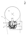
- Fig. 1 eine Reinigungsvorrichtung zum Reinigen der in ei-ner Rotationsdruckmaschine befindlichen Leitwalze, wobei bei die Reinigungsvorrichtung hier in einem Querschnitt gezeigt ist,
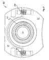
- Fig. 2 die Reinigungsvorrichtung aus Figur 1 in einem Teil-Längsschnitt, wobei die Reinigungsvorrichtung im Bereich der Wellenlagerung ihrer Reinigungsbürste dargestellt ist,
- Fig. 3 die für die Reinigungsbürste vorgesehene Wellenlagerung der Reinigungsvorrichtung aus den Fig. 1 und 2, und
- Fig. 4 die Reinigungsvorrichtung aus den Fig. 1 bis 3 im Bereich des der Reinigungsbürste einerseits und der Leitwalze andererseits zugeordneten gemeinsamen Drehantriebs.
- 1 shows a cleaning device for cleaning the guide roller located in a rotary printing machine, wherein the cleaning device is shown here in a cross section,
- 2 shows the cleaning device from FIG. 1 in a partial longitudinal section, wherein the cleaning device is shown in the area of the shaft bearing of its cleaning brush,
- Fig. 3 provided for the cleaning brush shaft bearing of the cleaning device of FIGS. 1 and 2, and
- Fig. 4, the cleaning device of FIGS. 1 to 3 in the region of the cleaning brush on the one hand and the guide roller on the other hand associated common rotary drive.
Die Reinigungsvorrichtung 1 weist beidseits an ihren Stirnendbereichen jeweils einen Schmutzauslaß 6 auf; über die beidseits an den Stirnendbereichen' der Reinigungsbürste 4 vorgesehenen Schmutzauslässe 6 können die mittels der Reinigungsbürste 4 gelösten Schmutzpartikel abgeführt werden. Da die Reinigungsvorrichtung 1 eine über die Längserstreckung der Reinigungsbürste 4 reichende Absaugglocke entbehrlich macht, und da die hier dargestellte Reinigungsvorrichtung 1 stattdessen an ihren Stirnendbereichen jeweils einen Schmutzauslaß 6 hat, zeichnet sich die Reinigungsvorrichtung 1 durch eine geringe Einbautiefe und somit durch einen vergleichsweise geringen Platzbedarf aus. Um die Schmutzpartikel in der Reinigungsvorrichtung 1 in Richtung zum angrenzenden Schmutzauslaß 6 transportieren zu können, hat die Reinigungsbürste 4 zwei Teilbereiche 7 und mit gegensinnig umlaufenden Borsten, die die in diesen Teilbereichen 7, 8 von der Leitwalze 2 entfernten Schmutzpartikel zum jeweils angrenzenden Schmutzauslaß 6 bewegen. Von den beidseits vorgesehenen Schmutzauslässen 6 ist in Figur 2 nur ein Schmutzauslaß 6 zu sehen. Da die gegensinnigen Teilbereiche 7, 8 der Reinigungsbürste 4 die an der Leitwalze 2 befindlichen Schmutzpartikel leicht lösen und im Inneren der Reinigungsvorrichtung 1 bis zum be-nachbarten Schmutzauslaß 6 transportieren können, zeichnet sich die Reinigungsvorrichtung 1 auch durch eine gute Reinigungswirkung aus.The cleaning device 1 has on both sides at their Stirnendbereichen in each case a
Aus einem Vergleich der Figuren 1 und 2 wird deutlich, dass die beiden Teilbereiche 7, 8 des Borstenfeldes der Reinigungsbürste 4 eine etwa gleichgroße Längserstreckung aufweisen und etwa in der Mitte des Borstenfeldes aneinander angrenzen. Die Welle 9 der Reinigungsbürste 4 ist an ihren beiden Wellenendbereichen und zusätzlich auch im Verlauf ihrer Längserstreckung vorzugsweise etwa mittig mittels einer Wellenlagerung 10 abgestützt. Dabei wird die Reinigungsbürste 4 im Bereich ihrer Wellenlagerung 10 mittels wenigstens einer Druckfeder 20 druckbeaufschlagt, welche Druckfeder 20 die Reinigungsbürste 4 gegen die zu reinigende Leitwalze 2 presst.From a comparison of Figures 1 and 2 it is clear that the two
In Fig. 3 ist die Reinigungsvorrichtung 1 im Bereich einer ihrer Wellenlagerungen 10 dargestellt. In Fig. 3 ist gut zu erkennen, dass die Reinigungsbürste 4 an ihren Bürstenendbereichen und vorzugsweise auch im Bereich des Borstenfeldes zwischen den Reinigungsbürsten-Teilbereichen 7, 8 beweglich gelagert ist. Die Reinigungsbürste ist dazu in einem Reinigungsbürsten-Lager 21 gehalten, welches mittels einer Andruckkraft gegen die Leitwalze bewegbar ist. Dabei ist als Andruckkraft zumindest eine Druckfeder 20 vorgesehen, welche sich an einer Lageraufnahme 23 abstützt und das Reinigungsbürsten-Lager 21 druckbeaufschlagt.In Fig. 3, the cleaning device 1 in the region of one of its
Die Reinigungsvorrichtung 1 weist ein Gehäuse 12 auf, das aus einem Strangpressprofil hergestellt ist. Das Gehäuse 12 hat einen Hohlraum 13, der in seinem lichten Querschnitt mit geringem Abstand an den Außenumfang der Reinigungsbürste 4 formangepaßt ist. Der Hohlraum ist längsseitig offen, wobei aus der längsseitigen Hohlraumöffnung 14 des Strangpressprofils 12 die Borsten 5 der Reinigungsbürste 4 einsatzbereit vorstehen.The cleaning device 1 has a
In Figur 2 ist angedeutet, dass die Reinigungsbürste 4 und die von ihr zu reinigende Leitwalze 2 einen gemeinsamen Drehantrieb 15 aufweisen. Dieser Drehantrieb 15 ist vorzugsweise so ausgestaltet, dass die Leitwalze 2 einerseits und die Reinigungswalze 4 andererseits gegenläufige Drehrichtungen haben.In FIG. 2, it is indicated that the cleaning
In Fig. 4 ist der gemeinsame Drehantrieb 15 näher dargestellt, welcher der Leitwalze 2 einerseits und der Reinigungswalze 4 andererseits zugeordnet ist. Dieser Drehantrieb 15 weist einen Antriebsmotor 25 auf, dessen Antriebswelle über einen durch die Antriebsräder 26, 27 angedeuteten Riemenantrieb mit der Reinigungswalze 4 verbunden ist. Diesem Riemenantrieb ist ein Riemenspanner 28 zugeordnet, der trotz der beweglichen Lagerung der Reinigungsbürste 4 für einen stets gespannten Antriebsriemen sorgt. Die gegenläufige Drehrichtung der Leitwalze 2 wird über zwei Zahnräder 29, 30 erreicht, die über einen weiteren, durch die Antriebsräder 31, 32 angedeuteten Riemenantrieb mit einem Reibrad 33 in Antriebsverbindung stehen. Dieses Reibrad 33 beaufschlagt die Walzenoberfläche der hier nicht weiter dargestellten Leitwalze 2. In Fig. 4 ist angedeutet, dass die Reinigungsvorrichtung 1 mit Hilfe zumindest eines Pneumatikzylinders 34 an die Leitwalze 2 angelegt oder von dieser auf Abstand gebracht werden kann.In Fig. 4, the
In Fig. 1 ist angedeutet, dass das Gehäuse 12 der Reinigungsvorrichtung 1 ein sich vorzugsweise über die Reinigungsbürste
4 erstreckendes Waschmittel-Sprührohr 35 aufweisen kann, das einen Sprühmittelauftrag auf die Reinigungsbürste 4 erlaubt. Im unteren Bereich des Gehäuses 12 ist ein Waschmittel-Ablauf 36 vorgesehen, in welchem das verwendete Waschmittel wieder aufgefangen und aus dem Gehäuse 12 abgeführt werden kann.In Fig. 1 it is indicated that the
4 may have extending
Die hier dargestellte Reinigungsvorrichtung 1 zeichnet sich durch ihren geringen Platzbedarf sowie durch ihre hohe Reinigungswirkung aus.The cleaning device 1 shown here is characterized by its small footprint and by its high cleaning effect.
Claims (11)
Applications Claiming Priority (1)
| Application Number | Priority Date | Filing Date | Title |
|---|---|---|---|
| DE102006046071A DE102006046071B3 (en) | 2006-09-27 | 2006-09-27 | Cleaning system for rollers in rotary printing machines comprises rotary brush mounted against roller which has counter-rotating sections with bristles in spiral which pass material removed from roller to central outlet or two end outlets |
Publications (3)
| Publication Number | Publication Date |
|---|---|
| EP1908591A2 true EP1908591A2 (en) | 2008-04-09 |
| EP1908591A3 EP1908591A3 (en) | 2008-04-16 |
| EP1908591B1 EP1908591B1 (en) | 2010-08-18 |
Family
ID=38830951
Family Applications (1)
| Application Number | Title | Priority Date | Filing Date |
|---|---|---|---|
| EP07018962A Not-in-force EP1908591B1 (en) | 2006-09-27 | 2007-09-26 | Cleaning device for a rotary printing press |
Country Status (3)
| Country | Link |
|---|---|
| US (1) | US20080087182A1 (en) |
| EP (1) | EP1908591B1 (en) |
| DE (2) | DE102006046071B3 (en) |
Families Citing this family (3)
| Publication number | Priority date | Publication date | Assignee | Title |
|---|---|---|---|---|
| DE102009058744B4 (en) * | 2009-12-17 | 2012-11-29 | Technotrans Ag | Cleaning device for printing and printing plate cylinders |
| DE102014113178A1 (en) * | 2014-09-12 | 2016-03-17 | Manroland Web Systems Gmbh | Cleaning device for a printing press |
| CN116899938A (en) * | 2023-06-14 | 2023-10-20 | 安徽国风新材料股份有限公司 | A rubber roller surface cleaning device for film processing |
Citations (1)
| Publication number | Priority date | Publication date | Assignee | Title |
|---|---|---|---|---|
| DE3812678C3 (en) | 1988-04-16 | 1996-04-11 | Heidelberger Druckmasch Ag | Device for cleaning cylindrical surfaces in rotary printing machines |
Family Cites Families (10)
| Publication number | Priority date | Publication date | Assignee | Title |
|---|---|---|---|---|
| DE3120983A1 (en) * | 1980-05-28 | 1982-04-29 | Dai Nippon Insatsu K.K., Tokyo | Device for washing the blanket cylinder of a rotary offset press |
| US4875611A (en) * | 1987-12-10 | 1989-10-24 | Xerox Corporation | Roll media feed roll system |
| NO305738B1 (en) * | 1990-06-14 | 1999-07-19 | Baldwin Technology Corp | Printing device comprising rotary dryer brush member |
| US5597413A (en) * | 1992-12-07 | 1997-01-28 | Xerox Corporation | Donor brush |
| JP2592694Y2 (en) * | 1993-07-15 | 1999-03-24 | ニッカ株式会社 | Printing machine cylinder cleaning device |
| DE19860854A1 (en) * | 1998-12-31 | 2000-07-06 | Koenig & Bauer Ag | Device for cleaning a roller |
| DE10053322A1 (en) * | 2000-10-27 | 2002-05-08 | Roland Man Druckmasch | Washing device for printer inking machinery comprises a driven helical coil that rotates next to a print cylinder so that it removes excess ink by use of rubber coil on its surface, providing reliable and low-maintenance cleaning |
| US20020157205A1 (en) * | 2001-04-27 | 2002-10-31 | Akira Hara | Cylinder cleaning brush unit |
| JP2005001243A (en) * | 2003-06-12 | 2005-01-06 | Baldwin Japan Ltd | Cylinder cleaning liquid supply device, cylinder cleaning brush unit and cylinder cleaning device |
| DE10344115A1 (en) * | 2003-09-24 | 2005-04-21 | Richard Munz | Cleaning device for printing cylinder |
-
2006
- 2006-09-27 DE DE102006046071A patent/DE102006046071B3/en not_active Expired - Fee Related
-
2007
- 2007-09-21 US US11/859,183 patent/US20080087182A1/en not_active Abandoned
- 2007-09-26 EP EP07018962A patent/EP1908591B1/en not_active Not-in-force
- 2007-09-26 DE DE502007004763T patent/DE502007004763D1/en active Active
Patent Citations (1)
| Publication number | Priority date | Publication date | Assignee | Title |
|---|---|---|---|---|
| DE3812678C3 (en) | 1988-04-16 | 1996-04-11 | Heidelberger Druckmasch Ag | Device for cleaning cylindrical surfaces in rotary printing machines |
Also Published As
| Publication number | Publication date |
|---|---|
| DE502007004763D1 (en) | 2010-09-30 |
| EP1908591B1 (en) | 2010-08-18 |
| US20080087182A1 (en) | 2008-04-17 |
| DE102006046071B3 (en) | 2008-01-24 |
| EP1908591A3 (en) | 2008-04-16 |
Similar Documents
| Publication | Publication Date | Title |
|---|---|---|
| EP0963927B1 (en) | Method for cleaning conveyor-belts | |
| DE19627973A1 (en) | Cleaning device | |
| EP0693378B1 (en) | Apparatus for cleaning cylinders | |
| EP3140441B1 (en) | Device with a drafting device for cleaning roller surfaces of a drafting system device | |
| DE102010002629B4 (en) | Brush head for a cleaning device and cleaning device | |
| DE10050974A1 (en) | Scraper assembly, to clean a roller surface, has the scraper mounted to one side of the opening at a suction channel with a tangential suction connection for extraction of matter detached by the scraper | |
| EP2823746B1 (en) | Cleaning device for the wet cleaning of floor surfaces | |
| EP1908591B1 (en) | Cleaning device for a rotary printing press | |
| EP0817884B1 (en) | Cleaning device | |
| EP3310235B1 (en) | Cleaning tool having an impact on the surface to be cleaned | |
| DE60211410T2 (en) | Machine for cleaning a tarpaulin | |
| DE1427953C3 (en) | Device for cleaning the work rolls in a roll stand | |
| DE2124085A1 (en) | ||
| DE2458241A1 (en) | METHOD AND DEVICE FOR CARDING NON-WOVEN FABRICS | |
| DE10115670C1 (en) | Device for cleaning the surface (s) of a moving material web | |
| DE60114110T2 (en) | Self-cleaning paper web insertion device for a web-fed rotary printing machine | |
| DE102004062114B4 (en) | Method for cleaning a plurality of cylinders of a printing unit of a printing press | |
| EP2140066A1 (en) | Cleaning apparatus | |
| DE102016119055A1 (en) | Cleaning device for a surface of a cylinder of a printing and / or copying machine | |
| DE19860855A1 (en) | Device for cleaning a roller | |
| DE102016010377A1 (en) | Device for treating material | |
| DE19860859A1 (en) | Device for cleaning a roller | |
| EP1601533A1 (en) | Cleaning device for printing cylinders | |
| DE3838721C2 (en) | Device for applying a strip of glue | |
| CH693029A5 (en) | A device for cleaning guide rollers of a web-fed rotary printing machine. |
Legal Events
| Date | Code | Title | Description |
|---|---|---|---|
| PUAI | Public reference made under article 153(3) epc to a published international application that has entered the european phase |
Free format text: ORIGINAL CODE: 0009012 |
|
| PUAL | Search report despatched |
Free format text: ORIGINAL CODE: 0009013 |
|
| AK | Designated contracting states |
Kind code of ref document: A2 Designated state(s): AT BE BG CH CY CZ DE DK EE ES FI FR GB GR HU IE IS IT LI LT LU LV MC MT NL PL PT RO SE SI SK TR |
|
| AX | Request for extension of the european patent |
Extension state: AL BA HR MK RS |
|
| AK | Designated contracting states |
Kind code of ref document: A3 Designated state(s): AT BE BG CH CY CZ DE DK EE ES FI FR GB GR HU IE IS IT LI LT LU LV MC MT NL PL PT RO SE SI SK TR |
|
| AX | Request for extension of the european patent |
Extension state: AL BA HR MK RS |
|
| 17P | Request for examination filed |
Effective date: 20080515 |
|
| 17Q | First examination report despatched |
Effective date: 20080709 |
|
| AKX | Designation fees paid |
Designated state(s): DE FR GB IT SE |
|
| GRAP | Despatch of communication of intention to grant a patent |
Free format text: ORIGINAL CODE: EPIDOSNIGR1 |
|
| GRAS | Grant fee paid |
Free format text: ORIGINAL CODE: EPIDOSNIGR3 |
|
| GRAA | (expected) grant |
Free format text: ORIGINAL CODE: 0009210 |
|
| AK | Designated contracting states |
Kind code of ref document: B1 Designated state(s): DE FR GB IT SE |
|
| REG | Reference to a national code |
Ref country code: GB Ref legal event code: FG4D Free format text: NOT ENGLISH |
|
| REF | Corresponds to: |
Ref document number: 502007004763 Country of ref document: DE Date of ref document: 20100930 Kind code of ref document: P |
|
| REG | Reference to a national code |
Ref country code: SE Ref legal event code: TRGR |
|
| PGFP | Annual fee paid to national office [announced via postgrant information from national office to epo] |
Ref country code: DE Payment date: 20100928 Year of fee payment: 4 |
|
| PG25 | Lapsed in a contracting state [announced via postgrant information from national office to epo] |
Ref country code: IT Free format text: LAPSE BECAUSE OF FAILURE TO SUBMIT A TRANSLATION OF THE DESCRIPTION OR TO PAY THE FEE WITHIN THE PRESCRIBED TIME-LIMIT Effective date: 20100818 |
|
| PLBE | No opposition filed within time limit |
Free format text: ORIGINAL CODE: 0009261 |
|
| STAA | Information on the status of an ep patent application or granted ep patent |
Free format text: STATUS: NO OPPOSITION FILED WITHIN TIME LIMIT |
|
| 26N | No opposition filed |
Effective date: 20110519 |
|
| REG | Reference to a national code |
Ref country code: DE Ref legal event code: R097 Ref document number: 502007004763 Country of ref document: DE Effective date: 20110519 |
|
| PGFP | Annual fee paid to national office [announced via postgrant information from national office to epo] |
Ref country code: GB Payment date: 20110921 Year of fee payment: 5 Ref country code: SE Payment date: 20110920 Year of fee payment: 5 Ref country code: FR Payment date: 20110908 Year of fee payment: 5 |
|
| PG25 | Lapsed in a contracting state [announced via postgrant information from national office to epo] |
Ref country code: SE Free format text: LAPSE BECAUSE OF NON-PAYMENT OF DUE FEES Effective date: 20120927 |
|
| REG | Reference to a national code |
Ref country code: SE Ref legal event code: EUG |
|
| GBPC | Gb: european patent ceased through non-payment of renewal fee |
Effective date: 20120926 |
|
| REG | Reference to a national code |
Ref country code: FR Ref legal event code: ST Effective date: 20130531 |
|
| PG25 | Lapsed in a contracting state [announced via postgrant information from national office to epo] |
Ref country code: DE Free format text: LAPSE BECAUSE OF NON-PAYMENT OF DUE FEES Effective date: 20130403 Ref country code: GB Free format text: LAPSE BECAUSE OF NON-PAYMENT OF DUE FEES Effective date: 20120926 |
|
| PG25 | Lapsed in a contracting state [announced via postgrant information from national office to epo] |
Ref country code: FR Free format text: LAPSE BECAUSE OF NON-PAYMENT OF DUE FEES Effective date: 20121001 |
|
| REG | Reference to a national code |
Ref country code: DE Ref legal event code: R119 Ref document number: 502007004763 Country of ref document: DE Effective date: 20130403 |