EP1908590B1 - Procédé de déplacement d'objet et machine d'impression - Google Patents
Procédé de déplacement d'objet et machine d'impression Download PDFInfo
- Publication number
- EP1908590B1 EP1908590B1 EP07291126.6A EP07291126A EP1908590B1 EP 1908590 B1 EP1908590 B1 EP 1908590B1 EP 07291126 A EP07291126 A EP 07291126A EP 1908590 B1 EP1908590 B1 EP 1908590B1
- Authority
- EP
- European Patent Office
- Prior art keywords
- cap
- printing machine
- base
- support zone
- drive
- Prior art date
- Legal status (The legal status is an assumption and is not a legal conclusion. Google has not performed a legal analysis and makes no representation as to the accuracy of the status listed.)
- Not-in-force
Links
- 238000007639 printing Methods 0.000 title claims description 29
- 238000000034 method Methods 0.000 title claims description 11
- 238000012546 transfer Methods 0.000 claims description 24
- 238000013459 approach Methods 0.000 claims description 8
- 230000000295 complement effect Effects 0.000 claims description 4
- 230000002093 peripheral effect Effects 0.000 claims description 2
- 230000014759 maintenance of location Effects 0.000 claims 2
- 125000006850 spacer group Chemical group 0.000 description 6
- 238000006073 displacement reaction Methods 0.000 description 3
- 239000008188 pellet Substances 0.000 description 3
- 238000013519 translation Methods 0.000 description 3
- 238000012545 processing Methods 0.000 description 2
- 230000001419 dependent effect Effects 0.000 description 1
- 238000001035 drying Methods 0.000 description 1
- 239000000428 dust Substances 0.000 description 1
- 238000012423 maintenance Methods 0.000 description 1
- 235000020004 porter Nutrition 0.000 description 1
- 238000007650 screen-printing Methods 0.000 description 1
- 230000001360 synchronised effect Effects 0.000 description 1
Images


Classifications
-
- B—PERFORMING OPERATIONS; TRANSPORTING
- B41—PRINTING; LINING MACHINES; TYPEWRITERS; STAMPS
- B41F—PRINTING MACHINES OR PRESSES
- B41F17/00—Printing apparatus or machines of special types or for particular purposes, not otherwise provided for
- B41F17/002—Supports of workpieces in machines for printing on hollow articles
-
- B—PERFORMING OPERATIONS; TRANSPORTING
- B41—PRINTING; LINING MACHINES; TYPEWRITERS; STAMPS
- B41F—PRINTING MACHINES OR PRESSES
- B41F15/00—Screen printers
- B41F15/08—Machines
- B41F15/0872—Machines for printing on articles having essentially cylindrical surfaces
Definitions
- the invention relates to a transfer device for moving elliptical or cylindrical section objects for printing on a printing machine having a rotary plate with vertical axis of rotation.
- a transfer device comprising a lifting arm provided with gripping tongs and pivotally mounted at one of its ends about an axis of rotation extending in a horizontal plane inscribed in the plane of removal of the object.
- the arm is pivotable about the axis of rotation between a loading position in which the arm extends in a vertical direction and an unloading position in which the arm extends in a horizontal direction.
- Such a device is known to FR 2,775,471 .
- this transfer device does not allow to arrange the object to be printed in a device for retaining and rotating the object for printing, comprising a base which comprises a vertical bottom and a shape rim complementary to the shape of the base of the object.
- the object can not be introduced and positioned against the bottom of the base, so as to cooperate with the rim.
- the object of the invention is to provide a transfer device enabling the object to be printed to be placed in a device for retaining and rotating the object.
- the object of the invention is
- the printing machine and the method comprise one or more of the features set forth in the dependent claims.
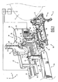
- the printing machine 2 comprises a not shown frame, a rotary plate 4 carried by the frame, at least one device 6 for retaining and driving the objects carried by the turntable 4, and processing stations for objects, not shown, arranged around the turntable 4.
- the turntable 4 is adapted to be rotated about a vertical axis of rotation by drive means 5 to move the objects to be printed from one processing station to another.
- the drive means 5 comprise a global cam indexer driven via a gear unit by an asynchronous motor or by a servomotor.
- the treatment stations include, for example, a loading station, represented on the figure 1 , and for example a flame station, one or more printing stations by screen printing or hot stamping, a drying station, a varnishing station and an unloading station identical to the loading station.
- the retaining and driving assembly 6 comprises a base 12 and a point 18 for retaining the opening 19 of the object, arranged opposite the base 12.
- the objects 8 are here bottles whose neck forms the opening 19.
- the base 12 consists of a vertical bottom 14 parallel to the plane defined by X and Z directions represented on the figure 1 , and a flange 16 delimiting a complementary shaped shape to the shape of the base 17 of the bottle 8.
- the tip 18 is displaceable in the Y direction toward and away from the base 12 in order to axially grip the bottle 8 between the base 12 and the tip 18.
- the tip 18 is mounted to be displaceable in translation on along two sliding columns 20.
- the base 12 is adapted to be driven axially in rotation by drive means 22. Unlike the tip, the base 12 is fixed in translation in the direction Y.
- the objects to be printed 8 are arranged with their axis of revolution disposed horizontally along the normal N2 to the plane of the bottom 17 of the base.
- the printing machine 2 further comprises a supply conveyor 24 of the printing bottles 8, and a transfer device 26 carried by the frame and adapted to move the bottles 8 of the supply conveyor 24 to the retaining and driving assembly 6.
- the printing machine 2 further comprises a discharge conveyor of the printed objects, not shown, and a not shown transfer device which ensures the unloading of the printed objects 8 from the retaining and driving assembly 6 towards the conveyor discharge.
- the supply conveyor 24 comprises a conveyor belt 28 closed in a loop and held between two parallel rolls of reversal, one of which is motorized. On this conveyor, the bottles 8 are arranged successively in alignment, with their axis of revolution arranged in the vertical direction Z, parallel to a normal N1 to the conveyor belt 28.
- the conveyor belt 28 constitutes a support range of the objects.
- the transfer device 26 is adapted to take a bottle whose base 17 is supported on the support pad 28, to transfer it to the retaining and driving device 6 by rotating it by a 90 ° angle around an axis parallel to the direction X, and to introduce its base 17 in the base 12.
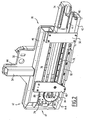
- the transfer device 26 comprises a frame 30, a gripping arm 32 carried by the frame 30, and a motor 34 for moving the driving means 36 of the gripping arm 32.
- the frame 30 comprises a support plate 38 and a plate 40 forming the base of the frame 30, the plate 40 being fixed to the support plate 38 by one of its longitudinal sides 41, so that the main face of the plate 40 is extended perpendicular to the main face of the support plate 38.
- the support plate 38 has a generally rectangular shape and has a vertical extension 44 disposed opposite the plate 40.
- the support plate 38 separates a front side 45 and a rear side 47 of the transfer device 26.
- the frame 30 further comprises a beam 46 extending in the Y direction and fixed at the edge of the rear face 47 of the support plate 38, and two spacers 48 and 50 each attached to one end of the beam 46 and to a 42 side of the tray 40 opposite its ends.
- the frame 30 further comprises a hollow holding beam 54 attached to the rear face 47 of the extension 44 and to the beam 46.
- the holding beam 54 extends in the Z direction, above the beam 46.
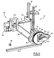
- the gripping arm 32 illustrated on the figures 4 and 5 , comprises a bracket 56, two support bars 58, 60 fixed along the longitudinal edges of the bracket 56, and two pairs 62, 64 of grip grippers slidably mounted along the support bars 58 and 60.
- the console 56 has a parallelepipedal general shape having a main face, on which the support bars 58 and 60 are fixed, and an opposite main face, on which a device 68 for actuating pairs of clamps is mounted.
- the gripping arm 32 further comprises a spacer 72 of triangular shape, one side of which is fixed to the lateral side of the bracket 56.
- the motor 34 is able to drive in translation in the Y direction a carriage 74 shown on the figures 1 , 2 and 4 .
- the drive means 36 comprise two guide rails 76,78 of the carriage 74 extending in the Y direction, a toothed wheel 80 and a rack 82 with which the gear wheel 80 is engaged.
- the guide rails 76 and 78 illustrated on the figure 2 , are fixed to the right of each other, one to the beam 46 and the other to the plate 40.
- the toothed wheel 80 has an axis of rotation A-A.
- the rack 82 is fixed to the plate 40 parallel to the rails 76 and 78.
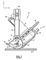
- the drive means 36 further comprise a plate 84 supporting a groove 86, and a roller 88 having a shape adapted to cooperate with the groove 86.
- the plate 84 is integral with the rear face of the toothed wheel 80.
- the groove 86 comprises a first guide portion 90 eccentric with respect to the axis of rotation A-A of the wheel 80, and a second guide portion 92 close to the axis of rotation of the wheel 80.
- the first guide portion 90 has a profile obtained by purity so that the gripping arm 32 has an arcuate trajectory tangent to the normal N2 to the bottom plane 14 of the base.
- the second portion 92 has a profile corresponding to a cycloidal movement.
- the second groove portion 92 has a length of 1/3 to 1/2 of the total length of the groove 86.
- the roller 88 illustrated on Figures 5 to 9 , is fixed on the front face of the spacer 48 facing the rear face of the gear wheel 80.
- the rack 82 extends over a length equal to the perimeter of the gear wheel 80 at which the length of the second portion 92 of the groove is subtracted.
- the drive means 36 further comprise a shaft 94, one end of which is fixed to the center of the toothed wheel 80 parallel to the axis of rotation A-A, and a rotatable support 96 integral with the other end of the shaft 94.
- the shaft 94 is able to be rotated by the carriage 74 during the displacement thereof along the guide rails 76 and 78.
- the carriage 74 comprises a bearing 97 traversed by the shaft 94.
- the rotatable support 96 extends in a plane parallel to the plane of the toothed wheel 80. It is adapted to pivot about the axis of rotation A-A of the toothed wheel 80.
- the drive means 36 finally comprise a connecting rod 98, one end 100 of which is connected to a front face 104 of the rotary support 96, a slide 104 linked to the other end 106 of the connecting rod and a slide 110 for guiding the slide 104 .
- the slide 110 is fixed to the front face 45 of the support plate 38. It extends over the extension 44 in the Z direction.
- the slide 110 extends over a length substantially equal to the diameter of the toothed wheel 80, plus the length of the connecting rod 98.
- the end 100 of the connecting rod is fixed to the rotary support 96 at a distance from the axis of rotation A-A equal to the pitch radius of the toothed wheel 80.
- the connecting rod 98 is fixed over part of its length to one side of the spacer 72 of the gripper arm 32 to drive it in motion.
- the rod 98 has a length equal to the perimeter of the toothed wheel 80, plus the length of the first groove portion 90, divided by 2 .
- a set of power and control wiring with a general J shape ( figure 3 ) is fixed to the front face 45 of the support plate 38.
- Dust protection curtains 114 are mounted in longitudinal rails on the front face 45 of the frame.
- the printing machine 2 further comprises a control unit 115 able to control the drive means 5 of the turntable and the drive motor 34 of the gripping arm 32.
- the control unit 115 is able to temporally manage the displacement of the turntable 4 and the actuation of the motor 34 so that the movement of the gripping arm 32 is synchronized with the rotational movement of the turntable 4.
- control unit 115 is able to control the motor 34 and the drive means 5 so that the gripping arm 32 arrives at the end of the removal stroke of the object on the retaining device. drive 6, when the holding and driving device 6 is located at the right of the support surface 28.
- the control unit is also able to control the actuating device 68 of the grippers 62, 64 to control the opening and closing of each pair of grippers 62, 64 each time the gripper arm 32 is in position. end-of-stroke for gripping the object disposed on the support surface and releasing the object in the holding and driving device 6.
- the turntable 4 is adapted to pivot about its axis of rotation to dispose the device of retaining and driving 6 carried by it facing the supply conveyor 24.
- the conveyor belt 28 moves to bring the bottle 8 to the end of the supply conveyor 24.
- the drive means of the transfer device are represented on the figure 6 .
- the carriage 74, the toothed wheel 80 and the first end 100 of the connecting rod are disposed at one end of the frame 30 adjacent to the spacer 50 and the motor 34.
- the other end 106 of the connecting rod is in a low position close to the
- the support bars 58, 60 of the grip grippers 62, 64 are disposed vertically close to the bottle 8.
- the actuating device 68 is implemented so that the pairs of clamps 62, 64 enclose the bottle 8.
- the drive carriage 74 is moved to the other end of the frame 30 in the direction of the spacer 48.
- the gear wheel 80 is rotated counterclockwise on the rack 82, so that that the end 100 of the rod is rotated about the axis AA.
- the slide 104 moves on the slide 110 in the Z direction.
- the end 100 of the rod is driven in a cycloidal motion.
- the end 106 of the rod is driven in displacement in a vertical translational movement.
- the gripping arm 32 is moved in a complex movement resulting from the combination of movements of the ends 100 and 106 of the rod made simultaneously.
- the bottle 8 is first raised to disengage the conveyor 24, then the bottle is rotated to bring its axis of revolution in the horizontal direction Y.
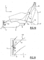
- the neck 19 is raised to move the bottle 8 away from the support pad 28 at the beginning of the trajectory 116 of the neck 19. Simultaneously, the base 17 of the bottle pivots from the beginning of the trajectory 118 of the base 17.
- the trajectory 116 of the neck 19 of the bottle and the trajectory 118 of its base 17 intersect as visible on the figures 1 and 10 .
- the base 17 passes before the neck 19 by the cross point 119.
- the roller 88 enters the second portion 92 of the groove 86 at the axis of rotation AA and is guided by the groove 86.
- the slide 104 moves on the slide 110 in the direction opposite to the Z direction.
- end 100 is displaced in a movement imposed by the second portion 92 of the groove, which has a profile corresponding to the cycloidal movement imposed during the transfer step by the toothed wheel 80 and the rack 82.
- the end 100 of the rod is moved according to a movement imposed by the first portion 90 of the groove.
- the toothed wheel 80 is no longer carried by the rack 82.
- the slide 104 moves on the slideway 110 in the direction opposite to the Z direction.
- the movement of the end 100 of the connecting rod is deflected to force the arm gripping 32 trajectories 116,118 to introduce the base 17 of the bottle in the base.
- the trajectory of the base 17 of the object has a curved portion having a point of inflection 120 in its portion 121 approaching the base 12, and comprises both a component according to the normal N1 to the range of support 28 and a component according to the normal N2 at the bottom 14 of the base.
- the trajectory 118 of the base 17 has an arcuate portion 122 tangent to the normal N2, to introduce the base 17 in the base.
- the rotary plate of the printing machine can be positioned at the same height as the conveyor belt of the conveyor or at any other height chosen, regardless of the length of the object to be printed.
- the transfer device comprises a tilting lifting arm, whose length is a function of the length of the object to be printed.
- the rotating plate carrying the devices for retaining and driving objects is positioned at a distance of high height, which requires a high weight frame and makes maintenance operations difficult on the printing stations arranged above the turntable.
Landscapes
- Engineering & Computer Science (AREA)
- Mechanical Engineering (AREA)
- Specific Conveyance Elements (AREA)
- Feeding Of Articles By Means Other Than Belts Or Rollers (AREA)
Priority Applications (1)
| Application Number | Priority Date | Filing Date | Title |
|---|---|---|---|
| PL07291126T PL1908590T3 (pl) | 2006-09-26 | 2007-09-21 | Sposób przemieszczania przedmiotu i maszyna do drukowania |
Applications Claiming Priority (1)
| Application Number | Priority Date | Filing Date | Title |
|---|---|---|---|
| FR0608431A FR2906179B1 (fr) | 2006-09-26 | 2006-09-26 | Dispositif de transfert et machine d'impression. |
Publications (3)
| Publication Number | Publication Date |
|---|---|
| EP1908590A2 EP1908590A2 (fr) | 2008-04-09 |
| EP1908590A3 EP1908590A3 (fr) | 2008-05-28 |
| EP1908590B1 true EP1908590B1 (fr) | 2013-07-03 |
Family
ID=38353917
Family Applications (1)
| Application Number | Title | Priority Date | Filing Date |
|---|---|---|---|
| EP07291126.6A Not-in-force EP1908590B1 (fr) | 2006-09-26 | 2007-09-21 | Procédé de déplacement d'objet et machine d'impression |
Country Status (7)
| Country | Link |
|---|---|
| US (1) | US7845273B2 (pl) |
| EP (1) | EP1908590B1 (pl) |
| BR (1) | BRPI0704905A (pl) |
| ES (1) | ES2427569T3 (pl) |
| FR (1) | FR2906179B1 (pl) |
| PL (1) | PL1908590T3 (pl) |
| RU (1) | RU2440896C2 (pl) |
Cited By (1)
| Publication number | Priority date | Publication date | Assignee | Title |
|---|---|---|---|---|
| CN109720868A (zh) * | 2019-02-26 | 2019-05-07 | 广州市鑫徕升机械设备有限公司 | 一种全自动特种丝网印刷机械 |
Families Citing this family (8)
| Publication number | Priority date | Publication date | Assignee | Title |
|---|---|---|---|---|
| FR2943634B1 (fr) * | 2009-03-24 | 2011-04-22 | Cer | Machine et procede de marquage ou d'etiquetage |
| FR3001648B1 (fr) * | 2013-02-04 | 2015-07-17 | Illinois Tool Works | Machine et procede de marquage d'articles |
| CN107867047A (zh) * | 2017-11-29 | 2018-04-03 | 深圳市天慧谷科技股份公司 | 全自动丝网印刷机 |
| CN109131993B (zh) * | 2018-10-26 | 2024-06-07 | 赵欣欣 | 药瓶运输中转装置及其自动化生产设备 |
| CN109532215B (zh) * | 2018-12-20 | 2021-07-13 | 许振松 | 一种多功能丝网印刷机 |
| CN109466929B (zh) * | 2018-12-30 | 2023-12-26 | 无锡华氏恒辉精密装备科技有限公司 | 一种aoi检测下料装置 |
| CN112319020A (zh) * | 2020-08-25 | 2021-02-05 | 云月(广州)科技有限公司 | 一种全自动智能丝印机 |
| CN113306280B (zh) * | 2021-04-15 | 2023-01-10 | 青岛海佰利机械有限公司 | 全自动印刷工艺 |
Family Cites Families (5)
| Publication number | Priority date | Publication date | Assignee | Title |
|---|---|---|---|---|
| US5249663A (en) * | 1991-10-04 | 1993-10-05 | Carl Strutz And Company, Inc. | Apparatus to load workpieces |
| US5333720A (en) * | 1992-05-14 | 1994-08-02 | Carl Strutz & Co., Inc. | Apparatus to manipulate workpieces |
| DE4431596C1 (de) * | 1994-09-05 | 1995-10-19 | Balsfulland Maschfabrik Gmbh | Vorrichtung zum Bedrucken der Oberfläche von Gegenständen |
| US6223882B1 (en) * | 1998-02-27 | 2001-05-01 | Societe D'exploitation Des Machines Dubuit | Loading and/or offloading device, in particular for printing machines |
| FR2775471B1 (fr) * | 1998-02-27 | 2000-05-19 | Dubuit Mach | Dispositif de chargement et/ou de dechargement a organe de transfert a basculer, en particulier pour machine a imprimer |
-
2006
- 2006-09-26 FR FR0608431A patent/FR2906179B1/fr not_active Expired - Fee Related
-
2007
- 2007-09-21 PL PL07291126T patent/PL1908590T3/pl unknown
- 2007-09-21 ES ES07291126T patent/ES2427569T3/es active Active
- 2007-09-21 EP EP07291126.6A patent/EP1908590B1/fr not_active Not-in-force
- 2007-09-25 BR BRPI0704905-6A patent/BRPI0704905A/pt not_active Application Discontinuation
- 2007-09-25 RU RU2007135623/11A patent/RU2440896C2/ru not_active IP Right Cessation
- 2007-09-26 US US11/902,835 patent/US7845273B2/en not_active Expired - Fee Related
Cited By (1)
| Publication number | Priority date | Publication date | Assignee | Title |
|---|---|---|---|---|
| CN109720868A (zh) * | 2019-02-26 | 2019-05-07 | 广州市鑫徕升机械设备有限公司 | 一种全自动特种丝网印刷机械 |
Also Published As
| Publication number | Publication date |
|---|---|
| US20080245244A1 (en) | 2008-10-09 |
| RU2007135623A (ru) | 2009-03-27 |
| RU2440896C2 (ru) | 2012-01-27 |
| EP1908590A3 (fr) | 2008-05-28 |
| US7845273B2 (en) | 2010-12-07 |
| FR2906179B1 (fr) | 2009-06-05 |
| BRPI0704905A (pt) | 2008-05-13 |
| ES2427569T3 (es) | 2013-10-31 |
| FR2906179A1 (fr) | 2008-03-28 |
| PL1908590T3 (pl) | 2013-11-29 |
| EP1908590A2 (fr) | 2008-04-09 |
Similar Documents
| Publication | Publication Date | Title |
|---|---|---|
| EP1908590B1 (fr) | Procédé de déplacement d'objet et machine d'impression | |
| EP0069661B1 (fr) | Plieuse automatique de tôles | |
| CA2004409C (fr) | Machine, notamment encartonneuse, pour mettre automatiquement un article, en particulier un flacon, dans un etui | |
| FR2652529A1 (fr) | Robot. | |
| FR2683515A1 (fr) | Appareil pour saisir et transporter des piles d'objets plats. | |
| FR2675482A1 (fr) | Dispositif de manutention destine au convoyage de panneaux, notamment des panneaux lateraux constituant la carrosserie d'un vehicule. | |
| EP1518675B1 (fr) | Machines à imprimer | |
| EP0445044B1 (fr) | Machine à cintrer les tubes à deux têtes de cintrage | |
| EP0286514B1 (fr) | Convoyeur à plaques permettant notamment le transport de récipients | |
| EP2051918B1 (fr) | Dispositif de retournement de récipients | |
| EP0320376B1 (fr) | Installation pour la mise en place de manchons d'étiquetage sur des objets tels que des bidons | |
| EP1775126B1 (fr) | Dispositif de transfert d'un objet pour machine d'impression, machine d'impression et procédé de transfert | |
| FR2463003A1 (fr) | Perfectionnements aux machines de serigraphie concernant la monture porte-objets et son mouvement relatif par rapport a l'ecran | |
| FR2573006A1 (fr) | Machine a imprimer | |
| FR2489802A1 (fr) | Perfectionnements a une machine rinceuse automatique, notamment pour bouteilles | |
| FR2602119A1 (fr) | Machine automatique pour le chargement et le dechargement des plateaux des cadres a rayons dans le traitement des viandes en general | |
| EP0390658A1 (fr) | Dispositif pour transporter des pièces vers un ou plusieurs postes de traitement, et les en évacuer | |
| FR2525147A1 (fr) | Appareil pour charger et pour decharger des presses industrielles | |
| FR2505238A1 (fr) | Moyen de transfert de pieces du type robot a double bras | |
| EP0114774B1 (fr) | Chargeur-extracteur de pièces à un seul moteur de commande | |
| EP0220967A1 (fr) | Convoyeur de récipients | |
| FR2668976A1 (fr) | Dispositif pour amener et aligner des feuilles de papier sur une table de marge de machines d'impression. | |
| EP1543965A1 (fr) | Machine d'impression par sérigraphie avec dispositif de transfert d'objets à imprimer | |
| FR2795012A1 (fr) | Dispositif de transfert de pieces a usiner | |
| FR2819483A1 (fr) | Dispositif de presentation d'opercules a des postes de scellage mobiles |
Legal Events
| Date | Code | Title | Description |
|---|---|---|---|
| PUAI | Public reference made under article 153(3) epc to a published international application that has entered the european phase |
Free format text: ORIGINAL CODE: 0009012 |
|
| AK | Designated contracting states |
Kind code of ref document: A2 Designated state(s): AT BE BG CH CY CZ DE DK EE ES FI FR GB GR HU IE IS IT LI LT LU LV MC MT NL PL PT RO SE SI SK TR |
|
| AX | Request for extension of the european patent |
Extension state: AL BA HR MK RS |
|
| PUAL | Search report despatched |
Free format text: ORIGINAL CODE: 0009013 |
|
| AK | Designated contracting states |
Kind code of ref document: A3 Designated state(s): AT BE BG CH CY CZ DE DK EE ES FI FR GB GR HU IE IS IT LI LT LU LV MC MT NL PL PT RO SE SI SK TR |
|
| AX | Request for extension of the european patent |
Extension state: AL BA HR MK RS |
|
| 17P | Request for examination filed |
Effective date: 20081105 |
|
| AKX | Designation fees paid |
Designated state(s): DE ES GB IT PL |
|
| 17Q | First examination report despatched |
Effective date: 20090113 |
|
| REG | Reference to a national code |
Ref country code: DE Ref legal event code: R079 Ref document number: 602007031370 Country of ref document: DE Free format text: PREVIOUS MAIN CLASS: B41F0017000000 Ipc: B41F0015080000 |
|
| GRAP | Despatch of communication of intention to grant a patent |
Free format text: ORIGINAL CODE: EPIDOSNIGR1 |
|
| RIC1 | Information provided on ipc code assigned before grant |
Ipc: B41F 17/00 20060101ALI20120906BHEP Ipc: B41F 15/08 20060101AFI20120906BHEP Ipc: B65G 47/90 20060101ALI20120906BHEP Ipc: B65G 47/91 20060101ALI20120906BHEP |
|
| GRAP | Despatch of communication of intention to grant a patent |
Free format text: ORIGINAL CODE: EPIDOSNIGR1 |
|
| GRAS | Grant fee paid |
Free format text: ORIGINAL CODE: EPIDOSNIGR3 |
|
| GRAA | (expected) grant |
Free format text: ORIGINAL CODE: 0009210 |
|
| AK | Designated contracting states |
Kind code of ref document: B1 Designated state(s): DE ES GB IT PL |
|
| REG | Reference to a national code |
Ref country code: GB Ref legal event code: FG4D Free format text: NOT ENGLISH |
|
| REG | Reference to a national code |
Ref country code: DE Ref legal event code: R096 Ref document number: 602007031370 Country of ref document: DE Effective date: 20130829 |
|
| REG | Reference to a national code |
Ref country code: ES Ref legal event code: FG2A Ref document number: 2427569 Country of ref document: ES Kind code of ref document: T3 Effective date: 20131031 |
|
| REG | Reference to a national code |
Ref country code: PL Ref legal event code: T3 |
|
| PLBE | No opposition filed within time limit |
Free format text: ORIGINAL CODE: 0009261 |
|
| STAA | Information on the status of an ep patent application or granted ep patent |
Free format text: STATUS: NO OPPOSITION FILED WITHIN TIME LIMIT |
|
| 26N | No opposition filed |
Effective date: 20140404 |
|
| REG | Reference to a national code |
Ref country code: DE Ref legal event code: R097 Ref document number: 602007031370 Country of ref document: DE Effective date: 20140404 |
|
| PGFP | Annual fee paid to national office [announced via postgrant information from national office to epo] |
Ref country code: ES Payment date: 20150928 Year of fee payment: 9 |
|
| PGFP | Annual fee paid to national office [announced via postgrant information from national office to epo] |
Ref country code: CH Payment date: 20170828 Year of fee payment: 11 Ref country code: GB Payment date: 20170914 Year of fee payment: 11 |
|
| PG25 | Lapsed in a contracting state [announced via postgrant information from national office to epo] |
Ref country code: ES Free format text: LAPSE BECAUSE OF NON-PAYMENT OF DUE FEES Effective date: 20160922 |
|
| PGFP | Annual fee paid to national office [announced via postgrant information from national office to epo] |
Ref country code: IT Payment date: 20180911 Year of fee payment: 12 |
|
| REG | Reference to a national code |
Ref country code: ES Ref legal event code: FD2A Effective date: 20181126 |
|
| PGFP | Annual fee paid to national office [announced via postgrant information from national office to epo] |
Ref country code: PL Payment date: 20180817 Year of fee payment: 12 |
|
| REG | Reference to a national code |
Ref country code: DE Ref legal event code: R119 Ref document number: 602007031370 Country of ref document: DE |
|
| GBPC | Gb: european patent ceased through non-payment of renewal fee |
Effective date: 20180921 |
|
| PG25 | Lapsed in a contracting state [announced via postgrant information from national office to epo] |
Ref country code: DE Free format text: LAPSE BECAUSE OF NON-PAYMENT OF DUE FEES Effective date: 20190402 |
|
| PG25 | Lapsed in a contracting state [announced via postgrant information from national office to epo] |
Ref country code: GB Free format text: LAPSE BECAUSE OF NON-PAYMENT OF DUE FEES Effective date: 20180921 |
|
| PG25 | Lapsed in a contracting state [announced via postgrant information from national office to epo] |
Ref country code: IT Free format text: LAPSE BECAUSE OF NON-PAYMENT OF DUE FEES Effective date: 20190921 |
|
| PG25 | Lapsed in a contracting state [announced via postgrant information from national office to epo] |
Ref country code: PL Free format text: LAPSE BECAUSE OF NON-PAYMENT OF DUE FEES Effective date: 20190921 |