EP1908423B1 - Endoskopischer chirurgischer Klammerapplikator - Google Patents
Endoskopischer chirurgischer Klammerapplikator Download PDFInfo
- Publication number
- EP1908423B1 EP1908423B1 EP07253807A EP07253807A EP1908423B1 EP 1908423 B1 EP1908423 B1 EP 1908423B1 EP 07253807 A EP07253807 A EP 07253807A EP 07253807 A EP07253807 A EP 07253807A EP 1908423 B1 EP1908423 B1 EP 1908423B1
- Authority
- EP
- European Patent Office
- Prior art keywords
- clip
- actuator
- bar
- pawl
- lockout
- Prior art date
- Legal status (The legal status is an assumption and is not a legal conclusion. Google has not performed a legal analysis and makes no representation as to the accuracy of the status listed.)
- Not-in-force
Links
Images


Classifications
-
- A—HUMAN NECESSITIES
- A61—MEDICAL OR VETERINARY SCIENCE; HYGIENE
- A61B—DIAGNOSIS; SURGERY; IDENTIFICATION
- A61B17/00—Surgical instruments, devices or methods
- A61B17/12—Surgical instruments, devices or methods for ligaturing or otherwise compressing tubular parts of the body, e.g. blood vessels or umbilical cord
- A61B17/128—Surgical instruments, devices or methods for ligaturing or otherwise compressing tubular parts of the body, e.g. blood vessels or umbilical cord for applying or removing clamps or clips
- A61B17/1285—Surgical instruments, devices or methods for ligaturing or otherwise compressing tubular parts of the body, e.g. blood vessels or umbilical cord for applying or removing clamps or clips for minimally invasive surgery
-
- A—HUMAN NECESSITIES
- A61—MEDICAL OR VETERINARY SCIENCE; HYGIENE
- A61B—DIAGNOSIS; SURGERY; IDENTIFICATION
- A61B17/00—Surgical instruments, devices or methods
- A61B2017/00367—Details of actuation of instruments, e.g. relations between pushing buttons, or the like, and activation of the tool, working tip, or the like
- A61B2017/00407—Ratchet means
-
- A—HUMAN NECESSITIES
- A61—MEDICAL OR VETERINARY SCIENCE; HYGIENE
- A61B—DIAGNOSIS; SURGERY; IDENTIFICATION
- A61B90/00—Instruments, implements or accessories specially adapted for surgery or diagnosis and not covered by any of the groups A61B1/00 - A61B50/00, e.g. for luxation treatment or for protecting wound edges
- A61B90/03—Automatic limiting or abutting means, e.g. for safety
- A61B2090/037—Automatic limiting or abutting means, e.g. for safety with a frangible part, e.g. by reduced diameter
-
- A—HUMAN NECESSITIES
- A61—MEDICAL OR VETERINARY SCIENCE; HYGIENE
- A61B—DIAGNOSIS; SURGERY; IDENTIFICATION
- A61B90/00—Instruments, implements or accessories specially adapted for surgery or diagnosis and not covered by any of the groups A61B1/00 - A61B50/00, e.g. for luxation treatment or for protecting wound edges
- A61B90/08—Accessories or related features not otherwise provided for
- A61B2090/0803—Counting the number of times an instrument is used
Definitions
- the present disclosure relates to a surgical clip applier according to claim 1. More particularly, the present disclosure relates to a surgical clip applier having a mechanism for stabilizing a jaw structure of the surgical clip applier and also having a mechanism to prevent firing the surgical clip applier when the surgical clip applier has exhausted the amount of stored clips to prevent a dry firing of the surgical clip applier.
- Laparoscopic procedures are performed in the interior of the abdomen. The procedures are through a small incision and through a narrow endoscopic tube or cannula inserted through a small entrance incision in the skin. Minimally invasive procedures performed elsewhere in the body are often generally referred to as "endoscopic" procedures. The surgeon will insert and extend a tube or cannula device in the body through the entrance incision to provide an access port. This port allows insertion of various surgical instruments therethrough.
- One advantage of minimally invasive surgical procedures is the reduction of trauma to the patient as a result of accessing internal organs through smaller incisions.
- Known endoscopic clip appliers have greatly facilitated the advent of more advanced minimally invasive procedures by permitting a number of clip applications during a single entry into the body cavity.
- Commercially available endoscopic clip appliers are generally of 10 mm outer diameter and are adapted to be introduced through a 10 mm cannula.
- Other commercially available endoscopic clip appliers may also be generally of 5 mm outer diameter and are adapted to be introduced through a 5 mm cannula.
- WO 2006/042076 relates to an endoscopic surgical clip applier
- the applier comprises a wedge plate configured to maintain the jaw assembly in the spaced apart position during loading of the surgical clip. It also reduces torque and external forces on the jaw assembly during loading.
- EP 1317906 discloses a surgical clip applier.
- the applier comprises a lockout mechanism for rendering the clip applier inoperable upon deforming a last clip of the series of clips, the lockout mechanism including a first blocking member for engagement with a cam plate to prevent movement of the cam plate, and at least one frangible member to disengage the cam plate from the handles upon closure of the handles when first blocking member is engaged with the cam plate.
- the structure of surgical instruments intended to perform numerous functions within a confined space is necessarily complex.
- the assembly process for these instruments is often complicated and may involve numerous relatively small parts to perform the numerous functions with repeatability. It is therefore desirable to maximize the ease with which such instruments may be assembled.
- the present invention provides an apparatus (1010) for application of surgical clips to body tissue, which comprises:
- a surgical clip applying apparatus with a handle portion, a body extending distally from the handle portion defining a longitudinal axis and a number of surgical clips disposed within the body.
- the apparatus has a movable member biased in the housing adjacent the wedge plate.
- An actuator longitudinally advances the wedge plate a predetermined distance to a distal most position.
- the wedge plate has an end being disposed between first and second jaw portions at the distal most position. The wedge plate end is configured to maintain the jaw assembly in the spaced apart position during loading of the surgical clip and the wedge plate end reduces torque on the jaw assembly during the loading.
- the movable member holds the wedge plate in the distal most position during the loading and the movable member is deflected at a conclusion of the loading.
- the movable member releases the wedge plate upon deflection and the rotatable member allowing a longitudinal proximal retraction of the wedge plate from the distal most position.
- an apparatus for application of surgical clips to body tissue has a handle assembly with a handle and a trigger movable relative to the handle.
- the trigger has a trigger lockout notch.
- the apparatus also has a body extending distally from the handle portion and defining a longitudinal axis and a plurality of surgical clips disposed within the body and a jaw assembly mounted adjacent a distal end portion of the body with the jaw assembly including first and second jaw portions movable between a spaced apart and an approximated position.
- the apparatus also has a clip pusher configured to individually distally advance a surgical clip to the jaw assembly while the jaw portions are in the spaced apart position.
- the apparatus also further has an actuator at least partially disposed within the body and longitudinally movable in response to actuation of the handle portion.
- the apparatus further has a lockout mechanism with a first rotatable member with a first shaft and a first arm having a first pawl.
- the first shaft fixedly engages the handle portion and the mechanism has a second rotatable member with an escape notch on a radial position of the second rotatable member with a second post, and a plurality of teeth disposed around substantially an inner circumference of an inner surface of the second rotatable member.
- the mechanism has a third rotatable member with an aperture for receiving the second post and the third rotatable member is configured to engage with the trigger.
- the pawl rotates in the inner surface of the second rotatable member to mesh with the teeth and the pawl advances to a next tooth of the plurality of teeth when the trigger is fired.
- the teeth are complementary in number to the remaining clips and when the clips are exhausted the pawl is advanced to the escape notch. If the trigger is fired and the clips are exhausted, the first pawl traverses out from the second rotatable member to the trigger notch. The pawl mates with the trigger notch to prevent firing.
- an apparatus for application of surgical clips to body tissue comprising a handle portion and a body extending distally from the handle portion and defining a longitudinal axis.
- the apparatus also has a plurality of surgical clips disposed within the body and a jaw assembly mounted adjacent a distal end portion of the body.
- the jaw assembly further comprises first and second jaw portions movable between a spaced apart and an approximated position.
- the apparatus has a wedge plate longitudinally movable between the first and the second jaw portions and a clip pusher configured to individually distally advance a surgical clip to the jaw assembly while the jaw portions are in the spaced apart position.
- the apparatus also has an actuator at least partially disposed within the body and longitudinally movable in response to actuation of the handle portion, and a jaw closure member positioned adjacent the first and the second jaw portions to move the jaw portions to the approximated position.
- the actuator longitudinally advances the wedge plate a predetermined distance to a distal most position.
- the wedge plate has an end being disposed between the first and the second jaw portions at the distal most position.
- the wedge plate end is configured to maintain the jaw assembly in the spaced apart position during loading of the surgical clip.
- the end reduces torque on the jaw assembly during the loading and the actuator further actuates a signal device.
- the signal device indicates that at least one of the clips has fired.
- an apparatus for application of surgical clips to body tissue has a handle portion, and a body extending distally from the handle portion and defining a longitudinal axis.
- the apparatus has surgical clips disposed within the body and a jaw assembly mounted adjacent a distal end portion of the body with the jaw assembly further comprising first and second jaw portions movable between a spaced apart and an approximated position.
- the apparatus has a wedge plate longitudinally movable between the first and the second jaw portions and a clip pusher configured to individually distally advance a surgical clip to the jaw assembly while the jaw portions are in the spaced apart position.
- the apparatus also has an actuator at least partially disposed within the body and longitudinally movable in response to actuation of the handle portion.
- the apparatus further has a jaw closure member positioned adjacent the first and the second jaw portions to move the jaw portions to the approximated position.
- the actuator longitudinally advances the wedge plate a predetermined distance to a distal most position and the wedge plate has an end being disposed between the first and the second jaw portions at the distal most position.
- the wedge plate end is configured to maintain the jaw assembly in the spaced apart position during loading of the surgical clip. The end reduces torque on the jaw assembly during loading.
- the actuator further actuates an audible device configured to indicate that at least one of the clips has fired.
- an apparatus for application of surgical clips to body tissue has a handle portion, a body extending distally from the handle portion and defining a longitudinal axis, and a plurality of surgical clips disposed within the body.
- the apparatus also has a jaw assembly mounted adjacent a distal end portion of the body with the jaw assembly further comprising first and second jaw portions movable between a spaced-apart and an approximated position.
- the apparatus also has a wedge plate longitudinally movable between the first and the second jaw portions, and a clip pusher configured to individually distally advance a surgical clip to the jaw assembly while the jaw portions are in the spaced apart position.
- the apparatus also has an actuator at least partially disposed within the body and longitudinally movable in response to actuation of the handle portion, and a jaw closure member positioned adjacent the first and the second jaw portions to move the jaw portions to the approximated position.
- the actuator longitudinally advances the wedge plate a predetermined distance to a distal most position, and the wedge plate has an end being disposed between the first and the second jaw portions at the distal most position.
- the wedge plate end is configured to maintain the jaw assembly in the spaced apart position during loading of the surgical clip.
- the wedge plate end reduces torque on the jaw assembly during loading.
- the apparatus further has the body connected to the handle by a rotatable member.
- the rotatable member is fixedly connected to the handle and the body.
- the rotatable member is a plurality of members having a first elongated knob housing and a second knob with a plurality of notches being disposed therearound.
- the second knob is disposed over the knob housing. At least one of the members is adapted to be rotated by an index finger for rotating the body.
- an apparatus for application of surgical clips to body tissue has a handle portion and a body extending distally from the handle portion and defining a longitudinal axis.
- the apparatus also has a plurality of surgical clips disposed within the body and a jaw assembly mounted adjacent a distal end portion of the body.
- the jaw assembly includes first and second jaw portions movable between a spaced apart and an approximated position.
- the apparatus also has a feed bar configured to individually distally advance a surgical clip to the jaw assembly while the jaw portions are in the spaced apart position.
- the apparatus further has a clip pusher disposed proximal to the plurality of clips and configured to bias the plurality of clips in a distal manner with an actuator at least partially disposed within the body and longitudinally movable in response to actuation of the handle portion.
- the apparatus also has a jaw closure member positioned adjacent the first and second jaw portions to move the jaw portions to the approximated position and a rack having a plurality of ratchet teeth being connected to the actuator.
- a pawl with at least one tooth is configured to engage the ratchet teeth.
- the pawl is biased in the handle portion.
- the pawl is configured to prevent an inadvertent return of the actuator before full actuation of the apparatus.
- the apparatus also has a bar being disposed in proximity to the feed bar.
- the bar is biased by a spring and lodged between a ceiling and a floor of the clip carrying channel.
- the clip carrying channel includes a distal window. As the clip pusher moves distally each time a clip is released from the apparatus the clip pusher moves the bar distally. When the bar is in substantial alignment with the distal window, the bar moves through the distal window to deflect the feed bar to a second position.
- the feed bar in the second position prevents the actuator from moving proximally and thereby manipulates the pawl to be engaged with the ratchet teeth of the rack.
- the pawl and rack prevent the actuator from longitudinally moving.
- An apparatus for application of surgical clips to body tissue includes a handle portion and a body extending distally from the handle portion and defining a longitudinal axis.
- the apparatus also has a plurality of surgical clips disposed within the body and a jaw assembly mounted adjacent a distal end portion of the body.
- the jaw assembly includes first and second jaw portions movable between a spaced apart and an approximated position.
- the apparatus also includes a feed bar configured to individually distally advance a surgical clip to the jaw assembly while the jaw portions are in the spaced apart position.
- the feed bar includes at least one proximal fin.
- the apparatus also has a clip pusher disposed proximal to the plurality of clips and configured to bias the plurality of clips in a distal manner.
- the apparatus also has an actuator at least partially disposed within the body and longitudinally movable in response to actuation of the handle portion.
- the actuator includes a proximal window.
- a jaw closure member is positioned adjacent the first and second jaw portions to move the jaw portions to the approximated position.
- a rack having a plurality of ratchet teeth is connected to the actuator.
- the apparatus also includes a pawl having at least one tooth configured to engage the ratchet teeth with the pawl biased in the handle portion.
- the apparatus also has a bar disposed in proximity to the feed bar. The bar is biased by a spring and lodged between a ceiling and a floor of a clip carrying channel.
- the clip carrying channel includes a distal window. As the clip pusher moves distally each time a clip is released from the apparatus, the clip pusher moves the bar distally. When the bar is in substantial alignment with the distal window, the bar that is biased by the spring moves through the distal window to deflect the feed bar to a second position.
- the feed bar in the second position includes the proximal fin in engagement with the proximal window of the actuator.
- the engagement of the feed bar and the actuator prevents retraction but not advancement of the actuator and thereby manipulates the pawl to be engaged with the rack in a substantially intermediate position.
- the pawl and rack prevent the actuator from moving longitudinally to thereby lock the actuator.
- An apparatus for application of surgical clips to body tissue includes a clip pusher that incrementally moves distally each time a clip is released from the apparatus.
- the feed bar is deflected to a second position.
- the feed bar in the second position has a portion that is in engagement with the actuator.
- the feed bar in the second deflected position prevents retraction but not advancement of the actuator and thereby manipulates the pawl to be engaged with ratchet teeth of the rack.
- the pawl and rack prevent the actuator from moving longitudinally to thereby lock the actuator.
- a novel endoscopic surgical clip applier having a jaw control mechanism configured to maintain jaws of the surgical clip applier in a spaced apart and stable position during insertion of a surgical clip.
- the novel endoscopic surgical clip applier also has a lockout mechanism.
- the lockout mechanism prevents the surgical clip applier from firing when there are no remaining hemostatic clips.
- the novel endoscopic surgical clip applier also has a signaling device for alerting the surgeon that a clip has been fired. It should be noted that, while the disclosed jaw control mechanism, the driver lockout and the signaling device are all shown and described in an endoscopic surgical clip applier, the disclosed mechanisms are applicable to any surgical clip applier or another instrument having a pair of compressible jaws.
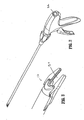
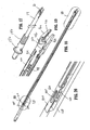
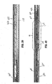
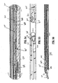
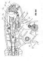
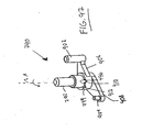
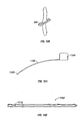
- the surgical clip applier 10 generally has a handle assembly 12 and an endoscopic portion with an elongated tubular member 14 that extends distally from the handle assembly 12.
- the handle assembly 12 is made from a thermoplastic material and the elongated member is made from a biocompatible material.
- the material may be a stainless steel or in yet another embodiment a titanium material or alloy.
- a pair of jaws 16 is mounted on the distal end of the tubular member 14.
- the jaws 16 are actuated by a trigger 18.
- the trigger is movably mounted in handle assembly 12.
- the jaws 16 are also formed from a suitable biocompatible material such as stainless steel, titanium or a suitable alloy.
- the endoscopic portion also has a knob 20.
- the knob 20 is rotatably mounted on a distal end of the handle assembly 12 and is connected to the elongated tubular member 14 to provide a three hundred sixty degree rotation of the elongated tubular member 14 and the jaws 16 thereon relative to a longitudinal center axis of the elongated tubular member 14.
- a significant aspect of the clip applier 10 is that the knob 20 has a suitable configuration so as to be rotated simply using a surgeon's finger, and will be discussed in depth below.
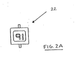
- the endoscopic surgical clip applier 10 has a display 22.
- the display 22 may be any device known in the art to provide an indication of an event.
- the event may be related to the procedure or the operation of the clip applier 10.
- the display 22 in a preferred embodiment may be a liquid crystal display.
- the display 22 may be a plasma display, one or more light emitting diodes, a luminescent display, a multi-color display, a digital display, an analog display, a passive display, an active display, a so called “twisted nematic” display, a so called “super twisted nematic” display, a “dual scan” display, a reflective display, a backlit display, an alpha numeric display, a monochrome display, a so called “Low Temperature Polysilicon Thin Film Transistor" or LPTS TFT display, or any other display 22 that indicates a parameter, information or graphics related to the procedure or the clip applier 10.
- the display is a liquid crystal display 22 or "LCD”.
- the LCD 22 may be a black and white or color display that displays one or more operating parameters of the clip applier 10 to the surgeon.
- Fig. 2A there is shown a front view of the LCD display 22.
- the display 22 shows a displayed parameter.
- the displayed parameter may be an amount of remaining clips, a number clips that have been used, a position parameter, a surgery time of usage, or any other parameter of the procedure.
- the LCD 22 may display text, a graphic or a combination thereof.
- the LCD 22 may have a tab made from a Mylar or another polymeric insulating material that is disposed between a LCD 22 battery and a contact of the LCD 22 to prevent the battery from being drained during storage.
- the tab may extend out of the clip applier 10 in order to allow for removal of the tab. Once removed, the tab will be pulled out from the clip applier 10 and will permit the battery to contact the electrical contact of the LCD 22 to energize the LCD 22 with power.
- the LCD 22 has a lens that magnifies the display. The lens of the LCD 22 may magnify the display to any desired size in order to allow a surgeon to read the display with ease from a distance.
- the jaws 16 have a channel 24 for receipt of a single surgical clip therein. As is known, a surgical clip may be applied or placed in the channel 24 by a loading structure of the clip applier 10 to apply the hemostatic clip in, for example, a body cavity.
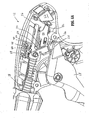
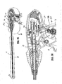
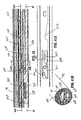
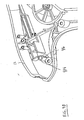
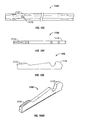
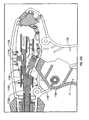
- the handle assembly 12 of the endoscopic surgical clip applier 10 is shown from a first open lateral side of the handle assembly 12.
- the endoscopic surgical clip applier 10 has the trigger 18 connected to a wishbone link 26.
- the wishbone link 26 is a member that on one end is connected to the trigger 18 through a trigger slot 28 and on an opposite end has first and a second wishbone shaped members 30, 32.
- the first and a second wishbone shaped members 30, 32 form a space 34 for receipt of a driving member 36.
- the driving member 36 is a substantially flat member that is longitudinally disposed in the handle assembly 12 as shown and is intended to move one or more driving structures to load, and actuate the jaws 16 to form a fully formed clip, and then reset to an initial position for the next clip application.
- a return spring 38 is disposed to surround the driving member 36.
- the driving member 36 is connected to a driving mechanism to fire the clip applier 10 and is suitably connected such that after the trigger 18 is actuated and the wishbone link 26 advances the driving member 36 in a longitudinal or distal manner, the return spring 38 will return the driving member 36 and the trigger 18 to its original position for the next clip application.
- the driving member 36 is advantageous.
- the driving member 36 prevents an inadvertent return of the trigger 18 before a full actuation of the open clip applier 10 by impeding movement at an intermediate position once the driving member 36 begins to advance distally.
- the driving member 36 has a rack 40.
- the rack 40 is disposed on a top side 42 thereof.
- the rack 40 has a number of teeth 44 and the teeth 44 are engaged to engage with another complementary surface to prevent inadvertent return of the trigger 18 and the driving member 18 before a full actuation of the surgical clip applier 10.
- the surgical clip applier 10 has a pawl 46 with a pawl return spring 48.
- the pawl 46 is biased with the pawl spring 48 to engage with the teeth 44 of the rack 40.
- the teeth 44 and the pawl 46 prevent a release of the trigger 18 before a full actuation of the trigger 18 as described herein below.
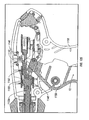
- the clip applier 10 further has an actuator plate 50.
- the actuator plate 50 is longitudinally disposed in the handle assembly 12.
- the actuator plate 50 is disposed below the driving member 36 and is operatively connected to a LCD lever 52.
- the LCD lever 52 is a suitable structure to be operatively connected to the LCD display 22.
- Lever 52 moves a suitable mechanism or contact in the LCD display 22 to permit the LCD display 22 to be actuated and thus display one or more operating parameters of the clip applier 10.
- the actuator plate 50 is connected to the LCD lever 52 to move the corresponding LCD display 22 structure or contact to display an amount of remaining clips that the surgeon has to fire.
- the display may be a number of light emitting diodes, a liquid plasma display, an electronic device or display, a changeable display or a combination thereof.
- the actuator plate 50 further has a signaling device 54.
- the signaling device 54 is a device that is connected to the actuator plate 50 and that can provide the user with an audible signal that the open clip applier 10 has fired the surgical clip.
- the signaling device 54 emits a sound once the clip applier 10 is fired to provide audible feed back to the surgeon.
- the signaling device 54 may be another electronic device that emits a characteristic sound.
- the signaling device 54 may emit a sound in response to a deflection of the handle or trigger, a compression of a clip, a loading of the clip, a loading of a new clip, an exhaustion of all of the clips, or may emit several different sounds depending on the clip applier 10 event.
- the characteristic sound may be a click, a chirp, a sound, a voice, a recording, a combination of sounds, or any acoustic wave at any decibel level.
- the signaling device 54 may further provide an identification in response to an event of the clip applier 10. In one embodiment, the signaling device 54 may emit a sound during normal operation, and then upon the occurrence of the event terminate emitting the sound.
- Various configurations are possible and all within the scope of the present disclosure.
- the clip applier 10 further has a lockout mechanism 56.
- the lockout mechanism 56 is a structure to prevent the surgeon from dry firing the open clip applier 10 when the amount of clips stored in the clip applier 10 have been exhausted.
- the lockout mechanism 56 engages a complementary structure in the trigger handle A to prevent the trigger 18 from further moving and actuating the wishbone link 26 in a manner described in more detail below.
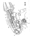
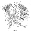
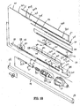
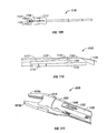
- the surgical clip applier 10 has the actuator plate 50 that is a substantially "S" shaped member. As best shown in Fig. 7 and 9A , the actuator plate 50 has a first portion 58 having a first orthogonal shaped window 60 and a second portion 62 with a second orthogonal shaped window 64.
- the actuator plate 50 On a first end of the actuator plate 50, the actuator plate 50 has a rounded off or curved portion that forms a pair of tines 66.
- the opposite second end 68 has a protrusion 70.
- the protrusion 70 engages a channel 72 on the LCD lever 52.
- a pin 74 is disposed through the first orthogonal shaped window 60 to connect the actuator plate 50 to the driving member 36 through the wishbone link 26. In this manner, when the trigger 18 moves the driving member 36 distally, the connecting pin 74 upon being moved through the first window 60 will also move the actuator plate 50 distally in a similar fashion once the connecting pin 74 contacts an outer distal edge 76 of the first orthogonal shaped window 60.
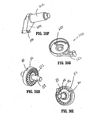
- the clip applier 10 further has the signaling device 54 with an audible click lever 78.
- the audible click lever 78 is on an opposite side of the actuator plate 50 and is through the second window 64.
- the signaling device 54 also has an audible click spring 80.
- the signaling device 54 also has the audible click lever 78 that will rotate and deflect on a complementary handle surface upon longitudinal distal movement by the actuator plate 50.
- the actuator plate 50 will move the second window 64 having a lateral side 82 (shown in Fig. 9A ) that will cause a post 77 of the audible click lever 78 ( Fig. 9B ) to deflect and cause the lever 78 to contact a surface rib on the housing. This contact produces an audible alert or an audible signal to the surgeon that the clip applier 10 has fired a surgical clip.
- the clip applier 10 further has the LCD lever 52 (best shown in Fig. 9C ) that is a rotatable member with a first lever portion 84, an aperture 86 and a curved member 88 having the channel 72.
- the channel 72 communicates with the protrusion 70 on the actuator plate 50 and has a peg 92 that communicates with the first handle housing portion 94 shown in Fig. 7 .
- the LCD 22 has a LCD unit 96 with an LCD lens 98 and a LCD counter contact plate 100 that is connected to the LCD 22.
- the LCD counter contact plate 100 upon being actuated will toggle the LCD display 22 from a previous parameter to the current parameter, such as in one embodiment, an amount of remaining clips in the clip applier 10.
- the clip applier 10 also has the pawl 46 with the pawl spring 48.
- the pawl 46 has an end that engages with the teeth 44 of the rack 40.
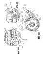
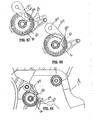
- the clip applier 10 further has the lockout mechanism 56 having a first rotatable member or shaft 102 with an arm 104 and a pawl 106 connected to the arm 104.
- the first rotatable member 102 is generally cylindrical shaped and is connected to a complementary surface of the handle through a spring 105.
- the first rotatable member 102 is a lock out arm
- the lockout mechanism 56 further has a second rotatable member 112 offset from the first rotatable member 102.
- the second rotatable member 112 in one embodiment is a lockout wheel and has a generally circular configuration with an inner circumference 114 of the lockout wheel 112 having a number of teeth 116 spaced therearound.
- the lockout wheel 112 has a centermost post 118 that is connected through an aperture to a third rotatable member 120 having a first arm 122 connected thereto, and the post 118 is further connected to the handle portion 12. As the trigger 18 is fired, there exists a relative movement between the first rotatable member 102 connected to the handle portion 12 and the third rotatable member 120 connected to the trigger 18.
- the lockout wheel 112 is intended to rotate a predetermined amount as the centermost post 118 is connected to the handle portion 12. As the lockout wheel 112 rotates, the pawl 106 of the first rotatable member 102 will advance. Each time the trigger 18 is fired to fire a clip; the pawl 106 will traverse one unit of length between the number of teeth 116 and will rest therein due to an advantageous ratcheting arrangement discussed herein.
- the lockout wheel 112 has an escape notch 110 that is an orthogonally shaped notch 110 on a radial portion thereof.
- Escape notch 110 permits the pawl 106 of the first rotatable member 102 to traverse from an inner location or the inner circumference 114 of the lockout wheel 112 outward through the escape notch 110 to engage the complementary structure in the trigger shown by reference letter A to prevent the trigger 18 from further moving and actuating the wishbone link 26.
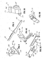
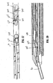
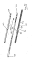
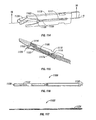
- the clip applier further has the knob 20 having a shaft assembly 124.
- a spindle link 126 connects to a spindle 128 shown in Fig. 7A .
- the driver bar 36 connects with the spindle link 126.
- the spindle link 126 on a proximal side opposite the jaws 16 has spindle link hook 185.
- the driver bar 36 has an angled hook member 186.
- the angled hook member 186 is on a distal side 184 of the driver bar 36.
- the angled hook member 186 of the driver bar 36 mates with the spindle link hook 185.
- the driving member 36 can thus advance the spindle link 126 in a distal manner.
- an opposite distal end of the spindle link 126 (relative to the spindle link hook 185) is connected with a circular boss connection 188 to the spindle 128.
- the spindle 128 may rotate independently of the spindle link 126 as shown by the reference arrow B.
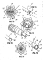
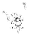
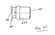
- FIG. 7B there is shown a cross sectional view of the knob 20 along line 7B-7B of Fig.5 .
- the knob 20 has a first body half 130 and a second body half 132 connected to one another in an aperture or bore 134 of the knob 20.
- the knob 20 connects with a knob housing 136 having a planar tapered surface 138 that connects with the knob 20.
- the knob 20 has the bore 134 disposed therethrough.
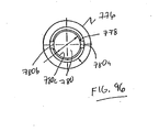
- the knob housing 136 further has an outer tubular member 142 with a first slot 144 and a second slot 146 disposed through the tubular member 142 with the outer tubular member 142 having a "C" shaped first aperture 148 and a second "C” aperture 150 on respective opposite laterals sides thereof.
- the knob housing 136 is very advantageous as the knob housing 136 has an elongated cylindrical geometry that is suitable to allow a surgeon to rotate the tubular member 14 simply with one hand by using an index finger to contact a lateral side of the knob 20 and rotate the knob 20 either in a clockwise or a counter clockwise manner. This obviates any two handed operation to rotate the tubular member 14 that is disfavored by some surgeons and provides for a more ergonomic operation or rotation of the tubular member 14.
- the knob 20 on an inner surface of the bore 134 has a first arm 152 and a second arm 154 that extend opposite an outer surface into the bore 134 for respectively mating with the first "C" shaped aperture 148 and the second "C” shaped aperture 150 of the knob housing 136.
- the outer tube 14 further has a bushing 156 with a first aperture 158' and a second aperture 160' with a first pin 162 extending through the first aperture 158' and a second pin 164 extending through the second aperture 160'.
- the bushing 156 further has a tab 166 that extends from a radial position of the bushing 156. The tab 166 engages with a notch in the knob housing 136.
- the bushing 156 also has a second tab 166'.
- the second tab 166' also engages a notch 168 in the tubular member 14 shown in Fig. 7D for rotation thereof.
- the spindle 128 is mounted for longitudinal movement through the tubular member 14.
- the pawl 46 is a triangular shaped member with an aperture 169 disposed therethrough.
- the pawl 46 also has a number of angled surfaces 170, 172, 174 on a top side 176 and a tooth engaging structure 178 on an opposite bottom side 180 for engaging with the teeth 44 on the rack 40 as shown in the driving member 36 of Fig. 6D .
- the driving member 36 has an aperture 182 for mating with the wishbone link 26 of Fig. 9D and has a first side 181 and an opposite second side 184 with an angled hook member 186 for advancement of the spindle 128 in a distal manner.
- the wishbone link 26 is connected to the driving member 36 through the first longitudinal shaped window 60 of Fig. 9A on the actuator plate 50 by means of the pin 74.
- the actuator plate 50 with the protrusion 70 connects with the channel 72 in the LCD lever 52 of Fig. 9C and the actuator plate 50 is further connected to the signaling device 54 shown in Fig. 9B .
- the signaling device 54 has an aperture 188 for mating with the handle housing.
- the audible click lever 78 has a bulbous end 190 with a resilient surface 191 such that upon rotation of the click lever 78 the bulbous end 191 can sharply contact another handle surface or rib in order to an acoustic wave to emanate from the handle assembly 12 to signal that the surgical clip has fired.
- the signaling device 54 further has the post 77 is connected through the second window 64 of Fig. 9A and that rotates the lever 54 when the actuator plate 50 moves distally.
- the clip applier 10 has the outer tubular member 14.
- the outer tubular member 14 is generally a cylindrical member having a first end 192 and a second end 194.
- the first end 192 is connected through the bore to the spindle link 126.
- the spindle link 126 is connected to the spindle 128.
- the outer tube 14 is disposed around the spindle 128.
- the clip applier 10 has pins 162, 164.
- the pins 162 and 164 extend through the lateral sides of the bushing 156.
- the pins 162, 164 are biased inward relative to the bushing 156 and contact the outer tubular member 14.
- the clip applier 10 further has a spring 196 to prevent the bushing 156 from advancing.
- the spring 196 is disposed in the knob housing 136 that connected to the knob 20.
- the clip applier 10 further has the interlocking spindle link 126 that is disposed through the bore of the elongated tubular member 14.
- the present clip applier has a number of different assemblies in order to perform a number of different clip applier functions.
- the clip applier 10 has a spindle mechanism 128 in order to traverse through the tubular member 14 to actuate a driving mechanism to close the jaws 16 and form a fully formed clip.
- the clip applier 10 also has a mechanism for a wedging function that is provided to maintain the jaws 16 in a spaced apart condition for loading the jaws 16 that retracts once the jaws 16 are loaded.
- the clip applier 10 also has a feeder function that feeds clips to the jaws 16.
- the clip applier also has a clip storage function and a clip follower function that biases the stored clips for subsequent loading thereof.
- an actuation mechanism or the spindle 128 shown above the knob 20 in Fig. 10 is provided.
- the spindle 128 is mounted for longitudinal distal and proximal movement through the elongated tubular member 14.
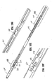
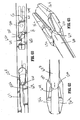
- the spindle 128 has, on a distal end 204, a camming mechanism with a driver bar 200 and a slider joint 202 that extends from a distal end 204 of the spindle 128 to selectively engage the camming surfaces and to close the jaws 16 around the surgical clip.
- the spindle 128 further has a latch member 206 on the slider joint 202 and a cam link 208 on the spindle 128.
- the latch member 206 cams in a direction toward the spindle 128.
- the latch member 20 cams into a corresponding slot of the spindle 128.
- the latch member 206 permits the driver bar 200 to move distally.
- the latch member 206 also prevents the driver bar 200 from actuating the jaws 16 when spindle 128 moves distally to reduce a predetermined dwell distance between the spindle 128 and the driver bar 200.
- the spindle 128 also has a camming feature 210 or bulging edge to move another structure in a perpendicular manner relatively to a longitudinal axis of the spindle 128 during a distal advancement.
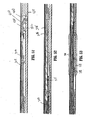
- the clip applier 10 retains one or a number of surgical clips 300 for application to the desired tissue.
- the clip applier 10 has an elongated clip channel member 302 for retaining a number of surgical clips 300 shown in an aligned manner above the clip channel member 302.
- the elongated clip channel member 302 does not move longitudinally relative to the elongated tubular member 14.
- the clip applier 10 has a follower 306 connected to a follower spring 308.
- the follower spring 308 urges clips distally in the clip channel member 302.
- the clip applier 10 also has a channel cover 310 that overlies the clip channel member 302 to retain and guide the follower 306 and the follower spring 308 and the clips 300 distally in the clip channel member 302.
- the clip applier 10 also has a nose 312 to direct the clips 300 traversing through the clip channel member 302 into the channel 24 between the jaws 16.
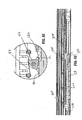
- the clip applier 10 also has a feed bar 400 for feeding clips 300 into the channel 24 between the jaws 16.
- the feed bar 400 also provides for a relative movement. Referring now to a distal portion of clip channel member 302, there is shown the feed bar 400.
- the feed bar 400 at this distal location advances the clips 300 into the channel 24 and between the jaws 16.
- the feed bar 400 has a pusher spring 402 ( Fig. 10 ).
- the pusher spring 402 biases the feed bar 400 in a longitudinal distal direction.
- the pusher spring 402 is disposed in a complementary location under a notch 404 in a trip block 406.
- the trip block 406 On a distal side of the trip block 406, the trip block 406 is adjacent to the clip channel cover member 304.
- the feed bar 400 is shown above the trip block 406.
- the feed bar 400 has a hook 408.
- the hook 408 engages in the notch 404 of the trip block 406.
- the clip applier 10 further has a guide pin 401.
- the guide pin 401 is disposed through the pusher spring 402 and necessary to align the pusher spring 402.
- the hook 408 engages with the guide pin 401 and the pusher spring 402 under the trip block 406. In this manner, the hook 408 is disposed through the notch 404 to engage the guide pin 401.
- the pusher spring 402 and guide pin 401 biases the feed bar 400 and permits the feed bar 400 to advance distally.
- the guide pin 401 being disposed through the pusher spring 402 allows for a self contained assembly.
- the spindle 128 has a trip lever 500 and a biasing spring 502.
- the trip lever 500 is engaged with the feed bar 400 to advance the surgical clips 300 distally into the clip channel 24 between the jaws 16.
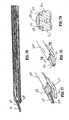
- the clip applier 100 also has a wedge plate 600 with a wedge plate spring 602.
- the wedge plate 600 is a flat bar shaped member having a number of orthogonally shaped windows 604 disposed therethrough.
- the wedge plate spring 602 surrounds a tongue 606 in the wedge plate 600 that is in a latch aperture 608.
- the wedge plate spring 602 permits the wedge plate 600 to be retracted from a distal location to a proximal location after being advanced distally to separate the jaws 16 for clip loading.
- the wedge plate 600 also has a "C" shaped window 610 that is between the windows 604 and the tongue 606.
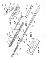
- the clip applier 10 also has a filler component 700.
- the filler component 700 has a rotatable member 702 and a spring bar member 704.
- the spring bar member 704 is in an aperture 706 disposed in the filler component 700.
- the rotatable member 702 is capable of a certain particular range of motion and has a first proximal end 708 and a second opposite distal end 710 that is opposite the first end 708.
- the range of motion of the rotatable member 702 may be any relatively slight or any relatively large range of rotation or movement.
- the present clip applier10 is not limited in any manner to any specific degree of rotation or any specific manner of movement such as circular, elliptical or even any geometric rotational pattern, origin, axis, coordinates or movement.
- the member 702 may alternatively simply move in any planar or in another irregular manner known in the art.
- Various configurations are possible and within the scope of the present disclosure.
- the clip applier 10 further has the jaws 16.
- the jaws 16 are made of a first jaw member 16a and a second jaw member 16b. Between the first jaw member 16a and the second jaw member 16b is the clip channel 24. As is understood, the jaw members 16a and 16b can move inwardly to close and compress to form a fully formed clip in the channel 24.
- the jaws 16 also have a first raised camming surface 212 and a second raised camming surface 214 on an outer surface thereof. The first raised camming surface 212 and the second raised camming surface 214 permit another driving camming surface selectively engagement therewith for closing and compressing the jaws 16.
- the feed bar 400 is a longitudinal member having the rectangular shaped window 410 for engagement with the trip lever 500.
- the feed bar 400 also has the hook 408 disposed on a bottom side 412 of the feed bar.
- the feed bar 400 further has a pusher 414 on a distal end for engaging and manipulating the surgical clips 300 in the clip carrying channel 302.
- the feed bar 400 cooperates with the follower 306 that slides in the clip carrying channel 302 for pushing and urging the clips 300 distally in the clip carrying channel 302.
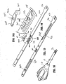
- the trip block 406 there is shown the trip block 406 both in a first position and in an opposite second position.
- the trip block 406 has the notch 404 therein and also has an angled surface forming a first and second toothed member 420.
- Each of the first and the second toothed members 420 is for engagement with the corresponding surface of the trip lever 500 that will be discussed herein.
- the notch 404 of the trip block 406 in Figs. 10C and 10D is for receipt of the hook 408 of the feed bar 400 shown in Fig. 10A .
- the trip block 406 of Fig. 10C and 10D has the first and second toothed member 420 that engage the trip lever 500 shown in Fig. 10 .
- First and second toothed member 420 disengages the trip lever 500 from the window 410 of Fig. 10A .
- the spindle 128 has a first orthogonal cavity 222 and a second orthogonal shaped cavity 224 for receiving the trip lever 500, and for receiving the trip lever biasing spring 502.
- the first orthogonal cavity 222 has a pivoting boss 226 ( Fig. 10F ) to allow the trip lever 500 to pivot from a first position to a second rotatable position.
- the trip lever biasing spring 502 rests in the second cavity 224.
- the spring 502 shown in Fig. 10 rests therein without any boss or member to connect the biasing spring 502 for ease of manufacture.
- the spindle 128 further has a groove 209 with the camming feature 210 and another cavity 228 to allow the cam link 208 to rest therein and be urged distally.
- the spindle 128 advances distally to engage the drive components of the clip applier 10 as discussed in further detail below.
- the trip lever biasing spring 502 has a first and second bowed ends 504, 506 that interlock with the second cavity 224 of the spindle 128 as indicated by a dotted line.
- the trip lever biasing spring 502 further has a second member 508.
- the second member 508 biases outward opposite a normal surface of the spindle 128.
- the second member 508 contacts the trip lever 500.
- the trip lever 500 has a C shaped end 510 that engages for rotational movement with the pivoting boss 226 of the spindle 128 and another end 512 that extends above the trip lever biasing spring 502.
- the trip block 406 has an angled surface or toothed surfaces 420 that can selectively engage the trip lever 500 and disengage the trip lever 500 from the window 410 of the feed bar 400 as discussed previously.
- the spindle 128 has the cam link 208 that is engageable with the wedge plate 600.
- the cam link 208 has a cam link boss 230 extending therefrom. The cam link 208 is urged distally by the spindle 128 during the stroke.
- the slider joint 202 is connected at a proximal end 248 to the spindle 128 at a channel 250.
- the slider joint 202 has a "T" shaped end 252.
- T shaped end 252 is connected to the driver bar 200.
- the slider joint 202 has a latch member 206 that is a linkage that is disposed to move through an aperture 254 in the slider joint 202 to link with another member and prevent the slider joint 202 from advancing the driver bar 200, and thus preventing camming surfaces 256 of the driver bar 200 from compressing the jaws 16 during the initial stroke of feeding a clip 300 into the jaws 16.
- the wedge plate 600 is shown.
- the wedge plate 600 has the wedge plate spring 602.
- the wedge plate spring 602 provides for a biasing apparatus of the wedge plate 600.
- the wedge plate 600 is biased by the wedge plate spring 602.
- the spring 602 surrounds the tongue 606 as indicated by the dotted line.
- the wedge plate 600 also has a "C" shaped aperture or window 610 therethrough.
- the "C" shaped aperture or window 610 selectively engages the rotatable member 702 of the filler component 700.
- the wedge plate 600 also has a cam slot or groove 612 having a cam surface 614.
- the cam slot or groove 612 has a predetermined shape that control a motion of the wedge plate 600.
- the cam slot or groove 612 cooperates with the cam link 208 in the spindle 128 to move the wedge plate 600 distally and to separate the jaws 16 slightly for loading.
- the cam surface 614 also cooperates with the cam link 208 to move the wedge plate 600 proximally within the tubular member 14 so the jaws 16 may compress the clip 300 in the channel 24 once loaded.
- the wedge plate 600 has a rounded distal end 616 for separating the jaws 16 for loading.
- the wedge plate 600 also has a proximal window 622 to limit retraction of the wedge plate 600.
- the filler component 700 in a first position and in a second opposite position shown in Fig. 15 .
- the filler component 700 has a C shaped end 712 and a rotatable member 702 having an aperture 714 that is connected by a pin 716 in a centermost portion of the filler component 700.
- the rotatable member 702 connects with a corresponding structure in the wedge plate 600 to control a motion of the wedge plate 600.
- On an opposite side of the filler component 700 is an aperture 718.
- the rotatable member 702 has a first end 708 and an opposite second end 710. The first end 708 is biased by contact with the spring bar member 704 that allows biasing action between the spring bar member 704 and the rotatable member 702.
- the filler component 700 also has (shown in fig. 15 ) a filler component cam slot 720.
- the filler component cam slot 720 is configured to receive the boss 230 of the cam link 208.
- the filler component 700 also has a stop 722 to limit a proximal retraction of the wedge plate 600 and also has a member 724. The member 724 engages the wedge plate tongue 606 and the spring 602.
- Figs. 16 through 17 there is shown spindle 128 and the related drive components.
- the bushing 156 has the spring 196 being connected thereto as shown in Fig. 17 to allow an over stroke condition of the jaws 16.
- Spring 196 prevents excessive force from being applied to the jaws 16.
- the feed bar 400 extends in a downward manner ( Fig. 19 ) so the pusher 414 extends into the clip carrying channel 302 to engage a clip 300.
- the pusher 414 advances each of the clips 300 in the clip channel member 302 into the channel 24 between the jaws 16.
- the clip applier 10 has a "C" shaped member 416 that is around the nose 312 that acts as a tissue stop disposed therearound. As discussed above, the nose 312 assists with a single clip being introduced in the channel 24.
- the clip applier 10 also has a number of T shaped tabs 418. The tabs 418 are in order to hold the clip carrying channel 302, the channel cover 310 and the nose 312 together as an integral unit.
- the spindle 128 has the trip lever 500.
- the trip lever 500 extends through window 410 of the feed bar 400 as shown to advance the feed bar 400 distally (through the tubular member 14) and to move the pusher 414 distally to introduce the clips 300 into the channel 24 between the jaws 16.
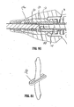
- Fig. 21 through 24 shows a number of clips 300 in a clip carrying channel 302.
- the clip carrying channel 302 has a number of fingers 420 curved therearound ( Fig. 23 ) in order to support and retain the clips 300 in the clip carrying channel 302.
- Fig. 24 there is shown a partially assembled perspective view of the follower 306.
- the follower 306 is disposed in the clip carrying channel 302 with the follower spring 308 biasing and advancing the follower 306 in a distal direction.
- the follower spring 308 imparts a force on the clips 300 in the clip channel 302.
- the clip applier 10 has a number of "T" shaped tabs 418 on the clip channel 302 in order to maintain the assembly together.
- the clip applier 10 has the trip lever 500 on the spindle 128.
- the trip lever 500 is a T shaped member that is biased to deflect opposite the spindle top side, and biased by a trip lever spring 502 as previously discussed.
- the driver bar 200 is disposed to rest on the wedge plate 600 or jaws 16 in the assembled position and will traverse distally over the first and second raised camming surfaces 212 and 214 to close the jaws 16 and compress the clip 300 in the channel 24.
- the clip applier 10 has a stop member 618 to limit movement of the filler component 700.
- the filler component 700 is disposed beneath the wedge plate 600 in this view.
- the wedge plate 600 has the "C" shaped window 610 with the rotatable member 702 disposed through the "C" shaped window 610.
- the wedge plate 600 also has the cam slot 612 having the cam surface 614.
- the cam link 208 is disposed on a top of the wedge plate 600 in this view.
- the cam link 208 has the cam link boss 230 that interfaces with the cam slot 612 of the wedge plate 600.
- the wedge plate 600 has the wedge plate spring 602 around tongue 606 and the member 724 of the filler component 700 around the tongue 606. In this manner, when the tongue 606 moves distally relative to the filler component 700 the wedge plate 600 is biased to return proximally.
- the filler component 700 also has the stop 722 in the proximal window 622 of the wedge plate 600 to further limit distal movement of the wedge plate 600 relative to the filler component 700.
- cam link 208 is also configured to be driven distally in the cam slot 612. Additionally, the cam link 208 is also configured to be ride in the filler component cam slot 720 shown beneath the wedge plate 600 in this view.
- the cam link boss 230 engages the cam surface 614 of the wedge plate 600 to drive the wedge plate 600 distally.
- the wedge plate 600 will advance distally until it reaches a demarcation line 624 shown in Fig. 30 .
- the cam link boss 231 will engage a disengaging cam surface 726 of the filler component 700 shown in Fig. 30 .
- the disengaging cam surface 726 is a feature in the filler component cam slot 720. Notably, the disengaging cam surface 726 will cam the cam link boss 231 out of engagement with cam surface 614 of cam slot 612. At this demarcation point 624, the wedge plate 600 no longer moves distally.
- the wedge plate 600 lies over the filler component 700 which is positioned on the spindle 128.
- the jaws 16 have a pair of flexible legs 17a, 17b.
- the legs 17a, 17b are fixed to a base member 17c.
- the jaws 16 are located at a distal end relative to the flexible legs 17a, 17b.
- a pair of locking arms 19a, 19b extends from the base 17c and terminates in a pair of tabs 21 a, 21 b.
- Tabs 21 a, 21 b engage a pair of holes (not shown) in the elongated outer tube 14 in order to secure the jaws 16 to the elongated tube 14.
- the filler component 700 is disposed immediately proximal relative to the jaws 16 and does not move relative to the elongated outer tube 14.
- Figs. 31 through 33 there is shown a view of the wedge component 600 disposed over the driver bar 200 and resting on the spindle 128.
- the wedge plate 600 is under the filler component 700 in Fig. 31 .
- the wedge plate 600 being best shown with the jaws removed in Fig. 33 .
- the jaws 16 are configured to receive the rounded distal end 616 of the wedge plate 600.
- the rounded distal end 616 initially separates the jaws 16.
- the rounded distal end 616 maintains the jaws 16 in a separate and aligned configuration during insertion of the clip 300 in the channel 24 of the jaws 16.
- the wedge plate 600 has the rounded distal end 616 that maintains the jaws 16 separated and notably prevents any flexing or torque of the jaws 16.
- Each of the jaws 16 has a cam feature 23a, 23b to guide the rounded distal end 616 of the wedge plate 600 between the jaws 16 as shown in Fig. 32 in an easy and repeatable manner.
- Cam feature 23a, 23b are on an inner surface of the jaws 16 as shown and is between the first raised camming surface 212 and the second raised camming surface 214.
- Fig. 34 there is shown a view of the spindle 128 having the slider joint 202 and the driver bar 200 having the wedge plate 600 removed for illustration purposes.
- the distal end of the driver bar 200 has the driver camming surface 256.
- the driver camming surface 256 cooperates and moves over the first and the second raised camming surfaces 212, 214 of the jaws 16 ( Fig. 32 ) in response to the distal movement of the driver bar 200 relative to the jaws 16.
- latch retractors 158, 160 extend perpendicular therefrom and are configured to extend through the windows 604, 604 in the wedge plate 600 shown in Fig. 33 .
- latch retractors 158, 160 limit a retraction and distal movement of the slider joint 202 relative to the jaws 16 as shown in Fig. 33 .
- latch retractor 158 retracts while latch retractor 160 limits movement.
- latch retractor 160 may retract while the latch retractor 158 limits movement.
- each latch retractor 158 and 160 can switch between functions of limiting movement and retracting.
- more than two latch retractors 158, 160 may be provided.
- Various configurations are possible and within the scope of the present disclosure.
- a target tissue such as a vessel
- the trigger 18 is shown in an uncompressed state with the driving member 36 in an original position, and biased by the spring 38.
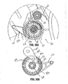
- Fig. 36A there is shown the lockout mechanism 56 of the surgical clip applier 10 with the lockout mechanism 56 in an original initial position.
- the arm 122 of the third rotatable member 120 has a portion that rests in a channel 121 of the handle assembly 12 as shown in Fig. 36A .
- the third rotatable member 120 mates with the lockout wheel 112 via post 118.
- the third rotatable member 120 is an indexer wheel.
- the inner circumference 114 of the lockout wheel 112 has a number of teeth 116 and the escape notch 110.
- the escape notch 110 is disposed at a position around the inner circumference 114.
- the first rotatable member 102 having the arm 104 and the pawl 106 is offset from the lockout wheel 112 and is disposed so that the pawl 106 selectively engages with the teeth 116 as the clip applier 10 is fired.
- the lockout wheel 112 has a predetermined number of teeth 116 complementary to the number of clips in the clip carrying channel 302 such that when the last clip is fired, the pawl 106 will be aligned with the escape notch 110 allowing the pawl 106 to enter escape notch 110 and be freed from the lockout wheel 112. Referring now to Figs.
- the lockout mechanism 56 also has a ratcheting arrangement with a ratchet arm 650 and a number of ratchet teeth 652.
- the ratchet arm 650 of the third rotatable member 120 is designed to engage with ratchet teeth 652 and rotate the lockout wheel 112 clockwise in response to actuation of the trigger 18.
- the ratchet arm 650 Upon release of the trigger 18, the ratchet arm 650 thereafter is rotated in an opposite radial direction to move over each of the ratchet teeth so as to allow the ratchet arm 650 to move counterclockwise to reset to the original position after each clip 300 is fired while not disturbing the radial advancement of the pawl 106.
- the trip lever 500 in an unfired state is carried by the spindle 128.
- the trip lever 500 is biased by the trip lever spring 502.
- the trip lever 500 also is in contact with the proximal window 410 in the feed bar 400.
- the trip block 406 is in a distal position relative to the trip lever 500.
- Fig. 39 there is shown the follower 306 biased by the follower spring 408 in order for the clips 300 to be biased in the distal direction.
- FIG. 40 there is shown another cross sectional view of the spindle 128 having the cam link 208 and the wedge plate 600 resting on the spindle 128.
- the slider joint 202 is disposed under the wedge plate 600 with the latch member 206 disposed in the slider joint 202.
- the spindle 128 drives the cam link 208 distally an initial distance such that the cam link boss 230 on the cam link 208 engages the cam slot 612 in the wedge plate 600.
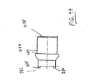
- FIG. 41 and 41 A there is shown another cross sectional view of the outer tube 14 having the filler component 700.
- the wedge plate 600 is disposed under the filler component 700 with the rotatable member 702 extending therebetween.
- the wedge plate 700 has the spring bar member 704 that is disposed in the aperture 706.
- the spring bar member 704 biases the rotatable member 702 and can deflect at its free end.
- the rotatable member 702 is disposed distal relative to the camming feature 210 of the spindle 128 that is beneath the filler component 700 shown in dotted lines. Once driven distally, the spindle 128 will advance. The spindle 128 will advance the camming feature 210.
- the camming feature 210 will be driven distally and will deflect the rotatable member 702 in a clockwise manner.
- FIG. 41 B there is shown a cross sectional view of the spindle 128 showing the various components therein along line 41 B-41 B of FIG. 41 .
- the clip 300 rests in the clip channel 302 and has the feed bar 400 on a top side thereof.
- the wedge plate 600 is disposed underneath the filler component 700 as shown and above the spindle 128.
- the clip channel cover 310 is disposed above the clip channel 302.
- the pusher 414 advances each of the clips 300 into the clip channel 24 as shown in Fig. 42A .
- the spindle 128 is disposed to connect to the slider joint 202.
- latch member 206 is mechanically forced to cam down and engages channel 250 of the spindle 128 (which is best shown in Fig. 11 ) in the direction of reference arrow L shown in Fig. 73 .
- This allows the slider joint 202 to move with the driver bar 200 (when driven) distally.
- the driver bar 200 thus can engage the relevant surfaces to close the jaws 16 around the clip 300 disposed in the channel 24 between the jaws 16.
- Fig. 43 there is shown a perspective view of the wedge plate 600 and the jaws 16 in an original proximal most position.
- the wedge plate 600 has the wedge plate spring 602 in the window 604 around the tongue 606.
- the wedge plate 600 further has a "C" shaped window 610 to engage the rotatable member 702.
- the cam link 208 is in a proximal-most position relative to the cam slot 612.
- the wedge plate 600 also has the rounded distal end 616 engageable with the cam features 23a, and 23b to separate the first jaw 16a and the second jaw 16b slightly as shown later for loading.
- the cam link 208 is initially disposed in the cam slot 612 in the initial proximal position with the filler component 700 disposed below the cam link 208 in this view.
- the rotatable member 702 has the second end 710 extending through the "C" shaped window 610.
- the first end 708 of the rotatable member 702 contacts the spring bar member 704 on the filler component 700 that is beneath the wedge plate 600.
- the trigger 18 is moved through an initial swing as shown by arrow C such that the wishbone link 26 drives the driving member as shown by arrow D.
- the rack 40 on the driving member 36 begins to slide under the pawl 46 as shown by reference arrow E and the pawl 46 rotates to deflect pawl return spring 48 by reference arrow F.
- the signaling device 54 also has an internal rib 2 that is integral with the handle assembly 12.
- the click lever 78 contacts the click lever spring 80 and upon being recoiled from the spring 80, the click lever 78 will have the bulbous portion 190 of the click lever 78 contact the internal rib 2.
- the bulbous portion 190 and the internal rib 2 will resonate thereby providing the surgeon with the audible indication of clip firing.
- the driving member 36 and the rack 40 advance distally the pawl 46 rotates as shown in Fig. 50 . If the trigger 18 were released at this point, the rack 40 would restrain the pawl 46 against any proximal motion and thus prevent release of the trigger and any partial or inadvertent partial actuation of the trigger 18.
- the lockout wheel 112 of the lockout device 56 also rotates and has the pawl 106 contacting the teeth 116 on the inner circumference 114 of the lockout wheel 112. As shown, the pawl 106 will advance from a first tooth space 3 to a next tooth space 5 once clip 300 is fired. If another clip 300 is fired, the pawl 106 will rotate from space 5 to space 7 and continue to advance in a counterclockwise manner until the pawl 106 reaches the escape notch 110 once the last clip 300 has been fired.
- the surgical clip applier 10 is loaded with a number of clips 300 that always exceeds a number of teeth of the lockout wheel 112 to ensure that the surgical clip applier 10 will never dry fire or in other words cannot fire without a clip 300.
- the spindle 128 moves a predetermined distance.
- the trip lever 500 that this biased by the trip lever spring 502 moves distally and the feed bar 400 is driven distally by the trip lever 500 engaging the feed bar window 410.
- the follower 306 as a distal most clip 300 is moved into the channel 24 of the jaws 16 by pusher 414, the follower 306 then moves in a distal direction and is urged forward by the follower spring 308. The follower 306 moves each of the clips 300 in a distal manner to be loaded individually into the channel 24 of jaws 16.
- Figs. 53 through 55 there is shown a cross sectional view of the various components of the clip applier 10 during the initial stroke with the filler component 700, wedge plate 600, and the cam link 208.
- the boss 230 on the cam link 208 contacts the cam surface 614 on the cam slot 612 of the wedge plate 600 as shown in Fig. 55 .
- the cam link 208 moves distally with the spindle 128 and the cam surface 614 is also urged distally relative to the filler component 700.
- the pusher 414 urges and advances an individual clip 300 into the channel 24 of the jaws 16 while at an opposite end, the spindle 128 has a suitable geometry such that the spindle 128 has not contacted the driver bar 200 in order to actuate and close the jaws 16.
- the cam link 208 engages the cam surface 614 of the cam slot 612 to move the wedge plate 600 distally relative to the filler component 700.
- the "C" shaped window 610 also advances distally, and a lateral surface 625 contacts the second end 710 of the rotatable member 702.
- the lateral surface 625 of the wedge plate urges the rotatable member 702 to rotate counterclockwise as shown.
- the first end 708 of the rotatable member 702 upon rotation contacts the spring bar member 704 on the filler component 700 and causes the spring bar member 704 of the filler component 700 to deflect.
- the feed bar 400 continues to urge the pusher 414 with the sloping surface to contact a single clip 300.
- the pusher 414 continues to introduce the clip 300 into the clip channel 24.
- the wedge plate 600 continues to advance and be driven distally by the cam link 208 urging the cam surface 614 of the cam slot 612 as shown by the reference arrow.
- Fig. 60 shows that the spring bar member 704 after being deflected by the rotatable member 702 recoils in a direction of reference arrow G.
- the recoil moves the rotatable member 702 clockwise so the second end 710 contacts a lateral side 626 of the "C" shaped window 610 as shown by reference arrow H.
- the rotatable member 702 thus conveniently holds the wedge plate 600 in a most distal position and completely controls a position of the wedge plate 600 for loading.
- the cam link 208 at this most distal position of Fig. 60 contacts the camming feature or the disengaging cam surface 726 of the filler component cam slot 720 on the filler component 700.
- the cam link 208 is now cammed out of engagement with the cam surface 614 and the wedge plate 600 is at its most distal position, and the cam link 208 no longer drives the wedge plate 600 distally.
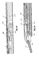
- the rounded distal end 616 of the wedge plate 600 is now moved in between the camming surface 23a, 23b of the first and the second jaw components 16a, 16b as shown.
- the rounded distal edge 616 of the wedge plate 600 thus moves the first and second jaw components 16a, 16b opposite from one another as shown for gently increasing a size of the channel 24. This additionally restrains each of the jaw members 16a, 16b from flexing with regard to one another preventing any torque on the clip 300 as it is being inserted between the jaws 16 as shown by the reference arrows.
- the cam link 208 continued to advance distally in the cam slot 612 while the wedge plate 600 is held by the rotatable member 702 at the second end 710.
- Rotatable member 702 is held by the spring bar member 704 at the second end 710 between the spring bar member 704 and a lateral wall of the aperture 706 of the filler component 700.
- the spindle 128 continues to move distally through the stroke, and the trip lever 500 is urged distally with the spindle 128.
- the camming surface of the feed bar 400 and the trip lever 500 are cammed out of engagement relative to one another.
- the trip lever 500 is cammed out of engagement relative to the window 410 of the feed bar 400 by the toothed member 420 of the trip block 406. This allows the feed bar 400 to return to a proximal initial position due to the biasing of the feed bar 400.
- the loading of the clip 300 into the channel 24 is complete and the feed bar 400 is retracted back to an initial position by spring tension.
- Fig. 66 the distal portion of the feed bar 400 is shown completing the loading of the clip 300, and thereafter retracts to an initial proximal location of the clip applier 10.
- a bottom view of the wedge plate 600 ( FIG. 67 ), and a top view the filler component 700 ( FIG. 67A ), and the spindle 128 shown in dotted lines.
- the spindle 128 has the camming feature 210 or edge that contacts the second end 710 of the rotatable member 702 as the spindle 128 advances distally.
- the camming feature 210 is advanced distally and deflects the rotatable member 702 in a counterclockwise manner.
- the rotation causes the first end 708 of the rotatable member 702 to likewise deflect the spring bar member 704 of the filler component 700.
- the rotatable member 702 is no longer holding the wedge plate 600 and the wedge plate 600 is permitted to retract by spring torsion.
- the trip lever 500 is cammed out of engagement with the feed bar window 410. This permits the feed bar 400 to retract in a proximal direction as shown by arrow J.
- the spindle 128 continues to advance distally during the stroke.
- Fig. 69 there is shown the clip 300 inserted into the channel 24 between the jaws 16.
- the feed bar 400 now retracts after reaching a most distal position to the next clip 300 and the loading is completed.
- the trip lever 500 is cammed out of engagement with the feed bar 400 and this allows the pusher 414 to retract proximally.
- the feed bar 400 retracts so the nose of the pusher 414 aligns to an initial position for loading the next clip 300 of the number of clips into the channel 24.
- Fig. 69A there is shown a cross sectional view of the handle assembly 12.
- the trigger 18 is being fired by the surgeon and typically is grasped and pulled in a direction of reference arrow A.
- the trigger 18 moves the wishbone link 26 that advances to the end of the longitudinal window 60 of the actuator plate 50.
- the actuator plate 50 driven distally moves the protrusion 70 link to the LCD lever 52 that contacts a suitable LCD contact 100 on the LCD unit 96 to change the display on the LCD display 98 and/or change the displayed parameter.
- the wishbone link 26 also drives the driver member 36 distally to advance the spindle 128.
- the signaling device 54 is also driven by the actuator plate 50 and has the click lever 78 commencing to rotate to contact the rib 2 of the handle assembly 12.
- a top view of the wedge plate 600 As discussed previously, the spindle 128 continues to moves the cam link 208 distally through the cam slot 612. Referring to the "C" shaped window 610 of the wedge plate 600 and the filler component 700 shown above the wedge plate 600, there is shown the rotatable member 702.
- the rotatable member 702 has a first proximal end 708 and an opposite second distal end 710. The second distal end 710 of the rotatable member 702 snaps back into the more distal region of the "C" shaped window 610.
- the spring bar member 704 deflects and returns to an original position.
- the rounded distal end 616 of the wedge plate 600 is retracted from the jaws 16 after loading and moves in a proximal position. As shown in Fig. 72 , the clip 300 rests in the channel 24 of the jaws for application of a compressive force by the jaws.
- the actuator plate 50 in the handle portion 12 continues to move distally urging audible click lever 78 to rotate counterclockwise.
- the audible click lever 78 is then deflected by the click spring 80.
- the latch member 206 is cammed in a direction toward the spindle 128 so the driver bar 200 can now be engaged and move distally to apply the required compressive force.
- the driver bar 200 is engaged by the spindle 128.
- the driver bar 200 is driven distally to force jaw legs 16a and 16b toward one another so as to compress clip 300 on a vessel.
- Fig. 74 there is shown a cross sectional view of the handle assembly 12 during a full stroke.
- the pawl 46 resets itself so that the instrument can retract and reset when the trigger 18 is released.
- the rack 40 on the driving member 36 is cleared from the pawl in the full stroke position.
- the audible click lever 78 contacts the rib 2 of the housing of the handle 12 by having the bulbous portion 190 sharply contacting the rib 2 making a loud and audible clicking sound.
- the audible click lever 78 is rotated by the actuator plate 50 that is moved distally by the driving member 36.
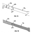
- FIG. 76 there is shown the cross sectional view of the endoscopic portion at the full stroke.
- a full stroke of the spindle 128 is required to take a clip 300 from an initial position to a fully inserted position in the jaws 16.
- the spindle 128 driven to a distal most position moves the driver bar 200 to crimp the clip.
- Fig. 77 through 79 shows the driver bar 200 having the camming surfaces 256 that engage other the first and the second raised camming surfaces 214, 216 being on each of the jaws 16a, 16b.
- the driver bar 200 rides the raised surfaces to close the jaws 16 with the clip 300 in the channel 24.
- Fig. 79 shows the driver bar 200 with a "T" shaped channel that closes over the camming raised surfaces 212, 214 of the jaws 16 to apply a compression on the clip 300 in the channel 24.
- the clip applier 10 has a security mechanism being provided to prevent an over stroke or excessive compression of the clip 300 in the channel 24 by the jaws 16 by squeezing. Such an excessive compression may cause one or more detriments such as an excessive compression of the clip 30 or damage to the driver bar 200, or the jaws 16. If the trigger 18 is continued to be squeezed past a full stroke required for a full forming of a clip 300 as shown in Fig. 81 , the impact spring 196 of Fig. 80 compresses in the spaced defined by the knob 20 and the bushing 156. The impact spring 196 prevents any further distal movement of the spindle 128 by absorbing force beyond what is required to close a clip on a vessel.
- the pawl 46 rotates against the bias of the pawl return spring 48 so the pawl tooth 178 ride along the rack 40 to reset the handle assembly 14 as shown by the reference arrow K.
- the drive member 36 retracts to reset.
- the rack 40 on the drive member 36 moves proximally and back under the pawl 46.
- the spindle 128 retracts to a proximal position and the latch member 206 is driven upwards opposite the spindle 128.
- the spindle 128 having the camming feature 210 retracts proximally and contacts the rotatable member 702 that rotates first proximal end 708 of the rotatable member 702 to contact the spring bar member 704 of the filler component 700.
- the wedge plate 600 does not retract as it has fully retracted already, and the proximal movement by the spindle 128 causes the cam link 208 to return to its original position. In this position, the clip applier 10 is again in an initial position to be refired and this to attach to another clip 300 to a vessel.
- the first rotatable member 102 will continue to ratchet through the teeth 116 of the lockout wheel 112.
- the lockout wheel 112 will progress and radially advance after each of the clips 300 is fired.
- the first rotatable member 102 will rotate until the pawl 106 will reach the escape notch 110 in the lockout wheel 112.
- the escape notch 110 will then allow the pawl 106 to traverse out from the lockout wheel 112 as shown by arrow K in Fig. 88 .
- the pawl 106 will then mate with a corresponding notch (A) shown in the trigger handle 18.
- the clip applier 10 will be locked and the pawl 106 will prevent any further firing or driving of the driving member 36 by the trigger 18.
- the clip applier 10 may be disposed in a suitable receptacle.
- the clip applier 10 is loaded with a number of clips 300 that exceed the number of teeth in the lockout wheel 112. To this end, the clip applier 10 cannot be dry fired without a clip therein.
- FIG. 90 there is shown an alternative embodiment of a number of components of the present clip applier 10. Referring to Fig. 90 , there is shown an exploded view of a wedge plate 750, a link cam 752, a filler component 754, and a spindle 756.
- the wedge plate 750 is similar to the embodiment shown previously and has a rounded distal end 758 and is suitably biased at the proximal end to the filler component 754.
- the rounded distal end 758 preferably moves in a distal manner as discussed to be disposed between the jaws 16 of the clip applier 10 for clip loading.
- the wedge plate 750 further has a link cam notch 760.
- the link cam notch 760 is in a substantially a mid-portion of the wedge plate 750.
- the link cam notch 760 is generally orthogonal shaped and is shaped into a lateral side of the wedge plate 750.
- the link cam notch 760 has a depth that is suitable to extend about to a middle of the wedge plate 750.
- the link cam notch 760 may have another shape or be circular or curved. Various configurations are possible and within the scope of the present disclosure.
- the link cam notch 760 preferably allows for the link cam 752 to engage and move the wedge plate 750 distally. The distal movement introduces the rounded distal end 758 between the jaws 16. Distal movement of the spindle 756 disengages the wedge plate 750 at a predetermined line of demarcation.
- the filler component 754 being shown above the wedge plate 750 in Fig. 90 does not move relative to the other components and is intended to remain stationary.
- the filler component 754 has a link cam aperture 762.
- the link cam aperture 762 is a circular shaped feature that is disposed in the filler component 754 to allow the link cam 752 access.
- the link cam aperture 762 is in a complementary location relative to the link cam notch 760 of the wedge plate 750. The location allows a portion of the link cam 752 to engage the link cam notch 760.
- the link cam 752 preferably has two discrete portions.
- the link cam 752 has a first base 764 and a second arm 766.
- the first base 764 rests and is rotatably mounted in the link cam aperture 762 of the filler component 754.
- the second arm 766 is connected to the first base 764.
- the second arm 766 is engageable with the link cam notch 760 of the wedge plate 750.
- the second arm 766 also has a post 767 that rides in a cam slot 768 of the spindle 756.
- the link cam 752 preferably has a portion that rotates to move another member a certain fixed distance, and then at the conclusion of the movement to return the member to its initial position.
- the spindle 756 is shown disposed below both the filler component 754 and the wedge plate 750 in Fig. 90 and has a cam slot 768.
- the cam slot 768 from a distal starting location 770 along the cam slot 768 to a proximal ending location 772, it is understood that the post 767 of the second arm 766 of the link cam 752 rides in the cam slot 768 and follows the precise path of the cam slot 768 as the spindle 756 advances distally through the stroke.
- the post 767 drives the wedge plate 750 in the cam slot 768 until a certain line of demarcation is reached, then a spring (not shown) or another biasing device of the link cam 752 retracts the post 767.
- Fig. 91 a there is shown the filler component 754 resting on the wedge plate 750 in an assembled state.
- the link cam aperture 762 is shown with the first base portion 764 being in the link cam aperture 762 of the filler component 754.
- the first base portion 764 can freely move or freely rotate in the link cam aperture 762 of the filler component 754.
- the first base portion 764 of the link cam 752 can rotate the second arm portion (not shown) underneath the filler component 754 with any desired degree range of rotation and with accuracy, and the clip applier 10 is not specifically limited to any specific amount of rotation.
- Fig. 91 b there is shown a view of the wedge plate 750 resting on the spindle 756 with the filler component 754 of Fig. 91 a being removed simply for illustration purposes only.
- the link cam 752 has the second arm 766 with the post (not shown) engaged to the link cam notch 760 of the wedge plate 750.
- the post 767 will urge the wedge plate 750 distally and notably will urge the rounded distal end 758 shown on the distal side between the jaws 16 for loading the clip.
- Fig. 91c there is shown the cam slot 768 of the spindle 756 in broken lines being beneath the wedge plate 750.
- the cam slot 768 will not disturb an orientation of the link cam 752.
- the second arm 766 will be cammed counterclockwise, and thus drive the wedge plate 750 by engaging and pushing the link cam notch 760 distally.
- the post 767 of the second arm 766 of the link cam 752 will traverse past the cam feature 774.
- the rounded distal end of the wedge plate 758 will be between the jaws 16 for loading.
- Fig. 92 there is shown a close up view of the link cam 754 along window 92 of FIG. 91 c in the cam slot 768 of the spindle 756.
- the link cam 754 will be driven into the proximal most location 770 of the cam slot 768.
- This proximal most location 770 of the cam slot 768 will permit retraction of the wedge plate 750 once the jaws 16 have been loaded and as the spindle 756 is continued to advance through the stroke for firing.
- the clip applier 10 in this embodiment has the signaling device 54.
- the signaling device 54 as discussed previously provides an indication to the surgeon that a surgical event has occurred, is occurring or will occur in the future.
- the surgical event may be any event associated with the clip applier 10, related to the surgical procedure, or both.
- the surgical event may be related to the number of available surgical clips remaining in the clip applier 10.
- the surgical event may be related to an indication of a time as to when the clip 300 is recommended to be fired.
- the surgical event may be related to or preventing any dry firing of the clip applier and the signaling device 54 may alert the surgeon that the number of surgical clips 300 in the clip applier 10 are too low and that a new clip applier 10 or another device should be procured.
- the surgical event may be other important or convenient parameters of the surgery such as a total time of surgery.
- the signaling device 54 preferably assist the surgeon with feedback of parameters that can not be readily seen, especially in tandem with using other endoscopic instruments.
- the first component 776 is a cylindrical shaped member.
- the first component 776 preferably has a proximal opening 778.
- the proximal opening 778 has a channel 780.
- the channel 780 also has first and second lateral sub channels 780a, and 780b that extend into the lateral sides of the first component 776.
- the proximal opening 778 also has an interior lateral surface 780c that is disposed to surround an interior of the channel 780.
- the first component 776 also has a distal side 782 having a camming feature 784.
- the distal side 782 has the camming feature 784 being a first and a second pointed ends 786, 788.
- Fig. 94 there is shown a top view of the first component 776.
- the first and the second pointed ends 786 and 788 protrude outward and away from the first component 776 at the distal side 782.
- the first component 776 also has a shelf 787.
- Fig. 95 there is shown a top view of the first component 776.
- the first component 776 (in this view) has the first and the second pointed ends 786, 788 extending outwardly from the distal side 782.
- Fig. 96 there is shown a view of the proximal opening 778 and channel 780.
- the channel 780 is suitably sized to permit another member access therein.
- the channel 780 also has the lateral sides with the first lateral sub channel 780a and the second lateral sub channel 780b.
- the second component 790 is a lever type structure and is capable of rotation about one rotational axis shown as reference A for illustration purposes.
- the second component 790 has a main post 792.
- the main post 792 sits on a base portion 794 has a camming surface 796, and is for insertion in the first component 776.
- the camming surface 796 has a suitable size to receive one of the first and the second pointed ends 786 and 788.
- the second component 790 rotates.
- the second component 790 also has another second post 902 and a third post 904.
- the second post 902 is connected to the main post 792 by a linkage 906 and the third post 904 is connected to the main post 792 by another second linkage 908.
- the main post 792 extends into the channel 780 of the first component 776 and the first pointed end 786 engages with a first sub recess 910 of the camming surface 796. Upon rotation, the first pointed end 786 of the first component 776 will ride in the cam surface 796 causing the first component 776 to move away from the second component 790.
- the first pointed end 786 will advantageously traverse from the first sub recess 910 to an adjacent second sub recess 912 when the first component 776 is rotated causing the first component 776 to move away from the second component 790 in a direction parallel to the longitudinal axis A.
- a rib portion 914 that extends inwardly and into the handle portion 12.
- the rib portion 914 is a cylindrical shaped feature.
- the rib portion 914 is preferably molded into the handle portion 12.
- the rib portion 914 has a lateral strip 916.
- the lateral strip 916 is an orthogonal shaped member that is integrally connected with the cylindrical shaped rib portion 914.
- Fig. 99 shows an interior view of an opposite lateral side of the handle portion 12 of the clip applier 10 that mates with a portion of the handle portion 12 shown in Fig. 98.
- Fig. 98 shows a partially assembled view of the signaling device 54 of the clip applier 10 having a spring 901 that rests on the shelf 787 of the first component 776.
- the lateral strip 916 of the rib portion 916 (shown in Fig. 98 ) engages and is disposed through the first cylindrical portion 776.
- the lateral strip 916 prevents the first component 776. from rotating.
- the lateral strip 916 contacts and prevents the first component from moving due to contact with a lateral side of the first lateral sub channel 780a.
- the driver bar 918 is connected to actuator plate 920.
- the actuator plate 920 in this embodiment has a notch 922 on a proximal side thereof.
- the notch 922 engages the second post 902 of the second component 790.
- the actuator plate 920 having the notch 922 will also rotate the second post 902 of the second component 790 (shown in Fig. 97 ).
- the second component 790 will likewise rotate in a counter clockwise manner thereby rotating the cam notch 796 (shown in Fig. 97 ).
- the cam notch 796 (shown in Fig.
- Fig. 100 illustrates a clip 300 applied to a vessel.
- the clip applier 1010 includes a lockout device.
- the lockout device is located in the handle portion 12 of the instrument 1010, and locks operation of one or more subassemblies of the instrument 1010.
- the lockout device is configured to prevent activation of the instrument irrespective of the force applied to the trigger 14.
- the lockout device in this embodiment prevents the spindle 128 from moving longitudinally.
- the driver bar 200 (or other subcomponents thereof) can not crimp a clip between the jaws 16a, 16b when there are no remaining clips 300 in the clip applier 10.
- Fig. 101 a number of components of the lockout device will be shown and described.
- Fig. 101 illustrates that the clip applier 1010 has a spring 1100 that is disposed in a predetermined location of a clip carrying channel 1102 ( Fig. 102 ).
- the spring 1100 may be disposed in other areas of the clip applier 1010, such as in a magazine, or with an embodiment where the clip applier 1010 does not include a clip carrying channel 1102, the spring 1100 may be disposed or located in other areas.
- the spring 1100 has a first cantilevered free end 1108 and an opposite end 1104. End 1104 is adapted to receive a lockout bar 1106 (See Figs. 104 and 105 ).
- the clip carrying channel 1102 is reproduced in Fig. 102 and Fig. 103 in a top view. As can be understood, the distal side 1112 ( Fig. 103 ) of the channel 1102 has the aperture 1110.
- the clip applier 1010 also has a lockout bar 1106.
- the lockout bar 1106 is reproduced in Fig. 104 in a top view.
- the lockout bar 1106 includes a first end 1114, and a second opposite hook end 1116.
- the lockout bar 1106 is sufficiently sized so as to be wedged between a ceiling and a floor of the clip carrying channel 1102. In another embodiment, the bar may be wedged between a ceiling and a floor of a clip magazine.
- the groove in the second hook end 1116 is adapted to engage a clip follower 1118 ( Fig. 115 ) of the clip applier 1010.
- the lockout bar 1106 may be removably or permanently connected to the clip follower 1118 by other methods such as a snap-fit arrangement, a friction-fit arrangement, a screw-fit arrangement, a pin arrangement, or any other arrangement such that first end 1114 may move.
- the lockout bar 1106 is retained between the bottom of the channel cover and the floor 1102' of the clip carrying channel 1102.
- the lockout bar 1106 rests in a distal slot 1117 formed in the clip follower 1118 (as shown in Fig. 115 ).
- the slot 1117 is shown as generally orthogonal, but may have any similar or different shape known in the art to permit the components to rest in the clip follower 1118.
- the lockout bar 1106 does not by itself lockout the clip applier 1010, but instead merely moves upwardly through the clip carrying channel 1102 when there are little or no remaining clips 300 in the clip carrying channel 1102.
- Fig. 106 illustrates a partially assembled view of the lockout spring 1100 with the lockout bar 1106.
- clip follower 1118 biases a stack of clips 300 in a clip carrying channel 1102 in a distal manner so the clips 300 may be available to be loaded between the jaws 1016a, 10166b in order to be applied to tissue as shown in Fig. 100 .
- the clip follower 1118 has a distal slot 1117 ( Fig. 107 ).
- the lockout bar 1106 is adapted to be received in the slot 1117 and move distally with the clip follower 1118 each time the clip applier instrument 1010 is fired, and the clip follower 1118 is advanced distally.
- Fig. 108 shows that the clip applier 1010 has a feed bar 1120.
- the feed bar 1120 reciprocates distally, then proximally during each stroke of the firing trigger to load a single clip 300 between the jaws 1016a, 1016b ( Fig. 111 ) of the clip applier 1010.
- the feed bar 1120 has a distal window 1122.
- the feed bar 1120 is made from a thin metallic material and is moved distally by a trip lever (not shown) and trip lever spring (not shown) as previously discussed with regard to the embodiment above.
- the feed bar 1120 is advantageously disposed above the clip follower 1118 (shown in Fig. 110 ) and the clip carrying channel 1102 (shown in Fig. 112 ).
- the proximal end of the feed bar 1120 has a pair of fins 1119 ( Fig. 108 ).
- the fins 1119 engage a proximal window 1134 of a spindle 1132 of the clip applier 1010 ( Fig. 117 ).
- the proximal end of the feed bar 1120 may have a single fin, or a member which engages window 1134 (or a particular) slot of the spindle 1132.
- FIG. 110 shows a side view of the components of the clip applier 10 with the clip follower 1118 in its distal most position, and the cover of the clip applier 1010 removed for illustration purposes.
- the feed bar 1120 includes a distal nose 1128 which advances the clips between the jaws (not shown).
- the feed bar 1120 also has a distal window 1122.
- the clip follower 1118 is positioned beneath the feed bar 1120 and has a slot 1117.
- the lockout bar 1106 is positioned in the slot 1117 of the clip follower 1118. As shown in Fig. 110 , in the distal most position, the lockout bar 1106 will deflect upward and engage window 1122 of the feed bar 1120.
- Fig. 111 shows a top perspective view of the components of the clip applier 1010.
- the clip applier 1010 has a first jaw 1016a, a second jaw 1016b, a stop 1018 connected to a cover 1020, and a feed bar 1120.
- Feed bar 1120 has the distal window 1122.
- the lockout bar 1106 extends into the distal window 1122 when the follower 1118 is in its distal most position, i.e., when there are no remaining clips.
- the lockout bar 1106 extends into the distal window 1122 when the follower 1118 is in its partially distal most position, i.e., when there are little remaining clips such as one, two, or three remaining clips.
- Various arrangements and position of the window 1122 are possible and within the scope of the present disclosure, and it should be appreciated that the window 1122 can be placed at varied locations to lockout the clip applier 1010 with any number of remaining clips in the clip applier 1010.
- Fig. 112 shows a top perspective view of the components of the clip applier 1010 with the cover 1020 of Fig. 111 removed and showing the nose 1128 of the feed bar 1120.
- the clip follower 1118 is in the clip carrying channel 1102 and will advance clips in a distal direction until it reaches its distal most position as shown.
- the clip follower 1118 is in the distal most position (as an example for illustration purposes) when there are no remaining clips in the clip carrying channel 1102 or available to be fired by the clip applier 1010.
- the feed bar 1120 having the distal window 1122 in this distal most position aligns with the lockout bar 1106.
- the lockout bar 1106 in this distal most position will be deflected upwardly and extend though the distal window 1122.
- Fig. 113 shows a top perspective view of the components of the clip applier 1010 with the cover 1020 and the feed bar 1120 both removed for illustration purposes to show the relationship between the lockout bar 1106 and the clip follower 1118.
- the clip carrying channel 1102 has a number of fingers 1103" on the lateral sides of the clip carrying channel 1102 to maintain the clips (not shown) aligned in the clip carrying channel 1102.
- Clip follower 1118 is positioned in the clip carrying channel 1102.
- the lockout bar 1106 is shown positioned in the slot 1117. It should be appreciated the lockout bar 1106 and the slot 1117 may have different shapes and geometries, and the present disclosure is not limited to any particular shape or geometry. It should further be appreciated the follower 1118 and the lockout bar 1106 may be formed as an integral member with one another. Various configurations are possible and within the scope of the present disclosure.
- Fig. 114 there is shown a bottom view of the clip follower 1118.
- the clip follower 1118 is shown as having the slot 1117 being generally orthogonal shaped and disposed along a longitudinal axis A of the clip follower 1118.
- the lockout spring 1100 biases the bar 1106.
- the lockout spring 1100 has a bulbous member 1108' at end 1108. The bulbous member 1108' of spring 1100 is large enough so as to pass over and avoid being caught in the aperture 1110 in the clip carrying channel 1102 (shown in Fig. 103 ).
- FIG. 115 there is shown a cross sectional view of the clip follower 1118 having the lockout bar 1106 positioned in the slot 1117 of the clip follower 1118. The view is taken along section line 116-116 of Fig. 114 .
- Slot 1117 of the clip follower 1118 has a pin 1117a that is disposed in the groove on the hook portion 1116 of the lockout bar 1106. Pin 1117a prevents the lockout bar 1106 from being separated from the clip follower 1118 during distal movement.
- lockout spring 1100 Disposed underneath the lockout bar 1106 is the lockout spring 1100 that biases the lockout bar 1106 in a direction opposite the clip carrying channel 1102 as shown in Fig. 114 . Prior to the last clip being applied, the lockout bar 1106 is retained between the bottom surface of the channel cover and the floor 1102' of the clip carrying channel 1102.
- Fig. 110 illustrates that at the distal most position of the clip follower 1118, the lockout spring 1100 will move and rotate the free end 1114 of the lockout bar 1106 to a position extending above the clip carrying channel 1102.
- the free end 1114 of the lockout bar 1106 will rotate upward and escape through the ceiling 1103' of the clip carrying channel 1102 at the distal position of the clip follower 1118 to engage the distal most window 1122 of the feed bar 1120 as shown in Fig. 110 .
- the hook portion 1116 of the lockout bar 1106 will rotate down and engage aperture 1110 in the floor of the clip carrying channel 1102.
- the distal window 1122 of the feed bar 1120 is shown above immediately adjacent to the nose 1128 of the feed bar 1120 ( Fig. 116 ).
- the free end 1114 of the lockout bar 1106 of Fig. 110 will move above and through the clip carrying channel 1102 and will engage the distal window 1122 of the feed bar 1120 as shown in Fig. 110 .
- a spindle 1132 is shown in Figs. 117 and 118 .
- the window 1134 is suitably sized and positioned such that the fins 1119 of the feed bar 1120 (shown in Fig. 108 ) simply rest in the window 1134 of the spindle 1132 during normal operation of the clip applier 1010 without effecting the distal or proximal movement of the spindle 1132.
- the window 1134 is shown in an enlarged view in Fig. 119 .
- the window 1134 has a generally orthogonal shape and the outer lateral surface of the window 1134 will not interfere or contact other components during the normal operation of the clip applier 1010.
- the feed bar 1120 (shown in Fig. 108 ) is a thin member relative to the spindle 1132 of Fig. 119 .
- the feed bar 1120 is a thin metallic member.
- the feed bar 1120 is a thin thermoplastic member.
- the feed bar 1120 is suitable for reciprocation distally and proximally relative to the spindle 1132. When the fins 1119 hook the distal edge of window 1134 of spindle 1132, the feed bar 1120 prevents retraction but not advancement of the spindle 1132.
- the pawl 1146 in the handle portion cannot return to the home or initial position relative to the rack 1140 in the handle portion 12 of the clip applier 1010. Instead, as shown in Fig. 121 , the pawl 1146 will remain in an intermediate position relative to the rack 1140.
- the trigger (not shown) is squeezed, pawl 1146 cannot rotate enough to be free of the rack 1140 or move clockwise to reset the pawl 1146 to the home (or at rest position for the next firing of the instrument as shown in Fig. 120 ).
- the pawl 1146 and rack 1136 lockout the trigger 14 from being squeezed and the spindle 1132 cannot move distally to engage the driver bar ( Fig. 26 and 27 ) and subsequently the clip applier 1010 is unable to close the jaws 1016a, 1016b.
- the surgeon will feel a strong tactile feedback from the trigger 14 and resistance that the trigger 14 cannot be compressed toward the handle 12 any further, thus signaling that the clip applier 1010 needs to be disposed/replaced with a new instrument.
- a shear pin 1148 for a secondary lockout mechanism 1150 is a generally cylindrical member having a three-part body 1152 defining a first neck portion 1154 and a second neck portion 1156.
- the first neck portion and the second neck portion 1154, 1156 respectively have a width that is less than a width of the body 1152 and are configured to engage a linkage 1160.
- trigger 1156 is connected to linkage 1160, which, in turn, engages the first and the second neck portions 1154 and 1156 of pin 1148.
- Fig. 123 there is shown a side cross sectional view of the clip applier 1010 having the rack 1140 and pawl 1146 locking out the spindle 1132 as described above with the secondary lockout mechanism 1150.
- the trigger 1156 will be prevented from advancing the spindle 1132 distally since the rack 1140 and the pawl 1146 prevent the spindle 1132 from retracting proximally as discussed above.
- the instrument 1010 has a secondary lockout 1150 to prevent the surgeon from placing too much force on the trigger 1156 and the handle 1158 which could possibly overcome or dislodge the engagement between the rack 1140 and the pawl 1146, and move the spindle 1132 distally.
- a force F1 placed on the trigger 1156, the trigger 1156 will move toward the handle 1158 to advance the link 1160.
- the link 1160 will advance the shear pin 1148 distally to advance the spindle 1132 distally by spindle link 1132a.
- the engagement between the pawl 1146 and the rack 1140 will prevent the spindle 1132 from moving distally as discussed above.
- a force F2 that is greater than the force F1
- the force F2 will break shear pin 1148.
- the connection between the trigger 1156 and the spindle 1132 is broken and the link 1160 cannot advance the spindle link 1132a distally.
- a secondary lockout is achieved.
Landscapes
- Health & Medical Sciences (AREA)
- Surgery (AREA)
- Life Sciences & Earth Sciences (AREA)
- Heart & Thoracic Surgery (AREA)
- Nuclear Medicine, Radiotherapy & Molecular Imaging (AREA)
- Vascular Medicine (AREA)
- Engineering & Computer Science (AREA)
- Biomedical Technology (AREA)
- Reproductive Health (AREA)
- Medical Informatics (AREA)
- Molecular Biology (AREA)
- Animal Behavior & Ethology (AREA)
- General Health & Medical Sciences (AREA)
- Public Health (AREA)
- Veterinary Medicine (AREA)
- Surgical Instruments (AREA)
Claims (26)
- Vorrichtung (1010) zur Applikation von chirurgischen Klammern auf ein Körpergewebe, die aufweist:a) einen Handgriffabschnitt (1158),b) ein Gehäuse (14), das sich distal von dem Handgriffabschnitt (1158) erstreckt und eine Längsachse bildet,c) eine Mehrzahl von chirurgischen Klammern (300), die in dem Gehäuse (14) angeordnet sind,d) eine Klemmbackenanordnung (16), die neben einem distalen Endabschnitt des Gehäuses (14) befestigt ist, wobei die Klemmbackenanordnung (16) erste und zweite Klemmbackenabschnitte (1016,a, 1016b) aufweist, die zwischen einer beabstandeten und einer angenäherten Position bewegbar sind,e) eine Zuführstange (1120) mit einem distalen Fenster (1122) und die so eingerichtet ist, dass sie eine einzelne der chirurgischen Klammern (300) distal zu der Klemmbackenanordnung (16) voranbringt, während die Klemmbackenabschnitte (1016a, 1016b) in der voneinander beabstandeten Position sind,f) einen Klammerdrücker (1118), der proximal zu der Mehrzahl von Klammern (300) angeordnet ist und so eingerichtet ist, dass er die Mehrzahl von Klammern (300) in einer distalen Weise vorspannt,g) ein Betätigungselement (1132), das zumindest teilweise in dem Gehäuse (14) angeordnet ist und als Reaktion auf eine Betätigung des Handgriffabschnitts (1158) in Längsrichtung bewegbar ist,h) ein Klemmbackenverschlusselement (200), das neben den ersten und zweiten Klemmbackenabschnitten (1016a, 1016b) angeordnet ist, um die Klemmbackenabschnite (1016a, 1016b) in die angenäherte Position zu bewegen,i) einen Einschub (1140) mit einer Mehrzahl von Sperrzähnen (44), der mit dem Betätigungselement (1132) verbunden ist, undj) eine Klinke (1146) mit mindestens einem Zahn (178), der so eingerichtet ist, dass er in die Sperrzähne (44) eingreift, wobei die Klinke (1146) in dem Handgriffabschnitt (1158) vorgespannt ist, wobei, wenn das Betätigungselement (1132) in Längsrichtung bewegt wird, die Mehrzahl von Sperrzähnen (44) über die Klinke (1146) passieren, wobei die Klinke (1146) so eingerichtet ist, dass sie eine versehentliche Rückkehr des Betätigungselements (1132) vor der vollständigen Betätigung der Vorrichtung (1010) verhindert,
dadurch gekennzeichnet,
dass der Klammerschieber (1118) sich schrittweise distal bewegt jedes Mal, wenn eine der Klammern (300) von der Vorrichtung (1010) freigegeben wird, dass, wenn der Klammerschieber (1118) einen vorbestimmten distalen Punkt in einem die Klammern tragenden Kanal (1102) erreicht, eine Sperrstange (1106) in eine zweite Position in Eingriff mit dem distalen Fenster (1122) der Zuführstange (1120) ausgelenkt wird, wobei die Zuführstange (1120) einen Abschnitt aufweist, der mit dem Betätigungselement (1132) in Eingriff ist, und ein Zurückziehen des Betätigungselements (1132) verhindert, nicht aber ein Voranschreiten, und dadurch die Klinke (1146) bedient, so dass sie mit den Sperrzähnen (44) des Einschubs (1140) in Eingriff ist, wobei die Klinke (1146) und der Einschub (1140) verhindern, dass das Betätigungselement (1132) sich in Längsrichtung bewegt und so das Betätigungselement (1132) blockiert, und
dass die Vorrichtung darüber hinaus aufweist:k) eine Sekundärsperreinrichtung, die so eingerichtet ist, dass sie eine Verbindung zwischen dem Handgriffabschnitt (1158) und dem Betätigungselement (1132) unterbricht und eine Längsbewegung des Betätigungselements (1132) als Reaktion auf eine Betätigung des Handgriffabschnitts (1158) verhindert, wenn eine vorbestimmte Kraft an den Handgriffabschnitt (1158) angelegt wird, wobei die vorbestimmte Kraft geringer ist als die benötigte Kraft, um die Sperrzähne (44) von der Klinke (1146) zu entfernen. - Vorrichtung (1010) nach Anspruch 1, wobei die Sekundärsperreinrichtung ein Gelenk (1160) aufweist, das das Betätigungselement (1132) mit dem Handgriffabschnitt (1158) verbindet, und einen Scherstift (1448), der das Gelenk mit dem Betätigungselement (1132) verbindet.
- Vorrichtung (1010) nach Anspruch 2, wobei der Scherstift (1448) im Allgemeinen zylindrisch ist und einen Körper (1152) mit einem ersten Durchmesser und einem zweiten Abschnitt (1154, 1156), der einen zweiten Durchmesser aufweist, der geringer ist als der erste Durchmesser, aufweist, wobei bei Anwendung der vorbestimmten Kraft der Scherstift (1448) entlang des zweiten Durchmessers bricht.
- Vorrichtung nach Anspruch 1, wobei die Sperrstange (1106) durch eine Feder (1100) vorgespannt und zwischen einer Decke und einem Boden des die Klammern tragenden Kanals (1102) angeordnet ist, wobei der Klammerschieber (1118) die Sperrstange (1106) distal bewegt und wobei, wenn die Sperrstange (1106) im Wesentlichen mit dem distalen Fenster (1100) ausgerichtet ist, die Sperrstange (1106) sich durch das distale Fenster (1122) in die zweite ausgelenkte Position bewegt.
- Vorrichtung (1010) nach Anspruch 4, wobei die Zuführstange (1120) eine proximale Rippe (1119) aufweist, wobei die Rippe (1119) so eingerichtet ist, dass sie verhindert, dass das Betätigungselement (1132) sich proximal in die zweite ausgelenkte Position bewegt.
- Vorrichtung (1010) nach Anspruch 4, wobei die Zuführstange (1120) ein Paar von proximalen Rippen (1119) aufweist, wobei mindestens eine so eingerichtet ist, dass sie verhindert, dass das Betätigungselement (1132) sich proximal in die zweite Position bewegt.
- Vorrichtung (1010) nach Anspruch 4, wobei die Zuführstange (1120) ein Paar von proximalen Rippen (1119) aufweist, wobei das Paar verbunden ist und eine "U"-Form aufweist, wobei mindestens eine so eingerichtet ist, dass sie verhindert, dass das Betätigungselement (1132) sich proximal in die zweite Position bewegt.
- Vorrichtung (1010) nach Anspruch 5, wobei das Betätigungselement (1132) ein proximales Fenster (1134) aufweist, wobei die Rippe (1119) mit dem Fenster (1134) in Eingriff ist, um zu verhindern, dass sich das Betätigungselement (1132) proximal in die zweite ausgelenkte Position bewegt.
- Vorrichtung (1010) nach Anspruch 4, wobei die Feder (1100) und die Sperrstange (1106) in einem Kanal (1117) des Klammerschiebers (1118) angeordnet sind, wobei die Feder (1100) unter der Sperrstange (1106) angeordnet ist.
- Vorrichtung (1010) nach Anspruch 4, wobei die Sperrstange (1106) ein elastisches Element ist.
- Vorrichtung (1010) nach Anspruch 4, wobei das Einschubelement (1140) und die Klinke (1146) in dem Handgriffabschnitt (1158) angeordnet sind.
- Vorrichtung (1010) nach Anspruch 4, wobei das Einschubelement (1110) mit der Mehrzahl von Sperrzähnen (44) mit dem Handgriffabschnitt (1158) verbunden ist und wobei die Klinke (1146) mit dem Betätigungselement (1132) verbunden ist.
- Vorrichtung (1010) nach Anspruch 4, wobei das distale Fenster (1122) an einem Ende des die Klammern tragenden Kanals (1102) angeordnet ist.
- Vorrichtung (1010) nach Anspruch 4, wobei die Klinke (1146) mit dem Einschubelement (1140) in Eingriff ist und wobei die Klinke (1146) und das Einschubelement (1140) verhindern, dass das Betätigungselement (1132) sich in Längsrichtung bewegt, wenn sich keine Klammern (300) in dem die Kammern tragenden Kanal (1102) befinden.
- Vorrichtung (1010) nach Anspruch 5, wobei die Klinke (1146) mit dem Einschubelement (1140) in Eingriff ist und die Klinke (1146) und das Einschubelement (1140) verhindern, dass das Betätigungselement (1132) sich in Längsrichtung bewegt, wenn sich zwei Klammern aus der Mehrzahl von Klammern (300) in dem die Klammern tragenden Kanal (1102) befinden.
- Vorrichtung (1010) nach Anspruch 4, wobei die Zuführstange (1120) in der zweiten ausgelenkten Position ist und wobei die Zuführstange (1120) verhindert, dass sich das Betätigungselement (1132) proximal bewegt und dadurch die Klemmbacken (1146) so beeinflusst, dass sie mit den Zähnen (44) des Einschubelements (1140) in einer im Wesentlichen Zwischenposition des Einschubelements (1140) in Eingriff kommt, wobei die Klinke (1146) und das Einschubelement (1140) in Eingriff sind, wobei der Eingriff dadurch verhindert, dass sich das Betätigungselement (1132) in Längsrichtung bewegt.
- Vorrichtung (1010) nach Anspruch 4, wobei in der zweiten ausgelenkten Position die Zuführstange (1120) nicht parallel zu der Längsachse ist.
- Vorrichtung (1010) nach Anspruch 4, wobei die Zuführstange (1120) sich aus einer anfänglichen Position in die zweite Position bewegt, wobei die zweite Position eine Position ist, die gegenüber der Längsachse ausgelenkt ist.
- Vorrichtung (1010) nach Anspruch 1, wobei das Betätigungselement (1132) eine Spindel (1132) aufweist.
- Vorrichtung (1010) nach Anspruch 5, wobei die Feder (1100) eine Blattfeder (1100) ist, wobei die Blattfeder (1100) und die Sperrstange (1106) in einem Kanal (1117) angeordnet sind, der distal von dem Klammerschieber (1118) angeordnet ist, wobei die Blattfeder (1100) unter der Sperrstange (1106) angeordnet ist und so eingerichtet ist, dass sie die Sperrstange (1106) relativ zu dem Boden des die Klammern tragenden Kanals (1102) nach oben vorspannt.
- Vorrichtung (1010) nach Anspruch 20,wobei die Sperrstange (1106) ein hakenförmiges proximales Ende (1116) aufweist, das mit einem Abschnitt des Klammerschiebers (1118) in dem Kanal in Eingriff tritt, so dass die Sperrstange (1106) sich distal mit dem Klammerschieber (1118) bewegt.
- Vorrichtung (1010) nach Anspruch 21, wobei das proximale hakenförmige Ende (1116) mit einer Öffnung (1114) auf dem Boden in Eingriff tritt, um die Sperrstange (1106) nach oben relativ zu dem Boden des Klammer tragenden Kanals (1102) zu bewegen und wobei, wenn die Sperrstange (1106) mit dem distalen Fenster (1110) des Klammer tragenden Kanals (1102) ausgerichtet ist, das proximale hakenförmige Ende (1116) mit einer in einem Boden des die Klammern tragenden Kanals (1102) angeordneten Öffnung in Eingriff tritt.
- Vorrichtung (1010) nach Anspruch 22, wobei die proximale Rippe (1119) auf dem proximalen Fenster (1134) ruht und nicht mit der Bewegung des Betätigungselements (1132) wechselwirkt, wenn das Betätigungselement (1132) sich in Längsrichtung während eines Auslösehubs hin und her bewegt.
- Vorrichtung (1010) nach Anspruch 1, wobei die Vorrichtung (1010) für endoskopische chirurgische Anwendungen eingerichtet ist.
- Vorrichtung (1010) nach Anspruch 24, wobei das Gehäuse (14) der Vorrichtung (1010 für operative Magenverkleinerungen eingerichtet ist.
- Vorrichtung (1010) nach Anspruch 24, wobei das Gehäuse (14) eine Länge von mindestens dreißig Zentimetern aufweist.
Priority Applications (1)
| Application Number | Priority Date | Filing Date | Title |
|---|---|---|---|
| EP10192623A EP2301448B1 (de) | 2006-10-02 | 2007-09-26 | Endoskopischer chirurgischer Klammerapplikator |
Applications Claiming Priority (1)
| Application Number | Priority Date | Filing Date | Title |
|---|---|---|---|
| US11/541,617 US7819886B2 (en) | 2004-10-08 | 2006-10-02 | Endoscopic surgical clip applier |
Related Child Applications (1)
| Application Number | Title | Priority Date | Filing Date |
|---|---|---|---|
| EP10192623.6 Division-Into | 2010-11-25 |
Publications (3)
| Publication Number | Publication Date |
|---|---|
| EP1908423A2 EP1908423A2 (de) | 2008-04-09 |
| EP1908423A3 EP1908423A3 (de) | 2008-12-24 |
| EP1908423B1 true EP1908423B1 (de) | 2011-01-26 |
Family
ID=38950765
Family Applications (2)
| Application Number | Title | Priority Date | Filing Date |
|---|---|---|---|
| EP10192623A Not-in-force EP2301448B1 (de) | 2006-10-02 | 2007-09-26 | Endoskopischer chirurgischer Klammerapplikator |
| EP07253807A Not-in-force EP1908423B1 (de) | 2006-10-02 | 2007-09-26 | Endoskopischer chirurgischer Klammerapplikator |
Family Applications Before (1)
| Application Number | Title | Priority Date | Filing Date |
|---|---|---|---|
| EP10192623A Not-in-force EP2301448B1 (de) | 2006-10-02 | 2007-09-26 | Endoskopischer chirurgischer Klammerapplikator |
Country Status (7)
| Country | Link |
|---|---|
| US (2) | US7819886B2 (de) |
| EP (2) | EP2301448B1 (de) |
| JP (2) | JP5214943B2 (de) |
| AU (1) | AU2007216891B2 (de) |
| CA (1) | CA2604975C (de) |
| DE (1) | DE602007012184D1 (de) |
| ES (2) | ES2391171T3 (de) |
Cited By (25)
| Publication number | Priority date | Publication date | Assignee | Title |
|---|---|---|---|---|
| US8267944B2 (en) | 2008-08-29 | 2012-09-18 | Tyco Healthcare Group Lp | Endoscopic surgical clip applier with lock out |
| US8357171B2 (en) | 2004-10-08 | 2013-01-22 | Covidien Lp | Endoscopic surgical clip applier |
| US8439244B2 (en) | 2010-01-20 | 2013-05-14 | Ethicon Endo-Surgery, Inc. | Surgical stapler fastening device with movable anvil |
| US8453905B2 (en) | 2009-01-26 | 2013-06-04 | Ethicon Endo-Surgery, Inc. | Surgical fastener for applying a large staple through a small delivery port |
| US8469252B2 (en) | 2009-01-26 | 2013-06-25 | Ethicon Endo-Surgery, Inc. | Surgical stapler fastening device with adjustable anvil |
| US8602286B2 (en) | 2009-01-26 | 2013-12-10 | Ethicon Endo-Surgery, Inc. | Apparatus for feeding staples in a low profile surgical stapler |
| US8734469B2 (en) | 2009-10-13 | 2014-05-27 | Covidien Lp | Suture clip applier |
| US8747423B2 (en) | 2007-03-26 | 2014-06-10 | Covidien Lp | Endoscopic surgical clip applier |
| US8801732B2 (en) | 2009-01-26 | 2014-08-12 | Ethicon Endo-Surgery, Inc. | Surgical stapler to secure a tissue fold |
| US8845659B2 (en) | 2010-02-25 | 2014-09-30 | Covidien Lp | Articulating endoscopic surgical clip applier |
| US8894665B2 (en) | 2008-08-29 | 2014-11-25 | Covidien Lp | Endoscopic surgical clip applier |
| US8920438B2 (en) | 2004-10-08 | 2014-12-30 | Covidien Lp | Apparatus for applying surgical clips |
| US8961542B2 (en) | 2010-07-28 | 2015-02-24 | Covidien Lp | Articulating clip applier cartridge |
| US8968337B2 (en) | 2010-07-28 | 2015-03-03 | Covidien Lp | Articulating clip applier |
| US9011464B2 (en) | 2010-11-02 | 2015-04-21 | Covidien Lp | Self-centering clip and jaw |
| US9113892B2 (en) | 2013-01-08 | 2015-08-25 | Covidien Lp | Surgical clip applier |
| US9186136B2 (en) | 2009-12-09 | 2015-11-17 | Covidien Lp | Surgical clip applier |
| US9186153B2 (en) | 2011-01-31 | 2015-11-17 | Covidien Lp | Locking cam driver and jaw assembly for clip applier |
| US9358015B2 (en) | 2008-08-29 | 2016-06-07 | Covidien Lp | Endoscopic surgical clip applier with wedge plate |
| US9364216B2 (en) | 2011-12-29 | 2016-06-14 | Covidien Lp | Surgical clip applier with integrated clip counter |
| US9364239B2 (en) | 2011-12-19 | 2016-06-14 | Covidien Lp | Jaw closure mechanism for a surgical clip applier |
| US9408610B2 (en) | 2012-05-04 | 2016-08-09 | Covidien Lp | Surgical clip applier with dissector |
| US9498227B2 (en) | 2007-04-11 | 2016-11-22 | Covidien Lp | Surgical clip applier |
| US9532787B2 (en) | 2012-05-31 | 2017-01-03 | Covidien Lp | Endoscopic clip applier |
| US9713471B2 (en) | 2009-01-26 | 2017-07-25 | Ethicon Endo-Surgery, Inc. | Surgical device with tandem fasteners |
Families Citing this family (625)
| Publication number | Priority date | Publication date | Assignee | Title |
|---|---|---|---|---|
| CA2481284C (en) | 2002-04-10 | 2010-09-21 | Tyco Healthcare Group Lp | Surgical clip applier with high torque jaws |
| WO2004080290A2 (en) | 2003-03-11 | 2004-09-23 | Tyco Healthcare Group, Lp | Clip applying apparatus with angled jaw |
| WO2004091377A2 (en) * | 2003-03-28 | 2004-10-28 | Downey Earl C | Surgical instrument with trigger control |
| US9060770B2 (en) | 2003-05-20 | 2015-06-23 | Ethicon Endo-Surgery, Inc. | Robotically-driven surgical instrument with E-beam driver |
| US20070084897A1 (en) | 2003-05-20 | 2007-04-19 | Shelton Frederick E Iv | Articulating surgical stapling instrument incorporating a two-piece e-beam firing mechanism |
| US7875040B2 (en) * | 2003-10-15 | 2011-01-25 | Femcare Limited | Visual indication of a trigger intermediate position on an applicator |
| US8215531B2 (en) | 2004-07-28 | 2012-07-10 | Ethicon Endo-Surgery, Inc. | Surgical stapling instrument having a medical substance dispenser |
| US9072535B2 (en) | 2011-05-27 | 2015-07-07 | Ethicon Endo-Surgery, Inc. | Surgical stapling instruments with rotatable staple deployment arrangements |
| US11890012B2 (en) | 2004-07-28 | 2024-02-06 | Cilag Gmbh International | Staple cartridge comprising cartridge body and attached support |
| US11998198B2 (en) | 2004-07-28 | 2024-06-04 | Cilag Gmbh International | Surgical stapling instrument incorporating a two-piece E-beam firing mechanism |
| US7819886B2 (en) | 2004-10-08 | 2010-10-26 | Tyco Healthcare Group Lp | Endoscopic surgical clip applier |
| US8409222B2 (en) * | 2004-10-08 | 2013-04-02 | Covidien Lp | Endoscopic surgical clip applier |
| US9763668B2 (en) | 2004-10-08 | 2017-09-19 | Covidien Lp | Endoscopic surgical clip applier |
| US7669746B2 (en) | 2005-08-31 | 2010-03-02 | Ethicon Endo-Surgery, Inc. | Staple cartridges for forming staples having differing formed staple heights |
| US11246590B2 (en) | 2005-08-31 | 2022-02-15 | Cilag Gmbh International | Staple cartridge including staple drivers having different unfired heights |
| US11484312B2 (en) | 2005-08-31 | 2022-11-01 | Cilag Gmbh International | Staple cartridge comprising a staple driver arrangement |
| US7934630B2 (en) | 2005-08-31 | 2011-05-03 | Ethicon Endo-Surgery, Inc. | Staple cartridges for forming staples having differing formed staple heights |
| US9237891B2 (en) | 2005-08-31 | 2016-01-19 | Ethicon Endo-Surgery, Inc. | Robotically-controlled surgical stapling devices that produce formed staples having different lengths |
| US10159482B2 (en) | 2005-08-31 | 2018-12-25 | Ethicon Llc | Fastener cartridge assembly comprising a fixed anvil and different staple heights |
| US7673781B2 (en) | 2005-08-31 | 2010-03-09 | Ethicon Endo-Surgery, Inc. | Surgical stapling device with staple driver that supports multiple wire diameter staples |
| US9326776B2 (en) * | 2005-09-29 | 2016-05-03 | Applied Medical Resources Corporation | Manually actuated surgical clip applier |
| US8080004B2 (en) * | 2005-10-26 | 2011-12-20 | Earl Downey | Laparoscopic surgical instrument |
| US20070106317A1 (en) | 2005-11-09 | 2007-05-10 | Shelton Frederick E Iv | Hydraulically and electrically actuated articulation joints for surgical instruments |
| US11793518B2 (en) | 2006-01-31 | 2023-10-24 | Cilag Gmbh International | Powered surgical instruments with firing system lockout arrangements |
| US20110024477A1 (en) | 2009-02-06 | 2011-02-03 | Hall Steven G | Driven Surgical Stapler Improvements |
| US8820603B2 (en) | 2006-01-31 | 2014-09-02 | Ethicon Endo-Surgery, Inc. | Accessing data stored in a memory of a surgical instrument |
| US20110290856A1 (en) | 2006-01-31 | 2011-12-01 | Ethicon Endo-Surgery, Inc. | Robotically-controlled surgical instrument with force-feedback capabilities |
| US8708213B2 (en) | 2006-01-31 | 2014-04-29 | Ethicon Endo-Surgery, Inc. | Surgical instrument having a feedback system |
| US7753904B2 (en) | 2006-01-31 | 2010-07-13 | Ethicon Endo-Surgery, Inc. | Endoscopic surgical instrument with a handle that can articulate with respect to the shaft |
| US7845537B2 (en) | 2006-01-31 | 2010-12-07 | Ethicon Endo-Surgery, Inc. | Surgical instrument having recording capabilities |
| US20120292367A1 (en) | 2006-01-31 | 2012-11-22 | Ethicon Endo-Surgery, Inc. | Robotically-controlled end effector |
| US11224427B2 (en) | 2006-01-31 | 2022-01-18 | Cilag Gmbh International | Surgical stapling system including a console and retraction assembly |
| US20110006101A1 (en) | 2009-02-06 | 2011-01-13 | EthiconEndo-Surgery, Inc. | Motor driven surgical fastener device with cutting member lockout arrangements |
| US11278279B2 (en) | 2006-01-31 | 2022-03-22 | Cilag Gmbh International | Surgical instrument assembly |
| US9861359B2 (en) | 2006-01-31 | 2018-01-09 | Ethicon Llc | Powered surgical instruments with firing system lockout arrangements |
| US8186555B2 (en) | 2006-01-31 | 2012-05-29 | Ethicon Endo-Surgery, Inc. | Motor-driven surgical cutting and fastening instrument with mechanical closure system |
| US20070225562A1 (en) | 2006-03-23 | 2007-09-27 | Ethicon Endo-Surgery, Inc. | Articulating endoscopic accessory channel |
| US8992422B2 (en) | 2006-03-23 | 2015-03-31 | Ethicon Endo-Surgery, Inc. | Robotically-controlled endoscopic accessory channel |
| EP2015681B1 (de) | 2006-05-03 | 2018-03-28 | Datascope Corp. | Gewebeverschlussvorrichtung |
| US8322455B2 (en) | 2006-06-27 | 2012-12-04 | Ethicon Endo-Surgery, Inc. | Manually driven surgical cutting and fastening instrument |
| US8485412B2 (en) | 2006-09-29 | 2013-07-16 | Ethicon Endo-Surgery, Inc. | Surgical staples having attached drivers and stapling instruments for deploying the same |
| US10130359B2 (en) | 2006-09-29 | 2018-11-20 | Ethicon Llc | Method for forming a staple |
| US10568652B2 (en) | 2006-09-29 | 2020-02-25 | Ethicon Llc | Surgical staples having attached drivers of different heights and stapling instruments for deploying the same |
| US11980366B2 (en) | 2006-10-03 | 2024-05-14 | Cilag Gmbh International | Surgical instrument |
| EP1913881B1 (de) | 2006-10-17 | 2014-06-11 | Covidien LP | Vorrichtung zum Setzen chirurgischer Klammern |
| US8632535B2 (en) | 2007-01-10 | 2014-01-21 | Ethicon Endo-Surgery, Inc. | Interlock and surgical instrument including same |
| US8684253B2 (en) | 2007-01-10 | 2014-04-01 | Ethicon Endo-Surgery, Inc. | Surgical instrument with wireless communication between a control unit of a robotic system and remote sensor |
| US8652120B2 (en) | 2007-01-10 | 2014-02-18 | Ethicon Endo-Surgery, Inc. | Surgical instrument with wireless communication between control unit and sensor transponders |
| US11291441B2 (en) | 2007-01-10 | 2022-04-05 | Cilag Gmbh International | Surgical instrument with wireless communication between control unit and remote sensor |
| US20080169332A1 (en) | 2007-01-11 | 2008-07-17 | Shelton Frederick E | Surgical stapling device with a curved cutting member |
| US11039836B2 (en) | 2007-01-11 | 2021-06-22 | Cilag Gmbh International | Staple cartridge for use with a surgical stapling instrument |
| US8727197B2 (en) | 2007-03-15 | 2014-05-20 | Ethicon Endo-Surgery, Inc. | Staple cartridge cavity configuration with cooperative surgical staple |
| US8893946B2 (en) | 2007-03-28 | 2014-11-25 | Ethicon Endo-Surgery, Inc. | Laparoscopic tissue thickness and clamp load measuring devices |
| US8931682B2 (en) | 2007-06-04 | 2015-01-13 | Ethicon Endo-Surgery, Inc. | Robotically-controlled shaft based rotary drive systems for surgical instruments |
| US11857181B2 (en) | 2007-06-04 | 2024-01-02 | Cilag Gmbh International | Robotically-controlled shaft based rotary drive systems for surgical instruments |
| US7753245B2 (en) | 2007-06-22 | 2010-07-13 | Ethicon Endo-Surgery, Inc. | Surgical stapling instruments |
| US8308040B2 (en) | 2007-06-22 | 2012-11-13 | Ethicon Endo-Surgery, Inc. | Surgical stapling instrument with an articulatable end effector |
| US11849941B2 (en) | 2007-06-29 | 2023-12-26 | Cilag Gmbh International | Staple cartridge having staple cavities extending at a transverse angle relative to a longitudinal cartridge axis |
| US20090043246A1 (en) * | 2007-08-07 | 2009-02-12 | Dominguez Guillermo Manuel | Magnetic Surgical Device to Manipulate Tissue in Laparoscopic Surgeries Performed with a Single Trocar or Via Natural Orifices |
| US20110046637A1 (en) * | 2008-01-14 | 2011-02-24 | The University Of Western Ontario | Sensorized medical instrument |
| US8561870B2 (en) | 2008-02-13 | 2013-10-22 | Ethicon Endo-Surgery, Inc. | Surgical stapling instrument |
| US7866527B2 (en) | 2008-02-14 | 2011-01-11 | Ethicon Endo-Surgery, Inc. | Surgical stapling apparatus with interlockable firing system |
| US8573465B2 (en) | 2008-02-14 | 2013-11-05 | Ethicon Endo-Surgery, Inc. | Robotically-controlled surgical end effector system with rotary actuated closure systems |
| US8657174B2 (en) | 2008-02-14 | 2014-02-25 | Ethicon Endo-Surgery, Inc. | Motorized surgical cutting and fastening instrument having handle based power source |
| US11986183B2 (en) | 2008-02-14 | 2024-05-21 | Cilag Gmbh International | Surgical cutting and fastening instrument comprising a plurality of sensors to measure an electrical parameter |
| US7819298B2 (en) | 2008-02-14 | 2010-10-26 | Ethicon Endo-Surgery, Inc. | Surgical stapling apparatus with control features operable with one hand |
| US8636736B2 (en) | 2008-02-14 | 2014-01-28 | Ethicon Endo-Surgery, Inc. | Motorized surgical cutting and fastening instrument |
| US9179912B2 (en) | 2008-02-14 | 2015-11-10 | Ethicon Endo-Surgery, Inc. | Robotically-controlled motorized surgical cutting and fastening instrument |
| RU2493788C2 (ru) | 2008-02-14 | 2013-09-27 | Этикон Эндо-Серджери, Инк. | Хирургический режущий и крепежный инструмент, имеющий радиочастотные электроды |
| US8758391B2 (en) | 2008-02-14 | 2014-06-24 | Ethicon Endo-Surgery, Inc. | Interchangeable tools for surgical instruments |
| US20130153641A1 (en) | 2008-02-15 | 2013-06-20 | Ethicon Endo-Surgery, Inc. | Releasable layer of material and surgical end effector having the same |
| US11272927B2 (en) | 2008-02-15 | 2022-03-15 | Cilag Gmbh International | Layer arrangements for surgical staple cartridges |
| CA2722566A1 (en) * | 2008-04-25 | 2009-10-29 | Downey, Earl, C. | Laparoscopic surgical instrument |
| US20110208212A1 (en) * | 2010-02-19 | 2011-08-25 | Zergiebel Earl M | Surgical clip applier |
| US8056565B2 (en) | 2008-08-25 | 2011-11-15 | Tyco Healthcare Group Lp | Surgical clip applier and method of assembly |
| US8465502B2 (en) * | 2008-08-25 | 2013-06-18 | Covidien Lp | Surgical clip applier and method of assembly |
| US8585717B2 (en) * | 2008-08-29 | 2013-11-19 | Covidien Lp | Single stroke endoscopic surgical clip applier |
| ES2363582T3 (es) * | 2008-08-29 | 2011-08-09 | Tyco Healthcare Group Lp | Aplicador endoscópico de grapas quirúrgicas con sistema de bloqueo. |
| US7954686B2 (en) | 2008-09-19 | 2011-06-07 | Ethicon Endo-Surgery, Inc. | Surgical stapler with apparatus for adjusting staple height |
| PL3476312T3 (pl) | 2008-09-19 | 2024-03-11 | Ethicon Llc | Stapler chirurgiczny z urządzeniem do dopasowania wysokości zszywek |
| US11648005B2 (en) | 2008-09-23 | 2023-05-16 | Cilag Gmbh International | Robotically-controlled motorized surgical instrument with an end effector |
| US9386983B2 (en) | 2008-09-23 | 2016-07-12 | Ethicon Endo-Surgery, Llc | Robotically-controlled motorized surgical instrument |
| US8210411B2 (en) | 2008-09-23 | 2012-07-03 | Ethicon Endo-Surgery, Inc. | Motor-driven surgical cutting instrument |
| US9005230B2 (en) | 2008-09-23 | 2015-04-14 | Ethicon Endo-Surgery, Inc. | Motorized surgical instrument |
| USD631964S1 (en) * | 2008-10-03 | 2011-02-01 | Femcare-Nikomed Ltd. | Medical equipment |
| US8608045B2 (en) | 2008-10-10 | 2013-12-17 | Ethicon Endo-Sugery, Inc. | Powered surgical cutting and stapling apparatus with manually retractable firing system |
| US9211125B2 (en) * | 2008-10-23 | 2015-12-15 | Microline Surgical, Inc. | Flexible clip applier |
| US8142451B2 (en) * | 2009-01-26 | 2012-03-27 | Microline Surgical, Inc. | Actuator and detachable connector of flexible clip applier |
| US9713468B2 (en) | 2009-01-26 | 2017-07-25 | Ethicon Endo-Surgery, Inc. | Surgical stapler for applying a large staple through a small delivery port and a method of using the stapler to secure a tissue fold |
| US20100187285A1 (en) * | 2009-01-26 | 2010-07-29 | Harris Jason L | Surgical stapler for applying a large staple though a small delivery port and a method of using the stapler to secure a tissue fold |
| US8517239B2 (en) | 2009-02-05 | 2013-08-27 | Ethicon Endo-Surgery, Inc. | Surgical stapling instrument comprising a magnetic element driver |
| US8444036B2 (en) | 2009-02-06 | 2013-05-21 | Ethicon Endo-Surgery, Inc. | Motor driven surgical fastener device with mechanisms for adjusting a tissue gap within the end effector |
| JP2012517287A (ja) | 2009-02-06 | 2012-08-02 | エシコン・エンド−サージェリィ・インコーポレイテッド | 被駆動式手術用ステープラの改良 |
| US8342378B2 (en) | 2009-08-17 | 2013-01-01 | Covidien Lp | One handed stapler |
| US8430892B2 (en) | 2009-10-06 | 2013-04-30 | Covidien Lp | Surgical clip applier having a wireless clip counter |
| US8545486B2 (en) | 2009-12-15 | 2013-10-01 | Covidien Lp | Surgical clip applier |
| US8220688B2 (en) | 2009-12-24 | 2012-07-17 | Ethicon Endo-Surgery, Inc. | Motor-driven surgical cutting instrument with electric actuator directional control assembly |
| US8851354B2 (en) | 2009-12-24 | 2014-10-07 | Ethicon Endo-Surgery, Inc. | Surgical cutting instrument that analyzes tissue thickness |
| WO2011112877A1 (en) | 2010-03-10 | 2011-09-15 | Menn Pavel | Surgical clips for laparoscopic procedures |
| DE102010036713A1 (de) * | 2010-07-28 | 2012-02-02 | Aesculap Ag | Chirurgisches Instrument zum Entfernen chirurgischer Clips |
| US8783543B2 (en) | 2010-07-30 | 2014-07-22 | Ethicon Endo-Surgery, Inc. | Tissue acquisition arrangements and methods for surgical stapling devices |
| US11925354B2 (en) | 2010-09-30 | 2024-03-12 | Cilag Gmbh International | Staple cartridge comprising staples positioned within a compressible portion thereof |
| US9301752B2 (en) | 2010-09-30 | 2016-04-05 | Ethicon Endo-Surgery, Llc | Tissue thickness compensator comprising a plurality of capsules |
| US12213666B2 (en) | 2010-09-30 | 2025-02-04 | Cilag Gmbh International | Tissue thickness compensator comprising layers |
| US10945731B2 (en) | 2010-09-30 | 2021-03-16 | Ethicon Llc | Tissue thickness compensator comprising controlled release and expansion |
| US9220500B2 (en) | 2010-09-30 | 2015-12-29 | Ethicon Endo-Surgery, Inc. | Tissue thickness compensator comprising structure to produce a resilient load |
| US9320523B2 (en) | 2012-03-28 | 2016-04-26 | Ethicon Endo-Surgery, Llc | Tissue thickness compensator comprising tissue ingrowth features |
| US11298125B2 (en) | 2010-09-30 | 2022-04-12 | Cilag Gmbh International | Tissue stapler having a thickness compensator |
| AU2011308701B2 (en) | 2010-09-30 | 2013-11-14 | Ethicon Endo-Surgery, Inc. | Fastener system comprising a retention matrix and an alignment matrix |
| US9307989B2 (en) | 2012-03-28 | 2016-04-12 | Ethicon Endo-Surgery, Llc | Tissue stapler having a thickness compensator incorportating a hydrophobic agent |
| US9629814B2 (en) | 2010-09-30 | 2017-04-25 | Ethicon Endo-Surgery, Llc | Tissue thickness compensator configured to redistribute compressive forces |
| US9220501B2 (en) | 2010-09-30 | 2015-12-29 | Ethicon Endo-Surgery, Inc. | Tissue thickness compensators |
| US9364233B2 (en) | 2010-09-30 | 2016-06-14 | Ethicon Endo-Surgery, Llc | Tissue thickness compensators for circular surgical staplers |
| US9055941B2 (en) | 2011-09-23 | 2015-06-16 | Ethicon Endo-Surgery, Inc. | Staple cartridge including collapsible deck |
| US9314246B2 (en) | 2010-09-30 | 2016-04-19 | Ethicon Endo-Surgery, Llc | Tissue stapler having a thickness compensator incorporating an anti-inflammatory agent |
| US9113865B2 (en) | 2010-09-30 | 2015-08-25 | Ethicon Endo-Surgery, Inc. | Staple cartridge comprising a layer |
| US9232941B2 (en) | 2010-09-30 | 2016-01-12 | Ethicon Endo-Surgery, Inc. | Tissue thickness compensator comprising a reservoir |
| US10405854B2 (en) | 2010-09-30 | 2019-09-10 | Ethicon Llc | Surgical stapling cartridge with layer retention features |
| US9332974B2 (en) | 2010-09-30 | 2016-05-10 | Ethicon Endo-Surgery, Llc | Layered tissue thickness compensator |
| US11812965B2 (en) | 2010-09-30 | 2023-11-14 | Cilag Gmbh International | Layer of material for a surgical end effector |
| US9301753B2 (en) | 2010-09-30 | 2016-04-05 | Ethicon Endo-Surgery, Llc | Expandable tissue thickness compensator |
| US8893949B2 (en) | 2010-09-30 | 2014-11-25 | Ethicon Endo-Surgery, Inc. | Surgical stapler with floating anvil |
| US9241714B2 (en) | 2011-04-29 | 2016-01-26 | Ethicon Endo-Surgery, Inc. | Tissue thickness compensator and method for making the same |
| US8695866B2 (en) | 2010-10-01 | 2014-04-15 | Ethicon Endo-Surgery, Inc. | Surgical instrument having a power control circuit |
| BR112013027794B1 (pt) | 2011-04-29 | 2020-12-15 | Ethicon Endo-Surgery, Inc | Conjunto de cartucho de grampos |
| US9775623B2 (en) | 2011-04-29 | 2017-10-03 | Covidien Lp | Surgical clip applier including clip relief feature |
| US11207064B2 (en) | 2011-05-27 | 2021-12-28 | Cilag Gmbh International | Automated end effector component reloading system for use with a robotic system |
| US9271737B2 (en) * | 2011-09-15 | 2016-03-01 | Teleflex Medical Incorporated | Automatic surgical ligation clip applier |
| EP2755578A2 (de) | 2011-09-15 | 2014-07-23 | Teleflex Medical Incorporated | Manueller chirurgischer ligationsclipapplikator |
| US9050084B2 (en) | 2011-09-23 | 2015-06-09 | Ethicon Endo-Surgery, Inc. | Staple cartridge including collapsible deck arrangement |
| BR112014009401B1 (pt) * | 2011-10-19 | 2021-02-17 | Ethicon Endo-Surgery, Inc. | instrumento de fixação cirúrgica |
| US20130131697A1 (en) | 2011-11-21 | 2013-05-23 | Covidien Lp | Surgical clip applier |
| US9044230B2 (en) | 2012-02-13 | 2015-06-02 | Ethicon Endo-Surgery, Inc. | Surgical cutting and fastening instrument with apparatus for determining cartridge and firing motion status |
| US8992547B2 (en) | 2012-03-21 | 2015-03-31 | Ethicon Endo-Surgery, Inc. | Methods and devices for creating tissue plications |
| MX350846B (es) | 2012-03-28 | 2017-09-22 | Ethicon Endo Surgery Inc | Compensador de grosor de tejido que comprende cápsulas que definen un ambiente de baja presión. |
| US9198662B2 (en) | 2012-03-28 | 2015-12-01 | Ethicon Endo-Surgery, Inc. | Tissue thickness compensator having improved visibility |
| MX358135B (es) | 2012-03-28 | 2018-08-06 | Ethicon Endo Surgery Inc | Compensador de grosor de tejido que comprende una pluralidad de capas. |
| CN104379068B (zh) | 2012-03-28 | 2017-09-22 | 伊西康内外科公司 | 包括组织厚度补偿件的保持器组件 |
| US9101358B2 (en) | 2012-06-15 | 2015-08-11 | Ethicon Endo-Surgery, Inc. | Articulatable surgical instrument comprising a firing drive |
| US9028494B2 (en) | 2012-06-28 | 2015-05-12 | Ethicon Endo-Surgery, Inc. | Interchangeable end effector coupling arrangement |
| US20140001231A1 (en) | 2012-06-28 | 2014-01-02 | Ethicon Endo-Surgery, Inc. | Firing system lockout arrangements for surgical instruments |
| BR112014032776B1 (pt) | 2012-06-28 | 2021-09-08 | Ethicon Endo-Surgery, Inc | Sistema de instrumento cirúrgico e kit cirúrgico para uso com um sistema de instrumento cirúrgico |
| US9101385B2 (en) | 2012-06-28 | 2015-08-11 | Ethicon Endo-Surgery, Inc. | Electrode connections for rotary driven surgical tools |
| US9289256B2 (en) | 2012-06-28 | 2016-03-22 | Ethicon Endo-Surgery, Llc | Surgical end effectors having angled tissue-contacting surfaces |
| JP6290201B2 (ja) | 2012-06-28 | 2018-03-07 | エシコン・エンド−サージェリィ・インコーポレイテッドEthicon Endo−Surgery,Inc. | 空クリップカートリッジ用のロックアウト |
| US12383267B2 (en) | 2012-06-28 | 2025-08-12 | Cilag Gmbh International | Robotically powered surgical device with manually-actuatable reversing system |
| US9204879B2 (en) | 2012-06-28 | 2015-12-08 | Ethicon Endo-Surgery, Inc. | Flexible drive member |
| US9282974B2 (en) | 2012-06-28 | 2016-03-15 | Ethicon Endo-Surgery, Llc | Empty clip cartridge lockout |
| US9561038B2 (en) | 2012-06-28 | 2017-02-07 | Ethicon Endo-Surgery, Llc | Interchangeable clip applier |
| US9119657B2 (en) | 2012-06-28 | 2015-09-01 | Ethicon Endo-Surgery, Inc. | Rotary actuatable closure arrangement for surgical end effector |
| US9072536B2 (en) | 2012-06-28 | 2015-07-07 | Ethicon Endo-Surgery, Inc. | Differential locking arrangements for rotary powered surgical instruments |
| US9125662B2 (en) | 2012-06-28 | 2015-09-08 | Ethicon Endo-Surgery, Inc. | Multi-axis articulating and rotating surgical tools |
| US9226751B2 (en) | 2012-06-28 | 2016-01-05 | Ethicon Endo-Surgery, Inc. | Surgical instrument system including replaceable end effectors |
| US11197671B2 (en) | 2012-06-28 | 2021-12-14 | Cilag Gmbh International | Stapling assembly comprising a lockout |
| US9968362B2 (en) | 2013-01-08 | 2018-05-15 | Covidien Lp | Surgical clip applier |
| US9750500B2 (en) | 2013-01-18 | 2017-09-05 | Covidien Lp | Surgical clip applier |
| US9208429B2 (en) | 2013-01-31 | 2015-12-08 | Teleflex Medical Incorporated | Multiple delivery device counter and counting method |
| US9386984B2 (en) | 2013-02-08 | 2016-07-12 | Ethicon Endo-Surgery, Llc | Staple cartridge comprising a releasable cover |
| MX368026B (es) | 2013-03-01 | 2019-09-12 | Ethicon Endo Surgery Inc | Instrumento quirúrgico articulable con vías conductoras para la comunicación de la señal. |
| RU2669463C2 (ru) | 2013-03-01 | 2018-10-11 | Этикон Эндо-Серджери, Инк. | Хирургический инструмент с мягким упором |
| US9307986B2 (en) | 2013-03-01 | 2016-04-12 | Ethicon Endo-Surgery, Llc | Surgical instrument soft stop |
| US9345481B2 (en) | 2013-03-13 | 2016-05-24 | Ethicon Endo-Surgery, Llc | Staple cartridge tissue thickness sensor system |
| US9351726B2 (en) | 2013-03-14 | 2016-05-31 | Ethicon Endo-Surgery, Llc | Articulation control system for articulatable surgical instruments |
| US9629629B2 (en) | 2013-03-14 | 2017-04-25 | Ethicon Endo-Surgey, LLC | Control systems for surgical instruments |
| US9572577B2 (en) | 2013-03-27 | 2017-02-21 | Ethicon Endo-Surgery, Llc | Fastener cartridge comprising a tissue thickness compensator including openings therein |
| US9795384B2 (en) | 2013-03-27 | 2017-10-24 | Ethicon Llc | Fastener cartridge comprising a tissue thickness compensator and a gap setting element |
| US9332984B2 (en) | 2013-03-27 | 2016-05-10 | Ethicon Endo-Surgery, Llc | Fastener cartridge assemblies |
| US9801626B2 (en) | 2013-04-16 | 2017-10-31 | Ethicon Llc | Modular motor driven surgical instruments with alignment features for aligning rotary drive shafts with surgical end effector shafts |
| BR112015026109B1 (pt) | 2013-04-16 | 2022-02-22 | Ethicon Endo-Surgery, Inc | Instrumento cirúrgico |
| US9574644B2 (en) | 2013-05-30 | 2017-02-21 | Ethicon Endo-Surgery, Llc | Power module for use with a surgical instrument |
| US20150053737A1 (en) | 2013-08-23 | 2015-02-26 | Ethicon Endo-Surgery, Inc. | End effector detection systems for surgical instruments |
| MX369362B (es) | 2013-08-23 | 2019-11-06 | Ethicon Endo Surgery Llc | Dispositivos de retraccion de miembros de disparo para instrumentos quirurgicos electricos. |
| US9775624B2 (en) | 2013-08-27 | 2017-10-03 | Covidien Lp | Surgical clip applier |
| US10779838B1 (en) | 2013-11-13 | 2020-09-22 | Joseph W Blake, III | Instrument for serially applying clips to a surgical site |
| WO2015077356A1 (en) | 2013-11-19 | 2015-05-28 | Wheeler William K | Fastener applicator with interlock |
| US9839428B2 (en) | 2013-12-23 | 2017-12-12 | Ethicon Llc | Surgical cutting and stapling instruments with independent jaw control features |
| US20150173756A1 (en) | 2013-12-23 | 2015-06-25 | Ethicon Endo-Surgery, Inc. | Surgical cutting and stapling methods |
| US9687232B2 (en) | 2013-12-23 | 2017-06-27 | Ethicon Llc | Surgical staples |
| US9724092B2 (en) | 2013-12-23 | 2017-08-08 | Ethicon Llc | Modular surgical instruments |
| US9700324B2 (en) * | 2014-01-16 | 2017-07-11 | Zsx Medical, Llc | Surgical clip applicator |
| US9962161B2 (en) | 2014-02-12 | 2018-05-08 | Ethicon Llc | Deliverable surgical instrument |
| US9707005B2 (en) | 2014-02-14 | 2017-07-18 | Ethicon Llc | Lockout mechanisms for surgical devices |
| US9757124B2 (en) | 2014-02-24 | 2017-09-12 | Ethicon Llc | Implantable layer assemblies |
| BR112016019387B1 (pt) | 2014-02-24 | 2022-11-29 | Ethicon Endo-Surgery, Llc | Sistema de instrumento cirúrgico e cartucho de prendedores para uso com um instrumento cirúrgico de fixação |
| US20150272557A1 (en) | 2014-03-26 | 2015-10-01 | Ethicon Endo-Surgery, Inc. | Modular surgical instrument system |
| US9913642B2 (en) | 2014-03-26 | 2018-03-13 | Ethicon Llc | Surgical instrument comprising a sensor system |
| US9750499B2 (en) | 2014-03-26 | 2017-09-05 | Ethicon Llc | Surgical stapling instrument system |
| BR112016021943B1 (pt) | 2014-03-26 | 2022-06-14 | Ethicon Endo-Surgery, Llc | Instrumento cirúrgico para uso por um operador em um procedimento cirúrgico |
| US10013049B2 (en) | 2014-03-26 | 2018-07-03 | Ethicon Llc | Power management through sleep options of segmented circuit and wake up control |
| US12232723B2 (en) | 2014-03-26 | 2025-02-25 | Cilag Gmbh International | Systems and methods for controlling a segmented circuit |
| JP2015190618A (ja) * | 2014-03-31 | 2015-11-02 | アイシン精機株式会社 | 回転停止保持切換装置 |
| US10327764B2 (en) | 2014-09-26 | 2019-06-25 | Ethicon Llc | Method for creating a flexible staple line |
| CN106456176B (zh) | 2014-04-16 | 2019-06-28 | 伊西康内外科有限责任公司 | 包括具有不同构型的延伸部的紧固件仓 |
| JP6532889B2 (ja) | 2014-04-16 | 2019-06-19 | エシコン エルエルシーEthicon LLC | 締結具カートリッジ組立体及びステープル保持具カバー配置構成 |
| US20150297223A1 (en) | 2014-04-16 | 2015-10-22 | Ethicon Endo-Surgery, Inc. | Fastener cartridges including extensions having different configurations |
| US10561422B2 (en) | 2014-04-16 | 2020-02-18 | Ethicon Llc | Fastener cartridge comprising deployable tissue engaging members |
| CN106456158B (zh) | 2014-04-16 | 2019-02-05 | 伊西康内外科有限责任公司 | 包括非一致紧固件的紧固件仓 |
| EP3136988B1 (de) * | 2014-04-28 | 2019-10-02 | Aesculap AG | Medizinisches schaftinstrument mit unterschiedlichen lagerpositionsabständen durch klammer-mitnahmeelemente und rückhaltelaschen für klammern |
| US10045781B2 (en) | 2014-06-13 | 2018-08-14 | Ethicon Llc | Closure lockout systems for surgical instruments |
| US10098641B1 (en) * | 2014-08-21 | 2018-10-16 | Joseph W Blake, III | Jaws and cams for clip applying instruments |
| BR112017004361B1 (pt) | 2014-09-05 | 2023-04-11 | Ethicon Llc | Sistema eletrônico para um instrumento cirúrgico |
| US11311294B2 (en) | 2014-09-05 | 2022-04-26 | Cilag Gmbh International | Powered medical device including measurement of closure state of jaws |
| US9724094B2 (en) | 2014-09-05 | 2017-08-08 | Ethicon Llc | Adjunct with integrated sensors to quantify tissue compression |
| US10105142B2 (en) | 2014-09-18 | 2018-10-23 | Ethicon Llc | Surgical stapler with plurality of cutting elements |
| JP6648119B2 (ja) | 2014-09-26 | 2020-02-14 | エシコン エルエルシーEthicon LLC | 外科ステープル留めバットレス及び付属物材料 |
| US11523821B2 (en) | 2014-09-26 | 2022-12-13 | Cilag Gmbh International | Method for creating a flexible staple line |
| US10076325B2 (en) | 2014-10-13 | 2018-09-18 | Ethicon Llc | Surgical stapling apparatus comprising a tissue stop |
| US9924944B2 (en) | 2014-10-16 | 2018-03-27 | Ethicon Llc | Staple cartridge comprising an adjunct material |
| US9968363B2 (en) | 2014-10-20 | 2018-05-15 | Joseph W. Blake, III | Multi-clip applier |
| US11141153B2 (en) | 2014-10-29 | 2021-10-12 | Cilag Gmbh International | Staple cartridges comprising driver arrangements |
| US10517594B2 (en) | 2014-10-29 | 2019-12-31 | Ethicon Llc | Cartridge assemblies for surgical staplers |
| US9844376B2 (en) | 2014-11-06 | 2017-12-19 | Ethicon Llc | Staple cartridge comprising a releasable adjunct material |
| US10702278B2 (en) | 2014-12-02 | 2020-07-07 | Covidien Lp | Laparoscopic surgical ligation clip applier |
| US10736636B2 (en) | 2014-12-10 | 2020-08-11 | Ethicon Llc | Articulatable surgical instrument system |
| US10117649B2 (en) | 2014-12-18 | 2018-11-06 | Ethicon Llc | Surgical instrument assembly comprising a lockable articulation system |
| RU2703684C2 (ru) | 2014-12-18 | 2019-10-21 | ЭТИКОН ЭНДО-СЕРДЖЕРИ, ЭлЭлСи | Хирургический инструмент с упором, который выполнен с возможностью избирательного перемещения относительно кассеты со скобами вокруг дискретной неподвижной оси |
| US9987000B2 (en) | 2014-12-18 | 2018-06-05 | Ethicon Llc | Surgical instrument assembly comprising a flexible articulation system |
| US10245027B2 (en) | 2014-12-18 | 2019-04-02 | Ethicon Llc | Surgical instrument with an anvil that is selectively movable about a discrete non-movable axis relative to a staple cartridge |
| US9844375B2 (en) | 2014-12-18 | 2017-12-19 | Ethicon Llc | Drive arrangements for articulatable surgical instruments |
| US10085748B2 (en) | 2014-12-18 | 2018-10-02 | Ethicon Llc | Locking arrangements for detachable shaft assemblies with articulatable surgical end effectors |
| US9844374B2 (en) | 2014-12-18 | 2017-12-19 | Ethicon Llc | Surgical instrument systems comprising an articulatable end effector and means for adjusting the firing stroke of a firing member |
| US10188385B2 (en) | 2014-12-18 | 2019-01-29 | Ethicon Llc | Surgical instrument system comprising lockable systems |
| US9931124B2 (en) | 2015-01-07 | 2018-04-03 | Covidien Lp | Reposable clip applier |
| CN107205747B (zh) | 2015-01-15 | 2020-09-08 | 柯惠有限合伙公司 | 可重复使用的内窥镜外科夹具施加器 |
| US10292712B2 (en) | 2015-01-28 | 2019-05-21 | Covidien Lp | Surgical clip applier with integrated cutter |
| US10180463B2 (en) | 2015-02-27 | 2019-01-15 | Ethicon Llc | Surgical apparatus configured to assess whether a performance parameter of the surgical apparatus is within an acceptable performance band |
| US11154301B2 (en) | 2015-02-27 | 2021-10-26 | Cilag Gmbh International | Modular stapling assembly |
| US10226250B2 (en) | 2015-02-27 | 2019-03-12 | Ethicon Llc | Modular stapling assembly |
| US10159483B2 (en) | 2015-02-27 | 2018-12-25 | Ethicon Llc | Surgical apparatus configured to track an end-of-life parameter |
| US10045776B2 (en) | 2015-03-06 | 2018-08-14 | Ethicon Llc | Control techniques and sub-processor contained within modular shaft with select control processing from handle |
| JP2020121162A (ja) | 2015-03-06 | 2020-08-13 | エシコン エルエルシーEthicon LLC | 測定の安定性要素、クリープ要素、及び粘弾性要素を決定するためのセンサデータの時間依存性評価 |
| US9993248B2 (en) | 2015-03-06 | 2018-06-12 | Ethicon Endo-Surgery, Llc | Smart sensors with local signal processing |
| US9924961B2 (en) | 2015-03-06 | 2018-03-27 | Ethicon Endo-Surgery, Llc | Interactive feedback system for powered surgical instruments |
| US10245033B2 (en) | 2015-03-06 | 2019-04-02 | Ethicon Llc | Surgical instrument comprising a lockable battery housing |
| US10548504B2 (en) | 2015-03-06 | 2020-02-04 | Ethicon Llc | Overlaid multi sensor radio frequency (RF) electrode system to measure tissue compression |
| US10441279B2 (en) | 2015-03-06 | 2019-10-15 | Ethicon Llc | Multiple level thresholds to modify operation of powered surgical instruments |
| US10617412B2 (en) | 2015-03-06 | 2020-04-14 | Ethicon Llc | System for detecting the mis-insertion of a staple cartridge into a surgical stapler |
| US9808246B2 (en) | 2015-03-06 | 2017-11-07 | Ethicon Endo-Surgery, Llc | Method of operating a powered surgical instrument |
| US10687806B2 (en) | 2015-03-06 | 2020-06-23 | Ethicon Llc | Adaptive tissue compression techniques to adjust closure rates for multiple tissue types |
| US9901342B2 (en) | 2015-03-06 | 2018-02-27 | Ethicon Endo-Surgery, Llc | Signal and power communication system positioned on a rotatable shaft |
| US9895148B2 (en) | 2015-03-06 | 2018-02-20 | Ethicon Endo-Surgery, Llc | Monitoring speed control and precision incrementing of motor for powered surgical instruments |
| US10159491B2 (en) | 2015-03-10 | 2018-12-25 | Covidien Lp | Endoscopic reposable surgical clip applier |
| US10390825B2 (en) | 2015-03-31 | 2019-08-27 | Ethicon Llc | Surgical instrument with progressive rotary drive systems |
| US10335149B2 (en) | 2015-06-18 | 2019-07-02 | Ethicon Llc | Articulatable surgical instruments with composite firing beam structures with center firing support member for articulation support |
| US9820774B2 (en) * | 2015-08-12 | 2017-11-21 | Bradshaw Medical, Inc. | Orthopedic trigger apparatus |
| US11058425B2 (en) | 2015-08-17 | 2021-07-13 | Ethicon Llc | Implantable layers for a surgical instrument |
| US11103248B2 (en) | 2015-08-26 | 2021-08-31 | Cilag Gmbh International | Surgical staples for minimizing staple roll |
| MX2022009705A (es) | 2015-08-26 | 2022-11-07 | Ethicon Llc | Metodo para formar una grapa contra un yunque de un instrumento de engrapado quirurgico. |
| MX2018002388A (es) | 2015-08-26 | 2018-08-01 | Ethicon Llc | Tiras de grapas quirurgicas para permitir propiedades variables de la grapa y facilitar la carga del cartucho. |
| JP6858754B2 (ja) | 2015-08-26 | 2021-04-14 | エシコン エルエルシーEthicon LLC | 様々な組織圧縮用隙間及びステープル成形用隙間を含むステープルカートリッジアセンブリ |
| MX2022006189A (es) | 2015-09-02 | 2022-06-16 | Ethicon Llc | Configuraciones de grapas quirurgicas con superficies de leva situadas entre porciones que soportan grapas quirurgicas. |
| US10251648B2 (en) | 2015-09-02 | 2019-04-09 | Ethicon Llc | Surgical staple cartridge staple drivers with central support features |
| US10076326B2 (en) | 2015-09-23 | 2018-09-18 | Ethicon Llc | Surgical stapler having current mirror-based motor control |
| US10238386B2 (en) | 2015-09-23 | 2019-03-26 | Ethicon Llc | Surgical stapler having motor control based on an electrical parameter related to a motor current |
| US10085751B2 (en) | 2015-09-23 | 2018-10-02 | Ethicon Llc | Surgical stapler having temperature-based motor control |
| US10327769B2 (en) | 2015-09-23 | 2019-06-25 | Ethicon Llc | Surgical stapler having motor control based on a drive system component |
| US10363036B2 (en) | 2015-09-23 | 2019-07-30 | Ethicon Llc | Surgical stapler having force-based motor control |
| US10105139B2 (en) | 2015-09-23 | 2018-10-23 | Ethicon Llc | Surgical stapler having downstream current-based motor control |
| US10299878B2 (en) | 2015-09-25 | 2019-05-28 | Ethicon Llc | Implantable adjunct systems for determining adjunct skew |
| US11890015B2 (en) | 2015-09-30 | 2024-02-06 | Cilag Gmbh International | Compressible adjunct with crossing spacer fibers |
| US10172620B2 (en) | 2015-09-30 | 2019-01-08 | Ethicon Llc | Compressible adjuncts with bonding nodes |
| US10736633B2 (en) | 2015-09-30 | 2020-08-11 | Ethicon Llc | Compressible adjunct with looping members |
| US10980539B2 (en) | 2015-09-30 | 2021-04-20 | Ethicon Llc | Implantable adjunct comprising bonded layers |
| WO2017059587A1 (en) * | 2015-10-10 | 2017-04-13 | Covidien Lp | Endoscopic surgical clip applier |
| US10702279B2 (en) | 2015-11-03 | 2020-07-07 | Covidien Lp | Endoscopic surgical clip applier |
| CA2999906A1 (en) | 2015-11-10 | 2017-05-18 | Covidien Lp | Endoscopic reposable surgical clip applier |
| WO2017079895A1 (en) * | 2015-11-10 | 2017-05-18 | Covidien Lp | Endoscopic reposable surgical clip applier |
| US10390831B2 (en) * | 2015-11-10 | 2019-08-27 | Covidien Lp | Endoscopic reposable surgical clip applier |
| US10265068B2 (en) | 2015-12-30 | 2019-04-23 | Ethicon Llc | Surgical instruments with separable motors and motor control circuits |
| US10292704B2 (en) | 2015-12-30 | 2019-05-21 | Ethicon Llc | Mechanisms for compensating for battery pack failure in powered surgical instruments |
| US10368865B2 (en) | 2015-12-30 | 2019-08-06 | Ethicon Llc | Mechanisms for compensating for drivetrain failure in powered surgical instruments |
| US10258334B2 (en) | 2015-12-31 | 2019-04-16 | Ethicon Llc | Surgical stapler with variable height drivers for uniform staple formation |
| US10561474B2 (en) * | 2015-12-31 | 2020-02-18 | Ethicon Llc | Surgical stapler with end of stroke indicator |
| US10610219B2 (en) | 2015-12-31 | 2020-04-07 | Ethicon Llc | Surgical stapler with curved outer surface on anvil |
| US10045780B2 (en) | 2015-12-31 | 2018-08-14 | Ethicon Llc | Method of applying staples in lower anterior bowel resection |
| WO2017119080A1 (ja) * | 2016-01-06 | 2017-07-13 | マルホ発條工業株式会社 | 内視鏡用処置具 |
| EP3402417A4 (de) | 2016-01-11 | 2019-12-04 | Covidien LP | Endoskopischer wiederverwendbarer applikator von chirurgischen klammern |
| EP3405116B1 (de) * | 2016-01-18 | 2022-04-20 | Covidien LP | Endoskopischer chirurgischer klammerapplikator |
| BR112018016098B1 (pt) | 2016-02-09 | 2023-02-23 | Ethicon Llc | Instrumento cirúrgico |
| US10413291B2 (en) | 2016-02-09 | 2019-09-17 | Ethicon Llc | Surgical instrument articulation mechanism with slotted secondary constraint |
| US11213293B2 (en) | 2016-02-09 | 2022-01-04 | Cilag Gmbh International | Articulatable surgical instruments with single articulation link arrangements |
| US10448948B2 (en) | 2016-02-12 | 2019-10-22 | Ethicon Llc | Mechanisms for compensating for drivetrain failure in powered surgical instruments |
| US10258331B2 (en) | 2016-02-12 | 2019-04-16 | Ethicon Llc | Mechanisms for compensating for drivetrain failure in powered surgical instruments |
| US11224426B2 (en) | 2016-02-12 | 2022-01-18 | Cilag Gmbh International | Mechanisms for compensating for drivetrain failure in powered surgical instruments |
| CA2958160A1 (en) | 2016-02-24 | 2017-08-24 | Covidien Lp | Endoscopic reposable surgical clip applier |
| US11064997B2 (en) | 2016-04-01 | 2021-07-20 | Cilag Gmbh International | Surgical stapling instrument |
| US10617413B2 (en) | 2016-04-01 | 2020-04-14 | Ethicon Llc | Closure system arrangements for surgical cutting and stapling devices with separate and distinct firing shafts |
| US10357247B2 (en) | 2016-04-15 | 2019-07-23 | Ethicon Llc | Surgical instrument with multiple program responses during a firing motion |
| US10456137B2 (en) | 2016-04-15 | 2019-10-29 | Ethicon Llc | Staple formation detection mechanisms |
| US10492783B2 (en) | 2016-04-15 | 2019-12-03 | Ethicon, Llc | Surgical instrument with improved stop/start control during a firing motion |
| US10335145B2 (en) | 2016-04-15 | 2019-07-02 | Ethicon Llc | Modular surgical instrument with configurable operating mode |
| US11607239B2 (en) | 2016-04-15 | 2023-03-21 | Cilag Gmbh International | Systems and methods for controlling a surgical stapling and cutting instrument |
| US10426467B2 (en) | 2016-04-15 | 2019-10-01 | Ethicon Llc | Surgical instrument with detection sensors |
| US10405859B2 (en) | 2016-04-15 | 2019-09-10 | Ethicon Llc | Surgical instrument with adjustable stop/start control during a firing motion |
| US11179150B2 (en) | 2016-04-15 | 2021-11-23 | Cilag Gmbh International | Systems and methods for controlling a surgical stapling and cutting instrument |
| US10828028B2 (en) | 2016-04-15 | 2020-11-10 | Ethicon Llc | Surgical instrument with multiple program responses during a firing motion |
| US11317917B2 (en) | 2016-04-18 | 2022-05-03 | Cilag Gmbh International | Surgical stapling system comprising a lockable firing assembly |
| US10433840B2 (en) | 2016-04-18 | 2019-10-08 | Ethicon Llc | Surgical instrument comprising a replaceable cartridge jaw |
| US20170296173A1 (en) | 2016-04-18 | 2017-10-19 | Ethicon Endo-Surgery, Llc | Method for operating a surgical instrument |
| CN106073852B (zh) * | 2016-05-26 | 2019-04-16 | 艾科美医疗器械(深圳)有限公司 | 带计数功能的止血钳 |
| CN105816213B (zh) * | 2016-05-30 | 2019-11-15 | 杭州天任生物科技有限公司 | 一段式推进、回退机构及其构成的腔镜下切割吻合器 |
| US20170340325A1 (en) | 2016-05-31 | 2017-11-30 | Covidien Lp | Endoscopic reposable surgical clip applier |
| USD847989S1 (en) | 2016-06-24 | 2019-05-07 | Ethicon Llc | Surgical fastener cartridge |
| USD850617S1 (en) | 2016-06-24 | 2019-06-04 | Ethicon Llc | Surgical fastener cartridge |
| USD826405S1 (en) | 2016-06-24 | 2018-08-21 | Ethicon Llc | Surgical fastener |
| BR112018076831B1 (pt) | 2016-06-24 | 2023-01-31 | Ethicon Llc | Sistema de grampeamento cirúrgico |
| US10675024B2 (en) | 2016-06-24 | 2020-06-09 | Ethicon Llc | Staple cartridge comprising overdriven staples |
| JP6957532B2 (ja) | 2016-06-24 | 2021-11-02 | エシコン エルエルシーEthicon LLC | ワイヤステープル及び打ち抜き加工ステープルを含むステープルカートリッジ |
| US20180008277A1 (en) * | 2016-07-11 | 2018-01-11 | Covidien Lp | Endoscopic reposable surgical clip applier |
| CN109561897B (zh) | 2016-08-11 | 2022-03-01 | 柯惠有限合伙公司 | 内窥镜手术施夹器和施夹系统 |
| US10500000B2 (en) | 2016-08-16 | 2019-12-10 | Ethicon Llc | Surgical tool with manual control of end effector jaws |
| JP2019524326A (ja) * | 2016-08-25 | 2019-09-05 | コヴィディエン リミテッド パートナーシップ | 内視鏡外科手術用クリップアプライヤおよびクリップ適用システム |
| US10660651B2 (en) | 2016-10-31 | 2020-05-26 | Covidien Lp | Endoscopic reposable surgical clip applier |
| US10639044B2 (en) | 2016-10-31 | 2020-05-05 | Covidien Lp | Ligation clip module and clip applier |
| US10492795B2 (en) | 2016-11-01 | 2019-12-03 | Covidien Lp | Endoscopic surgical clip applier |
| US10426489B2 (en) | 2016-11-01 | 2019-10-01 | Covidien Lp | Endoscopic reposable surgical clip applier |
| US10610236B2 (en) | 2016-11-01 | 2020-04-07 | Covidien Lp | Endoscopic reposable surgical clip applier |
| US10639035B2 (en) | 2016-12-21 | 2020-05-05 | Ethicon Llc | Surgical stapling instruments and replaceable tool assemblies thereof |
| US10918385B2 (en) | 2016-12-21 | 2021-02-16 | Ethicon Llc | Surgical system comprising a firing member rotatable into an articulation state to articulate an end effector of the surgical system |
| US10667811B2 (en) | 2016-12-21 | 2020-06-02 | Ethicon Llc | Surgical stapling instruments and staple-forming anvils |
| US11090048B2 (en) | 2016-12-21 | 2021-08-17 | Cilag Gmbh International | Method for resetting a fuse of a surgical instrument shaft |
| US11684367B2 (en) | 2016-12-21 | 2023-06-27 | Cilag Gmbh International | Stepped assembly having and end-of-life indicator |
| MX2019007311A (es) | 2016-12-21 | 2019-11-18 | Ethicon Llc | Sistemas de engrapado quirurgico. |
| US20180168615A1 (en) | 2016-12-21 | 2018-06-21 | Ethicon Endo-Surgery, Llc | Method of deforming staples from two different types of staple cartridges with the same surgical stapling instrument |
| US10993715B2 (en) | 2016-12-21 | 2021-05-04 | Ethicon Llc | Staple cartridge comprising staples with different clamping breadths |
| JP7010956B2 (ja) | 2016-12-21 | 2022-01-26 | エシコン エルエルシー | 組織をステープル留めする方法 |
| US10568626B2 (en) | 2016-12-21 | 2020-02-25 | Ethicon Llc | Surgical instruments with jaw opening features for increasing a jaw opening distance |
| CN110114014B (zh) | 2016-12-21 | 2022-08-09 | 爱惜康有限责任公司 | 包括端部执行器闭锁件和击发组件闭锁件的外科器械系统 |
| US11134942B2 (en) | 2016-12-21 | 2021-10-05 | Cilag Gmbh International | Surgical stapling instruments and staple-forming anvils |
| US10426471B2 (en) | 2016-12-21 | 2019-10-01 | Ethicon Llc | Surgical instrument with multiple failure response modes |
| US10687810B2 (en) | 2016-12-21 | 2020-06-23 | Ethicon Llc | Stepped staple cartridge with tissue retention and gap setting features |
| US20180168609A1 (en) | 2016-12-21 | 2018-06-21 | Ethicon Endo-Surgery, Llc | Firing assembly comprising a fuse |
| US11419606B2 (en) | 2016-12-21 | 2022-08-23 | Cilag Gmbh International | Shaft assembly comprising a clutch configured to adapt the output of a rotary firing member to two different systems |
| US10499914B2 (en) | 2016-12-21 | 2019-12-10 | Ethicon Llc | Staple forming pocket arrangements |
| US10779823B2 (en) | 2016-12-21 | 2020-09-22 | Ethicon Llc | Firing member pin angle |
| US10617414B2 (en) | 2016-12-21 | 2020-04-14 | Ethicon Llc | Closure member arrangements for surgical instruments |
| US10945727B2 (en) | 2016-12-21 | 2021-03-16 | Ethicon Llc | Staple cartridge with deformable driver retention features |
| JP2020501815A (ja) | 2016-12-21 | 2020-01-23 | エシコン エルエルシーEthicon LLC | 外科用ステープル留めシステム |
| US10537324B2 (en) | 2016-12-21 | 2020-01-21 | Ethicon Llc | Stepped staple cartridge with asymmetrical staples |
| CN110099619B (zh) | 2016-12-21 | 2022-07-15 | 爱惜康有限责任公司 | 用于外科端部执行器和可替换工具组件的闭锁装置 |
| JP7010957B2 (ja) | 2016-12-21 | 2022-01-26 | エシコン エルエルシー | ロックアウトを備えるシャフトアセンブリ |
| US10758230B2 (en) | 2016-12-21 | 2020-09-01 | Ethicon Llc | Surgical instrument with primary and safety processors |
| US20180168623A1 (en) | 2016-12-21 | 2018-06-21 | Ethicon Endo-Surgery, Llc | Surgical stapling systems |
| US10881401B2 (en) | 2016-12-21 | 2021-01-05 | Ethicon Llc | Staple firing member comprising a missing cartridge and/or spent cartridge lockout |
| US10709455B2 (en) | 2017-02-02 | 2020-07-14 | Covidien Lp | Endoscopic surgical clip applier |
| US10758244B2 (en) | 2017-02-06 | 2020-09-01 | Covidien Lp | Endoscopic surgical clip applier |
| EP3576643B1 (de) * | 2017-02-06 | 2022-04-06 | Covidien LP | Chirurgischer clip-applikator mit benutzerrückkopplungsmerkmal |
| US10881445B2 (en) | 2017-02-09 | 2021-01-05 | Covidien Lp | Adapters, systems incorporating the same, and methods for providing an electrosurgical forceps with clip-applying functionality |
| US10660725B2 (en) | 2017-02-14 | 2020-05-26 | Covidien Lp | Endoscopic surgical clip applier including counter assembly |
| US10603038B2 (en) | 2017-02-22 | 2020-03-31 | Covidien Lp | Surgical clip applier including inserts for jaw assembly |
| US10548602B2 (en) | 2017-02-23 | 2020-02-04 | Covidien Lp | Endoscopic surgical clip applier |
| US11583291B2 (en) | 2017-02-23 | 2023-02-21 | Covidien Lp | Endoscopic surgical clip applier |
| CN115192106B (zh) * | 2017-03-09 | 2026-04-03 | 柯惠有限合伙公司 | 具有可听指示器机构的手术钉合装置 |
| US20180271526A1 (en) * | 2017-03-22 | 2018-09-27 | Covidien Lp | Endoscopic surgical clip applier |
| US10675043B2 (en) | 2017-05-04 | 2020-06-09 | Covidien Lp | Reposable multi-fire surgical clip applier |
| US10722235B2 (en) | 2017-05-11 | 2020-07-28 | Covidien Lp | Spring-release surgical clip |
| US10898192B2 (en) | 2017-06-15 | 2021-01-26 | Roberto Tapia Espriu | Adjustable pressure surgical clamp with releasable or integrated remote manipulator for laparoscopies |
| US11071554B2 (en) | 2017-06-20 | 2021-07-27 | Cilag Gmbh International | Closed loop feedback control of motor velocity of a surgical stapling and cutting instrument based on magnitude of velocity error measurements |
| US11517325B2 (en) | 2017-06-20 | 2022-12-06 | Cilag Gmbh International | Closed loop feedback control of motor velocity of a surgical stapling and cutting instrument based on measured displacement distance traveled over a specified time interval |
| US10881396B2 (en) | 2017-06-20 | 2021-01-05 | Ethicon Llc | Surgical instrument with variable duration trigger arrangement |
| US10327767B2 (en) | 2017-06-20 | 2019-06-25 | Ethicon Llc | Control of motor velocity of a surgical stapling and cutting instrument based on angle of articulation |
| US10888321B2 (en) | 2017-06-20 | 2021-01-12 | Ethicon Llc | Systems and methods for controlling velocity of a displacement member of a surgical stapling and cutting instrument |
| US10881399B2 (en) | 2017-06-20 | 2021-01-05 | Ethicon Llc | Techniques for adaptive control of motor velocity of a surgical stapling and cutting instrument |
| US12490980B2 (en) | 2017-06-20 | 2025-12-09 | Cilag Gmbh International | Surgical instrument having controllable articulation velocity |
| US10779820B2 (en) | 2017-06-20 | 2020-09-22 | Ethicon Llc | Systems and methods for controlling motor speed according to user input for a surgical instrument |
| US11382638B2 (en) | 2017-06-20 | 2022-07-12 | Cilag Gmbh International | Closed loop feedback control of motor velocity of a surgical stapling and cutting instrument based on measured time over a specified displacement distance |
| US10307170B2 (en) | 2017-06-20 | 2019-06-04 | Ethicon Llc | Method for closed loop control of motor velocity of a surgical stapling and cutting instrument |
| US10813639B2 (en) | 2017-06-20 | 2020-10-27 | Ethicon Llc | Closed loop feedback control of motor velocity of a surgical stapling and cutting instrument based on system conditions |
| US10980537B2 (en) | 2017-06-20 | 2021-04-20 | Ethicon Llc | Closed loop feedback control of motor velocity of a surgical stapling and cutting instrument based on measured time over a specified number of shaft rotations |
| US10646220B2 (en) | 2017-06-20 | 2020-05-12 | Ethicon Llc | Systems and methods for controlling displacement member velocity for a surgical instrument |
| USD879809S1 (en) | 2017-06-20 | 2020-03-31 | Ethicon Llc | Display panel with changeable graphical user interface |
| US10390841B2 (en) | 2017-06-20 | 2019-08-27 | Ethicon Llc | Control of motor velocity of a surgical stapling and cutting instrument based on angle of articulation |
| USD890784S1 (en) | 2017-06-20 | 2020-07-21 | Ethicon Llc | Display panel with changeable graphical user interface |
| USD879808S1 (en) | 2017-06-20 | 2020-03-31 | Ethicon Llc | Display panel with graphical user interface |
| US10368864B2 (en) | 2017-06-20 | 2019-08-06 | Ethicon Llc | Systems and methods for controlling displaying motor velocity for a surgical instrument |
| US10624633B2 (en) | 2017-06-20 | 2020-04-21 | Ethicon Llc | Systems and methods for controlling motor velocity of a surgical stapling and cutting instrument |
| US11090046B2 (en) | 2017-06-20 | 2021-08-17 | Cilag Gmbh International | Systems and methods for controlling displacement member motion of a surgical stapling and cutting instrument |
| US11653914B2 (en) | 2017-06-20 | 2023-05-23 | Cilag Gmbh International | Systems and methods for controlling motor velocity of a surgical stapling and cutting instrument according to articulation angle of end effector |
| US10856869B2 (en) | 2017-06-27 | 2020-12-08 | Ethicon Llc | Surgical anvil arrangements |
| US11324503B2 (en) | 2017-06-27 | 2022-05-10 | Cilag Gmbh International | Surgical firing member arrangements |
| US10772629B2 (en) | 2017-06-27 | 2020-09-15 | Ethicon Llc | Surgical anvil arrangements |
| US11090049B2 (en) | 2017-06-27 | 2021-08-17 | Cilag Gmbh International | Staple forming pocket arrangements |
| US11266405B2 (en) | 2017-06-27 | 2022-03-08 | Cilag Gmbh International | Surgical anvil manufacturing methods |
| US10993716B2 (en) | 2017-06-27 | 2021-05-04 | Ethicon Llc | Surgical anvil arrangements |
| US20190000461A1 (en) | 2017-06-28 | 2019-01-03 | Ethicon Llc | Surgical cutting and fastening devices with pivotable anvil with a tissue locating arrangement in close proximity to an anvil pivot axis |
| USD854151S1 (en) | 2017-06-28 | 2019-07-16 | Ethicon Llc | Surgical instrument shaft |
| USD906355S1 (en) | 2017-06-28 | 2020-12-29 | Ethicon Llc | Display screen or portion thereof with a graphical user interface for a surgical instrument |
| US11564686B2 (en) | 2017-06-28 | 2023-01-31 | Cilag Gmbh International | Surgical shaft assemblies with flexible interfaces |
| BR112019027065B1 (pt) | 2017-06-28 | 2023-12-26 | Ethicon Llc | Instrumento cirúrgico e sistema cirúrgico |
| US10903685B2 (en) | 2017-06-28 | 2021-01-26 | Ethicon Llc | Surgical shaft assemblies with slip ring assemblies forming capacitive channels |
| US11259805B2 (en) | 2017-06-28 | 2022-03-01 | Cilag Gmbh International | Surgical instrument comprising firing member supports |
| US10211586B2 (en) | 2017-06-28 | 2019-02-19 | Ethicon Llc | Surgical shaft assemblies with watertight housings |
| EP4070740B1 (de) | 2017-06-28 | 2025-03-26 | Cilag GmbH International | Chirurgisches instrument mit selektiv betätigbaren drehbaren kopplern |
| US11246592B2 (en) | 2017-06-28 | 2022-02-15 | Cilag Gmbh International | Surgical instrument comprising an articulation system lockable to a frame |
| USD851762S1 (en) | 2017-06-28 | 2019-06-18 | Ethicon Llc | Anvil |
| US10765427B2 (en) | 2017-06-28 | 2020-09-08 | Ethicon Llc | Method for articulating a surgical instrument |
| USD869655S1 (en) | 2017-06-28 | 2019-12-10 | Ethicon Llc | Surgical fastener cartridge |
| US11000279B2 (en) | 2017-06-28 | 2021-05-11 | Ethicon Llc | Surgical instrument comprising an articulation system ratio |
| US10716614B2 (en) | 2017-06-28 | 2020-07-21 | Ethicon Llc | Surgical shaft assemblies with slip ring assemblies with increased contact pressure |
| US10932772B2 (en) | 2017-06-29 | 2021-03-02 | Ethicon Llc | Methods for closed loop velocity control for robotic surgical instrument |
| US10898183B2 (en) | 2017-06-29 | 2021-01-26 | Ethicon Llc | Robotic surgical instrument with closed loop feedback techniques for advancement of closure member during firing |
| US10398434B2 (en) | 2017-06-29 | 2019-09-03 | Ethicon Llc | Closed loop velocity control of closure member for robotic surgical instrument |
| US10258418B2 (en) | 2017-06-29 | 2019-04-16 | Ethicon Llc | System for controlling articulation forces |
| US11007022B2 (en) | 2017-06-29 | 2021-05-18 | Ethicon Llc | Closed loop velocity control techniques based on sensed tissue parameters for robotic surgical instrument |
| US10639032B2 (en) | 2017-06-30 | 2020-05-05 | Covidien Lp | Endoscopic surgical clip applier including counter assembly |
| US10660723B2 (en) | 2017-06-30 | 2020-05-26 | Covidien Lp | Endoscopic reposable surgical clip applier |
| US11304695B2 (en) | 2017-08-03 | 2022-04-19 | Cilag Gmbh International | Surgical system shaft interconnection |
| US11944300B2 (en) | 2017-08-03 | 2024-04-02 | Cilag Gmbh International | Method for operating a surgical system bailout |
| US11471155B2 (en) | 2017-08-03 | 2022-10-18 | Cilag Gmbh International | Surgical system bailout |
| US11974742B2 (en) | 2017-08-03 | 2024-05-07 | Cilag Gmbh International | Surgical system comprising an articulation bailout |
| US10675112B2 (en) * | 2017-08-07 | 2020-06-09 | Covidien Lp | Endoscopic surgical clip applier including counter assembly |
| US10932790B2 (en) | 2017-08-08 | 2021-03-02 | Covidien Lp | Geared actuation mechanism and surgical clip applier including the same |
| US10863992B2 (en) * | 2017-08-08 | 2020-12-15 | Covidien Lp | Endoscopic surgical clip applier |
| US20190046202A1 (en) | 2017-08-08 | 2019-02-14 | Covidien Lp | Geared actuation mechanism and surgical clip applier including the same |
| US10786262B2 (en) | 2017-08-09 | 2020-09-29 | Covidien Lp | Endoscopic reposable surgical clip applier |
| US10786263B2 (en) | 2017-08-15 | 2020-09-29 | Covidien Lp | Endoscopic reposable surgical clip applier |
| US10835341B2 (en) | 2017-09-12 | 2020-11-17 | Covidien Lp | Endoscopic surgical clip applier and handle assemblies for use therewith |
| US10835260B2 (en) | 2017-09-13 | 2020-11-17 | Covidien Lp | Endoscopic surgical clip applier and handle assemblies for use therewith |
| US10758245B2 (en) | 2017-09-13 | 2020-09-01 | Covidien Lp | Clip counting mechanism for surgical clip applier |
| US10653429B2 (en) * | 2017-09-13 | 2020-05-19 | Covidien Lp | Endoscopic surgical clip applier |
| US10743872B2 (en) | 2017-09-29 | 2020-08-18 | Ethicon Llc | System and methods for controlling a display of a surgical instrument |
| US11399829B2 (en) | 2017-09-29 | 2022-08-02 | Cilag Gmbh International | Systems and methods of initiating a power shutdown mode for a surgical instrument |
| USD907647S1 (en) | 2017-09-29 | 2021-01-12 | Ethicon Llc | Display screen or portion thereof with animated graphical user interface |
| US10796471B2 (en) | 2017-09-29 | 2020-10-06 | Ethicon Llc | Systems and methods of displaying a knife position for a surgical instrument |
| USD917500S1 (en) | 2017-09-29 | 2021-04-27 | Ethicon Llc | Display screen or portion thereof with graphical user interface |
| US10765429B2 (en) | 2017-09-29 | 2020-09-08 | Ethicon Llc | Systems and methods for providing alerts according to the operational state of a surgical instrument |
| USD907648S1 (en) | 2017-09-29 | 2021-01-12 | Ethicon Llc | Display screen or portion thereof with animated graphical user interface |
| US10729501B2 (en) | 2017-09-29 | 2020-08-04 | Ethicon Llc | Systems and methods for language selection of a surgical instrument |
| US11134944B2 (en) | 2017-10-30 | 2021-10-05 | Cilag Gmbh International | Surgical stapler knife motion controls |
| US11090075B2 (en) | 2017-10-30 | 2021-08-17 | Cilag Gmbh International | Articulation features for surgical end effector |
| US10779903B2 (en) | 2017-10-31 | 2020-09-22 | Ethicon Llc | Positive shaft rotation lock activated by jaw closure |
| US10842490B2 (en) | 2017-10-31 | 2020-11-24 | Ethicon Llc | Cartridge body design with force reduction based on firing completion |
| US10828036B2 (en) | 2017-11-03 | 2020-11-10 | Covidien Lp | Endoscopic surgical clip applier and handle assemblies for use therewith |
| US11116513B2 (en) | 2017-11-03 | 2021-09-14 | Covidien Lp | Modular surgical clip cartridge |
| US11376015B2 (en) | 2017-11-03 | 2022-07-05 | Covidien Lp | Endoscopic surgical clip applier and handle assemblies for use therewith |
| US10945734B2 (en) | 2017-11-03 | 2021-03-16 | Covidien Lp | Rotation knob assemblies and surgical instruments including the same |
| US10932791B2 (en) * | 2017-11-03 | 2021-03-02 | Covidien Lp | Reposable multi-fire surgical clip applier |
| US10722236B2 (en) | 2017-12-12 | 2020-07-28 | Covidien Lp | Endoscopic reposable surgical clip applier |
| US10849630B2 (en) | 2017-12-13 | 2020-12-01 | Covidien Lp | Reposable multi-fire surgical clip applier |
| US10959737B2 (en) | 2017-12-13 | 2021-03-30 | Covidien Lp | Reposable multi-fire surgical clip applier |
| US10743887B2 (en) | 2017-12-13 | 2020-08-18 | Covidien Lp | Reposable multi-fire surgical clip applier |
| US11071543B2 (en) | 2017-12-15 | 2021-07-27 | Cilag Gmbh International | Surgical end effectors with clamping assemblies configured to increase jaw aperture ranges |
| US10743874B2 (en) | 2017-12-15 | 2020-08-18 | Ethicon Llc | Sealed adapters for use with electromechanical surgical instruments |
| US10779825B2 (en) | 2017-12-15 | 2020-09-22 | Ethicon Llc | Adapters with end effector position sensing and control arrangements for use in connection with electromechanical surgical instruments |
| US10779826B2 (en) | 2017-12-15 | 2020-09-22 | Ethicon Llc | Methods of operating surgical end effectors |
| US11006955B2 (en) | 2017-12-15 | 2021-05-18 | Ethicon Llc | End effectors with positive jaw opening features for use with adapters for electromechanical surgical instruments |
| US11033267B2 (en) | 2017-12-15 | 2021-06-15 | Ethicon Llc | Systems and methods of controlling a clamping member firing rate of a surgical instrument |
| US10828033B2 (en) | 2017-12-15 | 2020-11-10 | Ethicon Llc | Handheld electromechanical surgical instruments with improved motor control arrangements for positioning components of an adapter coupled thereto |
| US10869666B2 (en) | 2017-12-15 | 2020-12-22 | Ethicon Llc | Adapters with control systems for controlling multiple motors of an electromechanical surgical instrument |
| US10687813B2 (en) | 2017-12-15 | 2020-06-23 | Ethicon Llc | Adapters with firing stroke sensing arrangements for use in connection with electromechanical surgical instruments |
| US11197670B2 (en) | 2017-12-15 | 2021-12-14 | Cilag Gmbh International | Surgical end effectors with pivotal jaws configured to touch at their respective distal ends when fully closed |
| US10743875B2 (en) | 2017-12-15 | 2020-08-18 | Ethicon Llc | Surgical end effectors with jaw stiffener arrangements configured to permit monitoring of firing member |
| US10966718B2 (en) | 2017-12-15 | 2021-04-06 | Ethicon Llc | Dynamic clamping assemblies with improved wear characteristics for use in connection with electromechanical surgical instruments |
| US10835330B2 (en) | 2017-12-19 | 2020-11-17 | Ethicon Llc | Method for determining the position of a rotatable jaw of a surgical instrument attachment assembly |
| USD910847S1 (en) | 2017-12-19 | 2021-02-16 | Ethicon Llc | Surgical instrument assembly |
| US11020112B2 (en) | 2017-12-19 | 2021-06-01 | Ethicon Llc | Surgical tools configured for interchangeable use with different controller interfaces |
| US11045270B2 (en) | 2017-12-19 | 2021-06-29 | Cilag Gmbh International | Robotic attachment comprising exterior drive actuator |
| US10729509B2 (en) | 2017-12-19 | 2020-08-04 | Ethicon Llc | Surgical instrument comprising closure and firing locking mechanism |
| US10716565B2 (en) | 2017-12-19 | 2020-07-21 | Ethicon Llc | Surgical instruments with dual articulation drivers |
| US11751867B2 (en) | 2017-12-21 | 2023-09-12 | Cilag Gmbh International | Surgical instrument comprising sequenced systems |
| US11129680B2 (en) | 2017-12-21 | 2021-09-28 | Cilag Gmbh International | Surgical instrument comprising a projector |
| US11076853B2 (en) | 2017-12-21 | 2021-08-03 | Cilag Gmbh International | Systems and methods of displaying a knife position during transection for a surgical instrument |
| US12336705B2 (en) | 2017-12-21 | 2025-06-24 | Cilag Gmbh International | Continuous use self-propelled stapling instrument |
| US11311290B2 (en) | 2017-12-21 | 2022-04-26 | Cilag Gmbh International | Surgical instrument comprising an end effector dampener |
| US11051827B2 (en) | 2018-01-16 | 2021-07-06 | Covidien Lp | Endoscopic surgical instrument and handle assemblies for use therewith |
| WO2019178244A1 (en) | 2018-03-14 | 2019-09-19 | Boston Scientific Scimed, Inc. | Tissue retraction device and delivery system |
| CN112074240B (zh) | 2018-03-28 | 2025-01-10 | 数据显示器公司 | 心耳排除装置 |
| US20190328399A1 (en) | 2018-04-25 | 2019-10-31 | Covidien Lp | Latch assemblies and surgical instruments including the same |
| US10993721B2 (en) | 2018-04-25 | 2021-05-04 | Covidien Lp | Surgical clip applier |
| US10786273B2 (en) | 2018-07-13 | 2020-09-29 | Covidien Lp | Rotation knob assemblies for handle assemblies |
| US20200038030A1 (en) | 2018-08-03 | 2020-02-06 | Covidien Lp | Rotation knob assemblies and surgical instruments including the same |
| US11259887B2 (en) | 2018-08-10 | 2022-03-01 | Covidien Lp | Feedback mechanisms for handle assemblies |
| US11253267B2 (en) | 2018-08-13 | 2022-02-22 | Covidien Lp | Friction reduction mechanisms for handle assemblies |
| US11344316B2 (en) | 2018-08-13 | 2022-05-31 | Covidien Lp | Elongated assemblies for surgical clip appliers and surgical clip appliers incorporating the same |
| US11033256B2 (en) | 2018-08-13 | 2021-06-15 | Covidien Lp | Linkage assembly for reusable surgical handle assemblies |
| US11051828B2 (en) | 2018-08-13 | 2021-07-06 | Covidien Lp | Rotation knob assemblies and surgical instruments including same |
| US11246601B2 (en) | 2018-08-13 | 2022-02-15 | Covidien Lp | Elongated assemblies for surgical clip appliers and surgical clip appliers incorporating the same |
| US11278267B2 (en) | 2018-08-13 | 2022-03-22 | Covidien Lp | Latch assemblies and surgical instruments including the same |
| US11219463B2 (en) | 2018-08-13 | 2022-01-11 | Covidien Lp | Bilateral spring for surgical instruments and surgical instruments including the same |
| US11324501B2 (en) | 2018-08-20 | 2022-05-10 | Cilag Gmbh International | Surgical stapling devices with improved closure members |
| US11083458B2 (en) | 2018-08-20 | 2021-08-10 | Cilag Gmbh International | Powered surgical instruments with clutching arrangements to convert linear drive motions to rotary drive motions |
| US11291440B2 (en) | 2018-08-20 | 2022-04-05 | Cilag Gmbh International | Method for operating a powered articulatable surgical instrument |
| US11253256B2 (en) | 2018-08-20 | 2022-02-22 | Cilag Gmbh International | Articulatable motor powered surgical instruments with dedicated articulation motor arrangements |
| US11207065B2 (en) | 2018-08-20 | 2021-12-28 | Cilag Gmbh International | Method for fabricating surgical stapler anvils |
| US10779821B2 (en) | 2018-08-20 | 2020-09-22 | Ethicon Llc | Surgical stapler anvils with tissue stop features configured to avoid tissue pinch |
| US11039834B2 (en) | 2018-08-20 | 2021-06-22 | Cilag Gmbh International | Surgical stapler anvils with staple directing protrusions and tissue stability features |
| US10912559B2 (en) | 2018-08-20 | 2021-02-09 | Ethicon Llc | Reinforced deformable anvil tip for surgical stapler anvil |
| US20200054321A1 (en) | 2018-08-20 | 2020-02-20 | Ethicon Llc | Surgical instruments with progressive jaw closure arrangements |
| USD914878S1 (en) | 2018-08-20 | 2021-03-30 | Ethicon Llc | Surgical instrument anvil |
| US10842492B2 (en) | 2018-08-20 | 2020-11-24 | Ethicon Llc | Powered articulatable surgical instruments with clutching and locking arrangements for linking an articulation drive system to a firing drive system |
| US11045192B2 (en) | 2018-08-20 | 2021-06-29 | Cilag Gmbh International | Fabricating techniques for surgical stapler anvils |
| US10856870B2 (en) | 2018-08-20 | 2020-12-08 | Ethicon Llc | Switching arrangements for motor powered articulatable surgical instruments |
| US11147566B2 (en) | 2018-10-01 | 2021-10-19 | Covidien Lp | Endoscopic surgical clip applier |
| US11524398B2 (en) | 2019-03-19 | 2022-12-13 | Covidien Lp | Gear drive mechanisms for surgical instruments |
| US11147551B2 (en) | 2019-03-25 | 2021-10-19 | Cilag Gmbh International | Firing drive arrangements for surgical systems |
| US11147553B2 (en) | 2019-03-25 | 2021-10-19 | Cilag Gmbh International | Firing drive arrangements for surgical systems |
| US11696761B2 (en) | 2019-03-25 | 2023-07-11 | Cilag Gmbh International | Firing drive arrangements for surgical systems |
| US11172929B2 (en) | 2019-03-25 | 2021-11-16 | Cilag Gmbh International | Articulation drive arrangements for surgical systems |
| US11253254B2 (en) | 2019-04-30 | 2022-02-22 | Cilag Gmbh International | Shaft rotation actuator on a surgical instrument |
| US11432816B2 (en) | 2019-04-30 | 2022-09-06 | Cilag Gmbh International | Articulation pin for a surgical instrument |
| US11903581B2 (en) | 2019-04-30 | 2024-02-20 | Cilag Gmbh International | Methods for stapling tissue using a surgical instrument |
| US11471157B2 (en) | 2019-04-30 | 2022-10-18 | Cilag Gmbh International | Articulation control mapping for a surgical instrument |
| US11648009B2 (en) | 2019-04-30 | 2023-05-16 | Cilag Gmbh International | Rotatable jaw tip for a surgical instrument |
| US11426251B2 (en) | 2019-04-30 | 2022-08-30 | Cilag Gmbh International | Articulation directional lights on a surgical instrument |
| US11452528B2 (en) | 2019-04-30 | 2022-09-27 | Cilag Gmbh International | Articulation actuators for a surgical instrument |
| US11478241B2 (en) | 2019-06-28 | 2022-10-25 | Cilag Gmbh International | Staple cartridge including projections |
| US11497492B2 (en) | 2019-06-28 | 2022-11-15 | Cilag Gmbh International | Surgical instrument including an articulation lock |
| US11523822B2 (en) | 2019-06-28 | 2022-12-13 | Cilag Gmbh International | Battery pack including a circuit interrupter |
| US11638587B2 (en) | 2019-06-28 | 2023-05-02 | Cilag Gmbh International | RFID identification systems for surgical instruments |
| US11627959B2 (en) | 2019-06-28 | 2023-04-18 | Cilag Gmbh International | Surgical instruments including manual and powered system lockouts |
| US11219455B2 (en) | 2019-06-28 | 2022-01-11 | Cilag Gmbh International | Surgical instrument including a lockout key |
| US11291451B2 (en) | 2019-06-28 | 2022-04-05 | Cilag Gmbh International | Surgical instrument with battery compatibility verification functionality |
| US12004740B2 (en) | 2019-06-28 | 2024-06-11 | Cilag Gmbh International | Surgical stapling system having an information decryption protocol |
| US11259803B2 (en) | 2019-06-28 | 2022-03-01 | Cilag Gmbh International | Surgical stapling system having an information encryption protocol |
| US11660163B2 (en) | 2019-06-28 | 2023-05-30 | Cilag Gmbh International | Surgical system with RFID tags for updating motor assembly parameters |
| US11684434B2 (en) | 2019-06-28 | 2023-06-27 | Cilag Gmbh International | Surgical RFID assemblies for instrument operational setting control |
| US11224497B2 (en) | 2019-06-28 | 2022-01-18 | Cilag Gmbh International | Surgical systems with multiple RFID tags |
| US11553971B2 (en) | 2019-06-28 | 2023-01-17 | Cilag Gmbh International | Surgical RFID assemblies for display and communication |
| US11246678B2 (en) | 2019-06-28 | 2022-02-15 | Cilag Gmbh International | Surgical stapling system having a frangible RFID tag |
| US11298127B2 (en) | 2019-06-28 | 2022-04-12 | Cilag GmbH Interational | Surgical stapling system having a lockout mechanism for an incompatible cartridge |
| US11241235B2 (en) | 2019-06-28 | 2022-02-08 | Cilag Gmbh International | Method of using multiple RFID chips with a surgical assembly |
| US11399837B2 (en) | 2019-06-28 | 2022-08-02 | Cilag Gmbh International | Mechanisms for motor control adjustments of a motorized surgical instrument |
| US11464601B2 (en) | 2019-06-28 | 2022-10-11 | Cilag Gmbh International | Surgical instrument comprising an RFID system for tracking a movable component |
| US11051807B2 (en) | 2019-06-28 | 2021-07-06 | Cilag Gmbh International | Packaging assembly including a particulate trap |
| US11771419B2 (en) | 2019-06-28 | 2023-10-03 | Cilag Gmbh International | Packaging for a replaceable component of a surgical stapling system |
| US11426167B2 (en) | 2019-06-28 | 2022-08-30 | Cilag Gmbh International | Mechanisms for proper anvil attachment surgical stapling head assembly |
| US11376098B2 (en) | 2019-06-28 | 2022-07-05 | Cilag Gmbh International | Surgical instrument system comprising an RFID system |
| US11298132B2 (en) | 2019-06-28 | 2022-04-12 | Cilag GmbH Inlernational | Staple cartridge including a honeycomb extension |
| WO2021027668A1 (zh) * | 2019-08-09 | 2021-02-18 | 詹菲 | 连发施夹钳和连发施夹钳的扣发保险装置 |
| CN110432946B (zh) * | 2019-08-09 | 2024-04-12 | 伟格尔(广州)医疗设备有限公司 | 防止连发施夹钳自动退位装置 |
| CN112704539B (zh) * | 2019-10-25 | 2023-02-24 | 苏州英途康医疗科技有限公司 | 施夹器轴组件及医疗手术施夹器 |
| US11529137B2 (en) | 2019-12-19 | 2022-12-20 | Cilag Gmbh International | Staple cartridge comprising driver retention members |
| US11607219B2 (en) | 2019-12-19 | 2023-03-21 | Cilag Gmbh International | Staple cartridge comprising a detachable tissue cutting knife |
| US11576672B2 (en) | 2019-12-19 | 2023-02-14 | Cilag Gmbh International | Surgical instrument comprising a closure system including a closure member and an opening member driven by a drive screw |
| US12035913B2 (en) | 2019-12-19 | 2024-07-16 | Cilag Gmbh International | Staple cartridge comprising a deployable knife |
| US11559304B2 (en) | 2019-12-19 | 2023-01-24 | Cilag Gmbh International | Surgical instrument comprising a rapid closure mechanism |
| US11504122B2 (en) | 2019-12-19 | 2022-11-22 | Cilag Gmbh International | Surgical instrument comprising a nested firing member |
| US11446029B2 (en) | 2019-12-19 | 2022-09-20 | Cilag Gmbh International | Staple cartridge comprising projections extending from a curved deck surface |
| US11931033B2 (en) | 2019-12-19 | 2024-03-19 | Cilag Gmbh International | Staple cartridge comprising a latch lockout |
| US11529139B2 (en) | 2019-12-19 | 2022-12-20 | Cilag Gmbh International | Motor driven surgical instrument |
| US11291447B2 (en) | 2019-12-19 | 2022-04-05 | Cilag Gmbh International | Stapling instrument comprising independent jaw closing and staple firing systems |
| US11234698B2 (en) | 2019-12-19 | 2022-02-01 | Cilag Gmbh International | Stapling system comprising a clamp lockout and a firing lockout |
| US11844520B2 (en) | 2019-12-19 | 2023-12-19 | Cilag Gmbh International | Staple cartridge comprising driver retention members |
| US11701111B2 (en) | 2019-12-19 | 2023-07-18 | Cilag Gmbh International | Method for operating a surgical stapling instrument |
| US11911032B2 (en) | 2019-12-19 | 2024-02-27 | Cilag Gmbh International | Staple cartridge comprising a seating cam |
| US11304696B2 (en) | 2019-12-19 | 2022-04-19 | Cilag Gmbh International | Surgical instrument comprising a powered articulation system |
| US11464512B2 (en) | 2019-12-19 | 2022-10-11 | Cilag Gmbh International | Staple cartridge comprising a curved deck surface |
| US11779340B2 (en) | 2020-01-02 | 2023-10-10 | Covidien Lp | Ligation clip loading device |
| US11723669B2 (en) | 2020-01-08 | 2023-08-15 | Covidien Lp | Clip applier with clip cartridge interface |
| US12114866B2 (en) | 2020-03-26 | 2024-10-15 | Covidien Lp | Interoperative clip loading device |
| USD976401S1 (en) | 2020-06-02 | 2023-01-24 | Cilag Gmbh International | Staple cartridge |
| USD975851S1 (en) | 2020-06-02 | 2023-01-17 | Cilag Gmbh International | Staple cartridge |
| USD966512S1 (en) | 2020-06-02 | 2022-10-11 | Cilag Gmbh International | Staple cartridge |
| USD975850S1 (en) | 2020-06-02 | 2023-01-17 | Cilag Gmbh International | Staple cartridge |
| USD967421S1 (en) | 2020-06-02 | 2022-10-18 | Cilag Gmbh International | Staple cartridge |
| USD975278S1 (en) | 2020-06-02 | 2023-01-10 | Cilag Gmbh International | Staple cartridge |
| USD974560S1 (en) | 2020-06-02 | 2023-01-03 | Cilag Gmbh International | Staple cartridge |
| US11638582B2 (en) | 2020-07-28 | 2023-05-02 | Cilag Gmbh International | Surgical instruments with torsion spine drive arrangements |
| US11779330B2 (en) | 2020-10-29 | 2023-10-10 | Cilag Gmbh International | Surgical instrument comprising a jaw alignment system |
| US11717289B2 (en) | 2020-10-29 | 2023-08-08 | Cilag Gmbh International | Surgical instrument comprising an indicator which indicates that an articulation drive is actuatable |
| US12053175B2 (en) | 2020-10-29 | 2024-08-06 | Cilag Gmbh International | Surgical instrument comprising a stowed closure actuator stop |
| US11844518B2 (en) | 2020-10-29 | 2023-12-19 | Cilag Gmbh International | Method for operating a surgical instrument |
| US11534259B2 (en) | 2020-10-29 | 2022-12-27 | Cilag Gmbh International | Surgical instrument comprising an articulation indicator |
| US11452526B2 (en) | 2020-10-29 | 2022-09-27 | Cilag Gmbh International | Surgical instrument comprising a staged voltage regulation start-up system |
| US11517390B2 (en) | 2020-10-29 | 2022-12-06 | Cilag Gmbh International | Surgical instrument comprising a limited travel switch |
| US11617577B2 (en) | 2020-10-29 | 2023-04-04 | Cilag Gmbh International | Surgical instrument comprising a sensor configured to sense whether an articulation drive of the surgical instrument is actuatable |
| US11931025B2 (en) | 2020-10-29 | 2024-03-19 | Cilag Gmbh International | Surgical instrument comprising a releasable closure drive lock |
| US11896217B2 (en) | 2020-10-29 | 2024-02-13 | Cilag Gmbh International | Surgical instrument comprising an articulation lock |
| USD1013170S1 (en) | 2020-10-29 | 2024-01-30 | Cilag Gmbh International | Surgical instrument assembly |
| USD980425S1 (en) | 2020-10-29 | 2023-03-07 | Cilag Gmbh International | Surgical instrument assembly |
| US11849943B2 (en) | 2020-12-02 | 2023-12-26 | Cilag Gmbh International | Surgical instrument with cartridge release mechanisms |
| US11890010B2 (en) | 2020-12-02 | 2024-02-06 | Cllag GmbH International | Dual-sided reinforced reload for surgical instruments |
| US11737751B2 (en) | 2020-12-02 | 2023-08-29 | Cilag Gmbh International | Devices and methods of managing energy dissipated within sterile barriers of surgical instrument housings |
| US11627960B2 (en) | 2020-12-02 | 2023-04-18 | Cilag Gmbh International | Powered surgical instruments with smart reload with separately attachable exteriorly mounted wiring connections |
| US11744581B2 (en) | 2020-12-02 | 2023-09-05 | Cilag Gmbh International | Powered surgical instruments with multi-phase tissue treatment |
| US12471982B2 (en) | 2020-12-02 | 2025-11-18 | Cilag Gmbh International | Method for tissue treatment by surgical instrument |
| US11678882B2 (en) | 2020-12-02 | 2023-06-20 | Cilag Gmbh International | Surgical instruments with interactive features to remedy incidental sled movements |
| US11653915B2 (en) | 2020-12-02 | 2023-05-23 | Cilag Gmbh International | Surgical instruments with sled location detection and adjustment features |
| US11944296B2 (en) | 2020-12-02 | 2024-04-02 | Cilag Gmbh International | Powered surgical instruments with external connectors |
| US11653920B2 (en) | 2020-12-02 | 2023-05-23 | Cilag Gmbh International | Powered surgical instruments with communication interfaces through sterile barrier |
| US12108951B2 (en) | 2021-02-26 | 2024-10-08 | Cilag Gmbh International | Staple cartridge comprising a sensing array and a temperature control system |
| US11749877B2 (en) | 2021-02-26 | 2023-09-05 | Cilag Gmbh International | Stapling instrument comprising a signal antenna |
| US11950777B2 (en) | 2021-02-26 | 2024-04-09 | Cilag Gmbh International | Staple cartridge comprising an information access control system |
| US11925349B2 (en) | 2021-02-26 | 2024-03-12 | Cilag Gmbh International | Adjustment to transfer parameters to improve available power |
| US11812964B2 (en) | 2021-02-26 | 2023-11-14 | Cilag Gmbh International | Staple cartridge comprising a power management circuit |
| US11723657B2 (en) | 2021-02-26 | 2023-08-15 | Cilag Gmbh International | Adjustable communication based on available bandwidth and power capacity |
| US12324580B2 (en) | 2021-02-26 | 2025-06-10 | Cilag Gmbh International | Method of powering and communicating with a staple cartridge |
| US11696757B2 (en) | 2021-02-26 | 2023-07-11 | Cilag Gmbh International | Monitoring of internal systems to detect and track cartridge motion status |
| US11950779B2 (en) | 2021-02-26 | 2024-04-09 | Cilag Gmbh International | Method of powering and communicating with a staple cartridge |
| US11744583B2 (en) | 2021-02-26 | 2023-09-05 | Cilag Gmbh International | Distal communication array to tune frequency of RF systems |
| US11980362B2 (en) | 2021-02-26 | 2024-05-14 | Cilag Gmbh International | Surgical instrument system comprising a power transfer coil |
| US11751869B2 (en) | 2021-02-26 | 2023-09-12 | Cilag Gmbh International | Monitoring of multiple sensors over time to detect moving characteristics of tissue |
| US11793514B2 (en) | 2021-02-26 | 2023-10-24 | Cilag Gmbh International | Staple cartridge comprising sensor array which may be embedded in cartridge body |
| US11730473B2 (en) | 2021-02-26 | 2023-08-22 | Cilag Gmbh International | Monitoring of manufacturing life-cycle |
| US11701113B2 (en) | 2021-02-26 | 2023-07-18 | Cilag Gmbh International | Stapling instrument comprising a separate power antenna and a data transfer antenna |
| US11723658B2 (en) | 2021-03-22 | 2023-08-15 | Cilag Gmbh International | Staple cartridge comprising a firing lockout |
| US11826042B2 (en) | 2021-03-22 | 2023-11-28 | Cilag Gmbh International | Surgical instrument comprising a firing drive including a selectable leverage mechanism |
| US11826012B2 (en) | 2021-03-22 | 2023-11-28 | Cilag Gmbh International | Stapling instrument comprising a pulsed motor-driven firing rack |
| US11759202B2 (en) | 2021-03-22 | 2023-09-19 | Cilag Gmbh International | Staple cartridge comprising an implantable layer |
| US11737749B2 (en) | 2021-03-22 | 2023-08-29 | Cilag Gmbh International | Surgical stapling instrument comprising a retraction system |
| US11717291B2 (en) | 2021-03-22 | 2023-08-08 | Cilag Gmbh International | Staple cartridge comprising staples configured to apply different tissue compression |
| US11806011B2 (en) | 2021-03-22 | 2023-11-07 | Cilag Gmbh International | Stapling instrument comprising tissue compression systems |
| US11903582B2 (en) | 2021-03-24 | 2024-02-20 | Cilag Gmbh International | Leveraging surfaces for cartridge installation |
| US12102323B2 (en) | 2021-03-24 | 2024-10-01 | Cilag Gmbh International | Rotary-driven surgical stapling assembly comprising a floatable component |
| US11849945B2 (en) | 2021-03-24 | 2023-12-26 | Cilag Gmbh International | Rotary-driven surgical stapling assembly comprising eccentrically driven firing member |
| US11793516B2 (en) | 2021-03-24 | 2023-10-24 | Cilag Gmbh International | Surgical staple cartridge comprising longitudinal support beam |
| US11786243B2 (en) | 2021-03-24 | 2023-10-17 | Cilag Gmbh International | Firing members having flexible portions for adapting to a load during a surgical firing stroke |
| US11786239B2 (en) | 2021-03-24 | 2023-10-17 | Cilag Gmbh International | Surgical instrument articulation joint arrangements comprising multiple moving linkage features |
| US11896218B2 (en) | 2021-03-24 | 2024-02-13 | Cilag Gmbh International | Method of using a powered stapling device |
| US11832816B2 (en) | 2021-03-24 | 2023-12-05 | Cilag Gmbh International | Surgical stapling assembly comprising nonplanar staples and planar staples |
| US11896219B2 (en) | 2021-03-24 | 2024-02-13 | Cilag Gmbh International | Mating features between drivers and underside of a cartridge deck |
| US11944336B2 (en) | 2021-03-24 | 2024-04-02 | Cilag Gmbh International | Joint arrangements for multi-planar alignment and support of operational drive shafts in articulatable surgical instruments |
| US11744603B2 (en) | 2021-03-24 | 2023-09-05 | Cilag Gmbh International | Multi-axis pivot joints for surgical instruments and methods for manufacturing same |
| US11849944B2 (en) | 2021-03-24 | 2023-12-26 | Cilag Gmbh International | Drivers for fastener cartridge assemblies having rotary drive screws |
| US11857183B2 (en) | 2021-03-24 | 2024-01-02 | Cilag Gmbh International | Stapling assembly components having metal substrates and plastic bodies |
| US20220378425A1 (en) | 2021-05-28 | 2022-12-01 | Cilag Gmbh International | Stapling instrument comprising a control system that controls a firing stroke length |
| US11957337B2 (en) | 2021-10-18 | 2024-04-16 | Cilag Gmbh International | Surgical stapling assembly with offset ramped drive surfaces |
| US11980363B2 (en) | 2021-10-18 | 2024-05-14 | Cilag Gmbh International | Row-to-row staple array variations |
| US12239317B2 (en) | 2021-10-18 | 2025-03-04 | Cilag Gmbh International | Anvil comprising an arrangement of forming pockets proximal to tissue stop |
| US11877745B2 (en) | 2021-10-18 | 2024-01-23 | Cilag Gmbh International | Surgical stapling assembly having longitudinally-repeating staple leg clusters |
| US12432790B2 (en) | 2021-10-28 | 2025-09-30 | Cilag Gmbh International | Method and device for transmitting UART communications over a security short range wireless communication |
| US12089841B2 (en) | 2021-10-28 | 2024-09-17 | Cilag CmbH International | Staple cartridge identification systems |
| US11937816B2 (en) | 2021-10-28 | 2024-03-26 | Cilag Gmbh International | Electrical lead arrangements for surgical instruments |
| US12336716B2 (en) | 2022-08-05 | 2025-06-24 | Megaflex Surgical Corporation | Surgical clip applier |
| US12419648B2 (en) | 2022-09-26 | 2025-09-23 | Covidien Lp | Two-part fasteners for surgical clip appliers and surgical clip appliers for deploying the same |
Family Cites Families (495)
| Publication number | Priority date | Publication date | Assignee | Title |
|---|---|---|---|---|
| US3120230A (en) * | 1960-10-24 | 1964-02-04 | Jack H Sanders | Surgical clamp |
| US3638847A (en) * | 1970-07-06 | 1972-02-01 | United States Surgical Corp | Ratchet-driven cartridge for surgical instruments |
| US4611595A (en) | 1977-08-05 | 1986-09-16 | Charles H. Klieman | Spring activated hemostatic clip applicator |
| US4242902A (en) * | 1978-05-11 | 1981-01-06 | United States Surgical Corporation | Surgical clip applicator |
| US4662374A (en) | 1979-08-02 | 1987-05-05 | American Hospital Supply Corp. | Ligator device |
| US4532925A (en) | 1979-08-02 | 1985-08-06 | Joseph W. Blake, III | Ligator device |
| US4372316A (en) * | 1979-08-02 | 1983-02-08 | Blake Joseph W Iii | Surgical device |
| US4296751A (en) | 1979-08-02 | 1981-10-27 | Blake Joseph W Iii | Surgical device |
| US4480640A (en) | 1980-04-22 | 1984-11-06 | Senco Products, Inc. | Ligating device |
| US4408603A (en) | 1980-10-24 | 1983-10-11 | Blake Joseph W Iii | Surgical device |
| US4500024A (en) * | 1980-11-19 | 1985-02-19 | Ethicon, Inc. | Multiple clip applier |
| US4522207A (en) | 1981-02-06 | 1985-06-11 | Charles H. Klieman | Spring activated hemostatic clip applicator |
| US4646740A (en) * | 1981-02-23 | 1987-03-03 | Edward Weck & Co., Inc. | Automatic hemoclip applier |
| US4576166A (en) * | 1981-06-29 | 1986-03-18 | American Cyanamid Company | Surgical ligating instrument |
| US4662373A (en) | 1981-06-29 | 1987-05-05 | American Cyanamid Company | Surgical ligating instrument |
| US4498476A (en) * | 1981-08-27 | 1985-02-12 | Ethicon, Inc. | Non-metallic, bio-compatible hemostatic clips with interlocking latch means |
| US4487204A (en) | 1981-10-14 | 1984-12-11 | Nomel | Device for applying haemostatic clips |
| US4491133A (en) * | 1982-02-05 | 1985-01-01 | Ethicon, Inc. | Folding cartridge for a multiple clip applier |
| US4478220A (en) | 1982-02-05 | 1984-10-23 | Ethicon, Inc. | Ligating clip cartridge |
| US4480641A (en) | 1982-02-05 | 1984-11-06 | Ethicon, Inc. | Tip configuration for a ligating clip applier |
| DE3204522A1 (de) | 1982-02-10 | 1983-08-25 | B. Braun Melsungen Ag, 3508 Melsungen | Chirurgisches hautklammergeraet |
| US4509518A (en) | 1982-02-17 | 1985-04-09 | United States Surgical Corporation | Apparatus for applying surgical clips |
| US4487205A (en) | 1982-04-26 | 1984-12-11 | Ethicon, Inc. | Non-metallic, bio-compatible hemostatic clips |
| US4827930A (en) | 1982-06-28 | 1989-05-09 | Codman & Shurtleff, Inc. | Reinforcing closer for aneurysm clip |
| US4545377A (en) | 1982-09-24 | 1985-10-08 | Ethicon, Inc. | Non-metallic, bio-compatible hemostatic clips (two piece configured to lock tighter the larger the vessel being closed) |
| US4815466A (en) * | 1982-09-30 | 1989-03-28 | Perlin Alfred R | Surgical clip |
| US4512345A (en) | 1982-09-30 | 1985-04-23 | United States Surgical Corporation | Surgical clip applying apparatus, and clips and clip train for use therein |
| US4492232A (en) | 1982-09-30 | 1985-01-08 | United States Surgical Corporation | Surgical clip applying apparatus having fixed jaws |
| US4674504A (en) | 1982-10-06 | 1987-06-23 | Klieman Charles H | Spring activated hemostatic clip applicator |
| US4534351A (en) | 1982-10-20 | 1985-08-13 | Senmed, Inc. | Ligator |
| US4796625A (en) * | 1982-11-15 | 1989-01-10 | Codman & Shurtleff, Inc. | Aneurysm clip |
| US4562839A (en) * | 1983-01-06 | 1986-01-07 | Blake Joseph W Iii | Surgical instrument |
| US4556058A (en) | 1983-08-17 | 1985-12-03 | United States Surgical Corporation | Apparatus for ligation and division with fixed jaws |
| US4602631A (en) | 1983-09-08 | 1986-07-29 | Noboru Funatsu | Forceps for clamping surgical clips |
| DE3335985C2 (de) | 1983-10-04 | 1986-12-04 | Aesculap-Werke Ag Vormals Jetter & Scheerer, 7200 Tuttlingen | Magazin zur Aufnahme von C-förmigen Scalpclips |
| US4637395A (en) * | 1983-10-04 | 1987-01-20 | Aesculap-Werke Ag | Applicator for C-shaped scalp clips |
| US4549544A (en) | 1983-10-31 | 1985-10-29 | Senmed, Inc. | Clip stop for a surgical ligating instrument |
| US4929240A (en) | 1983-12-01 | 1990-05-29 | University Of New Mexico | Surgical clip and applier |
| US4733664A (en) * | 1983-12-01 | 1988-03-29 | University Of New Mexico | Surgical clip, applier, and method |
| US4557263A (en) | 1984-01-23 | 1985-12-10 | United States Surgical Corporation | Apparatus for applying surgical clips |
| US4576165A (en) * | 1984-01-23 | 1986-03-18 | United States Surgical Corporation | Surgical ligation and cutting device with safety means |
| US4932955A (en) | 1984-06-29 | 1990-06-12 | Baxter International Inc. | Clip |
| US4616650A (en) | 1984-07-27 | 1986-10-14 | United States Surgical Corporation | Apparatus for applying surgical clips |
| US4598711A (en) | 1984-08-09 | 1986-07-08 | American Cyanamid Company | Surgical instrument |
| US4590937A (en) | 1985-01-07 | 1986-05-27 | American Cyanamid Company | Nonmetallic surgical clip |
| US5127915A (en) | 1984-10-29 | 1992-07-07 | Mattson Philip D | Surgical instrument for severing and clamping an umbilical cord |
| US4572183A (en) * | 1984-11-26 | 1986-02-25 | Senmed, Inc. | Positive feed system for a surgical ligating instrument |
| GB2168990B (en) * | 1984-12-22 | 1988-07-06 | Hoechst Gosei Kk | Dispersion of solvent-suspendible pressure sensitive adhesive particles and pressure sensitive adhesive sheet utilizing the dispersion |
| US4671278A (en) | 1985-01-14 | 1987-06-09 | Thomas J. Fogarty | Scalp hemostatic clip and dispenser therefor |
| US4821721A (en) | 1985-01-14 | 1989-04-18 | Thomas J. Fogarty | Apparatus and method for applying hemostatic scalp clips |
| US5122150A (en) | 1985-03-27 | 1992-06-16 | Puig Ana E | Neurosurgical clip applier |
| US4616651A (en) | 1985-04-15 | 1986-10-14 | Ethicon, Inc. | Surgical clip applier instrument adapter jaws |
| US4712549A (en) | 1985-07-01 | 1987-12-15 | Edward Weck & Co. | Automatic hemostatic clip applier |
| US5047038A (en) | 1985-07-01 | 1991-09-10 | Edward Weck Incorporated | Automatic hemostatic clip applier |
| US4702247A (en) | 1985-08-20 | 1987-10-27 | American Hospital Supply Corporation | Ligating clip |
| US4706668A (en) | 1985-09-16 | 1987-11-17 | B & B Tools | Aneurysm clip pliers |
| DE3533423A1 (de) | 1985-09-19 | 1987-03-26 | Wolf Gmbh Richard | Applikator-zangeneinsatz fuer chirurgische handhabe zur anwendung in der endoskopie |
| US4671282A (en) | 1985-10-04 | 1987-06-09 | Tretbar Lawrence L | Clip apparatus |
| US4696396A (en) | 1985-12-19 | 1987-09-29 | Samuels Peter B | Hemostatic clip cartridge |
| US4660558A (en) | 1985-12-31 | 1987-04-28 | Kees Jr George | Aneurysm clip and method of manufacture |
| US4681107A (en) | 1985-12-31 | 1987-07-21 | Kees Surgical Specialty Co. | Device for holding an aneurysm clip |
| US4658822A (en) | 1985-12-31 | 1987-04-21 | Kees Jr George | Aneurysm clip |
| US4733666A (en) * | 1986-01-13 | 1988-03-29 | Texas Tech University Health Sciences Center | Surgical clip for cholangiography |
| US4777950A (en) | 1986-04-11 | 1988-10-18 | Kees Surgical Specialty Co. | Vascular clip |
| US4967949A (en) | 1986-07-11 | 1990-11-06 | Vastech Medical Products Inc. | Apparatus for effecting occlusion of the vas deferens |
| US4856517A (en) | 1986-09-22 | 1989-08-15 | Collins Jason H | Umbilical cord clamp apparatus |
| US4929239A (en) | 1987-02-16 | 1990-05-29 | Aesculap-Werke Ag Vormals Jetter & Scheerer | Device for filling the magazine of a scalp clip applicator with C-shaped scalp clips |
| DE3704760C1 (de) | 1987-02-16 | 1988-03-03 | Aesculap Werke Ag | Anlegegeraet fuer C-foermige Scalpclips |
| US4765335A (en) | 1987-03-16 | 1988-08-23 | Intermar, Inc. | Aneurysm clip |
| US4850355A (en) | 1987-04-06 | 1989-07-25 | Richard-Allan Medical Industries, Inc. | Hemostatic clip applicator for applying multiple hemostatic clips |
| US4799481A (en) * | 1987-04-08 | 1989-01-24 | Ethicon, Inc. | Surgical hemostatic clips |
| US4777949A (en) | 1987-05-08 | 1988-10-18 | Metatech Corporation | Surgical clip for clamping small blood vessels in brain surgery and the like |
| US4822348A (en) | 1987-05-13 | 1989-04-18 | Donn Casey | Surgical clips |
| US5366459A (en) | 1987-05-14 | 1994-11-22 | Inbae Yoon | Surgical clip and clip application procedures |
| US5171250A (en) | 1987-05-14 | 1992-12-15 | Inbae Yoon | Surgical clips and surgical clip applicator and cutting and transection device |
| US5542949A (en) | 1987-05-14 | 1996-08-06 | Yoon; Inbae | Multifunctional clip applier instrument |
| US4817604A (en) | 1987-09-11 | 1989-04-04 | Smith Iii Ray C | Disposable cholangiogram clip |
| US4834096A (en) | 1987-10-26 | 1989-05-30 | Edward Weck Incorporated | Plastic ligating clips |
| GB2212201B (en) * | 1987-11-10 | 1992-06-03 | Donn Casey | Surgical clip |
| US6974475B1 (en) | 1987-12-08 | 2005-12-13 | Wall W Henry | Angioplasty stent |
| US4951860A (en) | 1987-12-28 | 1990-08-28 | Edward Weck & Co. | Method and apparatus for storing, dispensing and applying surgical staples |
| US5030226A (en) | 1988-01-15 | 1991-07-09 | United States Surgical Corporation | Surgical clip applicator |
| US5129885A (en) | 1990-02-13 | 1992-07-14 | United States Surgical Corporation | Safety device for trocars and surgical instruments therefor |
| US5100420A (en) | 1989-07-18 | 1992-03-31 | United States Surgical Corporation | Apparatus and method for applying surgical clips in laparoscopic or endoscopic procedures |
| US5383881A (en) | 1989-07-18 | 1995-01-24 | United States Surgical Corporation | Safety device for use with endoscopic instrumentation |
| US5084057A (en) | 1989-07-18 | 1992-01-28 | United States Surgical Corporation | Apparatus and method for applying surgical clips in laparoscopic or endoscopic procedures |
| US5197970A (en) | 1988-01-15 | 1993-03-30 | United States Surgical Corporation | Surgical clip applicator |
| US5049152A (en) | 1989-03-07 | 1991-09-17 | Richard-Allan Medical Industries | Hemostatic clip applicator |
| JPH01310654A (ja) | 1988-06-09 | 1989-12-14 | Shigekiyo Fujita | 脳動脈瘤クリップ |
| US5053045A (en) | 1988-09-16 | 1991-10-01 | Schmidt Ferenc J | Surgical clip |
| US5059202A (en) | 1988-10-27 | 1991-10-22 | The Montefiore Hospital Association Of Western Pennsylvania | Tendon approximator |
| US4957500A (en) | 1988-10-27 | 1990-09-18 | Montefiore Hospital Association Of Western Pennsylvania | Normally closed clamp |
| US4983176A (en) * | 1989-03-06 | 1991-01-08 | University Of New Mexico | Deformable plastic surgical clip |
| US5062846A (en) | 1989-03-28 | 1991-11-05 | Edward Weck Incorporated | Penetrating plastic ligating clip |
| US5062563A (en) | 1989-04-10 | 1991-11-05 | United States Surgical Corporation | Fascia stapler |
| US5104395A (en) | 1989-07-03 | 1992-04-14 | Edward Weck Incorporated | Automatic hemostatic clip applicator |
| US5382254A (en) * | 1989-07-18 | 1995-01-17 | United States Surgical Corporation | Actuating handle for surgical instruments |
| US4966603A (en) | 1989-07-24 | 1990-10-30 | Rms Company | Aneurysm clip |
| US4931058A (en) | 1989-08-16 | 1990-06-05 | Applied Vascular Devices, Inc. | Parallel jaw spring clip and method of making same |
| US5030224A (en) | 1989-09-25 | 1991-07-09 | Pioneering Technologies, Inc. | Coronary artery retraction clip |
| US5100416A (en) * | 1989-10-17 | 1992-03-31 | Edward Weck Incorporated | Ligating clip applying instrument |
| US5026379A (en) | 1989-12-05 | 1991-06-25 | Inbae Yoon | Multi-functional instruments and stretchable ligating and occluding devices |
| US5217473A (en) | 1989-12-05 | 1993-06-08 | Inbae Yoon | Multi-functional instruments and stretchable ligating and occluding devices |
| US5049153A (en) | 1989-12-26 | 1991-09-17 | Nakao Naomi L | Endoscopic stapling device and method |
| US4988355A (en) * | 1990-01-16 | 1991-01-29 | Leveen Eric G | Arterial clamp |
| US5035692A (en) | 1990-02-13 | 1991-07-30 | Nicholas Herbert | Hemostasis clip applicator |
| US5032127A (en) | 1990-03-07 | 1991-07-16 | Frazee John G | Hemostatic clip and applicator therefor |
| US5078731A (en) * | 1990-06-05 | 1992-01-07 | Hayhurst John O | Suture clip |
| DE4024106C1 (de) | 1990-07-30 | 1992-04-23 | Ethicon Gmbh & Co Kg, 2000 Norderstedt, De | |
| US5207692A (en) | 1990-07-30 | 1993-05-04 | Codman & Shurtleff, Inc. | Surgical clip applier with reciprocating clip sleeve and dual ratchet mechanism |
| US5104394A (en) | 1990-11-05 | 1992-04-14 | Knoepfler Dennis J | Automatic stapler for laparoscopic procedure with selective cutter and suction irrigator |
| US5282807A (en) * | 1990-11-05 | 1994-02-01 | Knoepfler Dennis J | Automatic stapler for laparoscopic procedure with selective cutter, nontraumatic jaws and suction irrigator |
| US5366458A (en) | 1990-12-13 | 1994-11-22 | United States Surgical Corporation | Latchless surgical clip |
| USRE36720E (en) | 1990-12-13 | 2000-05-30 | United States Surgical Corporation | Apparatus and method for applying latchless surgical clips |
| US5171252A (en) | 1991-02-05 | 1992-12-15 | Friedland Thomas W | Surgical fastening clip formed of a shape memory alloy, a method of making such a clip and a method of using such a clip |
| US5171253A (en) | 1991-03-22 | 1992-12-15 | Klieman Charles H | Velcro-like closure system with absorbable suture materials for absorbable hemostatic clips and surgical strips |
| US5171247A (en) * | 1991-04-04 | 1992-12-15 | Ethicon, Inc. | Endoscopic multiple ligating clip applier with rotating shaft |
| US5171249A (en) | 1991-04-04 | 1992-12-15 | Ethicon, Inc. | Endoscopic multiple ligating clip applier |
| US5395375A (en) * | 1992-11-18 | 1995-03-07 | Symbiosis Corporation | Arthroscopic surgical instruments |
| US5112343A (en) | 1991-04-05 | 1992-05-12 | Edward Weck Incorporated | Endoscopic clip appliers |
| US5160339A (en) | 1991-06-18 | 1992-11-03 | Ethicon, Inc. | Endoscopic suture clip |
| US5201746A (en) | 1991-10-16 | 1993-04-13 | United States Surgical Corporation | Surgical hemostatic clip |
| US5289963A (en) * | 1991-10-18 | 1994-03-01 | United States Surgical Corporation | Apparatus and method for applying surgical staples to attach an object to body tissue |
| US5199566A (en) | 1991-10-18 | 1993-04-06 | Ethicon, Inc. | Surgical clip applier |
| US5163945A (en) | 1991-10-18 | 1992-11-17 | Ethicon, Inc. | Surgical clip applier |
| US5207691A (en) | 1991-11-01 | 1993-05-04 | Medical Scientific, Inc. | Electrosurgical clip applicator |
| US5290299A (en) * | 1991-12-11 | 1994-03-01 | Ventritex, Inc. | Double jaw apparatus for attaching implanted materials to body tissue |
| US6963792B1 (en) | 1992-01-21 | 2005-11-08 | Sri International | Surgical method |
| CA2088883A1 (en) | 1992-02-13 | 1993-08-14 | David T. Green | Endoscopic ligating instrument |
| US5201900A (en) | 1992-02-27 | 1993-04-13 | Medical Scientific, Inc. | Bipolar surgical clip |
| US5219353A (en) | 1992-02-28 | 1993-06-15 | Garvey Iii Thomas Q | Surgical endoclip |
| US5171251A (en) | 1992-03-02 | 1992-12-15 | Ethicon, Inc. | Surgical clip having hole therein and method of anchoring suture |
| CA2090980C (en) | 1992-03-06 | 2004-11-30 | David Stefanchik | Ligating clip applier |
| US5246450A (en) | 1992-03-10 | 1993-09-21 | Edward Weck Incorporated | High capacity medical clip feeding and dispensing mechanism |
| US5304183A (en) | 1992-03-23 | 1994-04-19 | Laparomed Corporation | Tethered clamp retractor |
| CA2094463A1 (en) | 1992-04-28 | 1993-10-29 | Claude Vidal | Vessel clips |
| GR1002336B (el) * | 1992-05-06 | 1996-05-21 | Ethicon Inc. | Οργανον ενδοσκοπικης απολινωσεως και κοψιματος. |
| DE4215449C1 (de) | 1992-05-11 | 1993-09-02 | Ethicon Gmbh & Co Kg, 2000 Norderstedt, De | |
| US5258007A (en) | 1992-05-14 | 1993-11-02 | Robert F. Spetzler | Powered surgical instrument |
| US5431667A (en) | 1992-05-26 | 1995-07-11 | Origin Medsystems, Inc. | Gas-sealed instruments for use in laparoscopic surgery |
| US5192288A (en) * | 1992-05-26 | 1993-03-09 | Origin Medsystems, Inc. | Surgical clip applier |
| US5269792A (en) | 1992-05-26 | 1993-12-14 | Origin Medsystems, Inc. | Surgical clip |
| US5658300A (en) | 1992-06-04 | 1997-08-19 | Olympus Optical Co., Ltd. | Tissue fixing surgical instrument, tissue-fixing device, and method of fixing tissues |
| US5336458A (en) | 1992-06-08 | 1994-08-09 | Universal Engraving, Inc. | Process of manufacturing embossed signage for handicapped individuals |
| NL9201118A (nl) | 1992-06-24 | 1994-01-17 | Leuven K U Res & Dev | Gereedschapset voor laparoscopische vaginale hysterectomie. |
| US5306283A (en) | 1992-06-30 | 1994-04-26 | American Cyanamid Company | Two-part surgical ligation clip |
| US5354304A (en) | 1992-10-13 | 1994-10-11 | American Cyanamid Co. | Modular ligation clip applicator |
| CA2104345A1 (en) | 1992-09-02 | 1994-03-03 | David T. Green | Surgical clamp apparatus |
| DE4230102C2 (de) | 1992-09-09 | 1994-08-04 | Kernforschungsz Karlsruhe | Clip zur Anwendung in der Chirurgie und Clipapplikator |
| US5342373A (en) | 1992-09-14 | 1994-08-30 | Ethicon, Inc. | Sterile clips and instrument for their placement |
| US5300081A (en) | 1992-10-09 | 1994-04-05 | United States Surgical Corporation | Surgical clip applier having clip advancement control |
| CA2107635C (en) * | 1992-10-09 | 1999-08-17 | David T. Green | Surgical clip applier |
| US5330442A (en) | 1992-10-09 | 1994-07-19 | United States Surgical Corporation | Suture retaining clip |
| CA2133687C (en) * | 1992-10-09 | 2007-03-27 | David T. Green | Surgical clip applier |
| US5868761A (en) * | 1992-10-09 | 1999-02-09 | United States Surgical Corporation | Surgical clip applier |
| US5282832A (en) * | 1992-10-09 | 1994-02-01 | United States Surgical Corporation | Suture clip |
| US5779718A (en) | 1992-10-09 | 1998-07-14 | United States Surgical Corporation | Method of anastomosing a vessel using a surgical clip applier |
| US5409498A (en) | 1992-11-05 | 1995-04-25 | Ethicon, Inc. | Rotatable articulating endoscopic fastening instrument |
| US5464416A (en) | 1992-11-10 | 1995-11-07 | Ethicon, Inc. | Ligating clip |
| US5281228A (en) * | 1992-11-23 | 1994-01-25 | Fred Wolfson | Umbilical clamp identification device for infants |
| US5330487A (en) | 1992-12-17 | 1994-07-19 | Tfi Acquistion Corp. | Drive mechanism for surgical instruments |
| US5662679A (en) | 1992-12-21 | 1997-09-02 | Shatzu Health Products, Inc. | Tragus acupressure clip with over-opening prevention and pressure adjustment |
| US5403327A (en) | 1992-12-31 | 1995-04-04 | Pilling Weck Incorporated | Surgical clip applier |
| WO1994015535A1 (en) | 1993-01-07 | 1994-07-21 | Hayhurst, John, O. | Clip for suture |
| US5382255A (en) * | 1993-01-08 | 1995-01-17 | United States Surgical Corporation | Apparatus and method for assembly of surgical instruments |
| US5569274A (en) | 1993-02-22 | 1996-10-29 | Heartport, Inc. | Endoscopic vascular clamping system and method |
| US5382253A (en) | 1993-03-05 | 1995-01-17 | Unisurge, Inc. | Clip applier tool |
| US5312426A (en) | 1993-03-12 | 1994-05-17 | Mizuho Ika Kogyo Kabushiki Kaisha | Surgical clip |
| FR2702647B1 (fr) | 1993-03-18 | 1995-05-05 | Baudet Jacques | Procédé de micro-anastomose de vaisseaux sanguins et pince automatique pour sa mise en Óoeuvre. |
| CA2120828C (en) | 1993-04-16 | 1999-11-02 | Paul J. Phillips | Surgical hemostatic clip |
| FR2704135B1 (fr) | 1993-04-19 | 1995-07-07 | Savornin Claude | Agrafe d'osteosynthese. |
| EP0622048B1 (de) | 1993-04-27 | 1997-05-21 | American Cyanamid Company | Automatischer, laparoskopischer Applikator für Abbindeklammern |
| US5431668A (en) | 1993-04-29 | 1995-07-11 | Ethicon, Inc. | Ligating clip applier |
| US5439468A (en) | 1993-05-07 | 1995-08-08 | Ethicon Endo-Surgery | Surgical clip applier |
| DE4319829C1 (de) | 1993-06-16 | 1994-08-25 | Lerch Karl Dieter | Set zur Behandlung von Gefäßmißbildungen |
| US5562687A (en) | 1993-07-12 | 1996-10-08 | Mitek Surgical Products, Inc. | Surgical repair kit and its method of use |
| US5431669A (en) | 1993-07-16 | 1995-07-11 | Origin Medsystems, Inc. | Surgical clip applier with distal hook |
| US5368600A (en) | 1993-07-23 | 1994-11-29 | Ethicon, Inc. | Steerable bulldog clamp applier |
| US5858018A (en) | 1993-08-25 | 1999-01-12 | Apollo Camera, Llc | Low profile tool for applying spring action ligation clips |
| CA2147757A1 (en) * | 1993-08-25 | 1995-03-02 | John I. Shipp | Surgical ligation clip |
| DK110193A (da) | 1993-09-30 | 1995-03-31 | Per Baunsgaard | Klemmeanordning |
| US5607436A (en) | 1993-10-08 | 1997-03-04 | United States Surgical Corporation | Apparatus for applying surgical clips |
| US5487499A (en) | 1993-10-08 | 1996-01-30 | United States Surgical Corporation | Surgical apparatus for applying surgical fasteners including a counter |
| US5776147A (en) | 1993-10-20 | 1998-07-07 | Applied Medical Resources Corporation | Laparoscopic surgical clamp |
| US5776146A (en) | 1993-10-20 | 1998-07-07 | Applied Medical Resources | Laparoscopic surgical clamp |
| US5462555A (en) | 1993-12-30 | 1995-10-31 | United States Surgical Corporation | Umbilical cord clip and applicator |
| GB9400739D0 (en) | 1994-01-15 | 1994-03-16 | Femcare Ltd | Medical clip |
| US5527320A (en) | 1994-02-10 | 1996-06-18 | Pilling Weck Inc. | Surgical clip applying instrument |
| CH687060A5 (de) | 1994-02-11 | 1996-09-13 | Alice Walder Utz Dr | Einstueckige Wundklammer. |
| US5501698A (en) | 1994-02-14 | 1996-03-26 | Heartport, Inc. | Endoscopic microsurgical instruments and methods |
| US5681330A (en) | 1994-03-02 | 1997-10-28 | Ethicon Endo-Surgery, Inc. | Sterile occlusion fasteners and instrument and method for their placement |
| CA2143560C (en) * | 1994-03-02 | 2007-01-16 | Mark Fogelberg | Sterile occlusion fasteners and instrument and method for their placement |
| US5833700A (en) | 1995-03-15 | 1998-11-10 | Ethicon Endo-Surgery, Inc. | Sterile occlusion fasteners and instrument and method for their placement |
| DE4415521C2 (de) | 1994-05-04 | 2003-01-30 | Storz Reling Sybill Gesamthand | Instrument zum Einsatz bei endoskopischen Eingriffen |
| US5474566A (en) | 1994-05-05 | 1995-12-12 | United States Surgical Corporation | Self-contained powered surgical apparatus |
| DE4415891A1 (de) | 1994-05-05 | 1995-11-09 | Wilo Medizintechnik Gmbh | Pistole zum Setzen chirurgischer Klammern |
| USRE38445E1 (en) * | 1994-05-05 | 2004-02-24 | Tyco Healthcare Group, Lp | Pistols for setting surgical clamps |
| US5425740A (en) | 1994-05-17 | 1995-06-20 | Hutchinson, Jr.; William B. | Endoscopic hernia repair clip and method |
| DE4422621C1 (de) * | 1994-06-28 | 1995-08-31 | Aesculap Ag | Chirurgisches Instrument |
| US5501693A (en) * | 1994-07-06 | 1996-03-26 | United States Surgical Corporation | Surgical hemostatic clip |
| US5833695A (en) | 1994-07-13 | 1998-11-10 | Yoon; Inbae | Surgical stapling system and method of applying staples from multiple staple cartridges |
| AU694225B2 (en) | 1994-08-02 | 1998-07-16 | Ethicon Endo-Surgery, Inc. | Ultrasonic hemostatic and cutting instrument |
| US5462558A (en) | 1994-08-29 | 1995-10-31 | United States Surgical Corporation | Suture clip applier |
| US5626585A (en) | 1994-09-16 | 1997-05-06 | United States Surgical Corporation | Ligating clip advance |
| DE4434864C2 (de) | 1994-09-29 | 1997-06-19 | United States Surgical Corp | Chirurgischer Klammerapplikator mit auswechselbarem Klammermagazin |
| US5487746A (en) * | 1994-11-23 | 1996-01-30 | Yu; George W. | Surgical clip having a longitudinal opening through which clamped tissue protrudes |
| JP3351471B2 (ja) | 1994-11-29 | 2002-11-25 | タカラバイオ株式会社 | 形質転換細胞の製造方法 |
| US5620452A (en) | 1994-12-22 | 1997-04-15 | Yoon; Inbae | Surgical clip with ductile tissue penetrating members |
| US5976159A (en) | 1995-02-24 | 1999-11-02 | Heartport, Inc. | Surgical clips and methods for tissue approximation |
| US6464710B1 (en) | 1995-03-06 | 2002-10-15 | Cook Urological Incorporated | Releasable, surgical clamp |
| US5897565A (en) | 1995-03-06 | 1999-04-27 | Vance Products Incorporated | Releasable, surgical clamp |
| US5695505A (en) | 1995-03-09 | 1997-12-09 | Yoon; Inbae | Multifunctional spring clips and cartridges and applicators therefor |
| SI0732078T1 (en) | 1995-03-15 | 2000-12-31 | Ethicon Endo-Surgery, Inc. | Instrument for applying surgical clips |
| US5571121A (en) | 1995-03-28 | 1996-11-05 | Heifetz; Milton D. | Atraumatic clamp for temporary occlusion of blood vessels |
| US5665097A (en) | 1995-04-21 | 1997-09-09 | Baker; John W. | Clip applicator |
| US5593421A (en) * | 1995-06-06 | 1997-01-14 | Bauer; William | Suture element delivery device and method |
| US5653720A (en) | 1995-07-18 | 1997-08-05 | Applied Medical Resources | Surgical clip and method of assembly |
| US5683405A (en) | 1995-08-25 | 1997-11-04 | Research Medical Inc. | Vascular occluder |
| US5676676A (en) | 1995-08-30 | 1997-10-14 | Porter; Wayne | Ligating clip having ramp-shaped vessel-clamping members |
| US5713912A (en) * | 1995-08-30 | 1998-02-03 | Stress Management, Inc. | Ligating clip having ramp-shaped vessel clamping members and tool for applying same |
| US5584840A (en) | 1995-09-05 | 1996-12-17 | Ramsey; James E. | Umbilical cord cutting and clamping device |
| DE19534322A1 (de) * | 1995-09-15 | 1997-03-20 | Aesculap Ag | Chirurgischer Clip, insbesondere Gefäßclip |
| US5700271A (en) | 1995-10-20 | 1997-12-23 | United States Surgical Corporation | Apparatus for applying surgical clips |
| US5700270A (en) | 1995-10-20 | 1997-12-23 | United States Surgical Corporation | Surgical clip applier |
| US5582615A (en) | 1995-10-30 | 1996-12-10 | Pilling Weck, Incorporated | Handle for surgical clip applicator systems |
| US5810853A (en) | 1996-01-16 | 1998-09-22 | Yoon; Inbae | Knotting element for use in suturing anatomical tissue and methods therefor |
| US5846255A (en) | 1996-01-31 | 1998-12-08 | Casey Medical Products Limited | Surgical clip |
| DE19603889C2 (de) | 1996-02-03 | 1999-05-06 | Aesculap Ag & Co Kg | Chirurgisches Anlegegerät |
| US5797922A (en) | 1996-02-06 | 1998-08-25 | Balagan Medical Inc. | Umbilical cord clamping device |
| US6099537A (en) | 1996-02-26 | 2000-08-08 | Olympus Optical Co., Ltd. | Medical treatment instrument |
| JP3776529B2 (ja) | 1996-02-29 | 2006-05-17 | オリンパス株式会社 | クリップ装置 |
| US5782844A (en) | 1996-03-05 | 1998-07-21 | Inbae Yoon | Suture spring device applicator |
| US5772673A (en) | 1996-03-07 | 1998-06-30 | United States Surgical Corporation | Apparatus for applying surgical clips |
| US5817116A (en) | 1996-04-01 | 1998-10-06 | Piolax Inc. | Detaching tool for a tube for medical treatment |
| WO1997038634A1 (en) | 1996-04-18 | 1997-10-23 | Applied Medical Resources Corporation | Malleable clip applier and method |
| EP0893970B1 (de) | 1996-04-19 | 2006-06-21 | Applied Medical Resources Corporation | Vorrichtung zum anbringen von halteklammern |
| US5835199A (en) | 1996-05-17 | 1998-11-10 | Coherent Technologies | Fiber-based ladar transceiver for range/doppler imaging with frequency comb generator |
| US5824548A (en) | 1996-05-29 | 1998-10-20 | Wisconsin Alumni Research Foundation | Method of increasing survival of cultured primate embryos in medium containing exogenous gonadotrophin releasor hormone |
| US5769857A (en) | 1996-06-11 | 1998-06-23 | Mgf Group Inc. | Ligating clip applier |
| US5876410A (en) | 1996-07-22 | 1999-03-02 | Phillip J. Petillo | Hydraulic powered surgical device |
| DE29616632U1 (de) | 1996-09-24 | 1996-11-28 | Aesculap Ag, 78532 Tuttlingen | Chirurgisches Anlegegerät für U-förmige Clipse |
| US5722982A (en) * | 1996-09-26 | 1998-03-03 | University Technology Corporation | Strabismus surgery apparatus and method |
| US5833696A (en) * | 1996-10-03 | 1998-11-10 | United States Surgical Corporation | Apparatus for applying surgical clips |
| US5792149A (en) | 1996-10-03 | 1998-08-11 | United States Surgical Corporation | Clamp applicator |
| US5713911A (en) * | 1996-10-03 | 1998-02-03 | United States Surgical Corporation | Surgical clip |
| US6579304B1 (en) | 1997-02-03 | 2003-06-17 | Applied Medical Resources Corporation | Surgical clamp with improved traction |
| WO1998033437A1 (en) | 1997-02-03 | 1998-08-06 | Applied Medical Resources Corporation | Surgical instruments with improved traction |
| US5861005A (en) * | 1997-02-11 | 1999-01-19 | X-Site, L.L.C. | Arterial stapling device |
| EP0981296B1 (de) | 1997-03-10 | 2006-07-05 | Applied Medical Resources Corporation | Chirurgische clips und klemmen |
| US5913862A (en) | 1997-04-25 | 1999-06-22 | James Ramsey | Umbilical cord cutting and clamping device |
| US6017358A (en) * | 1997-05-01 | 2000-01-25 | Inbae Yoon | Surgical instrument with multiple rotatably mounted offset end effectors |
| US5921996A (en) | 1997-05-02 | 1999-07-13 | Cardio Thoracic Systems, Inc. | Surgical clamp applier/remover and detachable clamp |
| US5843101A (en) | 1997-05-02 | 1998-12-01 | Fry; William R. | Disposable clip for temporary vessel occulsion |
| US5976158A (en) | 1997-06-02 | 1999-11-02 | Boston Scientific Corporation | Method of using a textured ligating band |
| US5928251A (en) | 1997-09-18 | 1999-07-27 | United States Surgical Corporation | Occlusion clamp and occlusion clamp applicator |
| US5931995A (en) * | 1997-09-23 | 1999-08-03 | Xerox Corporation | Ink compositions |
| US5972003A (en) | 1997-10-01 | 1999-10-26 | Sherwood Services Ag | Single-free ligation clip module |
| US5868759A (en) * | 1997-10-10 | 1999-02-09 | United States Surgical Corporation | Surgical clip applier |
| DE19752331C1 (de) | 1997-11-26 | 1999-09-30 | Aesculap Ag & Co Kg | Magazin für ein chirurgisches Clipanlegegerät |
| DE19752332C1 (de) | 1997-11-26 | 1999-04-08 | Aesculap Ag & Co Kg | Clipanlegegerät |
| US20020095175A1 (en) | 1998-02-24 | 2002-07-18 | Brock David L. | Flexible instrument |
| US7018392B2 (en) | 1998-04-08 | 2006-03-28 | Arthrocare Corporation | Hemostatic system for body cavities |
| US6241740B1 (en) | 1998-04-09 | 2001-06-05 | Origin Medsystems, Inc. | System and method of use for ligating and cutting tissue |
| FR2778081B1 (fr) | 1998-04-29 | 2000-08-25 | Fabrice Thevenet | Implants de renfort pour sutures tissulaires |
| US6514265B2 (en) | 1999-03-01 | 2003-02-04 | Coalescent Surgical, Inc. | Tissue connector apparatus with cable release |
| US6322571B1 (en) | 1998-06-05 | 2001-11-27 | Brian D. Adams | Apparatus and method for placing sutures in the lacerated end of a tendon and similar body tissues |
| US6059799A (en) | 1998-06-25 | 2000-05-09 | United States Surgical Corporation | Apparatus for applying surgical clips |
| US6261302B1 (en) | 1998-06-26 | 2001-07-17 | Ethicon Endo-Surgery, Inc. | Applier for implantable surgical marker |
| US6228098B1 (en) | 1998-07-10 | 2001-05-08 | General Surgical Innovations, Inc. | Apparatus and method for surgical fastening |
| US5951574A (en) | 1998-10-23 | 1999-09-14 | Ethicon Endo-Surgery, Inc. | Multiple clip applier having a split feeding mechanism |
| WO2000040159A1 (en) | 1998-12-31 | 2000-07-13 | Yeung Teresa T | Tissue fastening devices and delivery means |
| US6193732B1 (en) | 1999-01-08 | 2001-02-27 | Cardiothoracic System | Surgical clips and apparatus and method for clip placement |
| US6228097B1 (en) | 1999-01-22 | 2001-05-08 | Scion International, Inc. | Surgical instrument for clipping and cutting blood vessels and organic structures |
| US6217590B1 (en) | 1999-01-22 | 2001-04-17 | Scion International, Inc. | Surgical instrument for applying multiple staples and cutting blood vessels and organic structures and method therefor |
| US8529588B2 (en) | 1999-01-25 | 2013-09-10 | Applied Medical Resources Corporation | Multiple clip applier apparatus and method |
| US6896683B1 (en) | 1999-01-25 | 2005-05-24 | Applied Material Resources Corporation | Surgical instrument with improved handle assembly |
| US6350269B1 (en) * | 1999-03-01 | 2002-02-26 | Apollo Camera, L.L.C. | Ligation clip and clip applier |
| US6964668B2 (en) | 1999-03-04 | 2005-11-15 | Abbott Laboratories | Articulating suturing device and method |
| US7226467B2 (en) | 1999-04-09 | 2007-06-05 | Evalve, Inc. | Fixation device delivery catheter, systems and methods of use |
| IT1312196B1 (it) | 1999-04-21 | 2002-04-09 | Implant Italia S R L | Graffa a compressione semirigida per sternotomia, e pinza per la suaappplicazione. |
| US20050222665A1 (en) | 1999-04-23 | 2005-10-06 | Ernest Aranyi | Endovascular fastener applicator |
| US8241322B2 (en) * | 2005-07-27 | 2012-08-14 | Tyco Healthcare Group Lp | Surgical device |
| US6835200B2 (en) | 1999-06-22 | 2004-12-28 | Ndo Surgical. Inc. | Method and devices for tissue reconfiguration |
| DE19934634C1 (de) * | 1999-07-23 | 2000-12-21 | Aesculap Ag & Co Kg | Anlegeinstrument für chirurgische Clips |
| US7214232B2 (en) | 1999-07-23 | 2007-05-08 | Ethicon, Inc. | Graft fixation device |
| DE19935904C1 (de) | 1999-07-30 | 2001-07-12 | Karlsruhe Forschzent | Applikatorspitze eines chirurgischen Applikators zum Setzen von Clips/Klammern für die Verbindung von Gewebe |
| WO2001015605A1 (en) | 1999-08-30 | 2001-03-08 | Applied Medical Resources Corporation | Improved surgical clip |
| US7341595B2 (en) | 1999-09-13 | 2008-03-11 | Rex Medical, L.P | Vascular hole closure device |
| FR2799118B1 (fr) | 1999-10-01 | 2002-07-12 | Medical Innovation Dev | Implant gastrique reglable |
| US6610073B1 (en) | 1999-10-19 | 2003-08-26 | Scion International, Inc. | Surgical clip, clip applicator and method therefor |
| US6926730B1 (en) | 2000-10-10 | 2005-08-09 | Medtronic, Inc. | Minimally invasive valve repair procedure and apparatus |
| US6387104B1 (en) * | 1999-11-12 | 2002-05-14 | Scimed Life Systems, Inc. | Method and apparatus for endoscopic repair of the lower esophageal sphincter |
| IL132913A (en) | 1999-11-14 | 2004-09-27 | Porat Michael | Device and method for clamping and cutting a flexible deformable tube |
| US6911032B2 (en) | 1999-11-18 | 2005-06-28 | Scimed Life Systems, Inc. | Apparatus and method for compressing body tissue |
| IT1306690B1 (it) | 1999-11-18 | 2001-10-02 | Gianfranco Bidoia | Dispositivo di sutura a compressione. |
| US6428548B1 (en) * | 1999-11-18 | 2002-08-06 | Russell F. Durgin | Apparatus and method for compressing body tissue |
| US6695854B1 (en) * | 1999-11-29 | 2004-02-24 | General Surgical Innovations, Inc. | Blood vessel clip and applicator |
| WO2001043623A2 (en) | 1999-12-03 | 2001-06-21 | Applied Medical Resources Incorporated | Vessel occlusion clamp |
| US6942674B2 (en) | 2000-01-05 | 2005-09-13 | Integrated Vascular Systems, Inc. | Apparatus and methods for delivering a closure device |
| AU2001232902B2 (en) | 2000-01-18 | 2004-07-08 | Covidien Lp | Anastomosis instrument and method for performing same |
| CN1302754C (zh) * | 2000-02-04 | 2007-03-07 | 康曼德公司 | 手术夹置放器 |
| US6306149B1 (en) | 2000-02-15 | 2001-10-23 | Microline, Inc. | Medical clip device with cyclical pusher mechanism |
| US6840945B2 (en) | 2001-02-28 | 2005-01-11 | Microline, Inc. | Medical clip applier safety arrangement |
| US6569171B2 (en) | 2001-02-28 | 2003-05-27 | Microline, Inc. | Safety locking mechanism for a medical clip device |
| US7141056B2 (en) * | 2000-02-15 | 2006-11-28 | Microline Pentax Inc. | Multiplier extension arrangement |
| US6911033B2 (en) * | 2001-08-21 | 2005-06-28 | Microline Pentax Inc. | Medical clip applying device |
| US6277131B1 (en) | 2000-02-15 | 2001-08-21 | Microline, Inc | Ladder-type medical clip feeding mechanism |
| US7770773B2 (en) * | 2005-07-27 | 2010-08-10 | Power Medical Interventions, Llc | Surgical device |
| US6648898B1 (en) | 2000-03-02 | 2003-11-18 | Cardiothoracic Systems, Inc. | Clip applying apparatuses and methods for vascular ligation |
| AU2001245504A1 (en) | 2000-03-07 | 2002-02-25 | Metacardia, Inc. | Everting staple devices and methods |
| US6423079B1 (en) | 2000-03-07 | 2002-07-23 | Blake, Iii Joseph W | Repeating multi-clip applier |
| US6391035B1 (en) | 2000-03-24 | 2002-05-21 | Timothy Appleby | Hemostatic clip removal instrument |
| DE20007177U1 (de) | 2000-04-19 | 2000-08-03 | Karl Storz GmbH & Co. KG, 78532 Tuttlingen | Medizinisches Instrument mit sperrbarem Kraftübertragungselement |
| US6546935B2 (en) * | 2000-04-27 | 2003-04-15 | Atricure, Inc. | Method for transmural ablation |
| US6896684B2 (en) | 2000-06-12 | 2005-05-24 | Niti Medical Technologies Ltd. | Surgical clip applicator device |
| US6793664B2 (en) | 2000-06-19 | 2004-09-21 | Image-Guided Neurologics | System and method of minimally-invasive exovascular aneurysm treatment |
| US7264625B1 (en) | 2000-06-19 | 2007-09-04 | Buncke Harry J | Surgical clip applier with remote operation |
| US6494886B1 (en) | 2000-06-22 | 2002-12-17 | Granit Medical Innovation, Inc. | Off-set clamp mechanism and associated method for minimally invasive surgery |
| JP3839223B2 (ja) * | 2000-06-27 | 2006-11-01 | 株式会社トップ | 内視鏡手術用器具のハンドル部分解構造 |
| DE10034270A1 (de) | 2000-07-14 | 2002-02-14 | Disetronic Licensing Ag | Vorratsbehältnis mit einer Dosiereinrichtung zur dosierten Abgabe eines injizierbaren Produkts an ein Injektionsgerät |
| DE10035555A1 (de) | 2000-07-21 | 2002-01-31 | Mann & Hummel Filter | Auswechselbare Filterpatrone mit Stützkörper bzw. Flüssigkeitsfilter mit eben dieser Filterpatrone |
| DE60114857T2 (de) * | 2000-08-14 | 2006-09-07 | Boston Scientific Ltd., Saint Michael | Lenkbares sphinkterotom |
| EP1317213A2 (de) * | 2000-09-01 | 2003-06-11 | Advanced Vascular Technologies LLC | Chirurgisches vielfachfixierungsgerät und verfahren dafür |
| JP4014792B2 (ja) | 2000-09-29 | 2007-11-28 | 株式会社東芝 | マニピュレータ |
| JP4472217B2 (ja) | 2000-10-16 | 2010-06-02 | オリンパス株式会社 | 生体組織のクリップ装置 |
| US7485124B2 (en) | 2000-10-19 | 2009-02-03 | Ethicon Endo-Surgery, Inc. | Surgical instrument having a fastener delivery mechanism |
| US6773438B1 (en) | 2000-10-19 | 2004-08-10 | Ethicon Endo-Surgery | Surgical instrument having a rotary lockout mechanism |
| US6551333B2 (en) | 2000-10-19 | 2003-04-22 | Ethicon Endo-Surgery, Inc. | Method for attaching hernia mesh |
| US6599298B1 (en) | 2000-10-23 | 2003-07-29 | Vitalitec International, S.A. | Automatic surgical clip applier |
| US6966917B1 (en) | 2000-11-09 | 2005-11-22 | Innovation Interventional Technologies B.V. | Deformable connector for mechanically connecting hollow structures |
| US6896682B1 (en) | 2000-11-14 | 2005-05-24 | Biomedical Engineering Solutions, Inc. | Method and system for internal ligation of tubular structures |
| US8062314B2 (en) | 2000-12-06 | 2011-11-22 | Ethicon Endo-Surgery, Inc. | Methods for the endoluminal treatment of gastroesophageal reflux disease (GERD) |
| US6974466B2 (en) | 2000-12-06 | 2005-12-13 | Wilson-Cook Medical Inc. | Ligating band delivery apparatus |
| US7232445B2 (en) | 2000-12-06 | 2007-06-19 | Id, Llc | Apparatus for the endoluminal treatment of gastroesophageal reflux disease (GERD) |
| US6716226B2 (en) | 2001-06-25 | 2004-04-06 | Inscope Development, Llc | Surgical clip |
| JP4202138B2 (ja) | 2001-01-31 | 2008-12-24 | レックス メディカル インコーポレイテッド | 胃食道組織をステープルおよび切除するための装置および方法 |
| JP4097924B2 (ja) | 2001-02-05 | 2008-06-11 | オリンパス株式会社 | 生体組織のクリップ装置 |
| US6723109B2 (en) | 2001-02-07 | 2004-04-20 | Karl Storz Endoscopy-America, Inc. | Deployable surgical clamp with delivery/retrieval device and actuator |
| US6494884B2 (en) | 2001-02-09 | 2002-12-17 | Concentric Medical, Inc. | Methods and devices for delivering occlusion elements |
| US6981505B2 (en) * | 2001-02-13 | 2006-01-03 | Krause William R | Urological device for the incontinent male |
| US7041119B2 (en) * | 2001-02-27 | 2006-05-09 | Green David T | Apparatus for suturing a blood vessel |
| US6936052B2 (en) | 2001-03-09 | 2005-08-30 | Boston Scientific Scimed, Inc. | System for implanting an implant and method thereof |
| JP4578708B2 (ja) | 2001-03-26 | 2010-11-10 | オリンパス株式会社 | 生体組織のクリップ装置 |
| WO2002078549A2 (en) | 2001-03-28 | 2002-10-10 | Vascular Control Systems, Inc. | Method and apparatus for the detection and ligation of uterine arteries |
| KR100401574B1 (ko) | 2001-03-29 | 2003-10-17 | 이용우 | 자동 크립드라이버 |
| DE10120367A1 (de) | 2001-04-25 | 2002-10-31 | Arnold Pier | Chirurgischer Klammerapplicator |
| US20020173803A1 (en) | 2001-05-01 | 2002-11-21 | Stephen Ainsworth | Self-closing surgical clip for tissue |
| US6685715B2 (en) | 2001-05-02 | 2004-02-03 | Novare Surgical Systems | Clamp having bendable shaft |
| US6849794B1 (en) * | 2001-05-14 | 2005-02-01 | Ronnie C. Lau | Multiple channel system |
| JP4689099B2 (ja) | 2001-07-24 | 2011-05-25 | 株式会社トップ | 外科用クリップ付与装置 |
| US6972023B2 (en) | 2001-07-05 | 2005-12-06 | Converge Medical, Inc. | Distal anastomosis system |
| EP1404231B1 (de) | 2001-07-09 | 2012-09-05 | Tyco Healthcare Group LP | Rechtwinkliger Klammerapplikator |
| US6824547B2 (en) * | 2001-07-13 | 2004-11-30 | Pilling Weck Incorporated | Endoscopic clip applier and method |
| AUPR668901A0 (en) | 2001-07-31 | 2001-08-23 | Research Surgical Pty Ltd | Surgical clamps |
| JP3926119B2 (ja) * | 2001-08-10 | 2007-06-06 | 株式会社東芝 | 医療用マニピュレータ |
| US7338503B2 (en) * | 2002-08-08 | 2008-03-04 | Interrad Medical, Inc. | Non-invasive surgical ligation clip system and method of using |
| US7179265B2 (en) * | 2001-08-21 | 2007-02-20 | Microline Pentax, Inc. | Reduced diameter clip applying arrangement |
| US20050267495A1 (en) | 2004-05-17 | 2005-12-01 | Gateway Medical, Inc. | Systems and methods for closing internal tissue defects |
| US6776784B2 (en) | 2001-09-06 | 2004-08-17 | Core Medical, Inc. | Clip apparatus for closing septal defects and methods of use |
| AU2002326917A1 (en) | 2001-09-14 | 2003-04-01 | Onux Medical, Inc. | Surgical suturing instrument and method of use |
| JP3921681B2 (ja) | 2001-10-01 | 2007-05-30 | ニプロ株式会社 | 心臓内縫合装置 |
| DE60216309T2 (de) * | 2001-10-24 | 2007-06-28 | Boston Scientific Ltd., St. Michael | Endoskopisches system zur applikation einer vielzahl von blutgefässklammern |
| US20050149069A1 (en) | 2001-12-04 | 2005-07-07 | Bertolero Arthur A. | Left atrial appendage devices and methods |
| US7357806B2 (en) | 2001-12-06 | 2008-04-15 | Ethicon Endo-Surgery, Inc. | Clip ejector for endoscopic clip applier |
| JP4116567B2 (ja) | 2001-12-13 | 2008-07-09 | 住友ベークライト株式会社 | 内視鏡用クリップ装置およびそれに用いられる内視鏡用クリップ |
| US6974462B2 (en) | 2001-12-19 | 2005-12-13 | Boston Scientific Scimed, Inc. | Surgical anchor implantation device |
| US6729119B2 (en) | 2001-12-28 | 2004-05-04 | The Schnipke Family Limited Liability Company | Robotic loader for surgical stapling cartridge |
| US6602252B2 (en) | 2002-01-03 | 2003-08-05 | Starion Instruments Corporation | Combined dissecting, cauterizing, and stapling device |
| US6869435B2 (en) | 2002-01-17 | 2005-03-22 | Blake, Iii John W | Repeating multi-clip applier |
| US6869436B2 (en) | 2002-02-07 | 2005-03-22 | Scimed Life Systems, Inc. | Surgical clip with a self-releasing fluid reservoir |
| US6743241B2 (en) | 2002-03-01 | 2004-06-01 | Intellimed Surgical Solutions Llc | Laparoscopic port site fascial closure device |
| US6939356B2 (en) | 2002-03-06 | 2005-09-06 | Elie G. Debbas | Medical instrument for closure of trocar site openings and method for use of same |
| US6802848B2 (en) | 2002-03-12 | 2004-10-12 | Novare Surgical Systems, Inc. | Surgical clip with adjustable biasing force |
| US6942676B2 (en) | 2002-03-21 | 2005-09-13 | Novare Surgical Systems, Inc. | Surgical clamp pads with deflecting elements |
| US6953465B2 (en) | 2002-03-25 | 2005-10-11 | Concentric Medical, Inc. | Containers and methods for delivering vaso-occluding filaments and particles |
| CA2481284C (en) | 2002-04-10 | 2010-09-21 | Tyco Healthcare Group Lp | Surgical clip applier with high torque jaws |
| DE60329996D1 (de) * | 2002-04-29 | 2009-12-24 | Tyco Healthcare | Applikator für einen ligaturclip |
| US20030225423A1 (en) | 2002-05-30 | 2003-12-04 | Huitema Thomas W. | Surgical clip |
| US7056330B2 (en) | 2002-05-31 | 2006-06-06 | Ethicon Endo-Surgery, Inc. | Method for applying tissue fastener |
| WO2003105701A2 (en) | 2002-06-12 | 2003-12-24 | Scimed Life Systems, Inc. | Suturing instruments |
| EP1530441B1 (de) | 2002-06-13 | 2017-08-02 | Ancora Heart, Inc. | Vorrichtung und verfahren zur herzklappenreparatur |
| US7753924B2 (en) | 2003-09-04 | 2010-07-13 | Guided Delivery Systems, Inc. | Delivery devices and methods for heart valve repair |
| AU2003279116A1 (en) | 2002-06-20 | 2004-01-06 | Tyco Healthcare Group, Lp | Method and apparatus for anastomosis including annular joining member |
| US8074857B2 (en) | 2002-06-25 | 2011-12-13 | Incisive Surgical, Inc. | Method and apparatus for tissue fastening with single translating trigger operation |
| US6972027B2 (en) | 2002-06-26 | 2005-12-06 | Stryker Endoscopy | Soft tissue repair system |
| US6773440B2 (en) | 2002-07-02 | 2004-08-10 | Satiety, Inc. | Method and device for use in tissue approximation and fixation |
| CA2493138A1 (en) | 2002-07-23 | 2004-01-29 | Applied Medical Resources Corporation | Clip applier cartridge with internal ratchet |
| US7727247B2 (en) | 2002-08-21 | 2010-06-01 | Olympus Corporation | Living tissue ligation device |
| US7211091B2 (en) | 2002-08-27 | 2007-05-01 | Pilling Weck Incorporated | Fingertip-actuated surgical clip applier and related methods |
| WO2004021872A2 (en) | 2002-09-06 | 2004-03-18 | C.R. Bard, Inc. | Tissue capturing devices |
| WO2004023976A2 (en) | 2002-09-13 | 2004-03-25 | Damage Control Surgical Technologies, Inc. | Method and apparatus for vascular and visceral clipping |
| US6966919B2 (en) | 2002-09-20 | 2005-11-22 | Id, Llc | Instrument for applying a surgical fastener particularly for the transoral treatment of gastroesophageal reflux disease (GERD) |
| US20060163312A1 (en) | 2002-10-04 | 2006-07-27 | Viola Frank J | Angled surgical fastener apparatus |
| US6945978B1 (en) | 2002-11-15 | 2005-09-20 | Advanced Cardiovascular Systems, Inc. | Heart valve catheter |
| US7211092B2 (en) | 2002-11-19 | 2007-05-01 | Pilling Weck Incorporated | Automated-feed surgical clip applier and related methods |
| US7052504B2 (en) | 2002-11-19 | 2006-05-30 | Teleflex Incorporated | Automated-feed surgical clip applier and related methods |
| US7316708B2 (en) | 2002-12-05 | 2008-01-08 | Cardiac Dimensions, Inc. | Medical device delivery system |
| AU2003298861A1 (en) * | 2002-12-10 | 2004-06-30 | Joseph W. Blake Iii | Anti-backup mechanism for repeating multi-clip applier |
| US6849079B1 (en) * | 2002-12-10 | 2005-02-01 | Joseph W. Blake, III | Clip detent spring for repeating multi-clip applier |
| US20060100649A1 (en) | 2002-12-17 | 2006-05-11 | Hart Charles C | Surgical staple-clip and applier |
| US6821284B2 (en) | 2003-01-22 | 2004-11-23 | Novare Surgical Systems, Inc. | Surgical clamp inserts with micro-tractive surfaces |
| GB0302098D0 (en) | 2003-01-29 | 2003-02-26 | Univ London | Improvements in and relating to surgical clips |
| US7857828B2 (en) | 2003-01-30 | 2010-12-28 | Integrated Vascular Systems, Inc. | Clip applier and methods of use |
| FR2851451B1 (fr) | 2003-02-24 | 2005-05-20 | Sofradim Production | Dispositif pour ligaturer une structure anatomique |
| AU2004220635A1 (en) | 2003-03-06 | 2004-09-23 | Applied Medical Resources Corporation | Spring clip and method for assembling same |
| WO2004080290A2 (en) | 2003-03-11 | 2004-09-23 | Tyco Healthcare Group, Lp | Clip applying apparatus with angled jaw |
| GB0305976D0 (en) | 2003-03-14 | 2003-04-23 | Wild Andrew M | Surgical clip |
| WO2004082488A1 (ja) | 2003-03-17 | 2004-09-30 | Sumitomo Bakelite Company Limited | クリップ及び生体組織のクリップ装置 |
| US20050107871A1 (en) | 2003-03-30 | 2005-05-19 | Fidel Realyvasquez | Apparatus and methods for valve repair |
| US8172870B2 (en) | 2003-06-09 | 2012-05-08 | Microline Surgical, Inc. | Ligation clip applier |
| US7144402B2 (en) | 2003-06-16 | 2006-12-05 | Synovis Life Technologies, Inc. | Vascular clamp |
| US6964363B2 (en) | 2003-07-09 | 2005-11-15 | Ethicon Endo-Surgery, Inc. | Surgical stapling instrument having articulation joint support plates for supporting a firing bar |
| US7213736B2 (en) | 2003-07-09 | 2007-05-08 | Ethicon Endo-Surgery, Inc. | Surgical stapling instrument incorporating an electroactive polymer actuated firing bar track through an articulation joint |
| US6981628B2 (en) * | 2003-07-09 | 2006-01-03 | Ethicon Endo-Surgery, Inc. | Surgical instrument with a lateral-moving articulation control |
| DE602004029366D1 (de) | 2003-07-17 | 2010-11-11 | Gunze Kk | Nahtverstärkungsmaterial für ein automatisches nähgerät |
| US7182769B2 (en) | 2003-07-25 | 2007-02-27 | Medtronic, Inc. | Sealing clip, delivery systems, and methods |
| DE10334083A1 (de) | 2003-07-26 | 2005-02-24 | Carl Stahl Gmbh | Verfahren und Vorrichtung zur endoskopischen Applizierung von sich schließenden medizinischen Clips |
| US6959852B2 (en) | 2003-09-29 | 2005-11-01 | Ethicon Endo-Surgery, Inc. | Surgical stapling instrument with multistroke firing incorporating an anti-backup mechanism |
| EP3878381A3 (de) | 2003-09-30 | 2021-11-10 | Boston Scientific Scimed, Inc. | Endoskop-spannungsglied-freigabeklemme |
| US6960218B2 (en) | 2003-10-20 | 2005-11-01 | Henry Rennich | External incontinence clamp |
| US7572266B2 (en) | 2003-10-21 | 2009-08-11 | Young Wayne P | Clip applier tool having a discharge configuration |
| US20050096670A1 (en) | 2003-10-31 | 2005-05-05 | Parris Wellman | Surgical end effector |
| US20050096671A1 (en) | 2003-10-31 | 2005-05-05 | Parris Wellman | Control mechanism for a surgical instrument |
| AU2004289214B2 (en) | 2003-11-07 | 2011-05-19 | Scimed Life Systems, Inc. | Endoscopic hemoscopic clipping apparatus |
| US7736372B2 (en) | 2003-11-13 | 2010-06-15 | Usgi Medical, Inc. | Apparatus and methods for endoscopic suturing |
| US7175648B2 (en) * | 2003-11-18 | 2007-02-13 | Granit Medical Innovations, Llc | Deep endoscopic staple and stapler |
| US20050149068A1 (en) | 2003-12-17 | 2005-07-07 | Mathew Williams | Left atrial appendage exclusion device |
| US7326223B2 (en) * | 2004-01-22 | 2008-02-05 | Teleflex Medical Incorporated | Ligating clip with integral cutting guide |
| US7316696B2 (en) * | 2004-01-22 | 2008-01-08 | Teleflex Medical Incorporated | Ligating clip with integral interlocking latch mechanism |
| US7585304B2 (en) | 2004-02-02 | 2009-09-08 | Teleflex Medical Incorporated | Endoscopic clip applying apparatus with improved aperture for clip release and related method |
| US20050177176A1 (en) | 2004-02-05 | 2005-08-11 | Craig Gerbi | Single-fold system for tissue approximation and fixation |
| US20060009792A1 (en) | 2004-02-20 | 2006-01-12 | Esophyx, Inc. | Tissue fixation assembly having prepositioned fasteners and method |
| WO2005086793A2 (en) | 2004-03-08 | 2005-09-22 | Lutheran Medical Center | Surgical dynamic compression staple |
| US8628547B2 (en) | 2004-03-09 | 2014-01-14 | Ethicon Endo-Surgery, Inc. | Devices and methods for placement of partitions within a hollow body organ |
| US9028511B2 (en) | 2004-03-09 | 2015-05-12 | Ethicon Endo-Surgery, Inc. | Devices and methods for placement of partitions within a hollow body organ |
| WO2005091457A1 (en) | 2004-03-18 | 2005-09-29 | Preformed Line Products (Australia) Pty Ltd | Safety device for cables |
| US20050216036A1 (en) | 2004-03-29 | 2005-09-29 | Nakao Naomi L | Endoscopic fastening system with multiple fasteners |
| US8475473B2 (en) | 2004-03-30 | 2013-07-02 | Applied Medical Resources Corporation | Convertible surgical clip applier system |
| US7578827B2 (en) | 2004-04-02 | 2009-08-25 | Applied Medical Resources Corporation | Suture clip with stop ribs and method for making same |
| US7621926B2 (en) | 2004-04-16 | 2009-11-24 | Applied Medical Resources Corporation | Multi-fire surgical clip applier |
| US20050273122A1 (en) | 2004-06-02 | 2005-12-08 | Microline, Inc. | Clip with enhanced gripping arrangement |
| US8216255B2 (en) | 2004-06-14 | 2012-07-10 | Ethicon Endo-Surgery, Inc. | Endoscopic clip applier actuator |
| US8986343B2 (en) | 2004-06-16 | 2015-03-24 | Smith & Nephew | Suture passing |
| WO2006009729A2 (en) * | 2004-06-18 | 2006-01-26 | Medtronic, Inc. | Methods and devices for occlusion of an atrial appendage |
| US20060004388A1 (en) | 2004-06-18 | 2006-01-05 | Ablatrics, Inc. | System for tissue cavity closure |
| US20050288689A1 (en) | 2004-06-25 | 2005-12-29 | Kammerer Gene W | Applicator and method for deploying a surgical fastener |
| BRMU8401529U (pt) | 2004-07-02 | 2006-02-21 | Milton Tatsuo Tanaka | clip cirúrgico curvo laparoscópico |
| US7407074B2 (en) | 2004-07-28 | 2008-08-05 | Ethicon Endo-Surgery, Inc. | Electroactive polymer-based actuation mechanism for multi-fire surgical fastening instrument |
| US7261725B2 (en) | 2005-01-13 | 2007-08-28 | Binmoeller Kenneth F | Endoscopic device with independently actuated legs |
| ES2650172T3 (es) | 2004-09-23 | 2018-01-17 | Covidien Lp | Aparato aplicador de sujetadores y sujetador de ligación |
| US8409222B2 (en) | 2004-10-08 | 2013-04-02 | Covidien Lp | Endoscopic surgical clip applier |
| US7819886B2 (en) | 2004-10-08 | 2010-10-26 | Tyco Healthcare Group Lp | Endoscopic surgical clip applier |
| JP4833988B2 (ja) * | 2004-10-08 | 2011-12-07 | タイコ ヘルスケア グループ リミテッド パートナーシップ | 内視鏡外科用クリップ取付器 |
| ES2616731T3 (es) * | 2004-10-08 | 2017-06-14 | Covidien Lp | Aparato para aplicar sujetadores quirúrgicos |
| US20060173470A1 (en) | 2005-01-31 | 2006-08-03 | Oray B N | Surgical fastener buttress material |
| US20060190013A1 (en) | 2005-02-22 | 2006-08-24 | Microline, Inc. | Curved closure jaw arrangement for a medical clip applier device |
| US20060217749A1 (en) | 2005-03-24 | 2006-09-28 | Pilling Weck Incorporated | Reduced closure force ligating clip |
| US20060224170A1 (en) | 2005-03-30 | 2006-10-05 | Michael Duff | Surgical marker clip and method for cholangiography |
| US7686820B2 (en) | 2005-04-14 | 2010-03-30 | Ethicon Endo-Surgery, Inc. | Surgical clip applier ratchet mechanism |
| US8523882B2 (en) | 2005-04-14 | 2013-09-03 | Ethicon Endo-Surgery, Inc. | Clip advancer mechanism with alignment features |
| US8038686B2 (en) | 2005-04-14 | 2011-10-18 | Ethicon Endo-Surgery, Inc. | Clip applier configured to prevent clip fallout |
| US7731724B2 (en) | 2005-04-14 | 2010-06-08 | Ethicon Endo-Surgery, Inc. | Surgical clip advancement and alignment mechanism |
| US7297149B2 (en) | 2005-04-14 | 2007-11-20 | Ethicon Endo-Surgery, Inc. | Surgical clip applier methods |
| US7740641B2 (en) | 2005-04-14 | 2010-06-22 | Ethicon Endo-Surgery, Inc. | Clip applier with migrational resistance features |
| US7261724B2 (en) | 2005-04-14 | 2007-08-28 | Ethicon Endo-Surgery, Inc. | Surgical clip advancement mechanism |
| US7288098B2 (en) | 2005-04-14 | 2007-10-30 | Ethicon Endo-Surgery, Inc. | Force limiting mechanism for medical instrument |
| US20080045981A1 (en) * | 2005-04-22 | 2008-02-21 | Ilya Margolin | Ligating clip and ligating clip applicator |
| US8313497B2 (en) * | 2005-07-01 | 2012-11-20 | Abbott Laboratories | Clip applier and methods of use |
| US8945151B2 (en) * | 2005-07-13 | 2015-02-03 | Atricure, Inc. | Surgical clip applicator and apparatus including the same |
| US7871416B2 (en) * | 2005-07-22 | 2011-01-18 | Phillips Edward H | Clamp device to plicate the stomach |
| US7559937B2 (en) * | 2005-08-09 | 2009-07-14 | Towertech Research Group | Surgical fastener apparatus and reinforcing material |
| US20070038233A1 (en) * | 2005-08-11 | 2007-02-15 | Medical Device Concepts Llc | Surgical clips, systems and methods thereof |
| US20070049947A1 (en) | 2005-08-25 | 2007-03-01 | Microline Pentax Inc. | Cinch control device |
| US20070185504A1 (en) | 2005-08-25 | 2007-08-09 | Microline Pentax, Inc. | Medical clip feeding mechanism |
| US20070049949A1 (en) | 2005-08-25 | 2007-03-01 | Microline Pentax Inc | Clip feeder mechanism for clip applying device |
| US9326776B2 (en) | 2005-09-29 | 2016-05-03 | Applied Medical Resources Corporation | Manually actuated surgical clip applier |
| US20070083218A1 (en) | 2005-10-12 | 2007-04-12 | A Morris Steven | Coated ligating clip |
| US8192449B2 (en) | 2005-10-25 | 2012-06-05 | Brainlab Ag | Non-penetrating fixing device |
| US7901420B2 (en) | 2005-11-02 | 2011-03-08 | University Of Massachusetts | Tissue clamp |
| US20070112365A1 (en) | 2005-11-15 | 2007-05-17 | Applied Medical Resources Corporation | Partial occlusion surgical guide clip |
| US20070118161A1 (en) | 2005-11-22 | 2007-05-24 | Kennedy Daniel L | Non-snag polymer ligating clip |
| US7896895B2 (en) | 2005-11-23 | 2011-03-01 | Ethicon Endo-Surgery, Inc. | Surgical clip and applier device and method of use |
| US9486225B2 (en) | 2005-12-22 | 2016-11-08 | Robert E. Michler | Exclusion of the left atrial appendage |
| US9480480B2 (en) | 2005-12-22 | 2016-11-01 | Albert N. Santilli | Vascular and intestinal occlusion |
| US8708213B2 (en) | 2006-01-31 | 2014-04-29 | Ethicon Endo-Surgery, Inc. | Surgical instrument having a feedback system |
| US7422139B2 (en) | 2006-01-31 | 2008-09-09 | Ethicon Endo-Surgery, Inc. | Motor-driven surgical cutting fastening instrument with tactile position feedback |
| US7892244B2 (en) | 2006-03-09 | 2011-02-22 | Niti Surgical Solutions Ltd. | Surgical compression clips |
| JP5175833B2 (ja) | 2006-03-10 | 2013-04-03 | クック メディカル テクノロジーズ エルエルシー | 対象組織をクリップアーム収容チャンバ内に引き入れられる医療装置 |
| US8808310B2 (en) | 2006-04-20 | 2014-08-19 | Integrated Vascular Systems, Inc. | Resettable clip applier and reset tools |
| US20080004637A1 (en) * | 2006-04-29 | 2008-01-03 | Klassen James B | Surgical clip, applicator and applicator methods |
| EP2020925B1 (de) | 2006-06-01 | 2013-07-10 | Cook Medical Technologies LLC | Lösemechanismus für eine klammervorrichtung |
| EP1913881B1 (de) | 2006-10-17 | 2014-06-11 | Covidien LP | Vorrichtung zum Setzen chirurgischer Klammern |
| US20070118174A1 (en) | 2006-11-16 | 2007-05-24 | Chu David Z J | Laparoscopic surgical clamp and suturing methods |
| CA2679523C (en) | 2007-03-26 | 2015-06-23 | Tyco Healthcare Group Lp | Endoscopic surgical clip applier |
| US8506580B2 (en) | 2007-04-11 | 2013-08-13 | Covidien Lp | Surgical clip applier |
-
2006
- 2006-10-02 US US11/541,617 patent/US7819886B2/en active Active
-
2007
- 2007-09-20 AU AU2007216891A patent/AU2007216891B2/en not_active Ceased
- 2007-09-26 ES ES10192623T patent/ES2391171T3/es active Active
- 2007-09-26 DE DE602007012184T patent/DE602007012184D1/de active Active
- 2007-09-26 EP EP10192623A patent/EP2301448B1/de not_active Not-in-force
- 2007-09-26 ES ES07253807T patent/ES2358613T3/es active Active
- 2007-09-26 EP EP07253807A patent/EP1908423B1/de not_active Not-in-force
- 2007-10-01 CA CA2604975A patent/CA2604975C/en not_active Expired - Fee Related
- 2007-10-02 JP JP2007259052A patent/JP5214943B2/ja not_active Expired - Fee Related
-
2010
- 2010-10-13 US US12/903,579 patent/US8267946B2/en not_active Expired - Lifetime
-
2012
- 2012-11-01 JP JP2012241660A patent/JP5584748B2/ja not_active Expired - Fee Related
Cited By (32)
| Publication number | Priority date | Publication date | Assignee | Title |
|---|---|---|---|---|
| US8579918B2 (en) | 2004-10-08 | 2013-11-12 | Covidien Lp | Endoscopic surgical clip applier |
| US8357171B2 (en) | 2004-10-08 | 2013-01-22 | Covidien Lp | Endoscopic surgical clip applier |
| US9364240B2 (en) | 2004-10-08 | 2016-06-14 | Covidien Lp | Endoscopic surgical clip applier |
| US9011465B2 (en) | 2004-10-08 | 2015-04-21 | Covidien Lp | Endoscopic surgical clip applier |
| US8920438B2 (en) | 2004-10-08 | 2014-12-30 | Covidien Lp | Apparatus for applying surgical clips |
| US8747423B2 (en) | 2007-03-26 | 2014-06-10 | Covidien Lp | Endoscopic surgical clip applier |
| US8814884B2 (en) | 2007-03-26 | 2014-08-26 | Covidien Lp | Endoscopic surgical clip applier |
| US9498227B2 (en) | 2007-04-11 | 2016-11-22 | Covidien Lp | Surgical clip applier |
| US9089334B2 (en) | 2008-08-29 | 2015-07-28 | Covidien Lp | Endoscopic surgical clip applier with connector plate |
| US9113893B2 (en) | 2008-08-29 | 2015-08-25 | Covidien Lp | Endoscopic surgical clip applier with clip retention |
| US8267944B2 (en) | 2008-08-29 | 2012-09-18 | Tyco Healthcare Group Lp | Endoscopic surgical clip applier with lock out |
| US9439654B2 (en) | 2008-08-29 | 2016-09-13 | Covidien Lp | Endoscopic surgical clip applier |
| US8894665B2 (en) | 2008-08-29 | 2014-11-25 | Covidien Lp | Endoscopic surgical clip applier |
| US9358015B2 (en) | 2008-08-29 | 2016-06-07 | Covidien Lp | Endoscopic surgical clip applier with wedge plate |
| US9713471B2 (en) | 2009-01-26 | 2017-07-25 | Ethicon Endo-Surgery, Inc. | Surgical device with tandem fasteners |
| US8469252B2 (en) | 2009-01-26 | 2013-06-25 | Ethicon Endo-Surgery, Inc. | Surgical stapler fastening device with adjustable anvil |
| US8453905B2 (en) | 2009-01-26 | 2013-06-04 | Ethicon Endo-Surgery, Inc. | Surgical fastener for applying a large staple through a small delivery port |
| US8801732B2 (en) | 2009-01-26 | 2014-08-12 | Ethicon Endo-Surgery, Inc. | Surgical stapler to secure a tissue fold |
| US8602286B2 (en) | 2009-01-26 | 2013-12-10 | Ethicon Endo-Surgery, Inc. | Apparatus for feeding staples in a low profile surgical stapler |
| US8734469B2 (en) | 2009-10-13 | 2014-05-27 | Covidien Lp | Suture clip applier |
| US9186136B2 (en) | 2009-12-09 | 2015-11-17 | Covidien Lp | Surgical clip applier |
| US8439244B2 (en) | 2010-01-20 | 2013-05-14 | Ethicon Endo-Surgery, Inc. | Surgical stapler fastening device with movable anvil |
| US8845659B2 (en) | 2010-02-25 | 2014-09-30 | Covidien Lp | Articulating endoscopic surgical clip applier |
| US8961542B2 (en) | 2010-07-28 | 2015-02-24 | Covidien Lp | Articulating clip applier cartridge |
| US8968337B2 (en) | 2010-07-28 | 2015-03-03 | Covidien Lp | Articulating clip applier |
| US9011464B2 (en) | 2010-11-02 | 2015-04-21 | Covidien Lp | Self-centering clip and jaw |
| US9186153B2 (en) | 2011-01-31 | 2015-11-17 | Covidien Lp | Locking cam driver and jaw assembly for clip applier |
| US9364239B2 (en) | 2011-12-19 | 2016-06-14 | Covidien Lp | Jaw closure mechanism for a surgical clip applier |
| US9364216B2 (en) | 2011-12-29 | 2016-06-14 | Covidien Lp | Surgical clip applier with integrated clip counter |
| US9408610B2 (en) | 2012-05-04 | 2016-08-09 | Covidien Lp | Surgical clip applier with dissector |
| US9532787B2 (en) | 2012-05-31 | 2017-01-03 | Covidien Lp | Endoscopic clip applier |
| US9113892B2 (en) | 2013-01-08 | 2015-08-25 | Covidien Lp | Surgical clip applier |
Also Published As
| Publication number | Publication date |
|---|---|
| EP2301448B1 (de) | 2012-07-11 |
| AU2007216891A1 (en) | 2008-04-17 |
| JP5584748B2 (ja) | 2014-09-03 |
| US7819886B2 (en) | 2010-10-26 |
| EP1908423A3 (de) | 2008-12-24 |
| AU2007216891B2 (en) | 2013-05-02 |
| ES2391171T3 (es) | 2012-11-22 |
| US20110028994A1 (en) | 2011-02-03 |
| DE602007012184D1 (de) | 2011-03-10 |
| EP2301448A3 (de) | 2011-06-15 |
| JP5214943B2 (ja) | 2013-06-19 |
| EP1908423A2 (de) | 2008-04-09 |
| JP2013017894A (ja) | 2013-01-31 |
| US8267946B2 (en) | 2012-09-18 |
| ES2358613T3 (es) | 2011-05-12 |
| CA2604975C (en) | 2014-12-30 |
| US20070093856A1 (en) | 2007-04-26 |
| EP2301448A2 (de) | 2011-03-30 |
| CA2604975A1 (en) | 2008-04-02 |
| JP2008086778A (ja) | 2008-04-17 |
Similar Documents
| Publication | Publication Date | Title |
|---|---|---|
| US11399846B2 (en) | Endoscopic surgical clip applier | |
| EP1908423B1 (de) | Endoskopischer chirurgischer Klammerapplikator | |
| EP2484294B1 (de) | Endoskopischer Applikator für chirurgische Klammer | |
| AU2012200894B2 (en) | Endoscopic surgical clip applier |
Legal Events
| Date | Code | Title | Description |
|---|---|---|---|
| PUAI | Public reference made under article 153(3) epc to a published international application that has entered the european phase |
Free format text: ORIGINAL CODE: 0009012 |
|
| AK | Designated contracting states |
Kind code of ref document: A2 Designated state(s): AT BE BG CH CY CZ DE DK EE ES FI FR GB GR HU IE IS IT LI LT LU LV MC MT NL PL PT RO SE SI SK TR |
|
| AX | Request for extension of the european patent |
Extension state: AL BA HR MK RS |
|
| PUAL | Search report despatched |
Free format text: ORIGINAL CODE: 0009013 |
|
| AK | Designated contracting states |
Kind code of ref document: A3 Designated state(s): AT BE BG CH CY CZ DE DK EE ES FI FR GB GR HU IE IS IT LI LT LU LV MC MT NL PL PT RO SE SI SK TR |
|
| AX | Request for extension of the european patent |
Extension state: AL BA HR MK RS |
|
| 17P | Request for examination filed |
Effective date: 20090520 |
|
| 17Q | First examination report despatched |
Effective date: 20090717 |
|
| AKX | Designation fees paid |
Designated state(s): DE ES FR GB IE IT |
|
| GRAP | Despatch of communication of intention to grant a patent |
Free format text: ORIGINAL CODE: EPIDOSNIGR1 |
|
| GRAS | Grant fee paid |
Free format text: ORIGINAL CODE: EPIDOSNIGR3 |
|
| GRAA | (expected) grant |
Free format text: ORIGINAL CODE: 0009210 |
|
| RTI1 | Title (correction) |
Free format text: ENDOSCOPIC SURGICAL CLIP APPLIER |
|
| AK | Designated contracting states |
Kind code of ref document: B1 Designated state(s): DE ES FR GB IE IT |
|
| REG | Reference to a national code |
Ref country code: GB Ref legal event code: FG4D |
|
| REG | Reference to a national code |
Ref country code: IE Ref legal event code: FG4D |
|
| REF | Corresponds to: |
Ref document number: 602007012184 Country of ref document: DE Date of ref document: 20110310 Kind code of ref document: P |
|
| REG | Reference to a national code |
Ref country code: DE Ref legal event code: R096 Ref document number: 602007012184 Country of ref document: DE Effective date: 20110310 |
|
| REG | Reference to a national code |
Ref country code: ES Ref legal event code: FG2A Ref document number: 2358613 Country of ref document: ES Kind code of ref document: T3 Effective date: 20110429 |
|
| PGFP | Annual fee paid to national office [announced via postgrant information from national office to epo] |
Ref country code: ES Payment date: 20110926 Year of fee payment: 5 |
|
| PLBE | No opposition filed within time limit |
Free format text: ORIGINAL CODE: 0009261 |
|
| STAA | Information on the status of an ep patent application or granted ep patent |
Free format text: STATUS: NO OPPOSITION FILED WITHIN TIME LIMIT |
|
| 26N | No opposition filed |
Effective date: 20111027 |
|
| REG | Reference to a national code |
Ref country code: DE Ref legal event code: R097 Ref document number: 602007012184 Country of ref document: DE Effective date: 20111027 |
|
| PGFP | Annual fee paid to national office [announced via postgrant information from national office to epo] |
Ref country code: IT Payment date: 20120921 Year of fee payment: 6 |
|
| REG | Reference to a national code |
Ref country code: ES Ref legal event code: FD2A Effective date: 20131022 |
|
| PG25 | Lapsed in a contracting state [announced via postgrant information from national office to epo] |
Ref country code: ES Free format text: LAPSE BECAUSE OF NON-PAYMENT OF DUE FEES Effective date: 20120927 |
|
| PG25 | Lapsed in a contracting state [announced via postgrant information from national office to epo] |
Ref country code: IT Free format text: LAPSE BECAUSE OF NON-PAYMENT OF DUE FEES Effective date: 20130926 |
|
| REG | Reference to a national code |
Ref country code: FR Ref legal event code: PLFP Year of fee payment: 9 |
|
| REG | Reference to a national code |
Ref country code: FR Ref legal event code: PLFP Year of fee payment: 10 |
|
| REG | Reference to a national code |
Ref country code: FR Ref legal event code: PLFP Year of fee payment: 11 |
|
| REG | Reference to a national code |
Ref country code: FR Ref legal event code: PLFP Year of fee payment: 12 |
|
| PGFP | Annual fee paid to national office [announced via postgrant information from national office to epo] |
Ref country code: IE Payment date: 20230823 Year of fee payment: 17 Ref country code: GB Payment date: 20230823 Year of fee payment: 17 |
|
| PGFP | Annual fee paid to national office [announced via postgrant information from national office to epo] |
Ref country code: FR Payment date: 20230822 Year of fee payment: 17 Ref country code: DE Payment date: 20230822 Year of fee payment: 17 |
|
| REG | Reference to a national code |
Ref country code: DE Ref legal event code: R119 Ref document number: 602007012184 Country of ref document: DE |
|
| GBPC | Gb: european patent ceased through non-payment of renewal fee |
Effective date: 20240926 |
|
| PG25 | Lapsed in a contracting state [announced via postgrant information from national office to epo] |
Ref country code: DE Free format text: LAPSE BECAUSE OF NON-PAYMENT OF DUE FEES Effective date: 20250401 |
|
| PG25 | Lapsed in a contracting state [announced via postgrant information from national office to epo] |
Ref country code: GB Free format text: LAPSE BECAUSE OF NON-PAYMENT OF DUE FEES Effective date: 20240926 |
|
| PG25 | Lapsed in a contracting state [announced via postgrant information from national office to epo] |
Ref country code: FR Free format text: LAPSE BECAUSE OF NON-PAYMENT OF DUE FEES Effective date: 20240930 |
|
| PG25 | Lapsed in a contracting state [announced via postgrant information from national office to epo] |
Ref country code: IE Free format text: LAPSE BECAUSE OF NON-PAYMENT OF DUE FEES Effective date: 20240926 |