US11399846B2 - Endoscopic surgical clip applier - Google Patents
Endoscopic surgical clip applier Download PDFInfo
- Publication number
- US11399846B2 US11399846B2 US16/669,358 US201916669358A US11399846B2 US 11399846 B2 US11399846 B2 US 11399846B2 US 201916669358 A US201916669358 A US 201916669358A US 11399846 B2 US11399846 B2 US 11399846B2
- Authority
- US
- United States
- Prior art keywords
- pawl
- rack
- clip
- spindle
- view
- Prior art date
- Legal status (The legal status is an assumption and is not a legal conclusion. Google has not performed a legal analysis and makes no representation as to the accuracy of the status listed.)
- Active, expires
Links
Images


Classifications
-
- A—HUMAN NECESSITIES
- A61—MEDICAL OR VETERINARY SCIENCE; HYGIENE
- A61B—DIAGNOSIS; SURGERY; IDENTIFICATION
- A61B17/00—Surgical instruments, devices or methods, e.g. tourniquets
- A61B17/12—Surgical instruments, devices or methods, e.g. tourniquets for ligaturing or otherwise compressing tubular parts of the body, e.g. blood vessels, umbilical cord
- A61B17/128—Surgical instruments, devices or methods, e.g. tourniquets for ligaturing or otherwise compressing tubular parts of the body, e.g. blood vessels, umbilical cord for applying or removing clamps or clips
- A61B17/1285—Surgical instruments, devices or methods, e.g. tourniquets for ligaturing or otherwise compressing tubular parts of the body, e.g. blood vessels, umbilical cord for applying or removing clamps or clips for minimally invasive surgery
-
- A—HUMAN NECESSITIES
- A61—MEDICAL OR VETERINARY SCIENCE; HYGIENE
- A61B—DIAGNOSIS; SURGERY; IDENTIFICATION
- A61B17/00—Surgical instruments, devices or methods, e.g. tourniquets
- A61B2017/00367—Details of actuation of instruments, e.g. relations between pushing buttons, or the like, and activation of the tool, working tip, or the like
- A61B2017/00407—Ratchet means
-
- A—HUMAN NECESSITIES
- A61—MEDICAL OR VETERINARY SCIENCE; HYGIENE
- A61B—DIAGNOSIS; SURGERY; IDENTIFICATION
- A61B17/00—Surgical instruments, devices or methods, e.g. tourniquets
- A61B2017/0042—Surgical instruments, devices or methods, e.g. tourniquets with special provisions for gripping
- A61B2017/00424—Surgical instruments, devices or methods, e.g. tourniquets with special provisions for gripping ergonomic, e.g. fitting in fist
-
- A—HUMAN NECESSITIES
- A61—MEDICAL OR VETERINARY SCIENCE; HYGIENE
- A61B—DIAGNOSIS; SURGERY; IDENTIFICATION
- A61B17/00—Surgical instruments, devices or methods, e.g. tourniquets
- A61B2017/0046—Surgical instruments, devices or methods, e.g. tourniquets with a releasable handle; with handle and operating part separable
-
- A—HUMAN NECESSITIES
- A61—MEDICAL OR VETERINARY SCIENCE; HYGIENE
- A61B—DIAGNOSIS; SURGERY; IDENTIFICATION
- A61B17/00—Surgical instruments, devices or methods, e.g. tourniquets
- A61B2017/00477—Coupling
-
- A—HUMAN NECESSITIES
- A61—MEDICAL OR VETERINARY SCIENCE; HYGIENE
- A61B—DIAGNOSIS; SURGERY; IDENTIFICATION
- A61B17/00—Surgical instruments, devices or methods, e.g. tourniquets
- A61B2017/00681—Aspects not otherwise provided for
- A61B2017/00734—Aspects not otherwise provided for battery operated
-
- A—HUMAN NECESSITIES
- A61—MEDICAL OR VETERINARY SCIENCE; HYGIENE
- A61B—DIAGNOSIS; SURGERY; IDENTIFICATION
- A61B17/00—Surgical instruments, devices or methods, e.g. tourniquets
- A61B17/12—Surgical instruments, devices or methods, e.g. tourniquets for ligaturing or otherwise compressing tubular parts of the body, e.g. blood vessels, umbilical cord
- A61B2017/12004—Surgical instruments, devices or methods, e.g. tourniquets for ligaturing or otherwise compressing tubular parts of the body, e.g. blood vessels, umbilical cord for haemostasis, for prevention of bleeding
-
- A—HUMAN NECESSITIES
- A61—MEDICAL OR VETERINARY SCIENCE; HYGIENE
- A61B—DIAGNOSIS; SURGERY; IDENTIFICATION
- A61B90/00—Instruments, implements or accessories specially adapted for surgery or diagnosis and not covered by any of the groups A61B1/00 - A61B50/00, e.g. for luxation treatment or for protecting wound edges
- A61B90/03—Automatic limiting or abutting means, e.g. for safety
- A61B2090/033—Abutting means, stops, e.g. abutting on tissue or skin
- A61B2090/034—Abutting means, stops, e.g. abutting on tissue or skin abutting on parts of the device itself
-
- A—HUMAN NECESSITIES
- A61—MEDICAL OR VETERINARY SCIENCE; HYGIENE
- A61B—DIAGNOSIS; SURGERY; IDENTIFICATION
- A61B90/00—Instruments, implements or accessories specially adapted for surgery or diagnosis and not covered by any of the groups A61B1/00 - A61B50/00, e.g. for luxation treatment or for protecting wound edges
- A61B90/08—Accessories or related features not otherwise provided for
- A61B2090/0804—Counting number of instruments used; Instrument detectors
-
- A—HUMAN NECESSITIES
- A61—MEDICAL OR VETERINARY SCIENCE; HYGIENE
- A61B—DIAGNOSIS; SURGERY; IDENTIFICATION
- A61B90/00—Instruments, implements or accessories specially adapted for surgery or diagnosis and not covered by any of the groups A61B1/00 - A61B50/00, e.g. for luxation treatment or for protecting wound edges
- A61B90/08—Accessories or related features not otherwise provided for
- A61B2090/0807—Indication means
Definitions
- the present disclosure relates to a surgical clip applier. More particularly, the present disclosure relates to a surgical clip applier having a mechanism for stabilizing a jaw structure of the surgical clip applier and also having a mechanism to prevent firing the surgical clip applier when the surgical clip applier has exhausted the amount of stored clips to prevent a dry firing of the surgical clip applier.
- Laparoscopic procedures are performed in the interior of the abdomen. The procedures are through a small incision and through a narrow endoscopic tube or cannula inserted through a small entrance incision in the skin. Minimally invasive procedures performed elsewhere in the body are often generally referred to as “endoscopic” procedures. The surgeon will insert and extend a tube or cannula device in the body through the entrance incision to provide an access port. This port allows insertion of various surgical instruments therethrough.
- One advantage of minimally invasive surgical procedures is the reduction of trauma to the patient as a result of accessing internal organs through smaller incisions.
- Known endoscopic clip appliers have greatly facilitated the advent of more advanced minimally invasive procedures by permitting a number of clip applications during a single entry into the body cavity.
- Commercially available endoscopic clip appliers are generally of 10 mm outer diameter and are adapted to be introduced through a 10 mm cannula.
- Other commercially available endoscopic clip appliers may also be generally of 5 mm outer diameter and are adapted to be introduced through a 5 mm cannula.
- the structure of surgical instruments intended to perform numerous functions within a confined space is necessarily complex.
- the assembly process for these instruments is often complicated and may involve numerous relatively small parts to perform the numerous functions with repeatability. It is therefore desirable to maximize the ease with which such instruments may be assembled.
- the present disclosure relates to reposable endoscopic surgical clip appliers.
- an apparatus for applying surgical clips to body tissue includes a trigger and a handle portion.
- the trigger is rotatably coupled to the handle portion and the handle portion includes a rack, a pawl, and a biasing element.
- the rack is slidably supported within the handle portion, is in mechanical communication with the trigger, and is configured to translate from a first, proximal position, to a second, distal position.
- the pawl is slidably and rotatably supported within the handle portion and is in selective engagement with the rack.
- the biasing element is supported by the handle portion and is in mechanical communication with the pawl.
- the biasing element has a biasing force configured to bias the pawl towards the rack such that the rack is permitted to translate in a distal direction, but is selectively inhibited from translating in a proximal direction until the rack is in the second, distal position.
- Actuation of the trigger in a proximal direction causes the rack to translate in a distal direction and actuation of the trigger in a distal direction urges the rack in a proximal direction and causes the pawl to exert a force on the biasing element.
- the biasing element deflects allowing the pawl to disengage from the rack and permit the rack to translate in a proximal direction to the first, proximal position.
- the rack may define a plurality of ratchet teeth on a surface thereof.
- the pawl may define a tooth configured to selectively engage the plurality of ratchet teeth.
- the pawl may define a slot therethrough extending in a direction from the tooth towards a surface defined opposite the tooth.
- the biasing element may bias the pawl toward the rack such that the tooth engages the plurality of ratchet teeth of the ratchet to selectively inhibit proximal translation of the rack.
- the pawl may be slidably and rotatably supported on a shaft disposed on the handle portion.
- the apparatus may further include a second biasing element that disposed within the slot of the pawl and that is interposed between the shaft of the handle portion and a portion of the slot of the pawl.
- the second biasing element is configured to exert additional biasing force on the pawl towards the rack.
- the handle portion may define a slot therein configured to slidably receive a shaft therein.
- the pawl is rotatably supported on the shaft.
- the apparatus may include a second biasing element that is disposed within the slot of the handle portion, the second biasing element interposed between the shaft and a portion of the slot to exert an additional biasing force on the shaft towards the rack such that the tooth of the pawl selectively engages the plurality of ratchet teeth of the ratchet to selectively inhibit proximal translation of the rack.
- actuation of the trigger in a distal direction may urge the rack in a proximal direction and cause the pawl to exert a force that is greater than the biasing forces of the first and second biasing elements and causes the pawl to translate in a direction away from the rack.
- actuation of the trigger in the distal direction causes the pawl to change its engagement with the rack and permits the rack to translate in a proximal direction to the first, proximal position.
- the pawl is slidably supported within a handle portion of the apparatus for applying surgical clips to body tissue.
- the biasing element is supported by the handle portion of the apparatus and is in mechanical communication with the pawl.
- the biasing element has a biasing force configured to bias the pawl towards the rack such that the rack is permitted to translate in a distal direction but is selectively inhibited from translating in a proximal direction until the rack is in a distal-most position.
- the pawl When the rack is urged in a proximal direction the pawl exerts a force on the biasing element and when the force exerted on the biasing element is greater than the biasing force, the biasing element deflects allowing the pawl to disengage from the rack and permit the rack to translate in a proximal direction.
- the rack may define a plurality of ratchet teeth on a surface thereof.
- the pawl may define a tooth configured to selectively engage the plurality of ratchet teeth.
- the pawl may define a slot therethrough extending in a direction from the tooth towards a surface defined opposite the tooth.
- the biasing element may bias the pawl toward the rack such that the tooth engages the plurality of ratchet teeth of the ratchet to selectively inhibit proximal translation of the rack.
- the pawl may be slidably and rotatably supported on a shaft disposed on the handle portion of the apparatus for applying surgical clips to body tissue.
- the ratchet assembly may further include a second biasing element that is disposed within the slot of the pawl and that is interposed between the shaft of the handle portion of the apparatus for applying surgical clips to body tissue and a portion of the slot of the pawl.
- the second biasing element is configured to exert additional biasing force on the pawl towards the rack.
- the pawl may be rotatably supported on a shaft.
- the shaft is slidably received within a slot defined in the handle portion of the apparatus for applying surgical clips to body tissue.
- the ratchet assembly may further include a second biasing element that is disposed within the slot of the handle portion of the apparatus for applying surgical clips to body tissue.
- the second biasing element is interposed between the shaft and a portion of the slot to exert additional biasing force on the shaft towards the rack such that the tooth of the pawl selectively engage the plurality of ratchet teeth of the ratchet to selectively inhibit proximal translation of the rack.
- the rack when the rack is urged in a proximal direction, the rack may cause the pawl to exert a force that is greater than the biasing forces of the first and second biasing elements and translate in a direction away from the rack. Further urging the rack in a proximal direction causes the pawl to disengage from the rack and permit the rack to translate in a proximal direction.
- FIG. 1 is a perspective view of a surgical clip applier
- FIG. 2 is another perspective view of the surgical clip applier of FIG. 1 ;
- FIG. 2A shows a front view of a display of the surgical clip applier showing a displayed parameter
- FIG. 3 is an enlarged perspective view of the jaw structure of the surgical clip applier
- FIG. 4 is a top view of the surgical clip applier
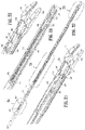
- FIG. 5 is a first side view of the surgical clip applier
- FIG. 6A is a side view, with half of the body removed, of the handle assembly of the surgical clip applier;
- FIG. 6B is an opposite side view relative to FIG. 6A with half of the body removed of the handle assembly of the surgical clip applier;
- FIG. 6C is a perspective view of FIG. 6B with half of the body removed, of the handle assembly of the surgical clip applier;
- FIG. 7 is a perspective view of the handle housing of the clip applier, with parts separated;
- FIG. 7A is a perspective view of the spindle link engaging the spindle
- FIG. 7B is a rear view of the knob with a number of components therein;
- FIG. 7C is a perspective view of the knob exploded from a knob housing
- FIG. 7D is a perspective view of the outer tubular member having a notch
- FIG. 7E is a perspective view of the outer tubular member with a bushing
- FIG. 7F is a rear view of the knob connected to the knob housing and bushing of FIG. 7E ;
- FIG. 7G shows a view of a spindle link connecting to the driver bar
- FIG. 7H shows a cross sectional view of the spindle link connecting to the driver bar along line 7 H- 7 H of FIG. 7G ;
- FIG. 8 is a perspective view of a pawl
- FIG. 9 is a perspective view of a driving member
- FIG. 9A is a perspective view of an actuator plate
- FIG. 9B is a perspective view of a signaling device
- FIG. 9C is a perspective view of a LCD lever
- FIG. 9D is a perspective view of a wishbone link
- FIG. 10 is a perspective view, with parts separated, of the surgical clip applier
- FIG. 10A is a perspective view of a feed bar
- FIG. 10B is a perspective view of a follower and surgical clips
- FIGS. 10C and 10D are opposite perspective views of a trip block
- FIG. 10E is a perspective view of a spindle
- FIG. 10F is an enlarged area of detail of FIG. 10E ;
- FIG. 10G is an enlarged area of detail of FIG. 10E ;
- FIG. 11 is a perspective view of the distal end of the spindle and a driver
- FIG. 12 is a perspective view of a trip lever with the trip lever spring on the spindle
- FIG. 13 is a perspective view of a wedge plate
- FIG. 13A is a perspective view of a “C” shaped window on the wedge plate of FIG. 13 ;
- FIGS. 14 and 15 are opposite perspective views of a filler component
- FIG. 14A is an exploded view of a rotatable member being above a spring bar member in the filler component
- FIG. 16 is a perspective view of the rotation assembly
- FIG. 17 is a perspective view of the overpressure assembly
- FIG. 18 is a perspective view of the spindle and jaw assembly
- FIG. 19 is an enlarged area of detail of the spindle and jaw assembly of FIG. 18 with a feed bar and a pusher connected to the feed bar;
- FIG. 20 is an enlarged area of detail of FIG. 18 ;
- FIG. 21 is an enlarged view of the distal end of the surgical clip applier with outer member removed;
- FIG. 22 is a perspective view of the surgical clip applier with parts removed showing a clip channel member and a follower biasing a number of clips;
- FIG. 23 is an enlarged area at detail of FIG. 22 ;
- FIG. 24 is an enlarged area of detail of FIG. 22 ;
- FIG. 25 is an enlarged area of detail of FIG. 22 ;
- FIG. 26 is a perspective view of the spindle, driver and jaw assembly
- FIG. 27 is an enlarged area of detail of FIG. 26 ;
- FIG. 28 is a perspective view of the cam link and wedge plate assembly
- FIG. 29 is an enlarged area of detail of FIG. 28 ;
- FIG. 30 is an enlarged area of detail of FIG. 29 ;
- FIG. 31 is a perspective view of the filler component and jaw assembly
- FIG. 32 is an enlarged perspective view of the jaw assembly of FIG. 31 ;
- FIGS. 33 and 34 are perspective views of the distal end of the spindle including wedge plate and driver with the wedge plate removed in FIG. 33 ;
- FIG. 35 is a side view, partially shown in section, of the surgical clip applier in a pre-fired condition
- FIG. 36 is in enlarged area of detail of FIG. 35 ;
- FIG. 36A is a first lateral side view of a lockout mechanism
- FIG. 36B is a second opposite lateral side view of FIG. 36A showing the lockout mechanism
- FIG. 36C is another first lateral side view of FIG. 36A showing the lockout mechanism having a ratchet arm;
- FIG. 36D is a cross sectional view of the lockout mechanism along line 36 D- 36 D of FIG. 36C ;
- FIG. 36E is a perspective view showing a first rotatable member, a second rotatable member and a third rotatable member of the lockout mechanism;
- FIG. 36F is a perspective view of a first rotatable member of the lockout mechanism
- FIG. 36G is a perspective view of a third rotatable member of the lockout mechanism.
- FIG. 36H is a perspective view of the second rotatable member of the lockout mechanism having a notch
- FIG. 36I is a perspective view of the second rotatable member of the lockout mechanism being opposite the view of FIG. 36H showing a number of teeth;
- FIG. 37 is an enlarged area of detail of FIG. 35 ;
- FIG. 38 is in enlarged area of detail of FIG. 37 showing the trip lever
- FIG. 39 is an enlarged area of detail of FIG. 37 showing the follower
- FIG. 40 is a side view, shown in section, of the distal end of the surgical clip applier of FIG. 37 having a cam link;
- FIG. 41 is an enlarged area of detail of FIG. 40 ;
- FIG. 41A is a top view of the filler component with the rotatable member engaging the spring bar member;
- FIG. 41B is a cross sectional view of the distal end of the surgical clip applier along line 41 B- 41 B of FIG. 41 ;
- FIG. 42 is a side view, shown in section, of the distal end of the surgical clip applier of FIG. 37 with the feed bar engaging a clip;
- FIG. 42A is an enlarged area of detail of FIG. 42 ;
- FIG. 43 is a perspective view of the wedge plate and jaw assembly
- FIG. 44 is an enlarged area of detail of FIG. 43 ;
- FIG. 45 is a top view of FIG. 43 taken along line 45 - 45 ;
- FIG. 46 is an enlarged area of detail of FIG. 45 showing the jaw and the wedge plate
- FIG. 47 is an enlarged area of detail of FIG. 45 showing the wedge plate and cam link
- FIG. 48 is a side view, shown in section, of the handle housing at the beginning of an initial stroke
- FIG. 49 is an enlarged area of detail of FIG. 48 showing the rack and pawl
- FIG. 49A is an enlarged area of detail of FIG. 48 showing the audible click lever and rib;
- FIG. 50 is an enlarged area of detail of FIG. 48 similar to FIG. 49 ;
- FIG. 50A is an enlarged area of detail of the lockout mechanism of FIG. 48 ;
- FIG. 51 is a side view, shown in section, of the feed bar and trip lever
- FIG. 52 is a side view, shown in section, of the follower
- FIG. 53 is a side view, shown in section, of the endoscopic portion of the surgical clip applier with the spindle and the cam link;
- FIG. 54 is an enlarged area of detail of FIG. 53 illustrating the spindle movement
- FIG. 55 is a top view of the wedge plate and filler component illustrating the movement of the cam link in the cam slot
- FIG. 56 is a side view, shown in section, illustrating the feed bar advancing a clip
- FIG. 57 is a top view of the wedge plate and cam link moving distally and the wedge plate moving relative to the follower with the rotatable member rotating and contacting the spring bar member;
- FIG. 58 is a side view, shown in section, illustrating a clip entering the jaws
- FIG. 59 is a further top view of the cam link and wedge plate movement with the camming feature of the spindle contacting the cam link;
- FIG. 60 is a top view of the wedge plate entering the jaw structure
- FIG. 61 is a perspective view illustrating the rounded distal end of the wedge plate opening the jaw structure for loading
- FIG. 62 is a top view illustrating further advancement of the cam link in the cam slot of the wedge plate
- FIG. 63 is a side view, shown in section, illustrating the trip lever engaged with the feed bar
- FIG. 64 is a side view, shown in section, illustrating a clip that entered the jaws with the feed bar at a most distal position
- FIG. 65 is a top view illustrating the rotatable member in the “C” shaped window of the wedge plate
- FIG. 65A is a bottom view illustrating the rotatable member in the “C” shaped window of the wedge plate deflecting the spring bar member of the filler component;
- FIG. 66 is a side view, shown in section, illustrating the trip lever being cammed out of engagement with the feed bar;
- FIG. 67 is a side view, shown in section, illustrating the retraction of the wedge plate and feed bar
- FIG. 67A is a side view of the handle housing with the trigger at a greater stroke
- FIG. 68 is a side view, shown in section, illustrating further advancement of the spindle
- FIG. 69 is a side view, shown in section, illustrating the retraction of the wedge plate and further advancement of the spindle;
- FIG. 70 is a perspective view of the wedge plate retracting from the jaw structure
- FIG. 71 is a side view, shown in section, with the spindle engaging the driver and a driver lockout member engaging the spindle;
- FIG. 71A is a side view of the handle section with the click lever rotatable to contact the rib in the housing for an audible alarm;
- FIG. 72 is a side view of the handle housing with the trigger at full stroke
- FIG. 73 is a side view, shown in section, of the driver camming the jaws closed about a surgical clip
- FIGS. 74 to 76 are sequential views of the driver camming the jaws closed about a surgical clip
- FIG. 77 is a view, shown in section, of the overpressure mechanism including the impact spring
- FIG. 78 is a perspective view of a surgical clip formed on a vessel
- FIG. 79 is an enlarged area of detail of the pawl resetting
- FIG. 80 is a side view, shown in section, illustrating the spindle retracting
- FIG. 81 is a top view illustrating the rotatable member of the filler component resetting
- FIGS. 82 and 83 are top views illustrating the cam link resetting within the wedge plate
- FIGS. 84 through 86 are side views illustrating the lockout mechanism rotating and the shaft portion of the first rotatable member traversing through the escape notch to engage a corresponding notch in the trigger to prevent the trigger from firing;
- FIG. 87 is an exploded view of another embodiment of the clip applier with a filler component, a wedge plate, a link cam and a spindle;
- FIG. 88A is a top view of the filler component resting on the wedge plate and on the spindle;
- FIG. 88B is a top view of the link cam and the wedge plate resting on the spindle with the filler component removed;
- FIG. 88C is a top view of the link cam and the wedge plate resting on the spindle with the cam slot of the spindle being shown in phantom lines for illustration purposes;
- FIG. 89 is a close up view of the link cam engaging the wedge plate and traversing in the cam slot of the spindle along window 89 of FIG. 88C ;
- FIG. 90 is a perspective view of a first component of an alternative signaling device of the present clip applier.
- FIG. 91 is a top view of the first component of the signaling device of FIG. 90 ;
- FIG. 92 is a side view of the first component
- FIG. 93 is a front view of a channel of the first component
- FIG. 94 is a perspective view of a second component of the alternative signaling device of the present clip applier.
- FIG. 95 is a perspective view of the handle portion of the present clip applier with a rib portion and a lateral click strip;
- FIG. 96 is a perspective view of the handle portion having the assembled signaling device
- FIG. 97 is a perspective view of a clip applied to a vessel
- FIG. 98 is a side view of a spring
- FIG. 99 is a top view of a clip carrying channel according to another embodiment of the present disclosure.
- FIG. 100 shows an enlarged view of the clip carrying channel of FIG. 99 ;
- FIG. 101 illustrates a top view of a lockout bar
- FIG. 102 shows a side view of the lockout bar of FIG. 101 ;
- FIG. 102A is a perspective view of the lockout bar of FIG. 101 ;
- FIG. 103 shows a partially assembled view of the lockout bar of FIGS. 101 and 102 and the spring of FIG. 98 ;
- FIG. 104 is a top view of a clip follower
- FIG. 105 shows a side view of a feed bar having a distal nose and a pair of proximal fins
- FIG. 106 shows a top view of the lockout bar of FIG. 101 in a channel of the clip follower
- FIG. 107 illustrates the lockout bar extending into the distal aperture of the feed bar
- FIG. 108 illustrates another view of the embodiment of the clip applier having the lockout bar extending into the distal aperture of the feed bar;
- FIG. 109 illustrates another view of the embodiment of the clip applier having the cover removed and showing the lockout bar extending into the distal aperture of the feed bar;
- FIG. 110 illustrates another view of the embodiment of the clip applier having the cover and feed bar removed and showing the lockout bar in the feed bar;
- FIG. 111 illustrates another a bottom view of the clip follower with the lockout bar and spring in the channel of the clip follower
- FIG. 112 is a cross sectional view of the clip follower having the lockout bar and the spring in the channel along line 16 - 16 of FIG. 111 ;
- FIG. 113 is a top view of the feed bar having a distal nose and a distal aperture
- FIGS. 114 through 115 are a cross sectional view and bottom view of the spindle of the clip applier having a proximal window
- FIG. 116 is an enlarged view of the window of the spindle of FIG. 114 ;
- FIG. 117 is a side view of the pawl and rack being reset or in the “at rest” or home position
- FIG. 118 is a side view of the pawl and rack being in the intermediate position and configured to prevent retraction of the spindle;
- FIG. 119 is a perspective view of a shear pin according to the present disclosure.
- FIG. 120 is a side cross-sectional view of the clip applier illustrating the rack and pawl locking out the spindle;
- FIG. 121 is a side cross-sectional view of the clip applier illustrating an initial movement of the trigger
- FIG. 122 is a side cross-sectional view of the clip applier illustrating a further movement of the trigger
- FIG. 123 is a side view of a ratchet assembly including an override feature provided in accordance with the present disclosure
- FIG. 124 is a side view of the ratchet assembly of FIG. 123 showing a pawl of the ratchet assembly in an articulated position caused by a rack of the ratchet assembly translating in a distal direction;
- FIG. 125 is a side view of the ratchet assembly of FIG. 123 showing the pawl in an actuated position caused by the rack translating in a proximal direction;
- FIG. 126 is a side view of the ratchet assembly of FIG. 123 showing the pawl having a biasing element coupled thereto;
- FIG. 127 is a side view of another embodiment of a ratchet assembly including an override feature provided in accordance with the present disclosure
- FIG. 128 is a side view of the ratchet assembly of FIG. 127 shown with a pawl of the ratchet assembly removed;
- FIG. 129 is a side view of the ratchet assembly of FIG. 127 showing the pawl in an articulated position caused by a rack of the ratchet assembly translating in a distal direction;
- FIG. 130 is a side view of the ratchet assembly of FIG. 127 showing the pawl in an actuated position caused by the rack translating in a proximal direction.
- a novel endoscopic surgical clip applier having a jaw control mechanism configured to maintain jaws of the surgical clip applier in a spaced apart and stable position during insertion of a surgical clip.
- the novel endoscopic surgical clip applier also has a lockout mechanism.
- the lockout mechanism prevents the surgical clip applier from firing when there are no remaining hemostatic clips.
- the novel endoscopic surgical clip applier also has a signaling device for alerting the surgeon that a clip has been fired. It should be noted that, while the disclosed jaw control mechanism, the driver lockout and the signaling device are all shown and described in an endoscopic surgical clip applier, the disclosed mechanisms are applicable to any surgical clip applier or another instrument having a pair of compressible jaws.
- the surgical clip applier 10 generally has a handle assembly 12 and an endoscopic portion with an elongated tubular member 14 that extends distally from the handle assembly 12 .
- the handle assembly 12 is made from a thermoplastic material and the elongated member is made from a biocompatible material.
- the material may be a stainless steel or in yet another embodiment a titanium material or alloy.
- a pair of jaws 16 is mounted on the distal end of the tubular member 14 .
- the jaws 16 are actuated by a trigger 18 .
- the trigger is movably mounted in handle assembly 12 .
- the jaws 16 are also formed from a suitable biocompatible material such as stainless steel, titanium or a suitable alloy.
- the endoscopic portion also has a knob 20 .
- the knob 20 is rotatably mounted on a distal end of the handle assembly 12 and is connected to the elongated tubular member 14 to provide a three hundred sixty degree rotation of the elongated tubular member 14 and the jaws 16 thereon relative to a longitudinal center axis of the elongated tubular member 14 .
- a significant aspect of the clip applier 10 is that the knob 20 has a suitable configuration so as to be rotated simply using a surgeon's finger, and will be discussed in depth below.
- the endoscopic surgical clip applier 10 has a display 22 .
- the display 22 may be any device known in the art to provide an indication of an event.
- the event may be related to the procedure or the operation of the clip applier 10 .
- the display 22 in a preferred embodiment may be a liquid crystal display.
- the display 22 may be a plasma display, one or more light emitting diodes, a luminescent display, a multi-color display, a digital display, an analog display, a passive display, an active display, a so called “twisted nematic” display, a so called “super twisted nematic” display, a “dual scan” display, a reflective display, a backlit display, an alpha numeric display, a monochrome display, a so called “Low Temperature Polysilicon Thin Film Transistor” or LPTS TFT display, or any other display 22 that indicates a parameter, information or graphics related to the procedure or the clip applier 10 .
- the display is a liquid crystal display 22 or “LCD”.
- the LCD 22 may be a black and white or color display that displays one or more operating parameters of the clip applier 10 to the surgeon.
- FIG. 2A there is shown a front view of the LCD display 22 .
- the display 22 shows a displayed parameter.
- the displayed parameter may be an amount of remaining clips, a number clips that have been used, a position parameter, a surgery time of usage, or any other parameter of the procedure.
- the LCD 22 may display text, a graphic or a combination thereof.
- the LCD 22 may have a tab made from a Mylar or another polymeric insulating material that is disposed between a LCD 22 battery and a contact of the LCD 22 to prevent the battery from being drained during storage.
- the tab may extend out of the clip applier 10 in order to allow for removal of the tab. Once removed, the tab will be pulled out from the clip applier 10 and will permit the battery to contact the electrical contact of the LCD 22 to energize the LCD 22 with power.
- the LCD 22 has a lens that magnifies the display. The lens of the LCD 22 may magnify the display to any desired size in order to allow a surgeon to read the display with ease from a distance.
- the jaws 16 have a channel 24 for receipt of a single surgical clip therein. As is known, a surgical clip may be applied or placed in the channel 24 by a loading structure of the clip applier 10 to apply the hemostatic clip in, for example, a body cavity.
- the handle assembly 12 of the endoscopic surgical clip applier 10 is shown from a first open lateral side of the handle assembly 12 .
- the endoscopic surgical clip applier 10 has the trigger 18 connected to a wishbone link 26 .
- the wishbone link 26 is a member that on one end is connected to the trigger 18 through a trigger slot 28 and on an opposite end has first and a second wishbone shaped members 30 , 32 .
- the first and a second wishbone shaped members 30 , 32 form a space 34 for receipt of a driving member 36 .
- the driving member 36 is a substantially flat member that is longitudinally disposed in the handle assembly 12 as shown and is intended to move one or more driving structures to load, and actuate the jaws 16 to form a fully formed clip, and then reset to an initial position for the next clip application.
- a return spring 38 is disposed to surround the driving member 36 .
- the driving member 36 is connected to a driving mechanism to fire the clip applier 10 and is suitably connected such that after the trigger 18 is actuated and the wishbone link 26 advances the driving member 36 in a longitudinal or distal manner, the return spring 38 will return the driving member 36 and the trigger 18 to its original position for the next clip application.
- the driving member 36 is advantageous.
- the driving member 36 prevents an inadvertent return of the trigger 18 before a full actuation of the open clip applier 10 by impeding movement at an intermediate position once the driving member 36 begins to advance distally.
- the driving member 36 has a rack 40 .
- the rack 40 is disposed on a top side 42 thereof.
- the rack 40 has a number of teeth 44 and the teeth 44 are engaged to engage with another complementary surface to prevent inadvertent return of the trigger 18 and the driving member 18 before a full actuation of the surgical clip applier 10 .
- the surgical clip applier 10 has a pawl 46 with a pawl return spring 48 .
- the pawl 46 is biased with the pawl spring 48 to engage with the teeth 44 of the rack 40 .
- the teeth 44 and the pawl 46 prevent a release of the trigger 18 before a full actuation of the trigger 18 as described herein below.
- the clip applier 10 further has an actuator plate 50 .
- the actuator plate 50 is longitudinally disposed in the handle assembly 12 .
- the actuator plate 50 is disposed below the driving member 36 and is operatively connected to a LCD lever 52 .
- the LCD lever 52 is a suitable structure to be operatively connected to the LCD display 22 .
- Lever 52 moves a suitable mechanism or contact in the LCD display 22 to permit the LCD display 22 to be actuated and thus display one or more operating parameters of the clip applier 10 .
- the actuator plate 50 is connected to the LCD lever 52 to move the corresponding LCD display 22 structure or contact to display an amount of remaining clips that the surgeon has to fire.
- the display may be a number of light emitting diodes, a liquid plasma display, an electronic device or display, a changeable display or a combination thereof.
- the actuator plate 50 further has a signaling device 54 .
- the signaling device 54 is a device that is connected to the actuator plate 50 and that can provide the user with an audible signal that the open clip applier 10 has fired the surgical clip.
- the signaling device 54 emits a sound once the clip applier 10 is fired to provide audible feed back to the surgeon.
- the signaling device 54 may be another electronic device that emits a characteristic sound.
- the signaling device 54 may emit a sound in response to a deflection of the handle or trigger, a compression of a clip, a loading of the clip, a loading of a new clip, an exhaustion of all of the clips, or may emit several different sounds depending on the clip applier 10 event.
- the characteristic sound may be a click, a chirp, a sound, a voice, a recording, a combination of sounds, or any acoustic wave at any decibel level.
- the signaling device 54 may further provide an identification in response to an event of the clip applier 10 .
- the signaling device 54 may emit a sound during normal operation, and then upon the occurrence of the event terminate emitting the sound.
- Various configurations are possible and all within the scope of the present disclosure.
- the clip applier 10 further has a lockout mechanism 56 .
- the lockout mechanism 56 is a structure to prevent the surgeon from dry firing the open clip applier 10 when the amount of clips stored in the clip applier 10 have been exhausted.
- the lockout mechanism 56 engages a complementary structure in the trigger handle A to prevent the trigger 18 from further moving and actuating the wishbone link 26 in a manner described in more detail below.
- the surgical clip applier 10 has the actuator plate 50 that is a substantially “S” shaped member. As best shown in FIGS. 7 and 9A , the actuator plate 50 has a first portion 58 having a first orthogonal shaped window 60 and a second portion 62 with a second orthogonal shaped window 64 .
- the actuator plate 50 On a first end of the actuator plate 50 , the actuator plate 50 has a rounded off or curved portion that forms a pair of tines 66 .
- the opposite second end 68 has a protrusion 70 .
- the protrusion 70 engages a channel 72 on the LCD lever 52 .
- a pin 74 is disposed through the first orthogonal shaped window 60 to connect the actuator plate 50 to the driving member 36 through the wishbone link 26 . In this manner, when the trigger 18 moves the driving member 36 distally, the connecting pin 74 upon being moved through the first window 60 will also move the actuator plate 50 distally in a similar fashion once the connecting pin 74 contacts an outer distal edge 76 of the first orthogonal shaped window 60 .
- the clip applier 10 further has the signaling device 54 with an audible click lever 78 .
- the audible click lever 78 is on an opposite side of the actuator plate 50 and is through the second window 64 .
- the signaling device 54 also has an audible click spring 80 .
- the signaling device 54 also has the audible click lever 78 that will rotate and deflect on a complementary handle surface upon longitudinal distal movement by the actuator plate 50 .
- the actuator plate 50 will move the second window 64 having a lateral side 82 (shown in FIG. 9A ) that will cause a post 77 of the audible click lever 78 ( FIG. 9B ) to deflect and cause the lever 78 to contact a surface rib on the housing. This contact produces an audible alert or an audible signal to the surgeon that the clip applier 10 has fired a surgical clip.
- the clip applier 10 further has the LCD lever 52 (best shown in FIG. 9C ) that is a rotatable member with a first lever portion 84 , an aperture 86 and a curved member 88 having the channel 72 .
- the channel 72 communicates with the protrusion 70 on the actuator plate 50 and has a peg 92 that communicates with the first handle housing portion 94 shown in FIG. 7 .
- the LCD 22 has a LCD unit 96 with an LCD lens 98 and a LCD counter contact plate 100 that is connected to the LCD 22 .
- the LCD counter contact plate 100 upon being actuated will toggle the LCD display 22 from a previous parameter to the current parameter, such as in one embodiment, an amount of remaining clips in the clip applier 10 .
- the clip applier 10 also has the pawl 46 with the pawl spring 48 .
- the pawl 46 has an end that engages with the teeth 44 of the rack 40 .
- the clip applier 10 further has the lockout mechanism 56 having a first rotatable member or shaft 102 with an arm 104 and a pawl 106 connected to the arm 104 .
- the first rotatable member 102 is generally cylindrical shaped and is connected to a complementary surface of the handle through a spring 105 .
- the first rotatable member 102 is a lock out arm
- the lockout mechanism 56 further has a second rotatable member 112 offset from the first rotatable member 102 .
- the second rotatable member 112 in one embodiment is a lockout wheel and has a generally circular configuration with an inner circumference 114 of the lockout wheel 112 having a number of teeth 116 spaced therearound.
- the lockout wheel 112 has a centermost post 118 that is connected through an aperture to a third rotatable member 120 having a first arm 122 connected thereto, and the post 118 is further connected to the handle portion 12 .
- the trigger 18 As the trigger 18 is fired, there exists a relative movement between the first rotatable member 102 connected to the handle portion 12 and the third rotatable member 120 connected to the trigger 18 .
- the lockout wheel 112 is intended to rotate a predetermined amount as the centermost post 118 is connected to the handle portion 12 .
- the pawl 106 of the first rotatable member 102 will advance.
- the lockout wheel 112 has an escape notch 110 that is an orthogonally shaped notch 110 on a radial portion thereof.
- Escape notch 110 permits the pawl 106 of the first rotatable member 102 to traverse from an inner location or the inner circumference 114 of the lockout wheel 112 outward through the escape notch 110 to engage the complementary structure in the trigger shown by reference letter A to prevent the trigger 18 from further moving and actuating the wishbone link 26 .
- the clip applier further has the knob 20 having a shaft assembly 124 .
- a spindle link 126 connects to a spindle 128 shown in FIG. 7A .
- the driver bar 36 connects with the spindle link 126 .
- the spindle link 126 on a proximal side opposite the jaws 16 has spindle link hook 185 .
- the driver bar 36 has an angled hook member 186 .
- the angled hook member 186 is on a distal side 184 of the driver bar 36 .
- the angled hook member 186 of the driver bar 36 mates with the spindle link hook 185 .
- the driving member 36 can thus advance the spindle link 126 in a distal manner.
- an opposite distal end of the spindle link 126 (relative to the spindle link hook 185 ) is connected with a circular boss connection 188 to the spindle 128 .
- the spindle 128 may rotate independently of the spindle link 126 as shown by the reference arrow B.
- FIG. 7B there is shown a cross sectional view of the knob 20 along line 7 B- 7 B of FIG. 5 .
- the knob 20 has a first body half 130 and a second body half 132 connected to one another in an aperture or bore 134 of the knob 20 .
- the knob 20 connects with a knob housing 136 having a planar tapered surface 138 that connects with the knob 20 .
- the knob 20 has the bore 134 disposed therethrough.
- the knob housing 136 further has an outer tubular member 142 with a first slot 144 and a second slot 146 disposed through the tubular member 142 with the outer tubular member 142 having a “C” shaped first aperture 148 and a second “C” aperture 150 on respective opposite laterals sides thereof.
- the knob housing 136 is very advantageous as the knob housing 136 has an elongated cylindrical geometry that is suitable to allow a surgeon to rotate the tubular member 14 simply with one hand by using an index finger to contact a lateral side of the knob 20 and rotate the knob 20 either in a clockwise or a counter clockwise manner. This obviates any two handed operation to rotate the tubular member 14 that is disfavored by some surgeons and provides for a more ergonomic operation or rotation of the tubular member 14 .
- the knob 20 on an inner surface of the bore 134 has a first arm 152 and a second arm 154 that extend opposite an outer surface into the bore 134 for respectively mating with the first “C” shaped aperture 148 and the second “C” shaped aperture 150 of the knob housing 136 .
- the outer tube 14 further has a bushing 156 with a first aperture 158 ′ and a second aperture 160 ′ with a first pin 162 extending through the first aperture 158 ′ and a second pin 164 extending through the second aperture 160 ′.
- the bushing 156 further has a tab 166 that extends from a radial position of the bushing 156 .
- the tab 166 engages with a notch in the knob housing 136 .
- the bushing 156 also has a second tab 166 ′.
- the second tab 166 ′ also engages a notch 168 in the tubular member 14 shown in FIG. 7D for rotation thereof.
- the spindle 128 is mounted for longitudinal movement through the tubular member 14 .
- the pawl 46 is a triangular shaped member with an aperture 169 disposed therethrough.
- the pawl 46 also has a number of angled surfaces 170 , 172 , 174 on a top side 176 and a tooth engaging structure 178 on an opposite bottom side 180 for engaging with the teeth 44 on the rack 40 as shown in the driving member 36 of FIG. 6D .
- the driving member 36 has an aperture 182 for mating with the wishbone link 26 of FIG. 9D and has a first side 181 and an opposite second side 184 with an angled hook member 186 for advancement of the spindle 128 in a distal manner.
- the wishbone link 26 is connected to the driving member 36 through the first longitudinal shaped window 60 of FIG. 9A on the actuator plate 50 by means of the pin 74 .
- the actuator plate 50 with the protrusion 70 connects with the channel 72 in the LCD lever 52 of FIG. 9C and the actuator plate 50 is further connected to the signaling device 54 shown in FIG. 9B .
- the signaling device 54 has an aperture 188 for mating with the handle housing.
- the audible click lever 78 has a bulbous end 190 with a resilient surface 191 such that upon rotation of the click lever 78 the bulbous end 191 can sharply contact another handle surface or rib in order to an acoustic wave to emanate from the handle assembly 12 to signal that the surgical clip has fired.
- the signaling device 54 further has the post 77 is connected through the second window 64 of FIG. 9A and that rotates the lever 54 when the actuator plate 50 moves distally.
- the clip applier 10 has the outer tubular member 14 .
- the outer tubular member 14 is generally a cylindrical member having a first end 192 and a second end 194 .
- the first end 192 is connected through the bore to the spindle link 126 .
- the spindle link 126 is connected to the spindle 128 .
- the outer tube 14 is disposed around the spindle 128 .
- the clip applier 10 has pins 162 , 164 .
- the pins 162 and 164 extend through the lateral sides of the bushing 156 .
- the pins 162 , 164 are biased inward relative to the bushing 156 and contact the outer tubular member 14 .
- the clip applier 10 further has a spring 196 to prevent the bushing 156 from advancing.
- the spring 196 is disposed in the knob housing 136 that connected to the knob 20 .
- the clip applier 10 further has the interlocking spindle link 126 that is disposed through the bore of the elongated tubular member 14 .
- the present clip applier has a number of different assemblies in order to perform a number of different clip applier functions.
- the clip applier 10 has a spindle mechanism 128 in order to traverse through the tubular member 14 to actuate a driving mechanism to close the jaws 16 and form a fully formed clip.
- the clip applier 10 also has a mechanism for a wedging function that is provided to maintain the jaws 16 in a spaced apart condition for loading the jaws 16 that retracts once the jaws 16 are loaded.
- the clip applier 10 also has a feeder function that feeds clips to the jaws 16 .
- the clip applier also has a clip storage function and a clip follower function that biases the stored clips for subsequent loading thereof.
- an actuation mechanism or the spindle 128 shown above the knob 20 in FIG. 10 is provided.
- the spindle 128 is mounted for longitudinal distal and proximal movement through the elongated tubular member 14 .
- the spindle 128 has, on a distal end 204 , a camming mechanism with a driver bar 200 and a slider joint 202 that extends from a distal end 204 of the spindle 128 to selectively engage the camming surfaces and to close the jaws 16 around the surgical clip.
- the spindle 128 further has a latch member 206 on the slider joint 202 and a cam link 208 on the spindle 128 .
- the latch member 206 cams in a direction toward the spindle 128 .
- the latch member 20 cams into a corresponding slot of the spindle 128 .
- the latch member 206 permits the driver bar 200 to move distally.
- the latch member 206 also prevents the driver bar 200 from actuating the jaws 16 when spindle 128 moves distally to reduce a predetermined dwell distance between the spindle 128 and the driver bar 200 .
- the spindle 128 also has a camming feature 210 or bulging edge to move another structure in a perpendicular manner relatively to a longitudinal axis of the spindle 128 during a distal advancement.
- the clip applier 10 retains one or a number of surgical clips 300 for application to the desired tissue.
- the clip applier 10 has an elongated clip channel member 302 for retaining a number of surgical clips 300 shown in an aligned manner above the clip channel member 302 .
- the elongated clip channel member 302 does not move longitudinally relative to the elongated tubular member 14 .
- the clip applier 10 has a follower 306 connected to a follower spring 308 .
- the follower spring 308 urges clips distally in the clip channel member 302 .
- the clip applier 10 also has a channel cover 310 that overlies the clip channel member 302 to retain and guide the follower 306 and the follower spring 308 and the clips 300 distally in the clip channel member 302 .
- the clip applier 10 also has a nose 312 to direct the clips 300 traversing through the clip channel member 302 into the channel 24 between the jaws 16 .
- the clip applier 10 also has a feed bar 400 for feeding clips 300 into the channel 24 between the jaws 16 .
- the feed bar 400 also provides for a relative movement. Referring now to a distal portion of clip channel member 302 , there is shown the feed bar 400 .
- the feed bar 400 at this distal location advances the clips 300 into the channel 24 and between the jaws 16 .
- the feed bar 400 has a pusher spring 402 ( FIG. 10 ).
- the pusher spring 402 biases the feed bar 400 in a longitudinal distal direction.
- the pusher spring 402 is disposed in a complementary location under a notch 404 in a trip block 406 .
- the trip block 406 On a distal side of the trip block 406 , the trip block 406 is adjacent to the clip channel cover member 304 .
- the feed bar 400 is shown above the trip block 406 .
- the feed bar 400 has a hook 408 .
- the hook 408 engages in the notch 404 of the trip block 406 .
- the clip applier 10 further has a guide pin 401 .
- the guide pin 401 is disposed through the pusher spring 402 and necessary to align the pusher spring 402 .
- the hook 408 engages with the guide pin 401 and the pusher spring 402 under the trip block 406 . In this manner, the hook 408 is disposed through the notch 404 to engage the guide pin 401 .
- the pusher spring 402 and guide pin 401 biases the feed bar 400 and permits the feed bar 400 to advance distally. Moreover, the guide pin 401 being disposed through the pusher spring 402 allows for a self-contained assembly.
- the spindle 128 In order for spindle 128 to advance the pusher 400 , the spindle 128 has a trip lever 500 and a biasing spring 502 .
- the trip lever 500 is engaged with the feed bar 400 to advance the surgical clips 300 distally into the clip channel 24 between the jaws 16 .
- the clip applier 100 also has a wedge plate 600 with a wedge plate spring 602 .
- the wedge plate 600 is a flat bar shaped member having a number of orthogonally shaped windows 604 disposed therethrough.
- the wedge plate spring 602 surrounds a tongue 606 in the wedge plate 600 that is in a latch aperture 608 .
- the wedge plate spring 602 permits the wedge plate 600 to be retracted from a distal location to a proximal location after being advanced distally to separate the jaws 16 for clip loading.
- the wedge plate 600 also has a “C” shaped window 610 that is between the windows 604 and the tongue 606 .
- the clip applier 10 also has a filler component 700 .
- the filler component 700 has a rotatable member 702 and a spring bar member 704 .
- the spring bar member 704 is in an aperture 706 disposed in the filler component 700 .
- the rotatable member 702 is capable of a certain particular range of motion and has a first proximal end 708 and a second opposite distal end 710 that is opposite the first end 708 .
- the range of motion of the rotatable member 702 may be any relatively slight or any relatively large range of rotation or movement.
- the present clip applier 10 is not limited in any manner to any specific degree of rotation or any specific manner of movement such as circular, elliptical or even any geometric rotational pattern, origin, axis, coordinates or movement.
- the member 702 may alternatively simply move in any planar or in another irregular manner known in the art.
- Various configurations are possible and within the scope of the present disclosure.
- the clip applier 10 further has the jaws 16 .
- the jaws 16 are made of a first jaw member 16 a and a second jaw member 16 b . Between the first jaw member 16 a and the second jaw member 16 b is the clip channel 24 . As is understood, the jaw members 16 a and 16 b can move inwardly to close and compress to form a fully formed clip in the channel 24 .
- the jaws 16 also have a first raised camming surface 212 and a second raised camming surface 214 on an outer surface thereof. The first raised camming surface 212 and the second raised camming surface 214 permit another driving camming surface selectively engagement therewith for closing and compressing the jaws 16 .
- the feed bar 400 is a longitudinal member having the rectangular shaped window 410 for engagement with the trip lever 500 .
- the feed bar 400 also has the hook 408 disposed on a bottom side 412 of the feed bar.
- the feed bar 400 further has a pusher 414 on a distal end for engaging and manipulating the surgical clips 300 in the clip carrying channel 302 .
- the feed bar 400 cooperates with the follower 306 that slides in the clip carrying channel 302 for pushing and urging the clips 300 distally in the clip carrying channel 302 .
- the trip block 406 both in a first position and in an opposite second position.
- the trip block 406 has the notch 404 therein and also has an angled surface forming a first and second toothed member 420 .
- Each of the first and the second toothed members 420 is for engagement with the corresponding surface of the trip lever 500 that will be discussed herein.
- the notch 404 of the trip block 406 in FIGS. 10C and 10D is for receipt of the hook 408 of the feed bar 400 shown in FIG. 10A .
- the trip block 406 of FIGS. 10C and 10D has the first and second toothed member 420 that engage the trip lever 500 shown in FIG. 10 .
- First and second toothed member 420 disengages the trip lever 500 from the window 410 of FIG. 10A .
- the spindle 128 has a first orthogonal cavity 222 and a second orthogonal shaped cavity 224 for receiving the trip lever 500 , and for receiving the trip lever biasing spring 502 .
- the first orthogonal cavity 222 has a pivoting boss 226 ( FIG. 10F ) to allow the trip lever 500 to pivot from a first position to a second rotatable position.
- the trip lever biasing spring 502 rests in the second cavity 224 .
- the spring 502 shown in FIG. 10 rests therein without any boss or member to connect the biasing spring 502 for ease of manufacture.
- the spindle 128 further has a groove 209 with the camming feature 210 and another cavity 228 to allow the cam link 208 to rest therein and be urged distally.
- the spindle 128 advances distally to engage the drive components of the clip applier 10 as discussed in further detail below.
- the trip lever biasing spring 502 has a first and second bowed ends 504 , 506 that interlock with the second cavity 224 of the spindle 128 as indicated by a dotted line.
- the trip lever biasing spring 502 further has a second member 508 .
- the second member 508 biases outward opposite a normal surface of the spindle 128 .
- the second member 508 contacts the trip lever 500 .
- the trip lever 500 has a C shaped end 510 that engages for rotational movement with the pivoting boss 226 of the spindle 128 and another end 512 that extends above the trip lever biasing spring 502 .
- the trip block 406 has an angled surface or toothed surfaces 420 that can selectively engage the trip lever 500 and disengage the trip lever 500 from the window 410 of the feed bar 400 as discussed previously.
- the spindle 128 has the cam link 208 that is engagable with the wedge plate 600 .
- the cam link 208 has a cam link boss 230 extending therefrom. The cam link 208 is urged distally by the spindle 128 during the stroke.
- the slider joint 202 is connected at a proximal end 248 to the spindle 128 at a channel 250 .
- the slider joint 202 has a “T” shaped end 252 .
- T shaped end 252 is connected to the driver bar 200 .
- the slider joint 202 has a latch member 206 that is a linkage that is disposed to move through an aperture 254 in the slider joint 202 to link with another member and prevent the slider joint 202 from advancing the driver bar 200 , and thus preventing camming surfaces 256 of the driver bar 200 from compressing the jaws 16 during the initial stroke of feeding a clip 300 into the jaws 16 .
- the wedge plate 600 is shown.
- the wedge plate 600 has the wedge plate spring 602 .
- the wedge plate spring 602 provides for a biasing apparatus of the wedge plate 600 .
- the wedge plate 600 is biased by the wedge plate spring 602 .
- the spring 602 surrounds the tongue 606 as indicated by the dotted line.
- the wedge plate 600 also has a “C” shaped aperture or window 610 therethrough.
- the “C” shaped aperture or window 610 selectively engages the rotatable member 702 of the filler component 700 .
- the wedge plate 600 also has a cam slot or groove 612 having a cam surface 614 .
- the cam slot or groove 612 has a predetermined shape that control a motion of the wedge plate 600 .
- the cam slot or groove 612 cooperates with the cam link 208 in the spindle 128 to move the wedge plate 600 distally and to separate the jaws 16 slightly for loading.
- the cam surface 614 also cooperates with the cam link 208 to move the wedge plate 600 proximally within the tubular member 14 so the jaws 16 may compress the clip 300 in the channel 24 once loaded.
- the wedge plate 600 has a rounded distal end 616 for separating the jaws 16 for loading.
- the wedge plate 600 also has a proximal window 622 to limit retraction of the wedge plate 600 .
- the filler component 700 in a first position and in a second opposite position shown in FIG. 15 .
- the filler component 700 has a C shaped end 712 and a rotatable member 702 having an aperture 714 that is connected by a pin 716 in a centermost portion of the filler component 700 .
- the rotatable member 702 connects with a corresponding structure in the wedge plate 600 to control a motion of the wedge plate 600 .
- On an opposite side of the filler component 700 is an aperture 718 .
- the rotatable member 702 has a first end 708 and an opposite second end 710 .
- the first end 708 is biased by contact with the spring bar member 704 that allows biasing action between the spring bar member 704 and the rotatable member 702 .
- the filler component 700 also has (shown in FIG. 15 ) a filler component cam slot 720 .
- the filler component cam slot 720 is configured to receive the boss 230 of the cam link 208 .
- the filler component 700 also has a stop 722 to limit a proximal retraction of the wedge plate 600 and also has a member 724 .
- the member 724 engages the wedge plate tongue 606 and the spring 602 .
- spindle 128 and the related drive components.
- the bushing 156 has the spring 196 being connected thereto as shown in FIG. 17 to allow an over stroke condition of the jaws 16 .
- Spring 196 prevents excessive force from being applied to the jaws 16 .
- the feed bar 400 extends in a downward manner ( FIG. 19 ) so the pusher 414 extends into the clip carrying channel 302 to engage a clip 300 .
- the pusher 414 advances each of the clips 300 in the clip channel member 302 into the channel 24 between the jaws 16 .
- the clip applier 10 has a “C” shaped member 416 that is around the nose 312 that acts as a tissue stop disposed therearound. As discussed above, the nose 312 assists with a single clip being introduced in the channel 24 .
- the clip applier 10 also has a number of T shaped tabs 418 .
- the tabs 418 are in order to hold the clip carrying channel 302 , the channel cover 310 and the nose 312 together as an integral unit.
- the spindle 128 has the trip lever 500 .
- the trip lever 500 extends through window 410 of the feed bar 400 as shown to advance the feed bar 400 distally (through the tubular member 14 ) and to move the pusher 414 distally to introduce the clips 300 into the channel 24 between the jaws 16 .
- FIGS. 21 through 24 shows a number of clips 300 in a clip carrying channel 302 .
- the clip carrying channel 302 has a number of fingers 420 curved therearound ( FIG. 23 ) in order to support and retain the clips 300 in the clip carrying channel 302 .
- FIG. 24 there is shown a partially assembled perspective view of the follower 306 .
- the follower 306 is disposed in the clip carrying channel 302 with the follower spring 308 biasing and advancing the follower 306 in a distal direction.
- the follower spring 308 imparts a force on the clips 300 in the clip channel 302 .
- the clip applier 10 has a number of “T” shaped tabs 418 on the clip channel 302 in order to maintain the assembly together.
- the clip applier 10 has the trip lever 500 on the spindle 128 .
- the trip lever 500 is a T shaped member that is biased to deflect opposite the spindle top side, and biased by a trip lever spring 502 as previously discussed.
- the driver bar 200 is disposed to rest on the wedge plate 600 or jaws 16 in the assembled position and will traverse distally over the first and second raised camming surfaces 212 and 214 to close the jaws 16 and compress the clip 300 in the channel 24 .
- FIGS. 28 through 30 the relative assembled portions of the trip block 406 , the wedge plate 600 , and the filler component 700 will now be described. There is shown the wedge plate 600 disposed on the spindle 128 .
- the clip applier 10 has a stop member 618 to limit movement of the filler component 700 .
- the filler component 700 is disposed beneath the wedge plate 600 in this view.
- the wedge plate 600 has the “C” shaped window 610 with the rotatable member 702 disposed through the “C” shaped window 610 .
- the wedge plate 600 also has the cam slot 612 having the cam surface 614 .
- the cam link 208 is disposed on a top of the wedge plate 600 in this view.
- the cam link 208 has the cam link boss 230 that interfaces with the cam slot 612 of the wedge plate 600 .
- the wedge plate 600 has the wedge plate spring 602 around tongue 606 and the member 724 of the filler component 700 around the tongue 606 . In this manner, when the tongue 606 moves distally relative to the filler component 700 the wedge plate 600 is biased to return proximally.
- the filler component 700 also has the stop 722 in the proximal window 622 of the wedge plate 600 to further limit distal movement of the wedge plate 600 relative to the filler component 700 .
- cam link 208 is also configured to be driven distally in the cam slot 612 . Additionally, the cam link 208 is also configured to be ride in the filler component cam slot 720 shown beneath the wedge plate 600 in this view.
- the cam link boss 230 engages the cam surface 614 of the wedge plate 600 to drive the wedge plate 600 distally.
- the wedge plate 600 will advance distally until it reaches a demarcation line 624 shown in FIG. 30 .
- the cam link boss 231 will engage a disengaging cam surface 726 of the filler component 700 shown in FIG. 30 .
- the disengaging cam surface 726 is a feature in the filler component cam slot 720 . Notably, the disengaging cam surface 726 will cam the cam link boss 231 out of engagement with cam surface 614 of cam slot 612 . At this demarcation point 624 , the wedge plate 600 no longer moves distally.
- the wedge plate 600 lies over the filler component 700 which is positioned on the spindle 128 .
- the jaws 16 have a pair of flexible legs 17 a , 17 b .
- the legs 17 a , 17 b are fixed to a base member 17 c .
- the jaws 16 are located at a distal end relative to the flexible legs 17 a , 17 b .
- a pair of locking arms 19 a , 19 b extends from the base 17 c and terminates in a pair of tabs 21 a , 21 b .
- Tabs 21 a , 21 b engage a pair of holes (not shown) in the elongated outer tube 14 in order to secure the jaws 16 to the elongated tube 14 .
- the filler component 700 is disposed immediately proximal relative to the jaws 16 and does not move relative to the elongated outer tube 14 .
- FIGS. 31 through 33 there is shown a view of the wedge component 600 disposed over the driver bar 200 and resting on the spindle 128 .
- the wedge plate 600 is under the filler component 700 in FIG. 31 .
- the wedge plate 600 being best shown with the jaws removed in FIG. 33 .
- the jaws 16 are configured to receive the rounded distal end 616 of the wedge plate 600 .
- the rounded distal end 616 initially separates the jaws 16 .
- the rounded distal end 616 maintains the jaws 16 in a separate and aligned configuration during insertion of the clip 300 in the channel 24 of the jaws 16 .
- the wedge plate 600 has the rounded distal end 616 that maintains the jaws 16 separated and notably prevents any flexing or torque of the jaws 16 .
- Each of the jaws 16 has a cam feature 23 a , 23 b to guide the rounded distal end 616 of the wedge plate 600 between the jaws 16 as shown in FIG. 32 in an easy and repeatable manner.
- Cam feature 23 a , 23 b are on an inner surface of the jaws 16 as shown and is between the first raised camming surface 212 and the second raised camming surface 214 .
- FIG. 34 there is shown a view of the spindle 128 having the slider joint 202 and the driver bar 200 having the wedge plate 600 removed for illustration purposes.
- the distal end of the driver bar 200 has the driver camming surface 256 .
- the driver camming surface 256 cooperates and moves over the first and the second raised camming surfaces 212 , 214 of the jaws 16 ( FIG. 32 ) in response to the distal movement of the driver bar 200 relative to the jaws 16 .
- latch retractors 158 , 160 extend perpendicular therefrom and are configured to extend through the windows 604 , 604 in the wedge plate 600 shown in FIG. 33 .
- latch retractors 158 , 160 limit a retraction and distal movement of the slider joint 202 relative to the jaws 16 as shown in FIG. 33 .
- latch retractor 158 retracts while latch retractor 160 limits movement.
- latch retractor 160 may retract while the latch retractor 158 limits movement.
- each latch retractor 158 and 160 can switch between functions of limiting movement and retracting.
- more than two latch retractors 158 , 160 may be provided.
- Various configurations are possible and within the scope of the present disclosure.
- the surgical clip applier 10 to crimp a clip 300 around a target tissue, such as a vessel, will now be described.
- a target tissue such as a vessel
- the trigger 18 is shown in an uncompressed state with the driving member 36 in an original position, and biased by the spring 38 .
- FIG. 36A there is shown the lockout mechanism 56 of the surgical clip applier 10 with the lockout mechanism 56 in an original initial position.
- the arm 122 of the third rotatable member 120 has a portion that rests in a channel 121 of the handle assembly 12 as shown in FIG. 36A .
- the third rotatable member 120 mates with the lockout wheel 112 via post 118 .
- the third rotatable member 120 is an indexer wheel.
- the inner circumference 114 of the lockout wheel 112 has a number of teeth 116 and the escape notch 110 .
- the escape notch 110 is disposed at a position around the inner circumference 114 .
- the first rotatable member 102 having the arm 104 and the pawl 106 is offset from the lockout wheel 112 and is disposed so that the pawl 106 selectively engages with the teeth 116 as the clip applier 10 is fired.
- the lockout wheel 112 has a predetermined number of teeth 116 complementary to the number of clips in the clip carrying channel 302 such that when the last clip is fired, the pawl 106 will be aligned with the escape notch 110 allowing the pawl 106 to enter escape notch 110 and be freed from the lockout wheel 112 .
- FIGS. 36 c and 36 d and FIGS.
- the lockout mechanism 56 also has a ratcheting arrangement with a ratchet arm 650 and a number of ratchet teeth 652 .
- the ratchet arm 650 of the third rotatable member 120 is designed to engage with ratchet teeth 652 and rotate the lockout wheel 112 clockwise in response to actuation of the trigger 18 .
- the ratchet arm 650 Upon release of the trigger 18 , the ratchet arm 650 thereafter is rotated in an opposite radial direction to move over each of the ratchet teeth so as to allow the ratchet arm 650 to move counterclockwise to reset to the original position after each clip 300 is fired while not disturbing the radial advancement of the pawl 106 .
- the trip lever 500 in an unfired state is carried by the spindle 128 .
- the trip lever 500 is biased by the trip lever spring 502 .
- the trip lever 500 also is in contact with the proximal window 410 in the feed bar 400 .
- the trip block 406 is in a distal position relative to the trip lever 500 .
- FIG. 39 there is shown the follower 306 biased by the follower spring 408 in order for the clips 300 to be biased in the distal direction.
- FIG. 40 there is shown another cross sectional view of the spindle 128 having the cam link 208 and the wedge plate 600 resting on the spindle 128 .
- the slider joint 202 is disposed under the wedge plate 600 with the latch member 206 disposed in the slider joint 202 .
- the spindle 128 drives the cam link 208 distally an initial distance such that the cam link boss 230 on the cam link 208 engages the cam slot 612 in the wedge plate 600 .
- FIGS. 41 and 41A there is shown another cross sectional view of the outer tube 14 having the filler component 700 .
- the wedge plate 600 is disposed under the filler component 700 with the rotatable member 702 extending therebetween.
- the wedge plate 700 has the spring bar member 704 that is disposed in the aperture 706 .
- the spring bar member 704 biases the rotatable member 702 and can deflect at its free end.
- the rotatable member 702 is disposed distal relative to the camming feature 210 of the spindle 128 that is beneath the filler component 700 shown in dotted lines. Once driven distally, the spindle 128 will advance. The spindle 128 will advance the camming feature 210 .
- the camming feature 210 will be driven distally and will deflect the rotatable member 702 in a clockwise manner.
- FIG. 41B there is shown a cross sectional view of the spindle 128 showing the various components therein along line 41 B- 41 B of FIG. 41 .
- the clip 300 rests in the clip channel 302 and has the feed bar 400 on a top side thereof.
- the wedge plate 600 is disposed underneath the filler component 700 as shown and above the spindle 128 .
- the clip channel cover 310 is disposed above the clip channel 302 .
- the pusher 414 advances each of the clips 300 into the clip channel 24 as shown in FIG. 42A .
- Spindle 128 shown in an unfired state in FIG. 42 .
- the spindle 128 is disposed to connect to the slider joint 202 .
- latch member 206 is mechanically forced to cam down and engages channel 250 of the spindle 128 (which is best shown in FIG. 11 ) in the direction of reference arrow L shown in FIG. 73 .
- This allows the slider joint 202 to move with the driver bar 200 (when driven) distally.
- the driver bar 200 thus can engage the relevant surfaces to close the jaws 16 around the clip 300 disposed in the channel 24 between the jaws 16 .
- FIG. 43 there is shown a perspective view of the wedge plate 600 and the jaws 16 in an original proximal most position.
- the wedge plate 600 has the wedge plate spring 602 in the window 604 around the tongue 606 .
- the wedge plate 600 further has a “C” shaped window 610 to engage the rotatable member 702 .
- the cam link 208 is in a proximal-most position relative to the cam slot 612 .
- the wedge plate 600 also has the rounded distal end 616 engagable with the cam features 23 a , and 23 b to separate the first jaw 16 a and the second jaw 16 b slightly as shown later for loading.
- the cam link 208 is initially disposed in the cam slot 612 in the initial proximal position with the filler component 700 disposed below the cam link 208 in this view.
- the rotatable member 702 has the second end 710 extending through the “C” shaped window 610 .
- the first end 708 of the rotatable member 702 contacts the spring bar member 704 on the filler component 700 that is beneath the wedge plate 600 .
- the trigger 18 is moved through an initial swing as shown by arrow C such that the wishbone link 26 drives the driving member as shown by arrow D.
- the rack 40 on the driving member 36 begins to slide under the pawl 46 as shown by reference arrow E and the pawl 46 rotates to deflect pawl return spring 48 by reference arrow F.
- the signaling device 54 also has an internal rib 2 that is integral with the handle assembly 12 .
- the click lever 78 contacts the click lever spring 80 and upon being recoiled from the spring 80 , the click lever 78 will have the bulbous portion 190 of the click lever 78 contact the internal rib 2 .
- the bulbous portion 190 and the internal rib 2 will resonate thereby providing the surgeon with the audible indication of clip firing.
- the driving member 36 and the rack 40 advance distally the pawl 46 rotates as shown in FIG. 50 . If the trigger 18 were released at this point, the rack 40 would restrain the pawl 46 against any proximal motion and thus prevent release of the trigger and any partial or inadvertent partial actuation of the trigger 18 .
- the lockout wheel 112 of the lockout device 56 also rotates and has the pawl 106 contacting the teeth 116 on the inner circumference 114 of the lockout wheel 112 .
- the pawl 106 will advance from a first tooth space 3 to a next tooth space 5 once clip 300 is fired. If another clip 300 is fired, the pawl 106 will rotate from space 5 to space 7 and continue to advance in a counterclockwise manner until the pawl 106 reaches the escape notch 110 once the last clip 300 has been fired.
- the surgical clip applier 10 is loaded with a number of clips 300 that always exceeds a number of teeth of the lockout wheel 112 to ensure that the surgical clip applier 10 will never dry fire or in other words cannot fire without a clip 300 .
- the spindle 128 moves a predetermined distance.
- the trip lever 500 that this biased by the trip lever spring 502 moves distally and the feed bar 400 is driven distally by the trip lever 500 engaging the feed bar window 410 .
- the follower 306 moves in a distal direction and is urged forward by the follower spring 308 .
- the follower 306 moves each of the clips 300 in a distal manner to be loaded individually into the channel 24 of jaws 16 .
- FIGS. 53 through 55 there is shown a cross sectional view of the various components of the clip applier 10 during the initial stroke with the filler component 700 , wedge plate 600 , and the cam link 208 .
- the boss 230 on the cam link 208 contacts the cam surface 614 on the cam slot 612 of the wedge plate 600 as shown in FIG. 55 .
- the cam link 208 moves distally with the spindle 128 and the cam surface 614 is also urged distally relative to the filler component 700 .
- the pusher 414 urges and advances an individual clip 300 into the channel 24 of the jaws 16 while at an opposite end, the spindle 128 has a suitable geometry such that the spindle 128 has not contacted the driver bar 200 in order to actuate and close the jaws 16 .
- the cam link 208 engages the cam surface 614 of the cam slot 612 to move the wedge plate 600 distally relative to the filler component 700 .
- the “C” shaped window 610 also advances distally, and a lateral surface 625 contacts the second end 710 of the rotatable member 702 .
- the lateral surface 625 of the wedge plate urges the rotatable member 702 to rotate counterclockwise as shown.
- the first end 708 of the rotatable member 702 upon rotation contacts the spring bar member 704 on the filler component 700 and causes the spring bar member 704 of the filler component 700 to deflect.
- the feed bar 400 continues to urge the pusher 414 with the sloping surface to contact a single clip 300 .
- the pusher 414 continues to introduce the clip 300 into the clip channel 24 .
- the wedge plate 600 continues to advance and be driven distally by the cam link 208 urging the cam surface 614 of the cam slot 612 as shown by the reference arrow.
- FIG. 59 shows that the spring bar member 704 after being deflected by the rotatable member 702 recoils in a direction of reference arrow G.
- the recoil moves the rotatable member 702 clockwise so the second end 710 contacts a lateral side 626 of the “C” shaped window 610 as shown by reference arrow H.
- the rotatable member 702 thus conveniently holds the wedge plate 600 in a most distal position and completely controls a position of the wedge plate 600 for loading.
- the cam link 208 at this most distal position of FIG. 59 contacts the camming feature or the disengaging cam surface 726 of the filler component cam slot 720 on the filler component 700 .
- the cam link 208 is now cammed out of engagement with the cam surface 614 and the wedge plate 600 is at its most distal position, and the cam link 208 no longer drives the wedge plate 600 distally.
- the rounded distal end 616 of the wedge plate 600 is now moved in between the camming surface 23 a , 23 b of the first and the second jaw components 16 a , 16 b as shown.
- the rounded distal edge 616 of the wedge plate 600 thus moves the first and second jaw components 16 a , 16 b opposite from one another as shown for gently increasing a size of the channel 24 .
- This additionally restrains each of the jaw members 16 a , 16 b from flexing with regard to one another preventing any torque on the clip 300 as it is being inserted between the jaws 16 as shown by the reference arrows.
- the cam link 208 continued to advance distally in the cam slot 612 while the wedge plate 600 is held by the rotatable member 702 at the second end 710 .
- Rotatable member 702 is held by the spring bar member 704 at the second end 710 between the spring bar member 704 and a lateral wall of the aperture 706 of the filler component 700 .
- the spindle 128 continues to move distally through the stroke, and the trip lever 500 is urged distally with the spindle 128 .
- the camming surface of the feed bar 400 and the trip lever 500 are cammed out of engagement relative to one another.
- the trip lever 500 is cammed out of engagement relative to the window 410 of the feed bar 400 by the toothed member 420 of the trip block 406 . This allows the feed bar 400 to return to a proximal initial position due to the biasing of the feed bar 400 .
- the loading of the clip 300 into the channel 24 is complete and the feed bar 400 is retracted back to an initial position by spring tension.
- the distal portion of the feed bar 400 is shown completing the loading of the clip 300 , and thereafter retracts to an initial proximal location of the clip applier 10 .
- FIGS. 65 and 65A there is shown a bottom view of the wedge plate 600 ( FIG. 65 ), and a top view the filler component 700 ( FIG. 65A ), and the spindle 128 shown in dotted lines.
- the spindle 128 has the camming feature 210 or edge that contacts the second end 710 of the rotatable member 702 as the spindle 128 advances distally.
- the camming feature 210 is advanced distally and deflects the rotatable member 702 in a counterclockwise manner.
- the rotation causes the first end 708 of the rotatable member 702 to likewise deflect the spring bar member 704 of the filler component 700 .
- the rotatable member 702 is no longer holding the wedge plate 600 and the wedge plate 600 is permitted to retract by spring torsion.
- the trip lever 500 is cammed out of engagement with the feed bar window 410 . This permits the feed bar 400 to retract in a proximal direction as shown by arrow J.
- the spindle 128 continues to advance distally during the stroke.
- FIG. 67 there is shown the clip 300 inserted into the channel 24 between the jaws 16 .
- the feed bar 400 now retracts after reaching a most distal position to the next clip 300 and the loading is completed.
- the trip lever 500 is cammed out of engagement with the feed bar 400 and this allows the pusher 414 to retract proximally.
- the feed bar 400 retracts so the nose of the pusher 414 aligns to an initial position for loading the next clip 300 of the number of clips into the channel 24 .
- FIG. 67A there is shown a cross sectional view of the handle assembly 12 .
- the trigger 18 is being fired by the surgeon and typically is grasped and pulled in a direction of reference arrow A.
- the trigger 18 moves the wishbone link 26 that advances to the end of the longitudinal window 60 of the actuator plate 50 .
- the actuator plate 50 driven distally moves the protrusion 70 link to the LCD lever 52 that contacts a suitable LCD contact 100 on the LCD unit 96 to change the display on the LCD display 98 and/or change the displayed parameter.
- the wishbone link 26 also drives the driver member 36 distally to advance the spindle 128 .
- the signaling device 54 is also driven by the actuator plate 50 and has the click lever 78 commencing to rotate to contact the rib 2 of the handle assembly 12 .
- FIG. 69 there is shown a top view of the wedge plate 600 .
- the spindle 128 continues to moves the cam link 208 distally through the cam slot 612 .
- the rotatable member 702 Referring to the “C” shaped window 610 of the wedge plate 600 and the filler component 700 shown above the wedge plate 600 , there is shown the rotatable member 702 .
- the rotatable member 702 has a first proximal end 708 and an opposite second distal end 710 .
- the second distal end 710 of the rotatable member 702 snaps back into the more distal region of the “C” shaped window 610 .
- the spring bar member 704 deflects and returns to an original position.
- the rounded distal end 616 of the wedge plate 600 is retracted from the jaws 16 after loading and moves in a proximal position. As shown in FIG. 70 , the clip 300 rests in the channel 24 of the jaws for application of a compressive force by the jaws.
- the actuator plate 50 in the handle portion 12 continues to move distally urging audible click lever 78 to rotate counterclockwise.
- the audible click lever 78 is then deflected by the click spring 80 .
- the latch member 206 is cammed in a direction toward the spindle 128 so the driver bar 200 can now be engaged and move distally to apply the required compressive force.
- the driver bar 200 is engaged by the spindle 128 .
- the driver bar 200 is driven distally to force jaw legs 16 a and 16 b toward one another so as to compress clip 300 on a vessel.
- FIG. 72 there is shown a cross sectional view of the handle assembly 12 during a full stroke.
- the pawl 46 resets itself so that the instrument can retract and reset when the trigger 18 is released.
- the rack 40 on the driving member 36 is cleared from the pawl in the full stroke position.
- the audible click lever 78 contacts the rib 2 of the housing of the handle 12 by having the bulbous portion 190 sharply contacting the rib 2 making a loud and audible clicking sound.
- the audible click lever 78 is rotated by the actuator plate 50 that is moved distally by the driving member 36 .
- FIG. 73 there is shown the cross sectional view of the endoscopic portion at the full stroke.
- a full stroke of the spindle 128 is required to take a clip 300 from an initial position to a fully inserted position in the jaws 16 .
- the spindle 128 driven to a distal most position moves the driver bar 200 to crimp the clip.
- FIGS. 74 through 76 show the driver bar 200 having the camming surfaces 256 that engage other the first and the second raised camming surfaces 214 , 216 being on each of the jaws 16 a , 16 b .
- the driver bar 200 rides the raised surfaces to close the jaws 16 with the clip 300 in the channel 24 .
- FIG. 76 shows the driver bar 200 with a “T” shaped channel that closes over the camming raised surfaces 212 , 214 of the jaws 16 to apply a compression on the clip 300 in the channel 24 .
- the clip applier 10 has a security mechanism being provided to prevent an over stroke or excessive compression of the clip 300 in the channel 24 by the jaws 16 by squeezing. Such an excessive compression may cause one or more detriments such as an excessive compression of the clip 30 or damage to the driver bar 200 , or the jaws 16 . If the trigger 18 is continued to be squeezed past a full stroke required for a full forming of a clip 300 as shown in FIG. 78 , the impact spring 196 of FIG. 77 compresses in the spaced defined by the knob 20 and the bushing 156 . The impact spring 196 prevents any further distal movement of the spindle 128 by absorbing force beyond what is required to close a clip on a vessel.
- the pawl 46 rotates against the bias of the pawl return spring 48 so the pawl tooth 178 ride along the rack 40 to reset the handle assembly 14 as shown by the reference arrow K.
- the drive member 36 retracts to reset.
- the rack 40 on the drive member 36 moves proximally and back under the pawl 46 .
- the spindle 128 retracts to a proximal position and the latch member 206 is driven upwards opposite the spindle 128 .
- the spindle 128 having the camming feature 210 retracts proximally and contacts the rotatable member 702 that rotates first proximal end 708 of the rotatable member 702 to contact the spring bar member 704 of the filler component 700 .
- the wedge plate 600 does not retract as it has fully retracted already, and the proximal movement by the spindle 128 causes the cam link 208 to return to its original position. In this position, the clip applier 10 is again in an initial position to be re-fired and this to attach to another clip 300 to a vessel.
- the first rotatable member 102 will continue to ratchet through the teeth 116 of the lockout wheel 112 .
- the lockout wheel 112 will progress and radially advance after each of the clips 300 is fired.
- the first rotatable member 102 will rotate until the pawl 106 will reach the escape notch 110 in the lockout wheel 112 .
- the escape notch 110 will then allow the pawl 106 to traverse out from the lockout wheel 112 as shown by arrow K in FIG. 85 .
- the pawl 106 will then mate with a corresponding notch (A) shown in the trigger handle 18 .
- the clip applier 10 will be locked and the pawl 106 will prevent any further firing or driving of the driving member 36 by the trigger 18 .
- the clip applier 10 may be disposed in a suitable receptacle.
- the clip applier 10 is loaded with a number of clips 300 that exceed the number of teeth in the lockout wheel 112 . To this end, the clip applier 10 cannot be dry fired without a clip therein.
- FIGS. 87 through 89 there is shown an alternative embodiment of a number of components of the present clip applier 10 .
- FIG. 87 there is shown an exploded view of a wedge plate 750 , a link cam 752 , a filler component 754 , and a spindle 756 .
- the wedge plate 750 is similar to the embodiment shown previously and has a rounded distal end 758 and is suitably biased at the proximal end to the filler component 754 .
- the rounded distal end 758 preferably moves in a distal manner as discussed to be disposed between the jaws 16 of the clip applier 10 for clip loading.
- the wedge plate 750 further has a link cam notch 760 .
- the link cam notch 760 is in a substantially a mid-portion of the wedge plate 750 .
- the link cam notch 760 is generally orthogonal shaped and is shaped into a lateral side of the wedge plate 750 .
- the link cam notch 760 has a depth that is suitable to extend about to a middle of the wedge plate 750 .
- the link cam notch 760 may have another shape or be circular or curved. Various configurations are possible and within the scope of the present disclosure.
- the link cam notch 760 preferably allows for the link cam 752 to engage and move the wedge plate 750 distally. The distal movement introduces the rounded distal end 758 between the jaws 16 . Distal movement of the spindle 756 disengages the wedge plate 750 at a predetermined line of demarcation.
- the filler component 754 being shown above the wedge plate 750 in FIG. 87 does not move relative to the other components and is intended to remain stationary.
- the filler component 754 has a link cam aperture 762 .
- the link cam aperture 762 is a circular shaped feature that is disposed in the filler component 754 to allow the link cam 752 access.
- the link cam aperture 762 is in a complementary location relative to the link cam notch 760 of the wedge plate 750 . The location allows a portion of the link cam 752 to engage the link cam notch 760 .
- the link cam 752 preferably has two discrete portions.
- the link cam 752 has a first base 764 and a second arm 766 .
- the first base 764 rests and is rotatably mounted in the link cam aperture 762 of the filler component 754 .
- the second arm 766 is connected to the first base 764 .
- the second arm 766 is engagable with the link cam notch 760 of the wedge plate 750 .
- the second arm 766 also has a post 767 that rides in a cam slot 768 of the spindle 756 .
- the link cam 752 preferably has a portion that rotates to move another member a certain fixed distance, and then at the conclusion of the movement to return the member to its initial position.
- the spindle 756 is shown disposed below both the filler component 754 and the wedge plate 750 in FIG. 87 and has a cam slot 768 .
- the cam slot 768 from a distal starting location 770 along the cam slot 768 to a proximal ending location 772 , it is understood that the post 767 of the second arm 766 of the link cam 752 rides in the cam slot 768 and follows the precise path of the cam slot 768 as the spindle 756 advances distally through the stroke.
- the post 767 drives the wedge plate 750 in the cam slot 768 until a certain line of demarcation is reached, then a spring (not shown) or another biasing device of the link cam 752 retracts the post 767 .
- FIG. 88A there is shown the filler component 754 resting on the wedge plate 750 in an assembled state.
- the link cam aperture 762 is shown with the first base portion 764 being in the link cam aperture 762 of the filler component 754 .
- the first base portion 764 can freely move or freely rotate in the link cam aperture 762 of the filler component 754 .
- the first base portion 764 of the link cam 752 can rotate the second arm portion (not shown) underneath the filler component 754 with any desired degree range of rotation and with accuracy, and the clip applier 10 is not specifically limited to any specific amount of rotation.
- FIG. 88B there is shown a view of the wedge plate 750 resting on the spindle 756 with the filler component 754 of FIG. 88A being removed simply for illustration purposes only.
- the link cam 752 has the second arm 766 with the post (not shown) engaged to the link cam notch 760 of the wedge plate 750 .
- the post 767 will urge the wedge plate 750 distally and notably will urge the rounded distal end 758 shown on the distal side between the jaws 16 for loading the clip.
- FIG. 88C there is shown the cam slot 768 of the spindle 756 in broken lines being beneath the wedge plate 750 .
- the cam slot 768 will not disturb an orientation of the link cam 752 .
- the second arm 766 will be cammed counterclockwise, and thus drive the wedge plate 750 by engaging and pushing the link cam notch 760 distally.
- the spindle 756 is continued to be driven distally through the stroke, the post 767 of the second arm 766 of the link cam 752 will traverse past the cam feature 774 .
- the rounded distal end of the wedge plate 758 will be between the jaws 16 for loading.
- FIG. 89 there is shown a close up view of the link cam 754 along window 92 of FIG. 88C in the cam slot 768 of the spindle 756 .
- the link cam 754 will be driven into the proximal most location 770 of the cam slot 768 .
- This proximal most location 770 of the cam slot 768 will permit retraction of the wedge plate 750 once the jaws 16 have been loaded and as the spindle 756 is continued to advance through the stroke for firing.
- the clip applier 10 in this embodiment has the signaling device 54 .
- the signaling device 54 as discussed previously provides an indication to the surgeon that a surgical event has occurred, is occurring or will occur in the future.
- the surgical event may be any event associated with the clip applier 10 , related to the surgical procedure, or both.
- the surgical event may be related to the number of available surgical clips remaining in the clip applier 10 .
- the surgical event may be related to an indication of a time as to when the clip 300 is recommended to be fired.
- the surgical event may be related to or preventing any dry firing of the clip applier and the signaling device 54 may alert the surgeon that the number of surgical clips 300 in the clip applier 10 are too low and that a new clip applier 10 or another device should be procured.
- the surgical event may be other important or convenient parameters of the surgery such as a total time of surgery.
- the signaling device 54 preferably assist the surgeon with feedback of parameters that cannot be readily seen, especially in tandem with using other endoscopic instruments.
- the first component 776 is a cylindrical shaped member.
- the first component 776 preferably has a proximal opening 778 .
- the proximal opening 778 has a channel 780 .
- the channel 780 also has first and second lateral sub channels 780 a , and 780 b that extend into the lateral sides of the first component 776 .
- the proximal opening 778 also has an interior lateral surface 780 c that is disposed to surround an interior of the channel 780 .
- the first component 776 also has a distal side 782 having a camming feature 784 .
- the distal side 782 has the camming feature 784 being a first and a second pointed ends 786 , 788 .
- FIG. 91 there is shown a top view of the first component 776 .
- the first and the second pointed ends 786 and 788 protrude outward and away from the first component 776 at the distal side 782 .
- the first component 776 also has a shelf 787 .
- FIG. 92 there is shown a top view of the first component 776 .
- the first component 776 (in this view) has the first and the second pointed ends 786 , 788 extending outwardly from the distal side 782 .
- FIG. 93 there is shown a view of the proximal opening 778 and channel 780 .
- the channel 780 is suitably sized to permit another member access therein.
- the channel 780 also has the lateral sides with the first lateral sub channel 780 a and the second lateral sub channel 780 b.
- the second component 790 is a lever type structure and is capable of rotation about one rotational axis shown as reference A for illustration purposes.
- the second component 790 has a main post 792 .
- the main post 792 sits on a base portion 794 has a camming surface 796 , and is for insertion in the first component 776 .
- the camming surface 796 has a suitable size to receive one of the first and the second pointed ends 786 and 788 .
- the second component 790 rotates.
- the second component 790 also has another second post 902 and a third post 904 .
- the second post 902 is connected to the main post 792 by a linkage 906 and the third post 904 is connected to the main post 792 by another second linkage 908 .
- the main post 792 extends into the channel 780 of the first component 776 and the first pointed end 786 engages with a first sub recess 910 of the camming surface 796 .
- the first pointed end 786 of the first component 776 will ride in the cam surface 796 causing the first component 776 to move away from the second component 790 .
- the first pointed end 786 will advantageously traverse from the first sub recess 910 to an adjacent second sub recess 912 when the first component 776 is rotated causing the first component 776 to move away from the second component 790 in a direction parallel to the longitudinal axis A.
- the rib portion 914 is a cylindrical shaped feature.
- the rib portion 914 is preferably molded into the handle portion 12 .
- the rib portion 914 has a lateral strip 916 .
- the lateral strip 916 is an orthogonal shaped member that is integrally connected with the cylindrical shaped rib portion 914 .
- FIG. 96 shows an interior view of an opposite lateral side of the handle portion 12 of the clip applier 10 that mates with a portion of the handle portion 12 shown in FIG. 95 .
- FIG. 95 shows a partially assembled view of the signaling device 54 of the clip applier 10 having a spring 901 that rests on the shelf 787 of the first component 776 .
- the lateral strip 916 of the rib portion 916 engages and is disposed through the first cylindrical portion 776 .
- the lateral strip 916 prevents the first component 776 from rotating.
- the lateral strip 916 contacts and prevents the first component from moving due to contact with a lateral side of the first lateral sub channel 780 a.
- the driver bar 918 is connected to actuator plate 920 .
- the actuator plate 920 in this embodiment has a notch 922 on a proximal side thereof.
- the notch 922 engages the second post 902 of the second component 790 .
- the actuator plate 920 having the notch 922 will also rotate the second post 902 of the second component 790 (shown in FIG. 94 ).
- the second component 790 will likewise rotate in a counter clockwise manner thereby rotating the cam notch 796 (shown in FIG. 94 ).
- the cam notch 796 (shown in FIG.
- FIG. 97 illustrates a clip 300 applied to a vessel.
- the clip applier 1010 includes a lockout device.
- the lockout device is located in the handle portion 12 of the instrument 1010 , and locks operation of one or more subassemblies of the instrument 1010 .
- the lockout device is configured to prevent activation of the instrument irrespective of the force applied to the trigger 14 .
- the lockout device in this embodiment prevents the spindle 128 from moving longitudinally.
- the driver bar 200 (or other subcomponents thereof) cannot crimp a clip between the jaws 16 a , 16 b when there are no remaining clips 300 in the clip applier 10 .
- FIG. 98 a number of components of the lockout device will be shown and described.
- FIG. 98 illustrates that the clip applier 1010 has a spring 1100 that is disposed in a predetermined location of a clip carrying channel 1102 ( FIG. 99 ).
- the spring 1100 may be disposed in other areas of the clip applier 1010 , such as in a magazine, or with an embodiment where the clip applier 1010 does not include a clip carrying channel 1102 , the spring 1100 may be disposed or located in other areas.
- the spring 1100 has a first cantilevered free end 1108 and an opposite end 1104 . End 1104 is adapted to receive a lockout bar 1106 (See FIGS. 101 and 102 ).
- the clip carrying channel 1102 is reproduced in FIG. 102 and FIG. 100 in a top view. As can be understood, the distal side 1112 ( FIG. 100 ) of the channel 1102 has the aperture 1110 .
- the clip applier 1010 also has a lockout bar 1106 .
- the lockout bar 1106 is reproduced in FIG. 101 in a top view.
- the lockout bar 1106 includes a first end 1114 , and a second opposite hook end 1116 .
- the lockout bar 1106 is sufficiently sized so as to be wedged between a ceiling and a floor of the clip carrying channel 1102 . In another embodiment, the bar may be wedged between a ceiling and a floor of a clip magazine.
- the groove in the second hook end 1116 is adapted to engage a clip follower 1118 ( FIG. 112 ) of the clip applier 1010 .
- the lockout bar 1106 may be removably or permanently connected to the clip follower 1118 by other methods such as a snap-fit arrangement, a friction-fit arrangement, a screw-fit arrangement, a pin arrangement, or any other arrangement such that first end 1114 may move.
- the lockout bar 1106 is retained between the bottom of the channel cover and the floor 1102 ′ of the clip carrying channel 1102 .
- the lockout bar 1106 rests in a distal slot 1117 formed in the clip follower 1118 (as shown in FIG. 112 ).
- the slot 1117 is shown as generally orthogonal, but may have any similar or different shape known in the art to permit the components to rest in the clip follower 1118 .
- the lockout bar 1106 does not by itself lockout the clip applier 1010 , but instead merely moves upwardly through the clip carrying channel 1102 when there are little or no remaining clips 300 in the clip carrying channel 1102 .
- FIG. 103 illustrates a partially assembled view of the lockout spring 1100 with the lockout bar 1106 .
- clip follower 1118 biases a stack of clips 300 in a clip carrying channel 1102 in a distal manner so the clips 300 may be available to be loaded between the jaws 1016 a , 10166 b in order to be applied to tissue as shown in FIG. 97 .
- the clip follower 1118 has a distal slot 1117 ( FIG. 104 ).
- the lockout bar 1106 is adapted to be received in the slot 1117 and move distally with the clip follower 1118 each time the clip applier instrument 1010 is fired, and the clip follower 1118 is advanced distally.
- FIG. 105 shows that the clip applier 1010 has a feed bar 1120 .
- the feed bar 1120 reciprocates distally, then proximally during each stroke of the firing trigger to load a single clip 300 between the jaws 1016 a , 1016 b ( FIG. 108 ) of the clip applier 1010 .
- the feed bar 1120 has a distal window 1122 .
- the feed bar 1120 is made from a thin metallic material and is moved distally by a trip lever (not shown) and trip lever spring (not shown) as previously discussed with regard to the embodiment above.
- the feed bar 1120 is advantageously disposed above the clip follower 1118 (shown in FIG. 107 ) and the clip carrying channel 1102 (shown in FIG. 109 ).
- the proximal end of the feed bar 1120 has a pair of fins 1119 ( FIG. 105 ).
- the fins 1119 engage a proximal window 1134 of a spindle 1132 of the clip applier 1010 ( FIG. 114 ).
- the proximal end of the feed bar 1120 may have a single fin, or a member which engages window 1134 (or a particular) slot of the spindle 1132 .
- FIG. 107 shows a side view of the components of the clip applier 10 with the clip follower 1118 in its distal most position, and the cover of the clip applier 1010 removed for illustration purposes.
- the feed bar 1120 includes a distal nose 1128 which advances the clips between the jaws (not shown).
- the feed bar 1120 also has a distal window 1122 .
- the clip follower 1118 is positioned beneath the feed bar 1120 and has a slot 1117 .
- the lockout bar 1106 is positioned in the slot 1117 of the clip follower 1118 . As shown in FIG. 107 , in the distal most position, the lockout bar 1106 will deflect upward and engage window 1122 of the feed bar 1120 .
- FIG. 108 shows a top perspective view of the components of the clip applier 1010 .
- the clip applier 1010 has a first jaw 1016 a , a second jaw 1016 b , a stop 1018 connected to a cover 1020 , and a feed bar 1120 .
- Feed bar 1120 has the distal window 1122 .
- the lockout bar 1106 extends into the distal window 1122 when the follower 1118 is in its distal most position, i.e., when there are no remaining clips.
- the lockout bar 1106 extends into the distal window 1122 when the follower 1118 is in its partially distal most position, i.e., when there are little remaining clips such as one, two, or three remaining clips.
- Various arrangements and position of the window 1122 are possible and within the scope of the present disclosure, and it should be appreciated that the window 1122 can be placed at varied locations to lockout the clip applier 1010 with any number of remaining clips in the clip applier 1010 .
- FIG. 109 shows a top perspective view of the components of the clip applier 1010 with the cover 1020 of FIG. 108 removed and showing the nose 1128 of the feed bar 1120 .
- the clip follower 1118 is in the clip carrying channel 1102 and will advance clips in a distal direction until it reaches its distal most position as shown.
- the clip follower 1118 is in the distal most position (as an example for illustration purposes) when there are no remaining clips in the clip carrying channel 1102 or available to be fired by the clip applier 1010 .
- the feed bar 1120 having the distal window 1122 in this distal most position aligns with the lockout bar 1106 .
- the lockout bar 1106 in this distal most position will be deflected upwardly and extend though the distal window 1122 .
- FIG. 110 shows a top perspective view of the components of the clip applier 1010 with the cover 1020 and the feed bar 1120 both removed for illustration purposes to show the relationship between the lockout bar 1106 and the clip follower 1118 .
- the clip carrying channel 1102 has a number of fingers 1103 ′′ on the lateral sides of the clip carrying channel 1102 to maintain the clips (not shown) aligned in the clip carrying channel 1102 .
- Clip follower 1118 is positioned in the clip carrying channel 1102 .
- the lockout bar 1106 is shown positioned in the slot 1117 . It should be appreciated the lockout bar 1106 and the slot 1117 may have different shapes and geometries, and the present disclosure is not limited to any particular shape or geometry. It should further be appreciated the follower 1118 and the lockout bar 1106 may be formed as an integral member with one another. Various configurations are possible and within the scope of the present disclosure.
- FIG. 111 there is shown a bottom view of the clip follower 1118 .
- the clip follower 1118 is shown as having the slot 1117 being generally orthogonal shaped and disposed along a longitudinal axis A of the clip follower 1118 .
- the lockout spring 1100 biases the bar 1106 .
- the lockout spring 1100 has a bulbous member 1108 ′ at end 1108 .
- the bulbous member 1108 ′ of spring 1100 is large enough so as to pass over and avoid being caught in the aperture 1110 in the clip carrying channel 1102 (shown in FIG. 100 ).
- FIG. 112 there is shown a cross sectional view of the clip follower 1118 having the lockout bar 1106 positioned in the slot 1117 of the clip follower 1118 .
- the view is taken along section line 16 - 16 of FIG. 111 .
- Slot 1117 of the clip follower 1118 has a pin 1117 a that is disposed in the groove on the hook portion 1116 of the lockout bar 1106 .
- Pin 1117 a prevents the lockout bar 1106 from being separated from the clip follower 1118 during distal movement.
- lockout spring 1100 Disposed underneath the lockout bar 1106 is the lockout spring 1100 that biases the lockout bar 1106 in a direction opposite the clip carrying channel 1102 as shown in FIG. 111 . Prior to the last clip being applied, the lockout bar 1106 is retained between the bottom surface of the channel cover and the floor 1102 ′ of the clip carrying channel 1102 .
- FIG. 107 illustrates that at the distal most position of the clip follower 1118 , the lockout spring 1100 will move and rotate the free end 1114 of the lockout bar 1106 to a position extending above the clip carrying channel 1102 .
- the free end 1114 of the lockout bar 1106 will rotate upward and escape through the ceiling 1103 ′ of the clip carrying channel 1102 at the distal position of the clip follower 1118 to engage the distal most window 1122 of the feed bar 1120 as shown in FIG. 107 .
- the hook portion 1116 of the lockout bar 1106 will rotate down and engage aperture 1110 in the floor of the clip carrying channel 1102 .
- the distal window 1122 of the feed bar 1120 is shown above immediately adjacent to the nose 1128 of the feed bar 1120 ( FIG. 113 ).
- the free end 1114 of the lockout bar 1106 of FIG. 107 will move above and through the clip carrying channel 1102 and will engage the distal window 1122 of the feed bar 1120 as shown in FIG. 107 .
- a spindle 1132 is shown in FIGS. 114 and 115 .
- the window 1134 is suitably sized and positioned such that the fins 1119 of the feed bar 1120 (shown in FIG. 105 ) simply rest in the window 1134 of the spindle 1132 during normal operation of the clip applier 1010 without effecting the distal or proximal movement of the spindle 1132 .
- the window 1134 is shown in an enlarged view in FIG. 116 .
- the window 1134 has a generally orthogonal shape and the outer lateral surface of the window 1134 will not interfere or contact other components during the normal operation of the clip applier 1010 .
- the feed bar 1120 (shown in FIG. 105 ) is a thin member relative to the spindle 1132 of FIG. 116 .
- the feed bar 1120 is a thin metallic member.
- the feed bar 1120 is a thin thermoplastic member.
- the feed bar 1120 is suitable for reciprocation distally and proximally relative to the spindle 1132 . When the fins 1119 hook the distal edge of window 1134 of spindle 1132 , the feed bar 1120 prevents retraction but not advancement of the spindle 1132 .
- the pawl 1146 in the handle portion ( FIG. 117 ) cannot return to the home or initial position relative to the rack 1140 in the handle portion 12 of the clip applier 1010 . Instead, as shown in FIG. 118 , the pawl 1146 will remain in an intermediate position relative to the rack 1140 .
- the trigger (not shown) is squeezed, pawl 1146 cannot rotate enough to be free of the rack 1140 or move clockwise to reset the pawl 1146 to the home (or at rest position for the next firing of the instrument as shown in FIG. 117 ).
- the pawl 1146 and rack 1136 lockout the trigger 14 from being squeezed and the spindle 1132 cannot move distally to engage the driver bar ( FIGS. 26 and 27 ) and subsequently the clip applier 1010 is unable to close the jaws 1016 a , 1016 b .
- the surgeon will feel a strong tactile feedback from the trigger 14 and resistance that the trigger 14 cannot be compressed toward the handle 12 any further, thus signaling that the clip applier 1010 needs to be disposed/replaced with a new instrument.
- FIG. 119 there is shown a perspective view of a shear pin 1148 for a secondary lockout mechanism 1150 .
- the shear pin 1148 is a generally cylindrical member having a three-part body 1152 defining a first neck portion 1154 and a second neck portion 1156 .
- the first neck portion and the second neck portion 1154 , 1156 respectively have a width that is less than a width of the body 1152 and are configured to engage a linkage 1160 .
- trigger 1156 is connected to linkage 1160 , which, in turn, engages the first and the second neck portions 1154 and 1156 of pin 1148 .
- FIG. 120 there is shown a side cross sectional view of the clip applier 1010 having the rack 1140 and pawl 1146 locking out the spindle 1132 as described above with the secondary lockout mechanism 1150 .
- the trigger 1156 will be prevented from advancing the spindle 1132 distally since the rack 1140 and the pawl 1146 prevent the spindle 1132 from retracting proximally as discussed above.
- the instrument 1010 has a secondary lockout 1150 to prevent the surgeon from placing too much force on the trigger 1156 and the handle 1158 which could possibly overcome or dislodge the engagement between the rack 1140 and the pawl 1146 , and move the spindle 1132 distally.
- FIG. 121 if a force F 1 is placed on the trigger 1156 , the trigger 1156 will move toward the handle 1158 to advance the link 1160 .
- the link 1160 will advance the shear pin 1148 distally to advance the spindle 1132 distally by spindle link 1132 a .
- the engagement between the pawl 1146 and the rack 1140 will prevent the spindle 1132 from moving distally as discussed above.
- FIG. 121 if a force F 1 is placed on the trigger 1156 , the trigger 1156 will move toward the
- the clip applier 10 may include a ratchet assembly having an override feature or device, generally identified by reference numeral 800 .
- Ratchet assembly 800 enables or permits the clinician to open the jaws 16 ( FIG. 1 ) at any point during the firing of a surgical clip.
- the teeth 44 of the rack 40 and the pawl 46 prevent the release of the trigger 18 ( FIG. 1 ) before a full actuation thereof.
- the clinician should wish to abort the firing of a clip, not fully form a clip (e.g., in a case where the clip is being formed over a catheter or other similar device to retain the catheter, rather than clamp the catheter to close it off), or if an obstruction is placed between the jaws 16 that inhibits full formation of a clip, the clinician is inhibited from opening the jaws 16 or returning the trigger 18 to a fully unactuated position. Effectively, the clip applier 10 is locked against further use.
- the ratchet assembly 800 having an override feature, includes a pawl 846 that is substantially similar to pawl 46 , and therefore, for purposes of brevity only the differences therebetween will be described in detail hereinbelow.
- the pawl 846 may define a slot 846 a therethrough configured to receive a corresponding shaft 802 fixedly disposed within the handle assembly 12 . As best illustrated in FIG.
- the pawl 846 defines a generally triangular configuration having a rocker surface 846 b at a first end and a tooth 846 c at a second end opposite the first end, configured to selectively engage the teeth 44 of the rack 40 .
- the slot 846 a of the pawl 846 is oriented such that the slot 846 a extends in a direction from the rocker surface 846 b towards the tooth 846 c and is configured to permit the pawl 846 to rotate about and slide along the shaft 802 .
- the pawl return spring 48 includes a spring constant capable of biasing the pawl 846 towards the rack 40 .
- the pawl return spring 48 exerts a force upon the shaft 802 such that as the rack 40 begins to slide under the pawl 846 ( FIG. 124 ), the pawl 846 deflects the pawl return spring 48 just enough to permit the pawl 846 to rotate, but does not allow the pawl 846 to translate on the shaft 802 and disengage the plurality of teeth 44 of the rack 40 .
- the pawl return spring 48 biases the pawl 846 in a direction such that the shaft 802 is disposed within the slot 846 a adjacent the rocker surface 846 b .
- the force exerted by the pawl return spring 48 on the pawl 846 is great enough such that should the trigger 18 be released by the clinician, the pawl 846 would restrain the rack 40 against any proximal motion or allow the pawl 846 to translate on the shaft 802 , thereby inhibiting the rack 40 from sliding underneath the pawl 846 .
- the clinician may actuate the trigger 18 in an opposite direction (e.g., in a distal direction toward the initial, open position).
- the force applied to the trigger 18 causes the teeth 44 of the rack 40 to exert a corresponding force against the tooth 846 c of the pawl 846 , which is restraining proximal movement of the rack 40 , and therefore exerts a force against the pawl return spring 48 .
- the pawl return spring 48 may not provide sufficient biasing force to enable the pawl 846 to operate normally (e.g., without sliding along the shaft 802 and allowing the tooth 846 c to disengage from the teeth 44 of the rack 40 unintentionally).
- a biasing element 848 FIG. 126
- FIG. 126 may be disposed within the slot 846 a of the pawl 846 .
- the biasing element 848 is interposed between the shaft 802 and a portion of the slot 846 a opposite the tooth 846 c of the pawl 846 such that the biasing element 848 provides additional biasing force to urge the pawl 846 towards the rack 40 .
- the biasing element 848 may be retained within the slot 846 a of the pawl 846 using any suitable means, such as a tab, adhesives, fasteners, or the like.
- the biasing element 848 may be any suitable biasing element capable of being compressed, such as a polymeric spring, gas spring, or the like. It is further contemplated that the biasing element 848 may be any suitable extension spring, such as a coil spring or the like.
- FIGS. 127-130 an alternate embodiment of a ratchet assembly having an override feature or device capable of permitting the clinician to open the jaws 16 at any point during the firing of a surgical clip is illustrated and generally identified by reference numeral 900 .
- the ratchet assembly 900 having an override feature, includes a pawl 946 that is substantially similar to pawl 46 , and therefore, for purposes of brevity only the differences therebetween will be described in detail hereinbelow.
- the pawl 946 defines a generally triangular configuration having a rocker surface 946 a at a first end and a tooth 946 b at a second, opposite end that is configured to selectively engage the teeth 44 of the rack 40 .
- the pawl 946 is rotatably disposed about a shaft 902 that is translatably disposed within a corresponding slot 904 defined within the handle assembly 12 . As best illustrated in FIG.
- the slot 904 is oriented perpendicular to the rack 40 and defines a generally elongated “D” shaped configuration. In this manner, the slot 904 defines an arcuate lower surface 904 a and a planar upper surface 904 b , although other suitable configurations are also contemplated.
- a biasing element 906 is disposed within the slot 904 and is interposed between the planar upper surface 904 b and the shaft 902 such that the shaft 902 is biased towards the arcuate lower surface 904 a of the slot 904 .
- the biasing element 906 may be any suitable biasing element capable of being compressed, such as Bellville, leaf, polymeric spring, gas spring, or the like. In one non-limiting embodiment, the biasing element 906 may be any suitable extension spring.
- the biasing element 906 includes a spring constant capable of biasing the shaft 902 , and thereby the pawl 946 , towards the rack 40 during normal operation. In this manner, the biasing element 906 exerts a force upon the shaft 902 such that as the rack 40 begins to slide under the pawl 946 , the pawl 946 rotates to deflect the pawl return spring 48 , but does not compress the biasing element 906 ( FIG. 129 ). Further, the force exerted by the biasing element 906 upon the shaft 902 is great enough such that should the trigger 18 ( FIG.
- the pawl 946 would restrain the rack 40 against any proximal translation or allow the shaft 902 to translate within the slot 904 and permit the rack 40 from sliding underneath the pawl 946 .
- the pawl return spring 48 provides an additional biasing force against translation of the shaft 902 within the slot 904 . Accordingly, the spring rate of the biasing element 906 , in combination with that of the pawl return spring 48 , is such that the pawl 946 may rotate as described in detail above, but not compress the biasing element 906 during normal operation.
- the clinician may actuate the trigger 18 in an opposite direction (e.g., a distal direction toward the initial, open position and away from the handle assembly 12 ).
- This opposite force applied to the trigger 18 causes the teeth 44 of the rack 40 to exert a corresponding force against the tooth 946 b of the pawl 946 , which is restraining movement of the rack 40 , and therefore exerts a force against the biasing element 906 .
Abstract
Description
Claims (10)
Priority Applications (1)
| Application Number | Priority Date | Filing Date | Title |
|---|---|---|---|
| US16/669,358 US11399846B2 (en) | 2016-11-01 | 2019-10-30 | Endoscopic surgical clip applier |
Applications Claiming Priority (3)
| Application Number | Priority Date | Filing Date | Title |
|---|---|---|---|
| US201662415585P | 2016-11-01 | 2016-11-01 | |
| US15/705,674 US10492795B2 (en) | 2016-11-01 | 2017-09-15 | Endoscopic surgical clip applier |
| US16/669,358 US11399846B2 (en) | 2016-11-01 | 2019-10-30 | Endoscopic surgical clip applier |
Related Parent Applications (1)
| Application Number | Title | Priority Date | Filing Date |
|---|---|---|---|
| US15/705,674 Division US10492795B2 (en) | 2016-11-01 | 2017-09-15 | Endoscopic surgical clip applier |
Publications (2)
| Publication Number | Publication Date |
|---|---|
| US20200060686A1 US20200060686A1 (en) | 2020-02-27 |
| US11399846B2 true US11399846B2 (en) | 2022-08-02 |
Family
ID=62020756
Family Applications (2)
| Application Number | Title | Priority Date | Filing Date |
|---|---|---|---|
| US15/705,674 Active 2038-05-01 US10492795B2 (en) | 2016-11-01 | 2017-09-15 | Endoscopic surgical clip applier |
| US16/669,358 Active 2038-12-07 US11399846B2 (en) | 2016-11-01 | 2019-10-30 | Endoscopic surgical clip applier |
Family Applications Before (1)
| Application Number | Title | Priority Date | Filing Date |
|---|---|---|---|
| US15/705,674 Active 2038-05-01 US10492795B2 (en) | 2016-11-01 | 2017-09-15 | Endoscopic surgical clip applier |
Country Status (1)
| Country | Link |
|---|---|
| US (2) | US10492795B2 (en) |
Cited By (1)
| Publication number | Priority date | Publication date | Assignee | Title |
|---|---|---|---|---|
| US20230115444A1 (en) * | 2020-04-02 | 2023-04-13 | Intuitive Surgical Operations, Inc. | Devices for instrument use recording, devices for recording instrument reprocessing events, and related systems and methods |
Families Citing this family (84)
| Publication number | Priority date | Publication date | Assignee | Title |
|---|---|---|---|---|
| ES2616731T3 (en) | 2004-10-08 | 2017-06-14 | Covidien Lp | Apparatus for applying surgical bras |
| CA2583247C (en) | 2004-10-08 | 2013-06-25 | Tyco Healthcare Group Lp | Endoscopic surgical clip applier |
| EP2314232B1 (en) | 2006-10-17 | 2015-03-25 | Covidien LP | Apparatus for applying surgical clips |
| AU2008230841B2 (en) | 2007-03-26 | 2013-09-12 | Covidien Lp | Endoscopic surgical clip applier |
| CN101677813B (en) | 2007-04-11 | 2012-12-05 | Tyco医疗健康集团 | Surgical clip applier |
| US8465502B2 (en) | 2008-08-25 | 2013-06-18 | Covidien Lp | Surgical clip applier and method of assembly |
| US9358015B2 (en) | 2008-08-29 | 2016-06-07 | Covidien Lp | Endoscopic surgical clip applier with wedge plate |
| US8267944B2 (en) | 2008-08-29 | 2012-09-18 | Tyco Healthcare Group Lp | Endoscopic surgical clip applier with lock out |
| US8409223B2 (en) | 2008-08-29 | 2013-04-02 | Covidien Lp | Endoscopic surgical clip applier with clip retention |
| US8545486B2 (en) | 2009-12-15 | 2013-10-01 | Covidien Lp | Surgical clip applier |
| US8403945B2 (en) | 2010-02-25 | 2013-03-26 | Covidien Lp | Articulating endoscopic surgical clip applier |
| US8968337B2 (en) | 2010-07-28 | 2015-03-03 | Covidien Lp | Articulating clip applier |
| US9186153B2 (en) | 2011-01-31 | 2015-11-17 | Covidien Lp | Locking cam driver and jaw assembly for clip applier |
| US20130131697A1 (en) | 2011-11-21 | 2013-05-23 | Covidien Lp | Surgical clip applier |
| US9364216B2 (en) | 2011-12-29 | 2016-06-14 | Covidien Lp | Surgical clip applier with integrated clip counter |
| US9408610B2 (en) | 2012-05-04 | 2016-08-09 | Covidien Lp | Surgical clip applier with dissector |
| US9532787B2 (en) | 2012-05-31 | 2017-01-03 | Covidien Lp | Endoscopic clip applier |
| US9113892B2 (en) | 2013-01-08 | 2015-08-25 | Covidien Lp | Surgical clip applier |
| US9750500B2 (en) | 2013-01-18 | 2017-09-05 | Covidien Lp | Surgical clip applier |
| US9775624B2 (en) | 2013-08-27 | 2017-10-03 | Covidien Lp | Surgical clip applier |
| US10702278B2 (en) | 2014-12-02 | 2020-07-07 | Covidien Lp | Laparoscopic surgical ligation clip applier |
| US9931124B2 (en) | 2015-01-07 | 2018-04-03 | Covidien Lp | Reposable clip applier |
| EP3244810B1 (en) | 2015-01-15 | 2020-03-18 | Covidien LP | Endoscopic reposable surgical clip applier |
| US10292712B2 (en) | 2015-01-28 | 2019-05-21 | Covidien Lp | Surgical clip applier with integrated cutter |
| US10159491B2 (en) | 2015-03-10 | 2018-12-25 | Covidien Lp | Endoscopic reposable surgical clip applier |
| CN108135622B (en) | 2015-10-10 | 2020-11-27 | 柯惠有限合伙公司 | Endoscopic surgical clip applier |
| WO2017075752A1 (en) | 2015-11-03 | 2017-05-11 | Covidien Lp | Endoscopic surgical clip applier |
| AU2015414615A1 (en) | 2015-11-10 | 2018-04-12 | Covidien Lp | Endoscopic reposable surgical clip applier |
| US10390831B2 (en) | 2015-11-10 | 2019-08-27 | Covidien Lp | Endoscopic reposable surgical clip applier |
| WO2017120734A1 (en) | 2016-01-11 | 2017-07-20 | Covidien Lp | Endoscopic reposable surgical clip applier |
| JP6634521B2 (en) | 2016-01-18 | 2020-01-22 | コヴィディエン リミテッド パートナーシップ | Endoscopic surgical clip applier |
| CA2958160A1 (en) | 2016-02-24 | 2017-08-24 | Covidien Lp | Endoscopic reposable surgical clip applier |
| WO2018027788A1 (en) | 2016-08-11 | 2018-02-15 | Covidien Lp | Endoscopic surgical clip applier and clip applying systems |
| WO2018035796A1 (en) | 2016-08-25 | 2018-03-01 | Covidien Lp | Endoscopic surgical clip applier and clip applying systems |
| US10660651B2 (en) * | 2016-10-31 | 2020-05-26 | Covidien Lp | Endoscopic reposable surgical clip applier |
| US10639044B2 (en) | 2016-10-31 | 2020-05-05 | Covidien Lp | Ligation clip module and clip applier |
| US10492795B2 (en) | 2016-11-01 | 2019-12-03 | Covidien Lp | Endoscopic surgical clip applier |
| US10610236B2 (en) | 2016-11-01 | 2020-04-07 | Covidien Lp | Endoscopic reposable surgical clip applier |
| US10426489B2 (en) | 2016-11-01 | 2019-10-01 | Covidien Lp | Endoscopic reposable surgical clip applier |
| US10709455B2 (en) | 2017-02-02 | 2020-07-14 | Covidien Lp | Endoscopic surgical clip applier |
| US10758244B2 (en) | 2017-02-06 | 2020-09-01 | Covidien Lp | Endoscopic surgical clip applier |
| WO2018141110A1 (en) | 2017-02-06 | 2018-08-09 | Covidien Lp | Surgical clip applier with user feedback feature |
| US10660725B2 (en) | 2017-02-14 | 2020-05-26 | Covidien Lp | Endoscopic surgical clip applier including counter assembly |
| US10603038B2 (en) | 2017-02-22 | 2020-03-31 | Covidien Lp | Surgical clip applier including inserts for jaw assembly |
| US11583291B2 (en) | 2017-02-23 | 2023-02-21 | Covidien Lp | Endoscopic surgical clip applier |
| US10548602B2 (en) | 2017-02-23 | 2020-02-04 | Covidien Lp | Endoscopic surgical clip applier |
| US10675043B2 (en) | 2017-05-04 | 2020-06-09 | Covidien Lp | Reposable multi-fire surgical clip applier |
| US10639032B2 (en) * | 2017-06-30 | 2020-05-05 | Covidien Lp | Endoscopic surgical clip applier including counter assembly |
| US10675112B2 (en) | 2017-08-07 | 2020-06-09 | Covidien Lp | Endoscopic surgical clip applier including counter assembly |
| US10932790B2 (en) | 2017-08-08 | 2021-03-02 | Covidien Lp | Geared actuation mechanism and surgical clip applier including the same |
| US10786262B2 (en) | 2017-08-09 | 2020-09-29 | Covidien Lp | Endoscopic reposable surgical clip applier |
| US10786263B2 (en) | 2017-08-15 | 2020-09-29 | Covidien Lp | Endoscopic reposable surgical clip applier |
| US10835341B2 (en) | 2017-09-12 | 2020-11-17 | Covidien Lp | Endoscopic surgical clip applier and handle assemblies for use therewith |
| US10835260B2 (en) | 2017-09-13 | 2020-11-17 | Covidien Lp | Endoscopic surgical clip applier and handle assemblies for use therewith |
| US10758245B2 (en) | 2017-09-13 | 2020-09-01 | Covidien Lp | Clip counting mechanism for surgical clip applier |
| US10653429B2 (en) | 2017-09-13 | 2020-05-19 | Covidien Lp | Endoscopic surgical clip applier |
| US10945734B2 (en) | 2017-11-03 | 2021-03-16 | Covidien Lp | Rotation knob assemblies and surgical instruments including the same |
| US10932791B2 (en) | 2017-11-03 | 2021-03-02 | Covidien Lp | Reposable multi-fire surgical clip applier |
| US10828036B2 (en) | 2017-11-03 | 2020-11-10 | Covidien Lp | Endoscopic surgical clip applier and handle assemblies for use therewith |
| US11376015B2 (en) | 2017-11-03 | 2022-07-05 | Covidien Lp | Endoscopic surgical clip applier and handle assemblies for use therewith |
| US11116513B2 (en) | 2017-11-03 | 2021-09-14 | Covidien Lp | Modular surgical clip cartridge |
| US10722236B2 (en) | 2017-12-12 | 2020-07-28 | Covidien Lp | Endoscopic reposable surgical clip applier |
| US10743887B2 (en) | 2017-12-13 | 2020-08-18 | Covidien Lp | Reposable multi-fire surgical clip applier |
| US10959737B2 (en) | 2017-12-13 | 2021-03-30 | Covidien Lp | Reposable multi-fire surgical clip applier |
| US10849630B2 (en) | 2017-12-13 | 2020-12-01 | Covidien Lp | Reposable multi-fire surgical clip applier |
| US11051827B2 (en) | 2018-01-16 | 2021-07-06 | Covidien Lp | Endoscopic surgical instrument and handle assemblies for use therewith |
| US10993721B2 (en) | 2018-04-25 | 2021-05-04 | Covidien Lp | Surgical clip applier |
| US10786273B2 (en) | 2018-07-13 | 2020-09-29 | Covidien Lp | Rotation knob assemblies for handle assemblies |
| US11051828B2 (en) | 2018-08-13 | 2021-07-06 | Covidien Lp | Rotation knob assemblies and surgical instruments including same |
| US11344316B2 (en) | 2018-08-13 | 2022-05-31 | Covidien Lp | Elongated assemblies for surgical clip appliers and surgical clip appliers incorporating the same |
| US11246601B2 (en) | 2018-08-13 | 2022-02-15 | Covidien Lp | Elongated assemblies for surgical clip appliers and surgical clip appliers incorporating the same |
| US11278267B2 (en) | 2018-08-13 | 2022-03-22 | Covidien Lp | Latch assemblies and surgical instruments including the same |
| US11219463B2 (en) | 2018-08-13 | 2022-01-11 | Covidien Lp | Bilateral spring for surgical instruments and surgical instruments including the same |
| US11147566B2 (en) | 2018-10-01 | 2021-10-19 | Covidien Lp | Endoscopic surgical clip applier |
| CN109674500B (en) * | 2018-12-25 | 2024-04-02 | 上海逸思医疗科技股份有限公司 | Safety device of surgical instrument |
| US11524398B2 (en) | 2019-03-19 | 2022-12-13 | Covidien Lp | Gear drive mechanisms for surgical instruments |
| JP1660086S (en) * | 2019-10-04 | 2020-05-25 | ||
| JP1660090S (en) * | 2019-10-04 | 2020-05-25 | ||
| JP1660087S (en) * | 2019-10-04 | 2020-05-25 | ||
| JP1660089S (en) * | 2019-10-04 | 2020-05-25 | ||
| US11779340B2 (en) | 2020-01-02 | 2023-10-10 | Covidien Lp | Ligation clip loading device |
| US11723669B2 (en) | 2020-01-08 | 2023-08-15 | Covidien Lp | Clip applier with clip cartridge interface |
| US11660092B2 (en) * | 2020-09-29 | 2023-05-30 | Covidien Lp | Adapter for securing loading units to handle assemblies of surgical stapling instruments |
| JP1702878S (en) * | 2021-04-09 | 2021-12-20 |
Citations (736)
| Publication number | Priority date | Publication date | Assignee | Title |
|---|---|---|---|---|
| US3120230A (en) | 1960-10-24 | 1964-02-04 | Jack H Sanders | Surgical clamp |
| US3363628A (en) | 1964-09-28 | 1968-01-16 | Peter B Samuels | Hemostatic clip |
| US3638847A (en) | 1970-07-06 | 1972-02-01 | United States Surgical Corp | Ratchet-driven cartridge for surgical instruments |
| US3675688A (en) | 1970-04-27 | 1972-07-11 | United States Surgical Corp | Instrument for ligating, suturing and dividing organic tubular structures |
| US3735762A (en) | 1970-04-27 | 1973-05-29 | Us Corp Baltimo E | Instrument for ligating suturing and dividing organic tubular structures |
| US3867944A (en) | 1972-10-27 | 1975-02-25 | Wood Ernest C | Hemostatic clip and applicator therefor |
| EP0000756A1 (en) | 1977-08-05 | 1979-02-21 | Charles H. Klieman | Surgical stapler |
| US4242902A (en) | 1978-05-11 | 1981-01-06 | United States Surgical Corporation | Surgical clip applicator |
| GB2073022A (en) | 1977-10-17 | 1981-10-14 | United States Surgical Corp | Clip stop for surgical clip applying device |
| US4296751A (en) | 1979-08-02 | 1981-10-27 | Blake Joseph W Iii | Surgical device |
| US4372316A (en) | 1979-08-02 | 1983-02-08 | Blake Joseph W Iii | Surgical device |
| US4408603A (en) | 1980-10-24 | 1983-10-11 | Blake Joseph W Iii | Surgical device |
| US4412539A (en) | 1976-10-08 | 1983-11-01 | United States Surgical Corporation | Repeating hemostatic clip applying instruments and multi-clip cartridges therefor |
| US4480641A (en) | 1982-02-05 | 1984-11-06 | Ethicon, Inc. | Tip configuration for a ligating clip applier |
| US4480640A (en) | 1980-04-22 | 1984-11-06 | Senco Products, Inc. | Ligating device |
| US4487205A (en) | 1982-04-26 | 1984-12-11 | Ethicon, Inc. | Non-metallic, bio-compatible hemostatic clips |
| US4487204A (en) | 1981-10-14 | 1984-12-11 | Nomel | Device for applying haemostatic clips |
| US4491133A (en) | 1982-02-05 | 1985-01-01 | Ethicon, Inc. | Folding cartridge for a multiple clip applier |
| US4492232A (en) | 1982-09-30 | 1985-01-08 | United States Surgical Corporation | Surgical clip applying apparatus having fixed jaws |
| US4498476A (en) | 1981-08-27 | 1985-02-12 | Ethicon, Inc. | Non-metallic, bio-compatible hemostatic clips with interlocking latch means |
| US4500024A (en) | 1980-11-19 | 1985-02-19 | Ethicon, Inc. | Multiple clip applier |
| US4509518A (en) | 1982-02-17 | 1985-04-09 | United States Surgical Corporation | Apparatus for applying surgical clips |
| US4512345A (en) | 1982-09-30 | 1985-04-23 | United States Surgical Corporation | Surgical clip applying apparatus, and clips and clip train for use therein |
| US4522207A (en) | 1981-02-06 | 1985-06-11 | Charles H. Klieman | Spring activated hemostatic clip applicator |
| US4532925A (en) | 1979-08-02 | 1985-08-06 | Joseph W. Blake, III | Ligator device |
| US4534351A (en) | 1982-10-20 | 1985-08-13 | Senmed, Inc. | Ligator |
| US4545377A (en) | 1982-09-24 | 1985-10-08 | Ethicon, Inc. | Non-metallic, bio-compatible hemostatic clips (two piece configured to lock tighter the larger the vessel being closed) |
| US4549544A (en) | 1983-10-31 | 1985-10-29 | Senmed, Inc. | Clip stop for a surgical ligating instrument |
| US4556058A (en) | 1983-08-17 | 1985-12-03 | United States Surgical Corporation | Apparatus for ligation and division with fixed jaws |
| US4557263A (en) | 1984-01-23 | 1985-12-10 | United States Surgical Corporation | Apparatus for applying surgical clips |
| US4562839A (en) | 1983-01-06 | 1986-01-07 | Blake Joseph W Iii | Surgical instrument |
| US4572183A (en) | 1984-11-26 | 1986-02-25 | Senmed, Inc. | Positive feed system for a surgical ligating instrument |
| US4576166A (en) | 1981-06-29 | 1986-03-18 | American Cyanamid Company | Surgical ligating instrument |
| US4576165A (en) | 1984-01-23 | 1986-03-18 | United States Surgical Corporation | Surgical ligation and cutting device with safety means |
| US4590937A (en) | 1985-01-07 | 1986-05-27 | American Cyanamid Company | Nonmetallic surgical clip |
| US4598711A (en) | 1984-08-09 | 1986-07-08 | American Cyanamid Company | Surgical instrument |
| US4602631A (en) | 1983-09-08 | 1986-07-29 | Noboru Funatsu | Forceps for clamping surgical clips |
| US4611595A (en) | 1977-08-05 | 1986-09-16 | Charles H. Klieman | Spring activated hemostatic clip applicator |
| US4612932A (en) | 1983-10-04 | 1986-09-23 | Aesculap-Werke Ag Vormals Jetter & Scheerer | Magazine for C-shaped scalp clips |
| US4616650A (en) | 1984-07-27 | 1986-10-14 | United States Surgical Corporation | Apparatus for applying surgical clips |
| US4616651A (en) | 1985-04-15 | 1986-10-14 | Ethicon, Inc. | Surgical clip applier instrument adapter jaws |
| US4637395A (en) | 1983-10-04 | 1987-01-20 | Aesculap-Werke Ag | Applicator for C-shaped scalp clips |
| US4646740A (en) | 1981-02-23 | 1987-03-03 | Edward Weck & Co., Inc. | Automatic hemoclip applier |
| US4647504A (en) | 1984-12-22 | 1987-03-03 | Hoechst Gosei Kabushiki Kaisha | Dispersion of solvent-suspendible pressure sensitive adhesive particles and pressure sensitive adhesive sheet utilizing the properties of the dispersion |
| US4658822A (en) | 1985-12-31 | 1987-04-21 | Kees Jr George | Aneurysm clip |
| US4660558A (en) | 1985-12-31 | 1987-04-28 | Kees Jr George | Aneurysm clip and method of manufacture |
| US4662374A (en) | 1979-08-02 | 1987-05-05 | American Hospital Supply Corp. | Ligator device |
| US4662373A (en) | 1981-06-29 | 1987-05-05 | American Cyanamid Company | Surgical ligating instrument |
| US4671278A (en) | 1985-01-14 | 1987-06-09 | Thomas J. Fogarty | Scalp hemostatic clip and dispenser therefor |
| US4671282A (en) | 1985-10-04 | 1987-06-09 | Tretbar Lawrence L | Clip apparatus |
| US4674504A (en) | 1982-10-06 | 1987-06-23 | Klieman Charles H | Spring activated hemostatic clip applicator |
| US4681107A (en) | 1985-12-31 | 1987-07-21 | Kees Surgical Specialty Co. | Device for holding an aneurysm clip |
| US4696396A (en) | 1985-12-19 | 1987-09-29 | Samuels Peter B | Hemostatic clip cartridge |
| US4702247A (en) | 1985-08-20 | 1987-10-27 | American Hospital Supply Corporation | Ligating clip |
| US4706668A (en) | 1985-09-16 | 1987-11-17 | B & B Tools | Aneurysm clip pliers |
| US4712549A (en) | 1985-07-01 | 1987-12-15 | Edward Weck & Co. | Automatic hemostatic clip applier |
| US4733666A (en) | 1986-01-13 | 1988-03-29 | Texas Tech University Health Sciences Center | Surgical clip for cholangiography |
| US4759364A (en) | 1985-09-19 | 1988-07-26 | Richard Wolf Gmbh | Pincers attachment for a surgical handle to be used in endoscopy |
| US4765335A (en) | 1987-03-16 | 1988-08-23 | Intermar, Inc. | Aneurysm clip |
| US4777949A (en) | 1987-05-08 | 1988-10-18 | Metatech Corporation | Surgical clip for clamping small blood vessels in brain surgery and the like |
| US4796625A (en) | 1982-11-15 | 1989-01-10 | Codman & Shurtleff, Inc. | Aneurysm clip |
| US4799481A (en) | 1987-04-08 | 1989-01-24 | Ethicon, Inc. | Surgical hemostatic clips |
| US4815466A (en) | 1982-09-30 | 1989-03-28 | Perlin Alfred R | Surgical clip |
| US4822348A (en) | 1987-05-13 | 1989-04-18 | Donn Casey | Surgical clips |
| US4821721A (en) | 1985-01-14 | 1989-04-18 | Thomas J. Fogarty | Apparatus and method for applying hemostatic scalp clips |
| US4834096A (en) | 1987-10-26 | 1989-05-30 | Edward Weck Incorporated | Plastic ligating clips |
| US4850355A (en) | 1987-04-06 | 1989-07-25 | Richard-Allan Medical Industries, Inc. | Hemostatic clip applicator for applying multiple hemostatic clips |
| US4854317A (en) | 1987-02-16 | 1989-08-08 | Aesculap-Werke Ag Vormals Jetter & Scheerer | Applicator for C-shaped scalp clips |
| US4856517A (en) | 1986-09-22 | 1989-08-15 | Collins Jason H | Umbilical cord clamp apparatus |
| US4929239A (en) | 1987-02-16 | 1990-05-29 | Aesculap-Werke Ag Vormals Jetter & Scheerer | Device for filling the magazine of a scalp clip applicator with C-shaped scalp clips |
| US4931058A (en) | 1989-08-16 | 1990-06-05 | Applied Vascular Devices, Inc. | Parallel jaw spring clip and method of making same |
| US4957500A (en) | 1988-10-27 | 1990-09-18 | Montefiore Hospital Association Of Western Pennsylvania | Normally closed clamp |
| US4966603A (en) | 1989-07-24 | 1990-10-30 | Rms Company | Aneurysm clip |
| US4967949A (en) | 1986-07-11 | 1990-11-06 | Vastech Medical Products Inc. | Apparatus for effecting occlusion of the vas deferens |
| US4983176A (en) | 1989-03-06 | 1991-01-08 | University Of New Mexico | Deformable plastic surgical clip |
| EP0406724A1 (en) | 1989-07-03 | 1991-01-09 | Edward Weck Incorporated | Automatic hemostatic clip applicator |
| US4988355A (en) | 1990-01-16 | 1991-01-29 | Leveen Eric G | Arterial clamp |
| US5002552A (en) | 1987-11-10 | 1991-03-26 | Donn Casey | Surgical clip |
| US5026379A (en) | 1989-12-05 | 1991-06-25 | Inbae Yoon | Multi-functional instruments and stretchable ligating and occluding devices |
| US5030224A (en) | 1989-09-25 | 1991-07-09 | Pioneering Technologies, Inc. | Coronary artery retraction clip |
| US5030226A (en) | 1988-01-15 | 1991-07-09 | United States Surgical Corporation | Surgical clip applicator |
| US5032127A (en) | 1990-03-07 | 1991-07-16 | Frazee John G | Hemostatic clip and applicator therefor |
| US5035692A (en) | 1990-02-13 | 1991-07-30 | Nicholas Herbert | Hemostasis clip applicator |
| US5047038A (en) | 1985-07-01 | 1991-09-10 | Edward Weck Incorporated | Automatic hemostatic clip applier |
| US5049152A (en) | 1989-03-07 | 1991-09-17 | Richard-Allan Medical Industries | Hemostatic clip applicator |
| US5049153A (en) | 1989-12-26 | 1991-09-17 | Nakao Naomi L | Endoscopic stapling device and method |
| US5053045A (en) | 1988-09-16 | 1991-10-01 | Schmidt Ferenc J | Surgical clip |
| US5059202A (en) | 1988-10-27 | 1991-10-22 | The Montefiore Hospital Association Of Western Pennsylvania | Tendon approximator |
| US5062846A (en) | 1989-03-28 | 1991-11-05 | Edward Weck Incorporated | Penetrating plastic ligating clip |
| US5062563A (en) | 1989-04-10 | 1991-11-05 | United States Surgical Corporation | Fascia stapler |
| US5078731A (en) | 1990-06-05 | 1992-01-07 | Hayhurst John O | Suture clip |
| US5084057A (en) | 1989-07-18 | 1992-01-28 | United States Surgical Corporation | Apparatus and method for applying surgical clips in laparoscopic or endoscopic procedures |
| US5100416A (en) | 1989-10-17 | 1992-03-31 | Edward Weck Incorporated | Ligating clip applying instrument |
| US5100420A (en) | 1989-07-18 | 1992-03-31 | United States Surgical Corporation | Apparatus and method for applying surgical clips in laparoscopic or endoscopic procedures |
| US5104395A (en) | 1989-07-03 | 1992-04-14 | Edward Weck Incorporated | Automatic hemostatic clip applicator |
| US5104394A (en) | 1990-11-05 | 1992-04-14 | Knoepfler Dennis J | Automatic stapler for laparoscopic procedure with selective cutter and suction irrigator |
| US5112343A (en) | 1991-04-05 | 1992-05-12 | Edward Weck Incorporated | Endoscopic clip appliers |
| US5122150A (en) | 1985-03-27 | 1992-06-16 | Puig Ana E | Neurosurgical clip applier |
| US5127915A (en) | 1984-10-29 | 1992-07-07 | Mattson Philip D | Surgical instrument for severing and clamping an umbilical cord |
| US5129885A (en) | 1990-02-13 | 1992-07-14 | United States Surgical Corporation | Safety device for trocars and surgical instruments therefor |
| US5156608A (en) | 1990-07-30 | 1992-10-20 | Hans Troidl | Clip applicator for ligature clips |
| US5160339A (en) | 1991-06-18 | 1992-11-03 | Ethicon, Inc. | Endoscopic suture clip |
| US5163945A (en) | 1991-10-18 | 1992-11-17 | Ethicon, Inc. | Surgical clip applier |
| EP0514139A2 (en) | 1991-05-14 | 1992-11-19 | United States Surgical Corporation | Surgical stapler with spent cartridge sensing and lockout means |
| US5171253A (en) | 1991-03-22 | 1992-12-15 | Klieman Charles H | Velcro-like closure system with absorbable suture materials for absorbable hemostatic clips and surgical strips |
| US5171249A (en) | 1991-04-04 | 1992-12-15 | Ethicon, Inc. | Endoscopic multiple ligating clip applier |
| US5171251A (en) | 1992-03-02 | 1992-12-15 | Ethicon, Inc. | Surgical clip having hole therein and method of anchoring suture |
| US5171247A (en) | 1991-04-04 | 1992-12-15 | Ethicon, Inc. | Endoscopic multiple ligating clip applier with rotating shaft |
| US5171252A (en) | 1991-02-05 | 1992-12-15 | Friedland Thomas W | Surgical fastening clip formed of a shape memory alloy, a method of making such a clip and a method of using such a clip |
| US5171250A (en) | 1987-05-14 | 1992-12-15 | Inbae Yoon | Surgical clips and surgical clip applicator and cutting and transection device |
| US5192288A (en) | 1992-05-26 | 1993-03-09 | Origin Medsystems, Inc. | Surgical clip applier |
| US5197970A (en) | 1988-01-15 | 1993-03-30 | United States Surgical Corporation | Surgical clip applicator |
| US5199566A (en) | 1991-10-18 | 1993-04-06 | Ethicon, Inc. | Surgical clip applier |
| US5201900A (en) | 1992-02-27 | 1993-04-13 | Medical Scientific, Inc. | Bipolar surgical clip |
| US5201746A (en) | 1991-10-16 | 1993-04-13 | United States Surgical Corporation | Surgical hemostatic clip |
| US5207692A (en) | 1990-07-30 | 1993-05-04 | Codman & Shurtleff, Inc. | Surgical clip applier with reciprocating clip sleeve and dual ratchet mechanism |
| US5207691A (en) | 1991-11-01 | 1993-05-04 | Medical Scientific, Inc. | Electrosurgical clip applicator |
| US5217473A (en) | 1989-12-05 | 1993-06-08 | Inbae Yoon | Multi-functional instruments and stretchable ligating and occluding devices |
| US5219353A (en) | 1992-02-28 | 1993-06-15 | Garvey Iii Thomas Q | Surgical endoclip |
| US5246450A (en) | 1992-03-10 | 1993-09-21 | Edward Weck Incorporated | High capacity medical clip feeding and dispensing mechanism |
| US5259366A (en) | 1992-11-03 | 1993-11-09 | Boris Reydel | Method of using a catheter-sleeve assembly for an endoscope |
| US5269792A (en) | 1992-05-26 | 1993-12-14 | Origin Medsystems, Inc. | Surgical clip |
| EP0576835A2 (en) | 1992-06-30 | 1994-01-05 | American Cyanamid Company | Two-part surgical ligation clip and modular ligation clip applicator |
| US5281228A (en) | 1992-11-23 | 1994-01-25 | Fred Wolfson | Umbilical clamp identification device for infants |
| US5282832A (en) | 1992-10-09 | 1994-02-01 | United States Surgical Corporation | Suture clip |
| US5282807A (en) | 1990-11-05 | 1994-02-01 | Knoepfler Dennis J | Automatic stapler for laparoscopic procedure with selective cutter, nontraumatic jaws and suction irrigator |
| US5290299A (en) | 1991-12-11 | 1994-03-01 | Ventritex, Inc. | Double jaw apparatus for attaching implanted materials to body tissue |
| US5289963A (en) | 1991-10-18 | 1994-03-01 | United States Surgical Corporation | Apparatus and method for applying surgical staples to attach an object to body tissue |
| US5300081A (en) | 1992-10-09 | 1994-04-05 | United States Surgical Corporation | Surgical clip applier having clip advancement control |
| US5304183A (en) | 1992-03-23 | 1994-04-19 | Laparomed Corporation | Tethered clamp retractor |
| US5306283A (en) | 1992-06-30 | 1994-04-26 | American Cyanamid Company | Two-part surgical ligation clip |
| US5312426A (en) | 1993-03-12 | 1994-05-17 | Mizuho Ika Kogyo Kabushiki Kaisha | Surgical clip |
| US5330487A (en) | 1992-12-17 | 1994-07-19 | Tfi Acquistion Corp. | Drive mechanism for surgical instruments |
| US5330442A (en) | 1992-10-09 | 1994-07-19 | United States Surgical Corporation | Suture retaining clip |
| US5340360A (en) | 1992-03-06 | 1994-08-23 | Ethicon, Inc. | Ligating clip applier |
| US5342373A (en) | 1992-09-14 | 1994-08-30 | Ethicon, Inc. | Sterile clips and instrument for their placement |
| US5354304A (en) | 1992-10-13 | 1994-10-11 | American Cyanamid Co. | Modular ligation clip applicator |
| US5356064A (en) | 1991-10-18 | 1994-10-18 | United States Surgical Corporation | Apparatus and method for applying surgical staples to attach an object to body tissue |
| US5366458A (en) | 1990-12-13 | 1994-11-22 | United States Surgical Corporation | Latchless surgical clip |
| US5366459A (en) | 1987-05-14 | 1994-11-22 | Inbae Yoon | Surgical clip and clip application procedures |
| US5368600A (en) | 1993-07-23 | 1994-11-29 | Ethicon, Inc. | Steerable bulldog clamp applier |
| US5382253A (en) | 1993-03-05 | 1995-01-17 | Unisurge, Inc. | Clip applier tool |
| US5382254A (en) | 1989-07-18 | 1995-01-17 | United States Surgical Corporation | Actuating handle for surgical instruments |
| US5382255A (en) | 1993-01-08 | 1995-01-17 | United States Surgical Corporation | Apparatus and method for assembly of surgical instruments |
| US5381943A (en) | 1992-10-09 | 1995-01-17 | Ethicon, Inc. | Endoscopic surgical stapling instrument with pivotable and rotatable staple cartridge |
| US5383880A (en) | 1992-01-17 | 1995-01-24 | Ethicon, Inc. | Endoscopic surgical system with sensing means |
| US5383881A (en) | 1989-07-18 | 1995-01-24 | United States Surgical Corporation | Safety device for use with endoscopic instrumentation |
| US5395375A (en) | 1992-11-18 | 1995-03-07 | Symbiosis Corporation | Arthroscopic surgical instruments |
| US5403327A (en) | 1992-12-31 | 1995-04-04 | Pilling Weck Incorporated | Surgical clip applier |
| US5409498A (en) | 1992-11-05 | 1995-04-25 | Ethicon, Inc. | Rotatable articulating endoscopic fastening instrument |
| US5413584A (en) | 1992-05-11 | 1995-05-09 | Ethicon, Inc. | "Omega"-shaped staple for surgical, especially endoscopic, purposes |
| US5425740A (en) | 1994-05-17 | 1995-06-20 | Hutchinson, Jr.; William B. | Endoscopic hernia repair clip and method |
| US5431668A (en) | 1993-04-29 | 1995-07-11 | Ethicon, Inc. | Ligating clip applier |
| US5431667A (en) | 1992-05-26 | 1995-07-11 | Origin Medsystems, Inc. | Gas-sealed instruments for use in laparoscopic surgery |
| US5431669A (en) | 1993-07-16 | 1995-07-11 | Origin Medsystems, Inc. | Surgical clip applier with distal hook |
| US5439468A (en) | 1993-05-07 | 1995-08-08 | Ethicon Endo-Surgery | Surgical clip applier |
| US5441509A (en) | 1992-04-28 | 1995-08-15 | Minnesota Mining And Manufacturing Company | Vessel clips |
| US5447513A (en) | 1992-05-06 | 1995-09-05 | Ethicon, Inc. | Endoscopic ligation and division instrument |
| US5449365A (en) | 1992-09-02 | 1995-09-12 | United States Surgical Corporation | Surgical clamp apparatus |
| US5462555A (en) | 1993-12-30 | 1995-10-31 | United States Surgical Corporation | Umbilical cord clip and applicator |
| US5462558A (en) | 1994-08-29 | 1995-10-31 | United States Surgical Corporation | Suture clip applier |
| US5464416A (en) | 1992-11-10 | 1995-11-07 | Ethicon, Inc. | Ligating clip |
| US5474566A (en) | 1994-05-05 | 1995-12-12 | United States Surgical Corporation | Self-contained powered surgical apparatus |
| US5474572A (en) | 1993-01-07 | 1995-12-12 | Hayhurst; John O. | Clip for suture |
| US5487746A (en) | 1994-11-23 | 1996-01-30 | Yu; George W. | Surgical clip having a longitudinal opening through which clamped tissue protrudes |
| US5487499A (en) | 1993-10-08 | 1996-01-30 | United States Surgical Corporation | Surgical apparatus for applying surgical fasteners including a counter |
| US5501693A (en) | 1994-07-06 | 1996-03-26 | United States Surgical Corporation | Surgical hemostatic clip |
| US5509920A (en) | 1993-04-16 | 1996-04-23 | United States Surgical Corporation | Surgical hemostatic clip |
| US5520701A (en) | 1993-06-16 | 1996-05-28 | Lerch; Karl-Dieter | Set for the treatment of vascular deformations |
| DE29520789U1 (en) | 1995-02-08 | 1996-06-05 | Pier Arnold Dipl Ing Dr Med | Surgical clip applicator |
| US5527320A (en) | 1994-02-10 | 1996-06-18 | Pilling Weck Inc. | Surgical clip applying instrument |
| US5527319A (en) | 1992-02-13 | 1996-06-18 | United States Surgical Corporation | Surgical fastener applying instrument for ligating and dividing tissue |
| US5542949A (en) | 1987-05-14 | 1996-08-06 | Yoon; Inbae | Multifunctional clip applier instrument |
| WO1996024294A1 (en) | 1995-02-08 | 1996-08-15 | Ethicon Endo Surgery Inc | Surgical clip applicator |
| EP0732078A2 (en) | 1995-03-15 | 1996-09-18 | Ethicon Endo-Surgery | Sterile occlusion fasteners and instrument and method for their placement |
| US5569274A (en) | 1993-02-22 | 1996-10-29 | Heartport, Inc. | Endoscopic vascular clamping system and method |
| US5571121A (en) | 1995-03-28 | 1996-11-05 | Heifetz; Milton D. | Atraumatic clamp for temporary occlusion of blood vessels |
| US5575802A (en) | 1994-01-15 | 1996-11-19 | Femcare (Cyprus) Limited | Medical clip |
| US5582615A (en) | 1995-10-30 | 1996-12-10 | Pilling Weck, Incorporated | Handle for surgical clip applicator systems |
| US5582616A (en) | 1994-08-05 | 1996-12-10 | Origin Medsystems, Inc. | Surgical helical fastener with applicator |
| US5584840A (en) | 1995-09-05 | 1996-12-17 | Ramsey; James E. | Umbilical cord cutting and clamping device |
| US5591178A (en) | 1992-10-09 | 1997-01-07 | United States Surgical Corporation | Surgical clip applier |
| US5593421A (en) | 1995-06-06 | 1997-01-14 | Bauer; William | Suture element delivery device and method |
| US5593414A (en) | 1993-08-25 | 1997-01-14 | Apollo Camera, L.L.C. | Method of applying a surgical ligation clip |
| US5601573A (en) | 1994-03-02 | 1997-02-11 | Ethicon Endo-Surgery, Inc. | Sterile occlusion fasteners and instruments and method for their placement |
| US5607436A (en) | 1993-10-08 | 1997-03-04 | United States Surgical Corporation | Apparatus for applying surgical clips |
| US5618306A (en) | 1994-02-14 | 1997-04-08 | Heartport, Inc. | Endoscopic microsurgical instruments and methods |
| US5620452A (en) | 1994-12-22 | 1997-04-15 | Yoon; Inbae | Surgical clip with ductile tissue penetrating members |
| US5626585A (en) | 1994-09-16 | 1997-05-06 | United States Surgical Corporation | Ligating clip advance |
| US5626586A (en) | 1994-05-05 | 1997-05-06 | Wilo-Medizintechnik Lothar Wilberg Gmbh | Pistols for setting surgical clamps |
| US5626587A (en) | 1992-10-09 | 1997-05-06 | Ethicon Endo-Surgery, Inc. | Method for operating a surgical instrument |
| US5643291A (en) | 1994-09-29 | 1997-07-01 | United States Surgical Corporation | Surgical clip applicator |
| US5649937A (en) | 1992-06-04 | 1997-07-22 | Olympus Optical Co., Ltd. | Tissue-fixing surgical device, and method of fixing tissues |
| US5653720A (en) | 1995-07-18 | 1997-08-05 | Applied Medical Resources | Surgical clip and method of assembly |
| US5662679A (en) | 1992-12-21 | 1997-09-02 | Shatzu Health Products, Inc. | Tragus acupressure clip with over-opening prevention and pressure adjustment |
| US5662662A (en) | 1992-10-09 | 1997-09-02 | Ethicon Endo-Surgery, Inc. | Surgical instrument and method |
| US5662676A (en) | 1992-06-24 | 1997-09-02 | K.U. Leuven Research & Development | Instrument set for laparoscopic hysterectomy |
| US5665097A (en) | 1995-04-21 | 1997-09-09 | Baker; John W. | Clip applicator |
| US5676676A (en) | 1995-08-30 | 1997-10-14 | Porter; Wayne | Ligating clip having ramp-shaped vessel-clamping members |
| US5681330A (en) | 1994-03-02 | 1997-10-28 | Ethicon Endo-Surgery, Inc. | Sterile occlusion fasteners and instrument and method for their placement |
| US5683405A (en) | 1995-08-25 | 1997-11-04 | Research Medical Inc. | Vascular occluder |
| US5695505A (en) | 1995-03-09 | 1997-12-09 | Yoon; Inbae | Multifunctional spring clips and cartridges and applicators therefor |
| US5697938A (en) | 1993-09-30 | 1997-12-16 | Price Invena Aps | Device for squeezing and cutting an umbilical cord |
| US5700271A (en) | 1995-10-20 | 1997-12-23 | United States Surgical Corporation | Apparatus for applying surgical clips |
| US5700270A (en) | 1995-10-20 | 1997-12-23 | United States Surgical Corporation | Surgical clip applier |
| US5702048A (en) | 1993-03-18 | 1997-12-30 | Eberlin; Rene | Device for microanatomosis of blood vessels |
| US5709706A (en) | 1994-06-28 | 1998-01-20 | Aesculap Ag | Surgical instrument |
| US5713911A (en) | 1996-10-03 | 1998-02-03 | United States Surgical Corporation | Surgical clip |
| US5713912A (en) | 1995-08-30 | 1998-02-03 | Stress Management, Inc. | Ligating clip having ramp-shaped vessel clamping members and tool for applying same |
| US5720756A (en) | 1992-10-09 | 1998-02-24 | United States Surgical Corporation | Surgical clip applier |
| US5722982A (en) | 1996-09-26 | 1998-03-03 | University Technology Corporation | Strabismus surgery apparatus and method |
| US5725538A (en) | 1992-10-09 | 1998-03-10 | United States Surgical Corporation | Surgical clip applier |
| US5733295A (en) | 1995-09-15 | 1998-03-31 | Aesculap Ag | Surgical vascular clip |
| US5749881A (en) | 1993-10-20 | 1998-05-12 | Applied Medical Resources | Laparoscopic surgical clamp |
| US5766189A (en) | 1996-02-29 | 1998-06-16 | Olympus Optical Co., Ltd. | Clip device |
| US5769857A (en) | 1996-06-11 | 1998-06-23 | Mgf Group Inc. | Ligating clip applier |
| US5772673A (en) | 1996-03-07 | 1998-06-30 | United States Surgical Corporation | Apparatus for applying surgical clips |
| US5776146A (en) | 1993-10-20 | 1998-07-07 | Applied Medical Resources | Laparoscopic surgical clamp |
| US5776147A (en) | 1993-10-20 | 1998-07-07 | Applied Medical Resources Corporation | Laparoscopic surgical clamp |
| US5779720A (en) | 1994-02-11 | 1998-07-14 | Createchnic Ag | One-piece surgical clip |
| US5782844A (en) | 1996-03-05 | 1998-07-21 | Inbae Yoon | Suture spring device applicator |
| US5788698A (en) | 1993-04-19 | 1998-08-04 | Savornin; Claude | Osteosynthesis clip and ancillary material for its emplacement |
| US5792149A (en) | 1996-10-03 | 1998-08-11 | United States Surgical Corporation | Clamp applicator |
| US5797922A (en) | 1996-02-06 | 1998-08-25 | Balagan Medical Inc. | Umbilical cord clamping device |
| US5810853A (en) | 1996-01-16 | 1998-09-22 | Yoon; Inbae | Knotting element for use in suturing anatomical tissue and methods therefor |
| US5817116A (en) | 1996-04-01 | 1998-10-06 | Piolax Inc. | Detaching tool for a tube for medical treatment |
| US5827323A (en) | 1993-07-21 | 1998-10-27 | Charles H. Klieman | Surgical instrument for endoscopic and general surgery |
| US5833695A (en) | 1994-07-13 | 1998-11-10 | Yoon; Inbae | Surgical stapling system and method of applying staples from multiple staple cartridges |
| US5835199A (en) | 1996-05-17 | 1998-11-10 | Coherent Technologies | Fiber-based ladar transceiver for range/doppler imaging with frequency comb generator |
| US5833696A (en) | 1996-10-03 | 1998-11-10 | United States Surgical Corporation | Apparatus for applying surgical clips |
| US5833700A (en) | 1995-03-15 | 1998-11-10 | Ethicon Endo-Surgery, Inc. | Sterile occlusion fasteners and instrument and method for their placement |
| US5843097A (en) | 1996-02-03 | 1998-12-01 | Aesculap Ag | Surgical applicator |
| US5843101A (en) | 1997-05-02 | 1998-12-01 | Fry; William R. | Disposable clip for temporary vessel occulsion |
| US5846255A (en) | 1996-01-31 | 1998-12-08 | Casey Medical Products Limited | Surgical clip |
| US5858018A (en) | 1993-08-25 | 1999-01-12 | Apollo Camera, Llc | Low profile tool for applying spring action ligation clips |
| US5861005A (en) | 1997-02-11 | 1999-01-19 | X-Site, L.L.C. | Arterial stapling device |
| US5868759A (en) | 1997-10-10 | 1999-02-09 | United States Surgical Corporation | Surgical clip applier |
| US5868761A (en) | 1992-10-09 | 1999-02-09 | United States Surgical Corporation | Surgical clip applier |
| US5876410A (en) | 1996-07-22 | 1999-03-02 | Phillip J. Petillo | Hydraulic powered surgical device |
| US5895394A (en) | 1996-09-24 | 1999-04-20 | Aesculap Ag & Co. Kg | Surgical Applicator for U-shaped clips |
| US5897565A (en) | 1995-03-06 | 1999-04-27 | Vance Products Incorporated | Releasable, surgical clamp |
| US5904693A (en) | 1993-04-27 | 1999-05-18 | American Cyanamid Company | Automatic laparoscopic ligation clip applicator |
| US5906625A (en) | 1992-06-04 | 1999-05-25 | Olympus Optical Co., Ltd. | Tissue-fixing surgical instrument, tissue-fixing device, and method of fixing tissue |
| US5913862A (en) | 1997-04-25 | 1999-06-22 | James Ramsey | Umbilical cord cutting and clamping device |
| US5921996A (en) | 1997-05-02 | 1999-07-13 | Cardio Thoracic Systems, Inc. | Surgical clamp applier/remover and detachable clamp |
| US5928251A (en) | 1997-09-18 | 1999-07-27 | United States Surgical Corporation | Occlusion clamp and occlusion clamp applicator |
| US5951574A (en) | 1998-10-23 | 1999-09-14 | Ethicon Endo-Surgery, Inc. | Multiple clip applier having a split feeding mechanism |
| US5972003A (en) | 1997-10-01 | 1999-10-26 | Sherwood Services Ag | Single-free ligation clip module |
| US5976159A (en) | 1995-02-24 | 1999-11-02 | Heartport, Inc. | Surgical clips and methods for tissue approximation |
| US6004335A (en) | 1994-08-02 | 1999-12-21 | Ethicon Endo-Surgery, Inc. | Ultrasonic hemostatic and cutting instrument |
| US6009551A (en) | 1995-05-05 | 1999-12-28 | Trimble Navigation Limited | Optimum utilization of pseudorange and range rate corrections by SATPS receiver |
| US6017358A (en) | 1997-05-01 | 2000-01-25 | Inbae Yoon | Surgical instrument with multiple rotatably mounted offset end effectors |
| US6045560A (en) | 1993-10-06 | 2000-04-04 | United States Surgical Corporation | Surgical stapling apparatus with biocompatible surgical fabric |
| US6059799A (en) | 1998-06-25 | 2000-05-09 | United States Surgical Corporation | Apparatus for applying surgical clips |
| USRE36720E (en) | 1990-12-13 | 2000-05-30 | United States Surgical Corporation | Apparatus and method for applying latchless surgical clips |
| US6099537A (en) | 1996-02-26 | 2000-08-08 | Olympus Optical Co., Ltd. | Medical treatment instrument |
| US6139555A (en) | 1996-04-19 | 2000-10-31 | Applied Medical Resources Corporation | Grasping clip applier |
| US6210418B1 (en) | 1994-05-04 | 2001-04-03 | Karl Storz Gmbh & Co. Kg | Instrument for use in endoscopic surgery |
| US6217590B1 (en) | 1999-01-22 | 2001-04-17 | Scion International, Inc. | Surgical instrument for applying multiple staples and cutting blood vessels and organic structures and method therefor |
| US6228097B1 (en) | 1999-01-22 | 2001-05-08 | Scion International, Inc. | Surgical instrument for clipping and cutting blood vessels and organic structures |
| US6241740B1 (en) | 1998-04-09 | 2001-06-05 | Origin Medsystems, Inc. | System and method of use for ligating and cutting tissue |
| US6258105B1 (en) | 1996-04-18 | 2001-07-10 | Charles C. Hart | Malleable clip applier and method |
| US6261302B1 (en) | 1998-06-26 | 2001-07-17 | Ethicon Endo-Surgery, Inc. | Applier for implantable surgical marker |
| US6273898B1 (en) | 1997-11-26 | 2001-08-14 | Aesculap Ag & Co. Kg | Clip applicator |
| US6277131B1 (en) | 2000-02-15 | 2001-08-21 | Microline, Inc | Ladder-type medical clip feeding mechanism |
| WO2001066001A2 (en) | 2000-03-03 | 2001-09-13 | C.R. Bard, Inc. | Suture clips, delivery devices and methods |
| WO2001067965A1 (en) | 2000-03-17 | 2001-09-20 | Femcare (Cyprus) Limited | Applicator for surgical clips |
| US6306149B1 (en) | 2000-02-15 | 2001-10-23 | Microline, Inc. | Medical clip device with cyclical pusher mechanism |
| US6318619B1 (en) | 2001-03-29 | 2001-11-20 | Yong-Woo Lee | Automatic clip driver |
| US6322571B1 (en) | 1998-06-05 | 2001-11-27 | Brian D. Adams | Apparatus and method for placing sutures in the lacerated end of a tendon and similar body tissues |
| US6350269B1 (en) | 1999-03-01 | 2002-02-26 | Apollo Camera, L.L.C. | Ligation clip and clip applier |
| US6352541B1 (en) | 1997-11-26 | 2002-03-05 | Aesculap Ag & Co. Kg | Magazine for a surgical clip applicator |
| US6391035B1 (en) | 2000-03-24 | 2002-05-21 | Timothy Appleby | Hemostatic clip removal instrument |
| US6423079B1 (en) | 2000-03-07 | 2002-07-23 | Blake, Iii Joseph W | Repeating multi-clip applier |
| US6428548B1 (en) | 1999-11-18 | 2002-08-06 | Russell F. Durgin | Apparatus and method for compressing body tissue |
| US6440144B1 (en) | 2000-04-19 | 2002-08-27 | Karl Storz Gmbh & Co. Kg | Medical instrument having a lockable force transmitting element |
| US6461363B1 (en) | 1997-03-10 | 2002-10-08 | Donald L. Gadberry | Surgical clips and clamps |
| US6464710B1 (en) | 1995-03-06 | 2002-10-15 | Cook Urological Incorporated | Releasable, surgical clamp |
| US6494886B1 (en) | 2000-06-22 | 2002-12-17 | Granit Medical Innovation, Inc. | Off-set clamp mechanism and associated method for minimally invasive surgery |
| JP2003033361A (en) | 2001-07-24 | 2003-02-04 | Inprest Co Ltd | Surgical clip feeding device |
| US6517536B2 (en) | 2000-04-27 | 2003-02-11 | Atricure, Inc. | Transmural ablation device and method |
| US6520972B2 (en) | 2000-02-04 | 2003-02-18 | Stephen F. Peters | Surgical clip applier |
| US6537289B1 (en) | 1999-11-29 | 2003-03-25 | General Surgical Innovations, Inc. | Blood vessel clip applicator |
| US6551333B2 (en) | 2000-10-19 | 2003-04-22 | Ethicon Endo-Surgery, Inc. | Method for attaching hernia mesh |
| US6569171B2 (en) | 2001-02-28 | 2003-05-27 | Microline, Inc. | Safety locking mechanism for a medical clip device |
| US6579304B1 (en) | 1997-02-03 | 2003-06-17 | Applied Medical Resources Corporation | Surgical clamp with improved traction |
| US6599298B1 (en) | 2000-10-23 | 2003-07-29 | Vitalitec International, S.A. | Automatic surgical clip applier |
| US6602252B2 (en) | 2002-01-03 | 2003-08-05 | Starion Instruments Corporation | Combined dissecting, cauterizing, and stapling device |
| US6613060B2 (en) | 1997-06-02 | 2003-09-02 | Scimed Life Systems, Inc. | Textured ligating band |
| US6626916B1 (en) | 1998-12-31 | 2003-09-30 | Teresa T. Yeung | Tissue fastening devices and methods for sustained holding strength |
| US6626922B1 (en) | 1997-02-03 | 2003-09-30 | Applied Medical Resources Corporation | Surgical instruments with improved traction |
| US20030208231A1 (en) | 1999-05-11 | 2003-11-06 | Williamson Warren P. | Surgical clamp devices and methods especially useful in cardiac surgery |
| US6648898B1 (en) | 2000-03-02 | 2003-11-18 | Cardiothoracic Systems, Inc. | Clip applying apparatuses and methods for vascular ligation |
| US6652538B2 (en) | 1998-07-10 | 2003-11-25 | General Surgical Innovations, Inc. | Apparatus and method for surgical fastening |
| US6656193B2 (en) | 2001-05-07 | 2003-12-02 | Ethicon Endo-Surgery, Inc. | Device for attachment of buttress material to a surgical fastening device |
| US20030229360A1 (en) | 2002-05-31 | 2003-12-11 | Gayton John F. | Tissue fastener having a shaft with a reduced cross-section |
| US6676659B2 (en) | 2000-08-14 | 2004-01-13 | Scimed Life Systems, Inc. | Steerable sphincterotome and methods for cannulation, papillotomy and sphincterotomy |
| US6679894B2 (en) | 2001-10-24 | 2004-01-20 | Scimed Life Systems, Inc. | Multiple hemoclip system for an endoscope |
| USRE38445E1 (en) | 1994-05-05 | 2004-02-24 | Tyco Healthcare Group, Lp | Pistols for setting surgical clamps |
| US6706057B1 (en) | 1999-11-18 | 2004-03-16 | Gianfranco Bidoia | Compression suture device |
| US6716226B2 (en) | 2001-06-25 | 2004-04-06 | Inscope Development, Llc | Surgical clip |
| US6723109B2 (en) | 2001-02-07 | 2004-04-20 | Karl Storz Endoscopy-America, Inc. | Deployable surgical clamp with delivery/retrieval device and actuator |
| US6743241B2 (en) | 2002-03-01 | 2004-06-01 | Intellimed Surgical Solutions Llc | Laparoscopic port site fascial closure device |
| US20040138681A1 (en) | 2001-04-25 | 2004-07-15 | Arnold Pier | Surgical-clip applicator |
| US6773438B1 (en) | 2000-10-19 | 2004-08-10 | Ethicon Endo-Surgery | Surgical instrument having a rotary lockout mechanism |
| US6773440B2 (en) | 2002-07-02 | 2004-08-10 | Satiety, Inc. | Method and device for use in tissue approximation and fixation |
| US6776784B2 (en) | 2001-09-06 | 2004-08-17 | Core Medical, Inc. | Clip apparatus for closing septal defects and methods of use |
| US6776783B1 (en) | 1999-01-08 | 2004-08-17 | Cardiothoracic Systems, Inc. | Surgical clips and apparatus and method for clip placement |
| US6780195B2 (en) | 1999-11-14 | 2004-08-24 | Starburst Technologies Limited | Device for clamping and cutting a flexible deformable tube |
| US20040167545A1 (en) | 2000-08-18 | 2004-08-26 | Sadler Kenneth George | Applicator for surgical clips |
| US20040176784A1 (en) | 2002-07-19 | 2004-09-09 | Olympus Corporation | Clip manipulating device |
| US20040176783A1 (en) | 2002-12-16 | 2004-09-09 | Edrich Vascular Devices, Inc. | Vascular suturing clip |
| US6793663B2 (en) | 1999-07-30 | 2004-09-21 | Forschungszentrum Karlsruhe Gmbh | Surgical applicator tip for delivering clips of clamps |
| US6793664B2 (en) | 2000-06-19 | 2004-09-21 | Image-Guided Neurologics | System and method of minimally-invasive exovascular aneurysm treatment |
| US20040193213A1 (en) | 2003-03-11 | 2004-09-30 | Ernest Aranyi | Clip applying apparatus with curved jaws, and clip |
| US6802848B2 (en) | 2002-03-12 | 2004-10-12 | Novare Surgical Systems, Inc. | Surgical clip with adjustable biasing force |
| US6814742B2 (en) | 2000-10-16 | 2004-11-09 | Olympus Corporation | Physiological tissue clipping apparatus, clipping method and clip unit mounting method |
| US6818009B2 (en) | 1999-08-30 | 2004-11-16 | Applied Medical Resources Corp. | Surgical clip |
| US20040230198A1 (en) | 2003-05-16 | 2004-11-18 | Manzi Richard J. | Tissue distraction device |
| US6821285B2 (en) | 1999-06-22 | 2004-11-23 | Ndo Surgical, Inc. | Tissue reconfiguration |
| US6821284B2 (en) | 2003-01-22 | 2004-11-23 | Novare Surgical Systems, Inc. | Surgical clamp inserts with micro-tractive surfaces |
| US6824547B2 (en) | 2001-07-13 | 2004-11-30 | Pilling Weck Incorporated | Endoscopic clip applier and method |
| US6835199B2 (en) | 2001-01-31 | 2004-12-28 | Rex Medical, L.P. | Apparatus and method for resectioning gastro-esophageal tissue |
| US6835200B2 (en) | 1999-06-22 | 2004-12-28 | Ndo Surgical. Inc. | Method and devices for tissue reconfiguration |
| US6837893B2 (en) | 2000-09-01 | 2005-01-04 | Onux Medical, Inc. | Multi-fastener surgical apparatus and method |
| US6837895B2 (en) | 1999-07-23 | 2005-01-04 | Aesculap Ag & Co. Kg | Instrument for placing surgical clips |
| US6837894B2 (en) | 1999-11-12 | 2005-01-04 | Scimed Life Systems, Inc. | Method and apparatus for endoscopic repair of the lower esophageal sphincter |
| US6840945B2 (en) | 2001-02-28 | 2005-01-11 | Microline, Inc. | Medical clip applier safety arrangement |
| US6849079B1 (en) | 2002-12-10 | 2005-02-01 | Joseph W. Blake, III | Clip detent spring for repeating multi-clip applier |
| US6853879B2 (en) | 2001-08-10 | 2005-02-08 | Kabushiki Kaisha Toshiba | Medical manipulator and method of controlling the same |
| US6869435B2 (en) | 2002-01-17 | 2005-03-22 | Blake, Iii John W | Repeating multi-clip applier |
| US6869436B2 (en) | 2002-02-07 | 2005-03-22 | Scimed Life Systems, Inc. | Surgical clip with a self-releasing fluid reservoir |
| US20050090837A1 (en) | 2003-03-25 | 2005-04-28 | Sixto Robert Jr. | Endoscopic surgical instrument having a force limiting actuator |
| US6889116B2 (en) | 2000-09-29 | 2005-05-03 | Kabushiki Kaisha Toshiba | Manipulator |
| US20050096671A1 (en) | 2003-10-31 | 2005-05-05 | Parris Wellman | Control mechanism for a surgical instrument |
| US20050096670A1 (en) | 2003-10-31 | 2005-05-05 | Parris Wellman | Surgical end effector |
| US20050107871A1 (en) | 2003-03-30 | 2005-05-19 | Fidel Realyvasquez | Apparatus and methods for valve repair |
| US20050107811A1 (en) | 2002-06-13 | 2005-05-19 | Guided Delivery Systems, Inc. | Delivery devices and methods for heart valve repair |
| US20050107810A1 (en) | 2002-06-13 | 2005-05-19 | Guided Delivery Systems, Inc. | Devices and methods for heart valve repair |
| US6896684B2 (en) | 2000-06-12 | 2005-05-24 | Niti Medical Technologies Ltd. | Surgical clip applicator device |
| US6896682B1 (en) | 2000-11-14 | 2005-05-24 | Biomedical Engineering Solutions, Inc. | Method and system for internal ligation of tubular structures |
| US6896676B2 (en) | 2003-03-06 | 2005-05-24 | Spinecore, Inc. | Instrumentation and methods for use in implanting a cervical disc replacement device |
| DE202005001664U1 (en) | 2005-02-03 | 2005-05-25 | Kullen Gmbh & Co. Kg | Brush arrangement for a cover of a machine part comprises brushes with bristles arranged in a slit region |
| US6905503B2 (en) | 2001-02-09 | 2005-06-14 | Concentric Medical, Inc. | Methods and devices for delivering occlusion elements |
| US6911032B2 (en) | 1999-11-18 | 2005-06-28 | Scimed Life Systems, Inc. | Apparatus and method for compressing body tissue |
| US6911033B2 (en) | 2001-08-21 | 2005-06-28 | Microline Pentax Inc. | Medical clip applying device |
| US6913607B2 (en) | 2001-05-01 | 2005-07-05 | Medtronic, Inc. | Self-closing surgical clip for tissue |
| US20050149069A1 (en) | 2001-12-04 | 2005-07-07 | Bertolero Arthur A. | Left atrial appendage devices and methods |
| US20050149068A1 (en) | 2003-12-17 | 2005-07-07 | Mathew Williams | Left atrial appendage exclusion device |
| US6916327B2 (en) | 2000-03-07 | 2005-07-12 | Metacardia, Inc. | Device for creating an anastomosis, including penetration structure and eversion structure |
| US6916332B2 (en) | 2001-05-23 | 2005-07-12 | Scimed Life Systems, Inc. | Endoluminal fundoplication device and related method for installing tissue fastener |
| US6923818B2 (en) | 2001-03-26 | 2005-08-02 | Olympus Corporation | Apparatus for ligating living tissues |
| US20050177176A1 (en) | 2004-02-05 | 2005-08-11 | Craig Gerbi | Single-fold system for tissue approximation and fixation |
| US20050175703A1 (en) | 2003-11-20 | 2005-08-11 | Angiotech International Ag | Polymer compositions and methods for their use |
| US6939356B2 (en) | 2002-03-06 | 2005-09-06 | Elie G. Debbas | Medical instrument for closure of trocar site openings and method for use of same |
| US6942674B2 (en) | 2000-01-05 | 2005-09-13 | Integrated Vascular Systems, Inc. | Apparatus and methods for delivering a closure device |
| US6942676B2 (en) | 2002-03-21 | 2005-09-13 | Novare Surgical Systems, Inc. | Surgical clamp pads with deflecting elements |
| US6945978B1 (en) | 2002-11-15 | 2005-09-20 | Advanced Cardiovascular Systems, Inc. | Heart valve catheter |
| US6949107B2 (en) | 1999-09-13 | 2005-09-27 | Rex Medical, Lp | Injection method for locating vessel lumen |
| US20050216036A1 (en) | 2004-03-29 | 2005-09-29 | Nakao Naomi L | Endoscopic fastening system with multiple fasteners |
| US20050216056A1 (en) | 2004-03-08 | 2005-09-29 | Lutheran Medical Center | Surgical dynamic compression staple |
| US20050222665A1 (en) | 1999-04-23 | 2005-10-06 | Ernest Aranyi | Endovascular fastener applicator |
| US6953465B2 (en) | 2002-03-25 | 2005-10-11 | Concentric Medical, Inc. | Containers and methods for delivering vaso-occluding filaments and particles |
| US20050228416A1 (en) | 2001-03-28 | 2005-10-13 | Vascular Control Systems, Inc. | Multi-axial uterine artery identification, characterization, and occlusion pivoting devices and methods |
| US6955643B2 (en) | 2002-06-12 | 2005-10-18 | Boston Scientific Scimed, Inc. | Endoscopic suture instrument |
| US20050234478A1 (en) | 2004-04-16 | 2005-10-20 | Wixey Matthew A | Multi-fire surgical clip applier |
| US6960221B2 (en) | 1999-03-01 | 2005-11-01 | Medtronic, Inc. | Tissue connector apparatus with cable release |
| US6960218B2 (en) | 2003-10-20 | 2005-11-01 | Henry Rennich | External incontinence clamp |
| US6959852B2 (en) | 2003-09-29 | 2005-11-01 | Ethicon Endo-Surgery, Inc. | Surgical stapling instrument with multistroke firing incorporating an anti-backup mechanism |
| US6963792B1 (en) | 1992-01-21 | 2005-11-08 | Sri International | Surgical method |
| US6962594B1 (en) | 1998-04-29 | 2005-11-08 | Fabrice Thevenet | Reinforcement implants for tissue sutures |
| US6964668B2 (en) | 1999-03-04 | 2005-11-15 | Abbott Laboratories | Articulating suturing device and method |
| US6964363B2 (en) | 2003-07-09 | 2005-11-15 | Ethicon Endo-Surgery, Inc. | Surgical stapling instrument having articulation joint support plates for supporting a firing bar |
| US20050256529A1 (en) | 2002-07-23 | 2005-11-17 | Haruyasu Yawata | Clip applier cartridge with internal ratchet |
| US6966917B1 (en) | 2000-11-09 | 2005-11-22 | Innovation Interventional Technologies B.V. | Deformable connector for mechanically connecting hollow structures |
| US6966875B1 (en) | 1999-10-01 | 2005-11-22 | Medical Innovation Developpement | Adjustable gastric implant |
| US6966919B2 (en) | 2002-09-20 | 2005-11-22 | Id, Llc | Instrument for applying a surgical fastener particularly for the transoral treatment of gastroesophageal reflux disease (GERD) |
| US6969391B1 (en) | 1999-04-21 | 2005-11-29 | Romolo Igino Gazzani | Semi-rigid compressive clamp for use in sternotomy, and forceps for its application |
| US20050267495A1 (en) | 2004-05-17 | 2005-12-01 | Gateway Medical, Inc. | Systems and methods for closing internal tissue defects |
| US6972023B2 (en) | 2001-07-05 | 2005-12-06 | Converge Medical, Inc. | Distal anastomosis system |
| US6972027B2 (en) | 2002-06-26 | 2005-12-06 | Stryker Endoscopy | Soft tissue repair system |
| US20050273122A1 (en) | 2004-06-02 | 2005-12-08 | Microline, Inc. | Clip with enhanced gripping arrangement |
| US6973770B2 (en) | 2001-12-28 | 2005-12-13 | The Schnipke Family Limited Liability Company | Pallet for surgical stapling cartridge |
| US6974462B2 (en) | 2001-12-19 | 2005-12-13 | Boston Scientific Scimed, Inc. | Surgical anchor implantation device |
| US6974466B2 (en) | 2000-12-06 | 2005-12-13 | Wilson-Cook Medical Inc. | Ligating band delivery apparatus |
| US6974475B1 (en) | 1987-12-08 | 2005-12-13 | Wall W Henry | Angioplasty stent |
| US20050277958A1 (en) | 1999-10-19 | 2005-12-15 | Levinson Melvin E | Surgical clip, clip applicator and method therefor |
| US20050288689A1 (en) | 2004-06-25 | 2005-12-29 | Kammerer Gene W | Applicator and method for deploying a surgical fastener |
| US6981505B2 (en) | 2001-02-13 | 2006-01-03 | Krause William R | Urological device for the incontinent male |
| US6981628B2 (en) | 2003-07-09 | 2006-01-03 | Ethicon Endo-Surgery, Inc. | Surgical instrument with a lateral-moving articulation control |
| US20060004388A1 (en) | 2004-06-18 | 2006-01-05 | Ablatrics, Inc. | System for tissue cavity closure |
| US20060009789A1 (en) | 2002-09-06 | 2006-01-12 | C. R. Bard, Inc. | Tissue capturing devices |
| US20060009790A1 (en) | 2002-12-10 | 2006-01-12 | Blake Joseph W Iii | Anti-backup mechanism for repeating multi-clip applier |
| US20060009792A1 (en) | 2004-02-20 | 2006-01-12 | Esophyx, Inc. | Tissue fixation assembly having prepositioned fasteners and method |
| US20060020271A1 (en) | 2004-06-18 | 2006-01-26 | Stewart Mark T | Methods and devices for occlusion of an atrial appendage |
| US6991635B2 (en) | 2001-10-01 | 2006-01-31 | Nipro Corporation | Intracardiac suture device |
| US20060085021A1 (en) | 2004-10-14 | 2006-04-20 | Jorg Wenzler | Surgical punching instrument |
| US7037315B2 (en) | 2001-09-14 | 2006-05-02 | Dvl Aquisition Sub, Inc. | Surgical suturing instrument and method of use |
| US7041119B2 (en) | 2001-02-27 | 2006-05-09 | Green David T | Apparatus for suturing a blood vessel |
| US20060100649A1 (en) | 2002-12-17 | 2006-05-11 | Hart Charles C | Surgical staple-clip and applier |
| US7052504B2 (en) | 2002-11-19 | 2006-05-30 | Teleflex Incorporated | Automated-feed surgical clip applier and related methods |
| US7056330B2 (en) | 2002-05-31 | 2006-06-06 | Ethicon Endo-Surgery, Inc. | Method for applying tissue fastener |
| JP2006154230A (en) | 2004-11-29 | 2006-06-15 | Nikon Corp | Zoom microscope |
| US20060163312A1 (en) | 2002-10-04 | 2006-07-27 | Viola Frank J | Angled surgical fastener apparatus |
| US20060173470A1 (en) | 2005-01-31 | 2006-08-03 | Oray B N | Surgical fastener buttress material |
| US20060190013A1 (en) | 2005-02-22 | 2006-08-24 | Microline, Inc. | Curved closure jaw arrangement for a medical clip applier device |
| US7105004B2 (en) | 2002-10-21 | 2006-09-12 | Start Llc | One-hand locking and releasing handheld medical instrument |
| US7108700B2 (en) | 1993-07-12 | 2006-09-19 | Kwan-Ho Chan | Surgical repair kit and its method of use |
| US7108703B2 (en) | 2001-05-02 | 2006-09-19 | Vitalitec International, Inc. | Clamp having bendable shaft |
| US20060217749A1 (en) | 2005-03-24 | 2006-09-28 | Pilling Weck Incorporated | Reduced closure force ligating clip |
| US20060224165A1 (en) | 2005-03-11 | 2006-10-05 | Wilson-Cook Medical Inc. | Multi-clip device |
| US20060224170A1 (en) | 2005-03-30 | 2006-10-05 | Michael Duff | Surgical marker clip and method for cholangiography |
| JP2006277221A (en) | 2005-03-29 | 2006-10-12 | Matsushita Electric Ind Co Ltd | Information reader/writer |
| US20060259049A1 (en) | 2003-03-17 | 2006-11-16 | Sumitomo Bakelite Co., Ltd. | Clip and clipping instrument for biological tissues |
| US7141056B2 (en) | 2000-02-15 | 2006-11-28 | Microline Pentax Inc. | Multiplier extension arrangement |
| US7144402B2 (en) | 2003-06-16 | 2006-12-05 | Synovis Life Technologies, Inc. | Vascular clamp |
| US7175648B2 (en) | 2003-11-18 | 2007-02-13 | Granit Medical Innovations, Llc | Deep endoscopic staple and stapler |
| US20070038233A1 (en) | 2005-08-11 | 2007-02-15 | Medical Device Concepts Llc | Surgical clips, systems and methods thereof |
| US7179265B2 (en) | 2001-08-21 | 2007-02-20 | Microline Pentax, Inc. | Reduced diameter clip applying arrangement |
| US20070049950A1 (en) | 2005-08-25 | 2007-03-01 | Microline Pentax Inc. | Medical clip applying device |
| US20070049947A1 (en) | 2005-08-25 | 2007-03-01 | Microline Pentax Inc. | Cinch control device |
| EP1769757A1 (en) | 2005-09-30 | 2007-04-04 | Ethicon Endo-Surgery, Inc. | Electroactive polymer-based articulation mechanism for linear surgical stapler |
| US20070083218A1 (en) | 2005-10-12 | 2007-04-12 | A Morris Steven | Coated ligating clip |
| US20070093856A1 (en) * | 2004-10-08 | 2007-04-26 | Tyco Healthcare Group Lp | Endoscopic surgical clip applier |
| US7211091B2 (en) | 2002-08-27 | 2007-05-01 | Pilling Weck Incorporated | Fingertip-actuated surgical clip applier and related methods |
| US7211092B2 (en) | 2002-11-19 | 2007-05-01 | Pilling Weck Incorporated | Automated-feed surgical clip applier and related methods |
| US7214232B2 (en) | 1999-07-23 | 2007-05-08 | Ethicon, Inc. | Graft fixation device |
| US7214230B2 (en) | 1998-02-24 | 2007-05-08 | Hansen Medical, Inc. | Flexible instrument |
| US7213736B2 (en) | 2003-07-09 | 2007-05-08 | Ethicon Endo-Surgery, Inc. | Surgical stapling instrument incorporating an electroactive polymer actuated firing bar track through an articulation joint |
| US20070112365A1 (en) | 2005-11-15 | 2007-05-17 | Applied Medical Resources Corporation | Partial occlusion surgical guide clip |
| US20070118161A1 (en) | 2005-11-22 | 2007-05-24 | Kennedy Daniel L | Non-snag polymer ligating clip |
| US20070118174A1 (en) | 2006-11-16 | 2007-05-24 | Chu David Z J | Laparoscopic surgical clamp and suturing methods |
| US7223271B2 (en) | 2001-02-05 | 2007-05-29 | Olympus Corporation | Apparatus for ligating living tissues |
| US7232445B2 (en) | 2000-12-06 | 2007-06-19 | Id, Llc | Apparatus for the endoluminal treatment of gastroesophageal reflux disease (GERD) |
| US7238191B2 (en) | 2002-09-04 | 2007-07-03 | Endoart S.A. | Surgical ring featuring a reversible diameter remote control system |
| US20070173866A1 (en) | 2006-01-23 | 2007-07-26 | Tyco Healthcare Group, Lp | Surgical hemostatic clip |
| US20070185504A1 (en) | 2005-08-25 | 2007-08-09 | Microline Pentax, Inc. | Medical clip feeding mechanism |
| US7261724B2 (en) | 2005-04-14 | 2007-08-28 | Ethicon Endo-Surgery, Inc. | Surgical clip advancement mechanism |
| US7261725B2 (en) | 2005-01-13 | 2007-08-28 | Binmoeller Kenneth F | Endoscopic device with independently actuated legs |
| US20070203510A1 (en) | 2006-02-28 | 2007-08-30 | Bettuchi Michael J | Annular disk for reduction of anastomotic tension and methods of using the same |
| US7264625B1 (en) | 2000-06-19 | 2007-09-04 | Buncke Harry J | Surgical clip applier with remote operation |
| US7288098B2 (en) | 2005-04-14 | 2007-10-30 | Ethicon Endo-Surgery, Inc. | Force limiting mechanism for medical instrument |
| US7297149B2 (en) | 2005-04-14 | 2007-11-20 | Ethicon Endo-Surgery, Inc. | Surgical clip applier methods |
| US20070276417A1 (en) | 2004-07-02 | 2007-11-29 | Mendes Jr Jose B | Laterally Curved Surgical Clip |
| US20070282355A1 (en) | 2006-06-01 | 2007-12-06 | Wilson-Cook Medical Inc. | Release mechanisms for a clip device |
| US20070293875A1 (en) | 2006-03-10 | 2007-12-20 | Wilson-Cook Medical, Inc. | Clip device and protective cap, and methods of using the protective cap and clip device with an endoscope for grasping tissue endoscopically |
| US7312188B2 (en) | 2003-02-28 | 2007-12-25 | Yoshiaki Kiso | Peptide derivatives having β-secretase inhibitory activity |
| US7316696B2 (en) | 2004-01-22 | 2008-01-08 | Teleflex Medical Incorporated | Ligating clip with integral interlocking latch mechanism |
| US7316693B2 (en) | 2002-04-29 | 2008-01-08 | Tyco Healthcare Group Lp | Ligation clip applier and method |
| US7322995B2 (en) | 2002-09-13 | 2008-01-29 | Damage Control Surgical Technologies, Inc. | Method and apparatus for vascular and visceral clipping |
| JP2008017876A (en) | 2006-07-10 | 2008-01-31 | Tetsuya Araki | Medical treatment instrument |
| US7326223B2 (en) | 2004-01-22 | 2008-02-05 | Teleflex Medical Incorporated | Ligating clip with integral cutting guide |
| US7329266B2 (en) | 2001-07-31 | 2008-02-12 | Research Surgical Pty Ltd | Surgical clamps |
| US20080045981A1 (en) | 2005-04-22 | 2008-02-21 | Ilya Margolin | Ligating clip and ligating clip applicator |
| US7338503B2 (en) | 2002-08-08 | 2008-03-04 | Interrad Medical, Inc. | Non-invasive surgical ligation clip system and method of using |
| US7357805B2 (en) | 2001-12-13 | 2008-04-15 | Sumitomo Bakelite Company | Clip device for endoscope and clip for endoscope for use therein |
| CN101164502A (en) | 2003-03-17 | 2008-04-23 | 住友电木株式会社 | Clip and clipping instrument for biological tissues |
| US20080103510A1 (en) | 2006-10-25 | 2008-05-01 | Apogee Surgical Instruments | Bio-absorbable tissue closure system |
| US20080147092A1 (en) | 2006-10-23 | 2008-06-19 | Michael Rogge | Hybrid energy instrument combined with clip application capability |
| US7407074B2 (en) | 2004-07-28 | 2008-08-05 | Ethicon Endo-Surgery, Inc. | Electroactive polymer-based actuation mechanism for multi-fire surgical fastening instrument |
| JP2008200190A (en) | 2007-02-19 | 2008-09-04 | Adachi Kogyo:Kk | Clip applier and clip piece |
| US7422137B2 (en) | 1996-07-23 | 2008-09-09 | Tyco Healthcare Group Lp | Anastomosis instrument and method for performing same |
| US20080228199A1 (en) | 2007-03-16 | 2008-09-18 | Ethicon Endo-Surgery, Inc. | Endoscopic tissue approximation method |
| US20080255413A1 (en) | 2007-04-13 | 2008-10-16 | Michael Zemlok | Powered surgical instrument |
| US20080255589A1 (en) | 2007-04-11 | 2008-10-16 | Terumo Cardiovascular Systems Corporation | Multi-function clipping and harvesting device |
| US7452327B2 (en) | 2003-09-30 | 2008-11-18 | Boston Scientific Scimed, Inc. | Through the scope tension member release clip |
| US20080306492A1 (en) | 2007-06-08 | 2008-12-11 | Hoya Corporation | Clipping instrument for an endoscopic surgical device |
| US20080306493A1 (en) | 2007-06-11 | 2008-12-11 | Hoya Corporation | Clipping instrument for an endoscopic surgical device |
| US20080312670A1 (en) | 2006-01-11 | 2008-12-18 | Aesculap Ag | Surgical ligature clip |
| US7485124B2 (en) | 2000-10-19 | 2009-02-03 | Ethicon Endo-Surgery, Inc. | Surgical instrument having a fastener delivery mechanism |
| US7488335B2 (en) | 2003-02-24 | 2009-02-10 | Sofradim Production | Device for ligating an anatomical structure |
| US7510562B2 (en) | 2003-07-08 | 2009-03-31 | Terumo Corporation | Vein dissector, cauterizing and ligating apparatus for endoscopic harvesting of blood vessels |
| US7552853B2 (en) | 2007-01-24 | 2009-06-30 | Medtronic Vascular, Inc. | Low-profile vascular closure systems and methods of using same |
| DE202009006113U1 (en) | 2009-04-24 | 2009-07-02 | Aesculap Ag | Surgical instrument for applying ligature clips |
| US7559937B2 (en) | 2005-08-09 | 2009-07-14 | Towertech Research Group | Surgical fastener apparatus and reinforcing material |
| US7572266B2 (en) | 2003-10-21 | 2009-08-11 | Young Wayne P | Clip applier tool having a discharge configuration |
| US20090209946A1 (en) | 2008-02-14 | 2009-08-20 | Ethicon Endo-Surgery, Inc. | Interchangeable tools for surgical instruments |
| US7578827B2 (en) | 2004-04-02 | 2009-08-25 | Applied Medical Resources Corporation | Suture clip with stop ribs and method for making same |
| US7585304B2 (en) | 2004-02-02 | 2009-09-08 | Teleflex Medical Incorporated | Endoscopic clip applying apparatus with improved aperture for clip release and related method |
| US20090228023A1 (en) | 2008-03-04 | 2009-09-10 | Fujifilm Corporation | Clipping device |
| US20090264904A1 (en) | 2008-04-21 | 2009-10-22 | Conmed Corporation | Surgical clip applicator |
| US7637917B2 (en) | 2004-10-08 | 2009-12-29 | Tyco Healthcare Group Lp | Endoscopic surgical clip applier |
| US20090326558A1 (en) | 2008-06-30 | 2009-12-31 | Shengfu Cui | Clipping device |
| US7644848B2 (en) | 2006-01-31 | 2010-01-12 | Ethicon Endo-Surgery, Inc. | Electronic lockouts and surgical instrument including same |
| US20100057102A1 (en) | 2008-08-29 | 2010-03-04 | Tyco Healthcare Group Lp | Single stroke endoscopic surgical clip applier |
| US7686820B2 (en) | 2005-04-14 | 2010-03-30 | Ethicon Endo-Surgery, Inc. | Surgical clip applier ratchet mechanism |
| US7727247B2 (en) | 2002-08-21 | 2010-06-01 | Olympus Corporation | Living tissue ligation device |
| US7727248B2 (en) | 2001-06-25 | 2010-06-01 | Ethicon Endo-Surgery, Inc. | Surgical clip |
| US7731724B2 (en) | 2005-04-14 | 2010-06-08 | Ethicon Endo-Surgery, Inc. | Surgical clip advancement and alignment mechanism |
| US7731725B2 (en) | 1999-01-25 | 2010-06-08 | Applied Medical Resources Corporation | Surgical instrument with improved handle assembly |
| US7736388B2 (en) | 1999-04-09 | 2010-06-15 | Evalve, Inc. | Fixation devices, systems and methods for engaging tissue |
| US7740639B2 (en) | 2003-07-26 | 2010-06-22 | Carl Stahl Gmbh | Method and device for the endoscopic application of self-closing medical clips |
| US7740641B2 (en) | 2005-04-14 | 2010-06-22 | Ethicon Endo-Surgery, Inc. | Clip applier with migrational resistance features |
| US7744623B2 (en) | 1999-12-03 | 2010-06-29 | Applied Medical Resources Corporation | Vessel occlusion clamp |
| US7753250B2 (en) | 2007-03-08 | 2010-07-13 | Cardica, Inc. | Surgical stapler with splaying mechanism |
| US7752853B2 (en) | 2005-10-21 | 2010-07-13 | Emerson Retail Services, Inc. | Monitoring refrigerant in a refrigeration system |
| US7766207B2 (en) | 2003-12-30 | 2010-08-03 | Ethicon Endo-Surgery, Inc. | Articulating curved cutter stapler |
| US7770773B2 (en) | 2005-07-27 | 2010-08-10 | Power Medical Interventions, Llc | Surgical device |
| US7780688B2 (en) | 2003-03-06 | 2010-08-24 | Applied Medical Resources Corporation | Spring clip and method for assembling same |
| US7793813B2 (en) | 2006-02-28 | 2010-09-14 | Tyco Healthcare Group Lp | Hub for positioning annular structure on a surgical device |
| US7806903B2 (en) | 2007-06-13 | 2010-10-05 | Hoya Corporation | Clipping instrument for an endoscopic surgical device |
| US20100274264A1 (en) | 2009-04-24 | 2010-10-28 | Aesculap Ag | Surgical instrument for the placement of ligature clips |
| US7823592B2 (en) | 2004-10-18 | 2010-11-02 | Tyco Healthcare Group Lp | Annular adhesive structure |
| US7857828B2 (en) | 2003-01-30 | 2010-12-28 | Integrated Vascular Systems, Inc. | Clip applier and methods of use |
| US7871416B2 (en) | 2005-07-22 | 2011-01-18 | Phillips Edward H | Clamp device to plicate the stomach |
| US7887553B2 (en) | 2001-07-09 | 2011-02-15 | Tyco Healthcare Group Lp | Right angle clip applier apparatus and method |
| US7892244B2 (en) | 2006-03-09 | 2011-02-22 | Niti Surgical Solutions Ltd. | Surgical compression clips |
| US7896895B2 (en) | 2005-11-23 | 2011-03-01 | Ethicon Endo-Surgery, Inc. | Surgical clip and applier device and method of use |
| US20110054498A1 (en) | 2008-05-05 | 2011-03-03 | Niti Surgical Solutions Ltd. | Endoscopic compression clip and system and method for use thereof |
| US7901420B2 (en) | 2005-11-02 | 2011-03-08 | University Of Massachusetts | Tissue clamp |
| US7914544B2 (en) | 2000-10-10 | 2011-03-29 | Medtronic, Inc. | Minimally invasive valve repair procedure and apparatus |
| US20110101066A1 (en) | 2009-10-30 | 2011-05-05 | Tyco Healthcare Group Lp | Locking shipping wedge |
| US7942890B2 (en) | 2005-03-15 | 2011-05-17 | Tyco Healthcare Group Lp | Anastomosis composite gasket |
| US7954682B2 (en) | 2007-01-10 | 2011-06-07 | Ethicon Endo-Surgery, Inc. | Surgical instrument with elements to communicate between control unit and end effector |
| US20110144662A1 (en) | 2009-12-15 | 2011-06-16 | Mclawhorn Tyler E | Clip devices and systems and methods for deployment |
| US7963433B2 (en) | 2007-09-21 | 2011-06-21 | Tyco Healthcare Group Lp | Surgical device having multiple drivers |
| US7988027B2 (en) | 2009-03-31 | 2011-08-02 | Tyco Healthcare Group Lp | Crimp and release of suture holding buttress material |
| US7998155B2 (en) | 2002-06-20 | 2011-08-16 | Tyco Healthcare Group Lp | Method and apparatus for anastomosis including annular joining member |
| US20110208211A1 (en) | 2010-02-25 | 2011-08-25 | Tyco Healthcare Group Lp | Articulating endoscopic surgical clip applier |
| US20110208212A1 (en) | 2010-02-19 | 2011-08-25 | Zergiebel Earl M | Surgical clip applier |
| US8011550B2 (en) | 2009-03-31 | 2011-09-06 | Tyco Healthcare Group Lp | Surgical stapling apparatus |
| US8011555B2 (en) | 2007-03-06 | 2011-09-06 | Tyco Healthcare Group Lp | Surgical stapling apparatus |
| US20110218554A1 (en) | 2010-03-03 | 2011-09-08 | Ming-Huei Cheng | Automatic clip applier for clamping two ligating clips simultaneously |
| US8016178B2 (en) | 2009-03-31 | 2011-09-13 | Tyco Healthcare Group Lp | Surgical stapling apparatus |
| US20110224700A1 (en) | 2010-03-09 | 2011-09-15 | Teleflex Medical Incorporated | Narrow Profile Surgical Ligation Clip |
| US8038686B2 (en) | 2005-04-14 | 2011-10-18 | Ethicon Endo-Surgery, Inc. | Clip applier configured to prevent clip fallout |
| US8056565B2 (en) | 2008-08-25 | 2011-11-15 | Tyco Healthcare Group Lp | Surgical clip applier and method of assembly |
| US8062311B2 (en) | 2003-11-07 | 2011-11-22 | Boston Scientific Scimed, Inc. | Endoscopic hemostatic clipping apparatus |
| US8062314B2 (en) | 2000-12-06 | 2011-11-22 | Ethicon Endo-Surgery, Inc. | Methods for the endoluminal treatment of gastroesophageal reflux disease (GERD) |
| US8062310B2 (en) | 2006-11-09 | 2011-11-22 | Hoya Corporation | Clipping instrument for an endoscopic surgical device |
| US8066720B2 (en) | 2007-03-08 | 2011-11-29 | Cardica, Inc. | Surgical method for stapling tissue |
| US8066722B2 (en) | 2007-09-27 | 2011-11-29 | Machida Endoscope Co., Ltd. | Clip applier |
| US20110295290A1 (en) | 2010-05-28 | 2011-12-01 | Whitfield Kenneth H | Surgical hemostatic clip including work-hardened, movement-inhibiting structure and method of manufacturing same |
| US8070760B2 (en) | 2007-10-17 | 2011-12-06 | Hoya Corporation | Clipping instrument for an endoscopic surgical device |
| US8074857B2 (en) | 2002-06-25 | 2011-12-13 | Incisive Surgical, Inc. | Method and apparatus for tissue fastening with single translating trigger operation |
| US8080021B2 (en) | 2005-01-11 | 2011-12-20 | Boston Scientific Scimed, Inc. | Multiple clip deployment magazine |
| US20110313437A1 (en) | 2010-06-16 | 2011-12-22 | Top-Bound Enterprise Co., Ltd. | Vascular clamp structure |
| US8088061B2 (en) | 2003-09-30 | 2012-01-03 | Boston Scientific Scimed, Inc. | Through the scope tension member release clip |
| US8100926B1 (en) | 1999-07-15 | 2012-01-24 | Femcare Limited | Surgical clip |
| US20120029534A1 (en) | 2010-07-28 | 2012-02-02 | Tyco Healthcare Group Lp | Articulating clip applier |
| US20120046671A1 (en) | 2009-05-13 | 2012-02-23 | Yoshiaki Matsuoka | Repetitive clipping treatment device |
| US20120053402A1 (en) | 2010-09-01 | 2012-03-01 | Conlon Sean P | Minimally invasive surgery |
| US8128643B2 (en) | 2006-10-17 | 2012-03-06 | Tyco Healthcare Group Lp | Apparatus for applying surgical clips |
| US8142451B2 (en) | 2009-01-26 | 2012-03-27 | Microline Surgical, Inc. | Actuator and detachable connector of flexible clip applier |
| US8157151B2 (en) | 2009-10-15 | 2012-04-17 | Tyco Healthcare Group Lp | Staple line reinforcement for anvil and cartridge |
| US8157145B2 (en) | 2007-05-31 | 2012-04-17 | Ethicon Endo-Surgery, Inc. | Pneumatically powered surgical cutting and fastening instrument with electrical feedback |
| US8172859B2 (en) | 2001-02-06 | 2012-05-08 | Olympus Corporation | Clipping device |
| US8172870B2 (en) | 2003-06-09 | 2012-05-08 | Microline Surgical, Inc. | Ligation clip applier |
| US8177797B2 (en) | 2003-07-17 | 2012-05-15 | Gunze Limited | Suture reinforement material for automatic suturing device |
| US8182529B2 (en) | 2002-12-05 | 2012-05-22 | Cardiac Dimensions, Inc. | Percutaneous mitral valve annuloplasty device delivery method |
| US8192449B2 (en) | 2005-10-25 | 2012-06-05 | Brainlab Ag | Non-penetrating fixing device |
| US8211120B2 (en) | 2008-07-17 | 2012-07-03 | Fujifilm Corporation | Manipulating handle for successive clipping device, successive clipping device, manipulating handle for clipping device, and clipping device |
| US8211124B2 (en) | 2003-07-25 | 2012-07-03 | Medtronic, Inc. | Sealing clip, delivery systems, and methods |
| US8216255B2 (en) | 2004-06-14 | 2012-07-10 | Ethicon Endo-Surgery, Inc. | Endoscopic clip applier actuator |
| US8241322B2 (en) | 2005-07-27 | 2012-08-14 | Tyco Healthcare Group Lp | Surgical device |
| US8262679B2 (en) | 2009-10-09 | 2012-09-11 | Ethicon Endo-Surgery, Inc. | Clip advancer |
| US8262678B2 (en) | 2008-08-21 | 2012-09-11 | Fujifilm Corporation | Clip package for clip application apparatus |
| US8267944B2 (en) | 2008-08-29 | 2012-09-18 | Tyco Healthcare Group Lp | Endoscopic surgical clip applier with lock out |
| US8267945B2 (en) | 2009-10-09 | 2012-09-18 | Ethicon Endo-Surgery, Inc. | Clip advancer with lockout mechanism |
| US20120234894A1 (en) | 2011-03-18 | 2012-09-20 | Stanislaw Kostrzewski | Shipping Wedge With Lockout |
| US8287559B2 (en) | 2003-01-29 | 2012-10-16 | Ucl Business Plc | Surgical clips without protrusions |
| US20120265220A1 (en) | 2010-04-06 | 2012-10-18 | Pavel Menn | Articulating Steerable Clip Applier for Laparoscopic Procedures |
| US8313497B2 (en) | 2005-07-01 | 2012-11-20 | Abbott Laboratories | Clip applier and methods of use |
| US20120330326A1 (en) | 2011-06-22 | 2012-12-27 | Tyco Healthcare Group Lp | Surgical clip applier including atraumatic jaw feature |
| US8348130B2 (en) | 2010-12-10 | 2013-01-08 | Covidien Lp | Surgical apparatus including surgical buttress |
| CN202699217U (en) | 2012-05-28 | 2013-01-30 | 杭州安杰思医学科技有限公司 | Hemostasis clamp capable of being repeatedly opened and closed and provided with pusher |
| US8366726B2 (en) | 2008-03-21 | 2013-02-05 | Gyrx Llc | Vessel occlusion clip and application thereof |
| US8366709B2 (en) | 2004-09-21 | 2013-02-05 | Covidien Ag | Articulating bipolar electrosurgical instrument |
| US8371491B2 (en) | 2008-02-15 | 2013-02-12 | Ethicon Endo-Surgery, Inc. | Surgical end effector having buttress retention features |
| US8372095B2 (en) | 2002-04-22 | 2013-02-12 | Covidien Lp | Endoscopic surgical clip |
| US8382773B2 (en) | 2007-03-26 | 2013-02-26 | Covidien Lp | Endoscopic surgical clip applier |
| US8398655B2 (en) | 2009-06-15 | 2013-03-19 | Ming-Huei Cheng | Integrated double clips applier with division device for clamping clips |
| US8403946B2 (en) | 2010-07-28 | 2013-03-26 | Covidien Lp | Articulating clip applier cartridge |
| US8409223B2 (en) | 2008-08-29 | 2013-04-02 | Covidien Lp | Endoscopic surgical clip applier with clip retention |
| US8409222B2 (en) | 2004-10-08 | 2013-04-02 | Covidien Lp | Endoscopic surgical clip applier |
| US8408442B2 (en) | 2002-10-04 | 2013-04-02 | Covidien Lp | Tool assembly for a surgical stapling device |
| US8430892B2 (en) | 2009-10-06 | 2013-04-30 | Covidien Lp | Surgical clip applier having a wireless clip counter |
| US8444660B2 (en) | 2001-10-05 | 2013-05-21 | Boston Scientific Scimed, Inc. | Device and method for through the scope endoscopic hemostatic clipping |
| US20130131697A1 (en) | 2011-11-21 | 2013-05-23 | Covidien Lp | Surgical clip applier |
| US8465502B2 (en) | 2008-08-25 | 2013-06-18 | Covidien Lp | Surgical clip applier and method of assembly |
| US8465460B2 (en) | 2007-08-01 | 2013-06-18 | Medingo Ltd. | Device for drug delivery |
| US20130165951A1 (en) | 2011-12-21 | 2013-06-27 | Joseph W. Blake, III | Surgical clip applier |
| US8475473B2 (en) | 2004-03-30 | 2013-07-02 | Applied Medical Resources Corporation | Convertible surgical clip applier system |
| US20130172909A1 (en) | 2011-12-30 | 2013-07-04 | Boston Scientific Scimed, Inc. | Linear rotation mechanism for hemostasis clip device and other devices |
| US20130172910A1 (en) | 2011-12-29 | 2013-07-04 | Covidien Lp | Surgical clip applier |
| US8506580B2 (en) | 2007-04-11 | 2013-08-13 | Covidien Lp | Surgical clip applier |
| US8512357B2 (en) | 2002-04-10 | 2013-08-20 | Covidien Lp | Surgical clip applier with high torque jaws |
| US8518055B1 (en) | 2012-05-11 | 2013-08-27 | Ethicon, Inc. | Applicator instruments for dispensing surgical fasteners during open repair procedures |
| US8523882B2 (en) | 2005-04-14 | 2013-09-03 | Ethicon Endo-Surgery, Inc. | Clip advancer mechanism with alignment features |
| US8529585B2 (en) | 2010-01-29 | 2013-09-10 | Advanced Bariatric Technology, Llc | Surgical clamp and surgical clamp installation tool |
| US8529588B2 (en) | 1999-01-25 | 2013-09-10 | Applied Medical Resources Corporation | Multiple clip applier apparatus and method |
| US8545486B2 (en) | 2009-12-15 | 2013-10-01 | Covidien Lp | Surgical clip applier |
| US8556920B2 (en) | 2005-04-14 | 2013-10-15 | Ethicon Endo-Surgery, Inc. | Surgical clip |
| US8568430B2 (en) | 2002-11-12 | 2013-10-29 | Microline Surgical, Inc. | Surgical ligation clip |
| US8585716B2 (en) | 2006-12-13 | 2013-11-19 | Boston Scientific Scimed, Inc. | Apparatus for applying hemostatic clips |
| US20140005678A1 (en) | 2012-06-28 | 2014-01-02 | Ethicon Endo-Surgery, Inc. | Rotary drive arrangements for surgical instruments |
| US8623044B2 (en) | 2010-04-12 | 2014-01-07 | Ethicon Endo-Surgery, Inc. | Cable actuated end-effector for a surgical instrument |
| US8628547B2 (en) | 2004-03-09 | 2014-01-14 | Ethicon Endo-Surgery, Inc. | Devices and methods for placement of partitions within a hollow body organ |
| US8632520B2 (en) | 2005-11-10 | 2014-01-21 | Mayo Foundation For Medical Education And Research | Vein closure and injection kits and methods |
| US8636191B2 (en) | 2003-05-09 | 2014-01-28 | Covidien Lp | Anastomotic staple with capillary which expels a bonding agent upon deformation |
| US8652152B2 (en) | 2004-09-23 | 2014-02-18 | Covidien Lp | Clip applying apparatus and ligation clip |
| US8663247B2 (en) | 2008-06-19 | 2014-03-04 | Boston Scientific Scimed, Inc | Hemostatic clipping devices and methods |
| US8690899B2 (en) | 2004-12-24 | 2014-04-08 | Olympus Corporation | Ligation apparatus |
| US8708210B2 (en) | 2006-10-05 | 2014-04-29 | Covidien Lp | Method and force-limiting handle mechanism for a surgical instrument |
| US8708213B2 (en) | 2006-01-31 | 2014-04-29 | Ethicon Endo-Surgery, Inc. | Surgical instrument having a feedback system |
| US8715299B2 (en) | 2010-04-06 | 2014-05-06 | Endodynamix, Inc. | Hermetic rotating handle assembly for a surgical clip applier for laparoscopic procedures |
| US8720766B2 (en) | 2006-09-29 | 2014-05-13 | Ethicon Endo-Surgery, Inc. | Surgical stapling instruments and staples |
| US20140131421A1 (en) | 2007-10-05 | 2014-05-15 | Covidien Lp | Surgical Stapler Having an Articulation Mechanism |
| US8734469B2 (en) | 2009-10-13 | 2014-05-27 | Covidien Lp | Suture clip applier |
| US8758392B2 (en) | 2004-11-22 | 2014-06-24 | Design Standards Corporation | Closing assemblies for clamping device |
| US8771169B2 (en) | 2008-01-10 | 2014-07-08 | Covidien Lp | Imaging system for a surgical device |
| US8795302B2 (en) | 2003-03-14 | 2014-08-05 | Teresa Kathleen Wild | Surgical clip |
| US8808310B2 (en) | 2006-04-20 | 2014-08-19 | Integrated Vascular Systems, Inc. | Resettable clip applier and reset tools |
| US20140252065A1 (en) | 2013-03-08 | 2014-09-11 | Covidien Lp | Staple cartridge with shipping wedge |
| US20140263565A1 (en) | 2013-03-14 | 2014-09-18 | Ethicon Endo-Surgery, Inc. | Drive system lockout arrangements for modular surgical instruments |
| US8839954B2 (en) | 2011-12-21 | 2014-09-23 | Aesculap Ag | Medical clip carrier device |
| US20140309677A1 (en) | 2013-04-11 | 2014-10-16 | Faculty Physicians And Surgeons Of Loma Linda University School Of Medicine | Minimally invasive surgical devices and methods |
| US20140324074A1 (en) | 2013-03-26 | 2014-10-30 | Lawrence Crainich | Surgical clip applicator |
| US8894666B2 (en) | 2009-04-24 | 2014-11-25 | Aesculap Ag | Surgical instrument for applying ligating clips |
| US8900253B2 (en) | 2003-03-11 | 2014-12-02 | Covidien Lp | Clip applying apparatus with angled jaw |
| US8920438B2 (en) | 2004-10-08 | 2014-12-30 | Covidien Lp | Apparatus for applying surgical clips |
| US8945151B2 (en) | 2005-07-13 | 2015-02-03 | Atricure, Inc. | Surgical clip applicator and apparatus including the same |
| US8968342B2 (en) | 2006-10-05 | 2015-03-03 | Covidien Lp | Flexible endoscopic stitching devices |
| US8986343B2 (en) | 2004-06-16 | 2015-03-24 | Smith & Nephew | Suture passing |
| US9011464B2 (en) | 2010-11-02 | 2015-04-21 | Covidien Lp | Self-centering clip and jaw |
| US9028511B2 (en) | 2004-03-09 | 2015-05-12 | Ethicon Endo-Surgery, Inc. | Devices and methods for placement of partitions within a hollow body organ |
| US9060779B2 (en) | 2010-08-10 | 2015-06-23 | Cook Medical Technologies Llc | Clip devices and methods of delivery and deployment |
| US20150190133A1 (en) | 2014-01-07 | 2015-07-09 | Covidien Lp | Shipping member for loading unit |
| US20150196298A1 (en) | 2014-01-10 | 2015-07-16 | Conmed Corporation | Devices and methods for applying surgical clips |
| US9113892B2 (en) | 2013-01-08 | 2015-08-25 | Covidien Lp | Surgical clip applier |
| US9186136B2 (en) | 2009-12-09 | 2015-11-17 | Covidien Lp | Surgical clip applier |
| US9186153B2 (en) | 2011-01-31 | 2015-11-17 | Covidien Lp | Locking cam driver and jaw assembly for clip applier |
| US20150327879A1 (en) | 2011-11-29 | 2015-11-19 | Covidien Lp | Coupling mechanisms for surgical instruments |
| US9208429B2 (en) | 2013-01-31 | 2015-12-08 | Teleflex Medical Incorporated | Multiple delivery device counter and counting method |
| US20150351772A1 (en) | 2013-01-08 | 2015-12-10 | Covidien Lp | Surgical clip applier |
| US9220507B1 (en) | 2012-10-14 | 2015-12-29 | Manoj B. Patel | Tissue spreading vascular clips with locking mechanism and non-slip clamping surfaces |
| US20160000428A1 (en) | 2014-07-01 | 2016-01-07 | Covidien Lp | Loading unit including shipping assembly |
| US9232947B2 (en) | 2009-02-17 | 2016-01-12 | The Board Of Trustees Of The Leland Stanford Junior University | Closure device and method |
| US20160113655A1 (en) | 2014-10-24 | 2016-04-28 | Covidien Lp | Reposable multiplatform endoscopic surgical clip applier |
| US9326776B2 (en) | 2005-09-29 | 2016-05-03 | Applied Medical Resources Corporation | Manually actuated surgical clip applier |
| US20160151071A1 (en) | 2014-12-02 | 2016-06-02 | Covidien Lp | Laparoscopic surgical ligation clip applier |
| US9364216B2 (en) | 2011-12-29 | 2016-06-14 | Covidien Lp | Surgical clip applier with integrated clip counter |
| US20160166255A1 (en) | 2013-06-28 | 2016-06-16 | Covidien Lp | Surgical instrument including rotating end effector and rotation-limiting structure |
| US9370400B2 (en) | 2011-10-19 | 2016-06-21 | Ethicon Endo-Surgery, Inc. | Clip applier adapted for use with a surgical robot |
| US20160192927A1 (en) | 2015-01-06 | 2016-07-07 | Covidien Lp | Clam shell surgical stapling loading unit |
| US20160213377A1 (en) | 2015-01-28 | 2016-07-28 | Covidien Lp | Surgical clip applier with integrated cutter |
| US9408610B2 (en) | 2012-05-04 | 2016-08-09 | Covidien Lp | Surgical clip applier with dissector |
| US20160249927A1 (en) | 2015-02-27 | 2016-09-01 | Ethicon Endo-Surgery, Llc | Modular stapling assembly |
| US20160262764A1 (en) | 2015-03-10 | 2016-09-15 | Covidien Lp | Endoscopic reposable surgical clip applier |
| US9445820B2 (en) | 2007-12-31 | 2016-09-20 | Teleflex Medical Incorporated | Ligation clip with flexible clamping feature |
| US20160296232A1 (en) | 2013-11-18 | 2016-10-13 | Jean-Marc GALIANA | Reloadable and disposable multifunctional surgical device |
| US9480480B2 (en) | 2005-12-22 | 2016-11-01 | Albert N. Santilli | Vascular and intestinal occlusion |
| US9486225B2 (en) | 2005-12-22 | 2016-11-08 | Robert E. Michler | Exclusion of the left atrial appendage |
| US9517064B2 (en) | 2008-11-17 | 2016-12-13 | Pierre Sarradon | Clips for vascular anastomosis and method of use |
| US9561038B2 (en) | 2012-06-28 | 2017-02-07 | Ethicon Endo-Surgery, Llc | Interchangeable clip applier |
| US9566066B2 (en) | 2008-06-04 | 2017-02-14 | Covidien Lp | Attachable clamp for surgical stapler |
| US9597089B2 (en) | 2010-03-10 | 2017-03-21 | Conmed Corporation | Surgical clips for laparoscopic procedures |
| US20170128071A1 (en) | 2015-11-10 | 2017-05-11 | Covidien Lp | Endoscopic reposable surgical clip applier |
| US20170165015A1 (en) | 2015-12-11 | 2017-06-15 | Ethicon Endo-Surgery, Llc | Systems, devices, and methods for coupling end effectors to surgical devices and loading devices |
| US20170172780A1 (en) | 2015-12-22 | 2017-06-22 | Covidien Lp | Methods of performing a bariatric procedure and surgical devices for use therewith |
| US20170238936A1 (en) | 2016-02-24 | 2017-08-24 | Covidien Lp | Endoscopic reposable surgical clip applier |
| US9750500B2 (en) | 2013-01-18 | 2017-09-05 | Covidien Lp | Surgical clip applier |
| US9763668B2 (en) | 2004-10-08 | 2017-09-19 | Covidien Lp | Endoscopic surgical clip applier |
| US9775624B2 (en) | 2013-08-27 | 2017-10-03 | Covidien Lp | Surgical clip applier |
| US9775623B2 (en) | 2011-04-29 | 2017-10-03 | Covidien Lp | Surgical clip applier including clip relief feature |
| US20170340331A1 (en) | 2015-01-20 | 2017-11-30 | Covidien Lp | Surgical clip applier with multiple clip feeding mechanism |
| US20170340325A1 (en) | 2016-05-31 | 2017-11-30 | Covidien Lp | Endoscopic reposable surgical clip applier |
| US9855043B2 (en) | 2011-12-19 | 2018-01-02 | Covidien Lp | Jaw closure mechanism for a surgical clip applier |
| US20180008276A1 (en) | 2015-01-15 | 2018-01-11 | Covidien Lp | Endoscopic reposable surgical clip applier |
| US20180008277A1 (en) | 2016-07-11 | 2018-01-11 | Covidien Lp | Endoscopic reposable surgical clip applier |
| WO2018035796A1 (en) | 2016-08-25 | 2018-03-01 | Covidien Lp | Endoscopic surgical clip applier and clip applying systems |
| US9931124B2 (en) | 2015-01-07 | 2018-04-03 | Covidien Lp | Reposable clip applier |
| US20180116676A1 (en) | 2016-11-01 | 2018-05-03 | Covidien Lp | Endoscopic surgical clip applier |
| US20180116673A1 (en) | 2016-10-31 | 2018-05-03 | Covidien Lp | Endoscopic reposable surgical clip applier |
| US20180116674A1 (en) | 2016-11-01 | 2018-05-03 | Covidien Lp | Endoscopic reposable surgical clip applier |
| US20180116675A1 (en) | 2016-11-01 | 2018-05-03 | Covidien Lp | Endoscopic reposable surgical clip applier |
| US20180116671A1 (en) | 2016-10-31 | 2018-05-03 | Covidien Lp | Ligation clip module and clip applier |
| US20190046202A1 (en) | 2017-08-08 | 2019-02-14 | Covidien Lp | Geared actuation mechanism and surgical clip applier including the same |
| US20190046203A1 (en) | 2017-08-08 | 2019-02-14 | Covidien Lp | Geared actuation mechanism and surgical clip applier including the same |
| US10231738B2 (en) | 2008-08-29 | 2019-03-19 | Covidien Lp | Endoscopic surgical clip applier with wedge plate |
| EP3476331A1 (en) | 2017-10-30 | 2019-05-01 | Ethicon LLC | Surgical instrument comprising an adaptive electrical system |
| US20190133590A1 (en) | 2017-11-03 | 2019-05-09 | Covidien Lp | Ligation clip with controlled tissue compression |
| US20190133595A1 (en) | 2017-11-03 | 2019-05-09 | Covidien Lp | Endoscopic surgical clip applier and handle assemblies for use therewith |
| US20190159782A1 (en) | 2017-11-28 | 2019-05-30 | Covidien Lp | Surgical ligation clip with tissue stop member |
| US20190298377A1 (en) | 2015-07-30 | 2019-10-03 | Teleflex Medical Incorporated | Snap-on surgical clip cartridge |
| US20190321048A1 (en) | 2018-04-24 | 2019-10-24 | Covidien Lp | End effector assemblies, drive sleeves, and surgical clip appliers incorporating the same |
| US20190328399A1 (en) | 2018-04-25 | 2019-10-31 | Covidien Lp | Latch assemblies and surgical instruments including the same |
| US20200008806A1 (en) | 2018-07-05 | 2020-01-09 | Covidien Lp | End effector assemblies, drive sleeves, and surgical clip appliers incorporating the same |
| US10548602B2 (en) | 2017-02-23 | 2020-02-04 | Covidien Lp | Endoscopic surgical clip applier |
| US20200046359A1 (en) | 2018-08-13 | 2020-02-13 | Covidien Lp | Ligation clip with improved hinge |
| US20200046363A1 (en) | 2018-08-13 | 2020-02-13 | Covidien Lp | Friction reduction mechanisms for handle assemblies |
| US20200046443A1 (en) | 2018-08-10 | 2020-02-13 | Covidien Lp | Feedback mechanisms for handle assemblies |
| US20200046365A1 (en) | 2018-08-13 | 2020-02-13 | Covidien Lp | Elongated assemblies for surgical clip appliers and surgical clip appliers incorporating the same |
| US20200046329A1 (en) | 2018-08-13 | 2020-02-13 | Covidien Lp | Latch assemblies and surgical instruments including the same |
| US10603038B2 (en) | 2017-02-22 | 2020-03-31 | Covidien Lp | Surgical clip applier including inserts for jaw assembly |
| US20200129183A1 (en) | 2017-02-23 | 2020-04-30 | Covidien Lp | Endoscopic surgical clip applier |
| US10639032B2 (en) | 2017-06-30 | 2020-05-05 | Covidien Lp | Endoscopic surgical clip applier including counter assembly |
| US10653429B2 (en) | 2017-09-13 | 2020-05-19 | Covidien Lp | Endoscopic surgical clip applier |
| US10660723B2 (en) | 2017-06-30 | 2020-05-26 | Covidien Lp | Endoscopic reposable surgical clip applier |
| US10660725B2 (en) | 2017-02-14 | 2020-05-26 | Covidien Lp | Endoscopic surgical clip applier including counter assembly |
| US10660652B2 (en) | 2015-10-10 | 2020-05-26 | Covidien Lp | Endoscopic surgical clip applier |
| US10675043B2 (en) | 2017-05-04 | 2020-06-09 | Covidien Lp | Reposable multi-fire surgical clip applier |
| US10675112B2 (en) | 2017-08-07 | 2020-06-09 | Covidien Lp | Endoscopic surgical clip applier including counter assembly |
| US10702279B2 (en) | 2015-11-03 | 2020-07-07 | Covidien Lp | Endoscopic surgical clip applier |
| US10702280B2 (en) | 2015-11-10 | 2020-07-07 | Covidien Lp | Endoscopic reposable surgical clip applier |
| US10709455B2 (en) | 2017-02-02 | 2020-07-14 | Covidien Lp | Endoscopic surgical clip applier |
| US10722235B2 (en) | 2017-05-11 | 2020-07-28 | Covidien Lp | Spring-release surgical clip |
| US10722236B2 (en) | 2017-12-12 | 2020-07-28 | Covidien Lp | Endoscopic reposable surgical clip applier |
| US10743887B2 (en) | 2017-12-13 | 2020-08-18 | Covidien Lp | Reposable multi-fire surgical clip applier |
| US20200261095A1 (en) | 2016-01-11 | 2020-08-20 | Covidien Lp | Endoscopic reposable surgical clip applier |
| US10758245B2 (en) | 2017-09-13 | 2020-09-01 | Covidien Lp | Clip counting mechanism for surgical clip applier |
| US10758244B2 (en) | 2017-02-06 | 2020-09-01 | Covidien Lp | Endoscopic surgical clip applier |
| US10765431B2 (en) | 2016-01-18 | 2020-09-08 | Covidien Lp | Endoscopic surgical clip applier |
| US10786273B2 (en) | 2018-07-13 | 2020-09-29 | Covidien Lp | Rotation knob assemblies for handle assemblies |
| US10786263B2 (en) | 2017-08-15 | 2020-09-29 | Covidien Lp | Endoscopic reposable surgical clip applier |
| US10786262B2 (en) | 2017-08-09 | 2020-09-29 | Covidien Lp | Endoscopic reposable surgical clip applier |
| US10806464B2 (en) | 2016-08-11 | 2020-10-20 | Covidien Lp | Endoscopic surgical clip applier and clip applying systems |
| US10828036B2 (en) | 2017-11-03 | 2020-11-10 | Covidien Lp | Endoscopic surgical clip applier and handle assemblies for use therewith |
| US10835341B2 (en) | 2017-09-12 | 2020-11-17 | Covidien Lp | Endoscopic surgical clip applier and handle assemblies for use therewith |
| US10835260B2 (en) | 2017-09-13 | 2020-11-17 | Covidien Lp | Endoscopic surgical clip applier and handle assemblies for use therewith |
| US10849630B2 (en) | 2017-12-13 | 2020-12-01 | Covidien Lp | Reposable multi-fire surgical clip applier |
| US10863992B2 (en) | 2017-08-08 | 2020-12-15 | Covidien Lp | Endoscopic surgical clip applier |
| US10932791B2 (en) | 2017-11-03 | 2021-03-02 | Covidien Lp | Reposable multi-fire surgical clip applier |
| US20210059681A1 (en) | 2018-01-09 | 2021-03-04 | Covidien Lp | Reposable multi-fire surgical clip applier |
| US10945734B2 (en) | 2017-11-03 | 2021-03-16 | Covidien Lp | Rotation knob assemblies and surgical instruments including the same |
| US10959737B2 (en) | 2017-12-13 | 2021-03-30 | Covidien Lp | Reposable multi-fire surgical clip applier |
| US10993721B2 (en) | 2018-04-25 | 2021-05-04 | Covidien Lp | Surgical clip applier |
| US11026696B2 (en) | 2012-05-31 | 2021-06-08 | Covidien Lp | Endoscopic clip applier |
| US11033256B2 (en) | 2018-08-13 | 2021-06-15 | Covidien Lp | Linkage assembly for reusable surgical handle assemblies |
| US11051828B2 (en) | 2018-08-13 | 2021-07-06 | Covidien Lp | Rotation knob assemblies and surgical instruments including same |
| US11051827B2 (en) | 2018-01-16 | 2021-07-06 | Covidien Lp | Endoscopic surgical instrument and handle assemblies for use therewith |
| US20210204946A1 (en) | 2020-01-02 | 2021-07-08 | Covidien Lp | Ligation clip loading device |
| US11116514B2 (en) | 2017-02-06 | 2021-09-14 | Covidien Lp | Surgical clip applier with user feedback feature |
| US11116513B2 (en) | 2017-11-03 | 2021-09-14 | Covidien Lp | Modular surgical clip cartridge |
| US20210298758A1 (en) | 2020-03-26 | 2021-09-30 | Covidien Lp | Interoperative clip loading device |
| US11147566B2 (en) | 2018-10-01 | 2021-10-19 | Covidien Lp | Endoscopic surgical clip applier |
-
2017
- 2017-09-15 US US15/705,674 patent/US10492795B2/en active Active
-
2019
- 2019-10-30 US US16/669,358 patent/US11399846B2/en active Active
Patent Citations (940)
| Publication number | Priority date | Publication date | Assignee | Title |
|---|---|---|---|---|
| US3120230A (en) | 1960-10-24 | 1964-02-04 | Jack H Sanders | Surgical clamp |
| US3363628A (en) | 1964-09-28 | 1968-01-16 | Peter B Samuels | Hemostatic clip |
| US3675688A (en) | 1970-04-27 | 1972-07-11 | United States Surgical Corp | Instrument for ligating, suturing and dividing organic tubular structures |
| US3735762A (en) | 1970-04-27 | 1973-05-29 | Us Corp Baltimo E | Instrument for ligating suturing and dividing organic tubular structures |
| US3638847A (en) | 1970-07-06 | 1972-02-01 | United States Surgical Corp | Ratchet-driven cartridge for surgical instruments |
| US3867944A (en) | 1972-10-27 | 1975-02-25 | Wood Ernest C | Hemostatic clip and applicator therefor |
| US4412539A (en) | 1976-10-08 | 1983-11-01 | United States Surgical Corporation | Repeating hemostatic clip applying instruments and multi-clip cartridges therefor |
| EP0000756A1 (en) | 1977-08-05 | 1979-02-21 | Charles H. Klieman | Surgical stapler |
| US4611595A (en) | 1977-08-05 | 1986-09-16 | Charles H. Klieman | Spring activated hemostatic clip applicator |
| GB2073022A (en) | 1977-10-17 | 1981-10-14 | United States Surgical Corp | Clip stop for surgical clip applying device |
| US4242902A (en) | 1978-05-11 | 1981-01-06 | United States Surgical Corporation | Surgical clip applicator |
| US4296751A (en) | 1979-08-02 | 1981-10-27 | Blake Joseph W Iii | Surgical device |
| US4372316A (en) | 1979-08-02 | 1983-02-08 | Blake Joseph W Iii | Surgical device |
| US4532925A (en) | 1979-08-02 | 1985-08-06 | Joseph W. Blake, III | Ligator device |
| US4662374A (en) | 1979-08-02 | 1987-05-05 | American Hospital Supply Corp. | Ligator device |
| US4480640A (en) | 1980-04-22 | 1984-11-06 | Senco Products, Inc. | Ligating device |
| US4408603A (en) | 1980-10-24 | 1983-10-11 | Blake Joseph W Iii | Surgical device |
| US4500024A (en) | 1980-11-19 | 1985-02-19 | Ethicon, Inc. | Multiple clip applier |
| US4522207A (en) | 1981-02-06 | 1985-06-11 | Charles H. Klieman | Spring activated hemostatic clip applicator |
| US4646740A (en) | 1981-02-23 | 1987-03-03 | Edward Weck & Co., Inc. | Automatic hemoclip applier |
| US4662373A (en) | 1981-06-29 | 1987-05-05 | American Cyanamid Company | Surgical ligating instrument |
| US4576166A (en) | 1981-06-29 | 1986-03-18 | American Cyanamid Company | Surgical ligating instrument |
| US4498476A (en) | 1981-08-27 | 1985-02-12 | Ethicon, Inc. | Non-metallic, bio-compatible hemostatic clips with interlocking latch means |
| US4487204A (en) | 1981-10-14 | 1984-12-11 | Nomel | Device for applying haemostatic clips |
| US4491133A (en) | 1982-02-05 | 1985-01-01 | Ethicon, Inc. | Folding cartridge for a multiple clip applier |
| US4480641A (en) | 1982-02-05 | 1984-11-06 | Ethicon, Inc. | Tip configuration for a ligating clip applier |
| US4624254A (en) | 1982-02-17 | 1986-11-25 | United States Surgical Corporation | Apparatus for applying surgical clips |
| US4509518A (en) | 1982-02-17 | 1985-04-09 | United States Surgical Corporation | Apparatus for applying surgical clips |
| US4487205A (en) | 1982-04-26 | 1984-12-11 | Ethicon, Inc. | Non-metallic, bio-compatible hemostatic clips |
| US4545377A (en) | 1982-09-24 | 1985-10-08 | Ethicon, Inc. | Non-metallic, bio-compatible hemostatic clips (two piece configured to lock tighter the larger the vessel being closed) |
| US4492232A (en) | 1982-09-30 | 1985-01-08 | United States Surgical Corporation | Surgical clip applying apparatus having fixed jaws |
| US4934364A (en) | 1982-09-30 | 1990-06-19 | United States Surgical Corporation | Surgical clip applying apparatus having fixed jams |
| US4512345A (en) | 1982-09-30 | 1985-04-23 | United States Surgical Corporation | Surgical clip applying apparatus, and clips and clip train for use therein |
| US4815466A (en) | 1982-09-30 | 1989-03-28 | Perlin Alfred R | Surgical clip |
| US4674504A (en) | 1982-10-06 | 1987-06-23 | Klieman Charles H | Spring activated hemostatic clip applicator |
| US4534351A (en) | 1982-10-20 | 1985-08-13 | Senmed, Inc. | Ligator |
| US4796625A (en) | 1982-11-15 | 1989-01-10 | Codman & Shurtleff, Inc. | Aneurysm clip |
| US4562839A (en) | 1983-01-06 | 1986-01-07 | Blake Joseph W Iii | Surgical instrument |
| US4556058A (en) | 1983-08-17 | 1985-12-03 | United States Surgical Corporation | Apparatus for ligation and division with fixed jaws |
| US4602631A (en) | 1983-09-08 | 1986-07-29 | Noboru Funatsu | Forceps for clamping surgical clips |
| US4612932A (en) | 1983-10-04 | 1986-09-23 | Aesculap-Werke Ag Vormals Jetter & Scheerer | Magazine for C-shaped scalp clips |
| US4637395A (en) | 1983-10-04 | 1987-01-20 | Aesculap-Werke Ag | Applicator for C-shaped scalp clips |
| US4549544A (en) | 1983-10-31 | 1985-10-29 | Senmed, Inc. | Clip stop for a surgical ligating instrument |
| US4576165A (en) | 1984-01-23 | 1986-03-18 | United States Surgical Corporation | Surgical ligation and cutting device with safety means |
| US4557263A (en) | 1984-01-23 | 1985-12-10 | United States Surgical Corporation | Apparatus for applying surgical clips |
| US4616650A (en) | 1984-07-27 | 1986-10-14 | United States Surgical Corporation | Apparatus for applying surgical clips |
| US4598711A (en) | 1984-08-09 | 1986-07-08 | American Cyanamid Company | Surgical instrument |
| US5127915A (en) | 1984-10-29 | 1992-07-07 | Mattson Philip D | Surgical instrument for severing and clamping an umbilical cord |
| US4572183A (en) | 1984-11-26 | 1986-02-25 | Senmed, Inc. | Positive feed system for a surgical ligating instrument |
| US4647504A (en) | 1984-12-22 | 1987-03-03 | Hoechst Gosei Kabushiki Kaisha | Dispersion of solvent-suspendible pressure sensitive adhesive particles and pressure sensitive adhesive sheet utilizing the properties of the dispersion |
| US4590937A (en) | 1985-01-07 | 1986-05-27 | American Cyanamid Company | Nonmetallic surgical clip |
| US4671278A (en) | 1985-01-14 | 1987-06-09 | Thomas J. Fogarty | Scalp hemostatic clip and dispenser therefor |
| US4821721A (en) | 1985-01-14 | 1989-04-18 | Thomas J. Fogarty | Apparatus and method for applying hemostatic scalp clips |
| US5122150A (en) | 1985-03-27 | 1992-06-16 | Puig Ana E | Neurosurgical clip applier |
| US4616651A (en) | 1985-04-15 | 1986-10-14 | Ethicon, Inc. | Surgical clip applier instrument adapter jaws |
| US5047038A (en) | 1985-07-01 | 1991-09-10 | Edward Weck Incorporated | Automatic hemostatic clip applier |
| US4712549A (en) | 1985-07-01 | 1987-12-15 | Edward Weck & Co. | Automatic hemostatic clip applier |
| US4702247A (en) | 1985-08-20 | 1987-10-27 | American Hospital Supply Corporation | Ligating clip |
| US4706668A (en) | 1985-09-16 | 1987-11-17 | B & B Tools | Aneurysm clip pliers |
| US4759364A (en) | 1985-09-19 | 1988-07-26 | Richard Wolf Gmbh | Pincers attachment for a surgical handle to be used in endoscopy |
| US4671282A (en) | 1985-10-04 | 1987-06-09 | Tretbar Lawrence L | Clip apparatus |
| US4696396A (en) | 1985-12-19 | 1987-09-29 | Samuels Peter B | Hemostatic clip cartridge |
| US4681107A (en) | 1985-12-31 | 1987-07-21 | Kees Surgical Specialty Co. | Device for holding an aneurysm clip |
| US4658822A (en) | 1985-12-31 | 1987-04-21 | Kees Jr George | Aneurysm clip |
| US4660558A (en) | 1985-12-31 | 1987-04-28 | Kees Jr George | Aneurysm clip and method of manufacture |
| US4733666A (en) | 1986-01-13 | 1988-03-29 | Texas Tech University Health Sciences Center | Surgical clip for cholangiography |
| US4967949A (en) | 1986-07-11 | 1990-11-06 | Vastech Medical Products Inc. | Apparatus for effecting occlusion of the vas deferens |
| US4856517A (en) | 1986-09-22 | 1989-08-15 | Collins Jason H | Umbilical cord clamp apparatus |
| US4854317A (en) | 1987-02-16 | 1989-08-08 | Aesculap-Werke Ag Vormals Jetter & Scheerer | Applicator for C-shaped scalp clips |
| US4929239A (en) | 1987-02-16 | 1990-05-29 | Aesculap-Werke Ag Vormals Jetter & Scheerer | Device for filling the magazine of a scalp clip applicator with C-shaped scalp clips |
| US4765335A (en) | 1987-03-16 | 1988-08-23 | Intermar, Inc. | Aneurysm clip |
| US4850355A (en) | 1987-04-06 | 1989-07-25 | Richard-Allan Medical Industries, Inc. | Hemostatic clip applicator for applying multiple hemostatic clips |
| US4799481A (en) | 1987-04-08 | 1989-01-24 | Ethicon, Inc. | Surgical hemostatic clips |
| US4777949A (en) | 1987-05-08 | 1988-10-18 | Metatech Corporation | Surgical clip for clamping small blood vessels in brain surgery and the like |
| US4822348A (en) | 1987-05-13 | 1989-04-18 | Donn Casey | Surgical clips |
| US5366459A (en) | 1987-05-14 | 1994-11-22 | Inbae Yoon | Surgical clip and clip application procedures |
| US5171250A (en) | 1987-05-14 | 1992-12-15 | Inbae Yoon | Surgical clips and surgical clip applicator and cutting and transection device |
| US5542949A (en) | 1987-05-14 | 1996-08-06 | Yoon; Inbae | Multifunctional clip applier instrument |
| US4834096A (en) | 1987-10-26 | 1989-05-30 | Edward Weck Incorporated | Plastic ligating clips |
| US5002552A (en) | 1987-11-10 | 1991-03-26 | Donn Casey | Surgical clip |
| US6974475B1 (en) | 1987-12-08 | 2005-12-13 | Wall W Henry | Angioplasty stent |
| US5197970A (en) | 1988-01-15 | 1993-03-30 | United States Surgical Corporation | Surgical clip applicator |
| US5030226A (en) | 1988-01-15 | 1991-07-09 | United States Surgical Corporation | Surgical clip applicator |
| US5527318A (en) | 1988-01-15 | 1996-06-18 | United States Surgical Corportion | Surgical clip advancing system |
| US5514149A (en) | 1988-01-15 | 1996-05-07 | United States Surgical Corporation | Surgical clip applicator |
| US5053045A (en) | 1988-09-16 | 1991-10-01 | Schmidt Ferenc J | Surgical clip |
| US4957500A (en) | 1988-10-27 | 1990-09-18 | Montefiore Hospital Association Of Western Pennsylvania | Normally closed clamp |
| US5059202A (en) | 1988-10-27 | 1991-10-22 | The Montefiore Hospital Association Of Western Pennsylvania | Tendon approximator |
| US4983176A (en) | 1989-03-06 | 1991-01-08 | University Of New Mexico | Deformable plastic surgical clip |
| US5049152A (en) | 1989-03-07 | 1991-09-17 | Richard-Allan Medical Industries | Hemostatic clip applicator |
| US5062846A (en) | 1989-03-28 | 1991-11-05 | Edward Weck Incorporated | Penetrating plastic ligating clip |
| US5062563A (en) | 1989-04-10 | 1991-11-05 | United States Surgical Corporation | Fascia stapler |
| US5104395A (en) | 1989-07-03 | 1992-04-14 | Edward Weck Incorporated | Automatic hemostatic clip applicator |
| EP0406724A1 (en) | 1989-07-03 | 1991-01-09 | Edward Weck Incorporated | Automatic hemostatic clip applicator |
| US5084057A (en) | 1989-07-18 | 1992-01-28 | United States Surgical Corporation | Apparatus and method for applying surgical clips in laparoscopic or endoscopic procedures |
| US5423835A (en) | 1989-07-18 | 1995-06-13 | United States Surgical Corp | Apparatus and method for applying surgical clips in laparosopic or endoscopic procedures |
| US5100420A (en) | 1989-07-18 | 1992-03-31 | United States Surgical Corporation | Apparatus and method for applying surgical clips in laparoscopic or endoscopic procedures |
| US5382254A (en) | 1989-07-18 | 1995-01-17 | United States Surgical Corporation | Actuating handle for surgical instruments |
| US5645551A (en) | 1989-07-18 | 1997-07-08 | United States Surgical Corporation | Apparatus and method for applying surgical clips |
| US5383881A (en) | 1989-07-18 | 1995-01-24 | United States Surgical Corporation | Safety device for use with endoscopic instrumentation |
| US4966603A (en) | 1989-07-24 | 1990-10-30 | Rms Company | Aneurysm clip |
| US4931058A (en) | 1989-08-16 | 1990-06-05 | Applied Vascular Devices, Inc. | Parallel jaw spring clip and method of making same |
| US5030224A (en) | 1989-09-25 | 1991-07-09 | Pioneering Technologies, Inc. | Coronary artery retraction clip |
| US5100416A (en) | 1989-10-17 | 1992-03-31 | Edward Weck Incorporated | Ligating clip applying instrument |
| US5217473A (en) | 1989-12-05 | 1993-06-08 | Inbae Yoon | Multi-functional instruments and stretchable ligating and occluding devices |
| US5026379A (en) | 1989-12-05 | 1991-06-25 | Inbae Yoon | Multi-functional instruments and stretchable ligating and occluding devices |
| US5049153A (en) | 1989-12-26 | 1991-09-17 | Nakao Naomi L | Endoscopic stapling device and method |
| US4988355A (en) | 1990-01-16 | 1991-01-29 | Leveen Eric G | Arterial clamp |
| US5129885A (en) | 1990-02-13 | 1992-07-14 | United States Surgical Corporation | Safety device for trocars and surgical instruments therefor |
| US5035692A (en) | 1990-02-13 | 1991-07-30 | Nicholas Herbert | Hemostasis clip applicator |
| US5032127A (en) | 1990-03-07 | 1991-07-16 | Frazee John G | Hemostatic clip and applicator therefor |
| US5078731A (en) | 1990-06-05 | 1992-01-07 | Hayhurst John O | Suture clip |
| US5156608A (en) | 1990-07-30 | 1992-10-20 | Hans Troidl | Clip applicator for ligature clips |
| US5207692A (en) | 1990-07-30 | 1993-05-04 | Codman & Shurtleff, Inc. | Surgical clip applier with reciprocating clip sleeve and dual ratchet mechanism |
| US5104394A (en) | 1990-11-05 | 1992-04-14 | Knoepfler Dennis J | Automatic stapler for laparoscopic procedure with selective cutter and suction irrigator |
| US5282807A (en) | 1990-11-05 | 1994-02-01 | Knoepfler Dennis J | Automatic stapler for laparoscopic procedure with selective cutter, nontraumatic jaws and suction irrigator |
| US5395381A (en) | 1990-12-13 | 1995-03-07 | United States Surgical Corporation | Apparatus and method for applying latchless surgical clips |
| US5366458A (en) | 1990-12-13 | 1994-11-22 | United States Surgical Corporation | Latchless surgical clip |
| USRE36720E (en) | 1990-12-13 | 2000-05-30 | United States Surgical Corporation | Apparatus and method for applying latchless surgical clips |
| US5171252A (en) | 1991-02-05 | 1992-12-15 | Friedland Thomas W | Surgical fastening clip formed of a shape memory alloy, a method of making such a clip and a method of using such a clip |
| US5171253A (en) | 1991-03-22 | 1992-12-15 | Klieman Charles H | Velcro-like closure system with absorbable suture materials for absorbable hemostatic clips and surgical strips |
| US5171247A (en) | 1991-04-04 | 1992-12-15 | Ethicon, Inc. | Endoscopic multiple ligating clip applier with rotating shaft |
| US5171249A (en) | 1991-04-04 | 1992-12-15 | Ethicon, Inc. | Endoscopic multiple ligating clip applier |
| USRE35525E (en) | 1991-04-04 | 1997-06-03 | Ethicon Endo-Surgery, Inc. | Endoscopic multiple ligating clip applier |
| US5112343A (en) | 1991-04-05 | 1992-05-12 | Edward Weck Incorporated | Endoscopic clip appliers |
| EP0514139A2 (en) | 1991-05-14 | 1992-11-19 | United States Surgical Corporation | Surgical stapler with spent cartridge sensing and lockout means |
| US5160339A (en) | 1991-06-18 | 1992-11-03 | Ethicon, Inc. | Endoscopic suture clip |
| US5201746A (en) | 1991-10-16 | 1993-04-13 | United States Surgical Corporation | Surgical hemostatic clip |
| US5199566A (en) | 1991-10-18 | 1993-04-06 | Ethicon, Inc. | Surgical clip applier |
| US5289963A (en) | 1991-10-18 | 1994-03-01 | United States Surgical Corporation | Apparatus and method for applying surgical staples to attach an object to body tissue |
| US5163945A (en) | 1991-10-18 | 1992-11-17 | Ethicon, Inc. | Surgical clip applier |
| US5356064A (en) | 1991-10-18 | 1994-10-18 | United States Surgical Corporation | Apparatus and method for applying surgical staples to attach an object to body tissue |
| US5207691A (en) | 1991-11-01 | 1993-05-04 | Medical Scientific, Inc. | Electrosurgical clip applicator |
| US5290299A (en) | 1991-12-11 | 1994-03-01 | Ventritex, Inc. | Double jaw apparatus for attaching implanted materials to body tissue |
| US5383880A (en) | 1992-01-17 | 1995-01-24 | Ethicon, Inc. | Endoscopic surgical system with sensing means |
| US6963792B1 (en) | 1992-01-21 | 2005-11-08 | Sri International | Surgical method |
| US5527319A (en) | 1992-02-13 | 1996-06-18 | United States Surgical Corporation | Surgical fastener applying instrument for ligating and dividing tissue |
| US5201900A (en) | 1992-02-27 | 1993-04-13 | Medical Scientific, Inc. | Bipolar surgical clip |
| US5354306A (en) | 1992-02-28 | 1994-10-11 | Garvey Iii Thomas Q | Surgical clip |
| US5219353A (en) | 1992-02-28 | 1993-06-15 | Garvey Iii Thomas Q | Surgical endoclip |
| US5306280A (en) | 1992-03-02 | 1994-04-26 | Ethicon, Inc. | Endoscopic suture clip applying device with heater |
| US5171251A (en) | 1992-03-02 | 1992-12-15 | Ethicon, Inc. | Surgical clip having hole therein and method of anchoring suture |
| US5340360A (en) | 1992-03-06 | 1994-08-23 | Ethicon, Inc. | Ligating clip applier |
| US5246450A (en) | 1992-03-10 | 1993-09-21 | Edward Weck Incorporated | High capacity medical clip feeding and dispensing mechanism |
| US5304183A (en) | 1992-03-23 | 1994-04-19 | Laparomed Corporation | Tethered clamp retractor |
| US5441509A (en) | 1992-04-28 | 1995-08-15 | Minnesota Mining And Manufacturing Company | Vessel clips |
| US5447513A (en) | 1992-05-06 | 1995-09-05 | Ethicon, Inc. | Endoscopic ligation and division instrument |
| US5413584A (en) | 1992-05-11 | 1995-05-09 | Ethicon, Inc. | "Omega"-shaped staple for surgical, especially endoscopic, purposes |
| US5547474A (en) | 1992-05-26 | 1996-08-20 | Origin Medsystems, Incorporated | Surgical clip closure apparatus with safety stop |
| US5618291A (en) | 1992-05-26 | 1997-04-08 | Origin Medsystems, Inc. | Gas-sealed instruments for use in laparoscopic surgery |
| US5431667A (en) | 1992-05-26 | 1995-07-11 | Origin Medsystems, Inc. | Gas-sealed instruments for use in laparoscopic surgery |
| US5282808A (en) | 1992-05-26 | 1994-02-01 | Origin Medsystems, Inc. | Closure prevention apparatus for surgical clip applier |
| US5192288A (en) | 1992-05-26 | 1993-03-09 | Origin Medsystems, Inc. | Surgical clip applier |
| US5269792A (en) | 1992-05-26 | 1993-12-14 | Origin Medsystems, Inc. | Surgical clip |
| US5649937A (en) | 1992-06-04 | 1997-07-22 | Olympus Optical Co., Ltd. | Tissue-fixing surgical device, and method of fixing tissues |
| US5906625A (en) | 1992-06-04 | 1999-05-25 | Olympus Optical Co., Ltd. | Tissue-fixing surgical instrument, tissue-fixing device, and method of fixing tissue |
| US5662676A (en) | 1992-06-24 | 1997-09-02 | K.U. Leuven Research & Development | Instrument set for laparoscopic hysterectomy |
| EP0576835A2 (en) | 1992-06-30 | 1994-01-05 | American Cyanamid Company | Two-part surgical ligation clip and modular ligation clip applicator |
| JPH0654858A (en) | 1992-06-30 | 1994-03-01 | American Cyanamid Co | 2-part type surgical ligature clip and modular ligature clip applicator |
| US5306283A (en) | 1992-06-30 | 1994-04-26 | American Cyanamid Company | Two-part surgical ligation clip |
| US5449365A (en) | 1992-09-02 | 1995-09-12 | United States Surgical Corporation | Surgical clamp apparatus |
| US5342373A (en) | 1992-09-14 | 1994-08-30 | Ethicon, Inc. | Sterile clips and instrument for their placement |
| US5601574A (en) | 1992-09-14 | 1997-02-11 | Ethicon, Inc. | Sterile clips and instrument for their placement |
| US5474567A (en) | 1992-09-14 | 1995-12-12 | Ethicon, Inc. | Sterile clips and instrument for their placement |
| US5868761A (en) | 1992-10-09 | 1999-02-09 | United States Surgical Corporation | Surgical clip applier |
| US5779718A (en) | 1992-10-09 | 1998-07-14 | United States Surgical Corporation | Method of anastomosing a vessel using a surgical clip applier |
| US5720756A (en) | 1992-10-09 | 1998-02-24 | United States Surgical Corporation | Surgical clip applier |
| US5725537A (en) | 1992-10-09 | 1998-03-10 | United States Surgical Corporation | Method of performing a vessel anastomosis using a surgical clip applier |
| US5330442A (en) | 1992-10-09 | 1994-07-19 | United States Surgical Corporation | Suture retaining clip |
| US5591178A (en) | 1992-10-09 | 1997-01-07 | United States Surgical Corporation | Surgical clip applier |
| US5626587A (en) | 1992-10-09 | 1997-05-06 | Ethicon Endo-Surgery, Inc. | Method for operating a surgical instrument |
| US5381943A (en) | 1992-10-09 | 1995-01-17 | Ethicon, Inc. | Endoscopic surgical stapling instrument with pivotable and rotatable staple cartridge |
| US5300081A (en) | 1992-10-09 | 1994-04-05 | United States Surgical Corporation | Surgical clip applier having clip advancement control |
| US5725538A (en) | 1992-10-09 | 1998-03-10 | United States Surgical Corporation | Surgical clip applier |
| US5662662A (en) | 1992-10-09 | 1997-09-02 | Ethicon Endo-Surgery, Inc. | Surgical instrument and method |
| US5282832A (en) | 1992-10-09 | 1994-02-01 | United States Surgical Corporation | Suture clip |
| US5354304A (en) | 1992-10-13 | 1994-10-11 | American Cyanamid Co. | Modular ligation clip applicator |
| US5259366A (en) | 1992-11-03 | 1993-11-09 | Boris Reydel | Method of using a catheter-sleeve assembly for an endoscope |
| US5409498A (en) | 1992-11-05 | 1995-04-25 | Ethicon, Inc. | Rotatable articulating endoscopic fastening instrument |
| US5464416A (en) | 1992-11-10 | 1995-11-07 | Ethicon, Inc. | Ligating clip |
| US5395375A (en) | 1992-11-18 | 1995-03-07 | Symbiosis Corporation | Arthroscopic surgical instruments |
| US5281228A (en) | 1992-11-23 | 1994-01-25 | Fred Wolfson | Umbilical clamp identification device for infants |
| US5330487A (en) | 1992-12-17 | 1994-07-19 | Tfi Acquistion Corp. | Drive mechanism for surgical instruments |
| US5662679A (en) | 1992-12-21 | 1997-09-02 | Shatzu Health Products, Inc. | Tragus acupressure clip with over-opening prevention and pressure adjustment |
| US5634930A (en) | 1992-12-31 | 1997-06-03 | Pilling Weck Incorporated | clip applicator system |
| US5403327A (en) | 1992-12-31 | 1995-04-04 | Pilling Weck Incorporated | Surgical clip applier |
| US5474572A (en) | 1993-01-07 | 1995-12-12 | Hayhurst; John O. | Clip for suture |
| US5382255A (en) | 1993-01-08 | 1995-01-17 | United States Surgical Corporation | Apparatus and method for assembly of surgical instruments |
| US5569274A (en) | 1993-02-22 | 1996-10-29 | Heartport, Inc. | Endoscopic vascular clamping system and method |
| US5382253A (en) | 1993-03-05 | 1995-01-17 | Unisurge, Inc. | Clip applier tool |
| US5312426A (en) | 1993-03-12 | 1994-05-17 | Mizuho Ika Kogyo Kabushiki Kaisha | Surgical clip |
| US5702048A (en) | 1993-03-18 | 1997-12-30 | Eberlin; Rene | Device for microanatomosis of blood vessels |
| US5626592A (en) | 1993-04-16 | 1997-05-06 | United States Surgical Corporation | Surgical hemostatic clip |
| US5509920A (en) | 1993-04-16 | 1996-04-23 | United States Surgical Corporation | Surgical hemostatic clip |
| US5788698A (en) | 1993-04-19 | 1998-08-04 | Savornin; Claude | Osteosynthesis clip and ancillary material for its emplacement |
| US5904693A (en) | 1993-04-27 | 1999-05-18 | American Cyanamid Company | Automatic laparoscopic ligation clip applicator |
| US5431668A (en) | 1993-04-29 | 1995-07-11 | Ethicon, Inc. | Ligating clip applier |
| US5439468A (en) | 1993-05-07 | 1995-08-08 | Ethicon Endo-Surgery | Surgical clip applier |
| US5520701A (en) | 1993-06-16 | 1996-05-28 | Lerch; Karl-Dieter | Set for the treatment of vascular deformations |
| US7108700B2 (en) | 1993-07-12 | 2006-09-19 | Kwan-Ho Chan | Surgical repair kit and its method of use |
| US5431669A (en) | 1993-07-16 | 1995-07-11 | Origin Medsystems, Inc. | Surgical clip applier with distal hook |
| US5827323A (en) | 1993-07-21 | 1998-10-27 | Charles H. Klieman | Surgical instrument for endoscopic and general surgery |
| US5368600A (en) | 1993-07-23 | 1994-11-29 | Ethicon, Inc. | Steerable bulldog clamp applier |
| US7582095B2 (en) | 1993-08-25 | 2009-09-01 | Apollo Camera, L.L.C. | Surgical ligation clip and method for use thereof |
| US5993465A (en) | 1993-08-25 | 1999-11-30 | Apollo Camera, Llc | Method of ligating a vessel or duct |
| US5593414A (en) | 1993-08-25 | 1997-01-14 | Apollo Camera, L.L.C. | Method of applying a surgical ligation clip |
| US5858018A (en) | 1993-08-25 | 1999-01-12 | Apollo Camera, Llc | Low profile tool for applying spring action ligation clips |
| US6607540B1 (en) | 1993-08-25 | 2003-08-19 | Surgicon, Inc. | Pre-clamping method |
| US5697938A (en) | 1993-09-30 | 1997-12-16 | Price Invena Aps | Device for squeezing and cutting an umbilical cord |
| US6045560A (en) | 1993-10-06 | 2000-04-04 | United States Surgical Corporation | Surgical stapling apparatus with biocompatible surgical fabric |
| US5607436A (en) | 1993-10-08 | 1997-03-04 | United States Surgical Corporation | Apparatus for applying surgical clips |
| US5487499A (en) | 1993-10-08 | 1996-01-30 | United States Surgical Corporation | Surgical apparatus for applying surgical fasteners including a counter |
| US5755726A (en) | 1993-10-08 | 1998-05-26 | United States Surgical Corporation | Apparatus for applying surgical clips |
| US5918791A (en) | 1993-10-08 | 1999-07-06 | United States Surgical Corporation | Surgical apparatus for applying surgical fasteners |
| US5792150A (en) | 1993-10-08 | 1998-08-11 | United States Surgical Corporation | Apparatus for applying surgical clips with improved jaw and closure mechanisms |
| US5749881A (en) | 1993-10-20 | 1998-05-12 | Applied Medical Resources | Laparoscopic surgical clamp |
| US5776146A (en) | 1993-10-20 | 1998-07-07 | Applied Medical Resources | Laparoscopic surgical clamp |
| US5776147A (en) | 1993-10-20 | 1998-07-07 | Applied Medical Resources Corporation | Laparoscopic surgical clamp |
| US5462555A (en) | 1993-12-30 | 1995-10-31 | United States Surgical Corporation | Umbilical cord clip and applicator |
| US5575802A (en) | 1994-01-15 | 1996-11-19 | Femcare (Cyprus) Limited | Medical clip |
| US5527320A (en) | 1994-02-10 | 1996-06-18 | Pilling Weck Inc. | Surgical clip applying instrument |
| US5779720A (en) | 1994-02-11 | 1998-07-14 | Createchnic Ag | One-piece surgical clip |
| US5618306A (en) | 1994-02-14 | 1997-04-08 | Heartport, Inc. | Endoscopic microsurgical instruments and methods |
| US5921997A (en) | 1994-03-02 | 1999-07-13 | Ethicon Endo-Surgery, Inc. | Sterile occlusion fasteners and instrument and method for their placement |
| US5601573A (en) | 1994-03-02 | 1997-02-11 | Ethicon Endo-Surgery, Inc. | Sterile occlusion fasteners and instruments and method for their placement |
| US5681330A (en) | 1994-03-02 | 1997-10-28 | Ethicon Endo-Surgery, Inc. | Sterile occlusion fasteners and instrument and method for their placement |
| US6210418B1 (en) | 1994-05-04 | 2001-04-03 | Karl Storz Gmbh & Co. Kg | Instrument for use in endoscopic surgery |
| US5474566A (en) | 1994-05-05 | 1995-12-12 | United States Surgical Corporation | Self-contained powered surgical apparatus |
| USRE38445E1 (en) | 1994-05-05 | 2004-02-24 | Tyco Healthcare Group, Lp | Pistols for setting surgical clamps |
| US5626586A (en) | 1994-05-05 | 1997-05-06 | Wilo-Medizintechnik Lothar Wilberg Gmbh | Pistols for setting surgical clamps |
| US5425740A (en) | 1994-05-17 | 1995-06-20 | Hutchinson, Jr.; William B. | Endoscopic hernia repair clip and method |
| US5709706A (en) | 1994-06-28 | 1998-01-20 | Aesculap Ag | Surgical instrument |
| US5501693A (en) | 1994-07-06 | 1996-03-26 | United States Surgical Corporation | Surgical hemostatic clip |
| US5833695A (en) | 1994-07-13 | 1998-11-10 | Yoon; Inbae | Surgical stapling system and method of applying staples from multiple staple cartridges |
| US6004335A (en) | 1994-08-02 | 1999-12-21 | Ethicon Endo-Surgery, Inc. | Ultrasonic hemostatic and cutting instrument |
| US6562051B1 (en) | 1994-08-05 | 2003-05-13 | Sherwood Services Ag | Surgical helical fastener with applicator |
| US5582616A (en) | 1994-08-05 | 1996-12-10 | Origin Medsystems, Inc. | Surgical helical fastener with applicator |
| US5645553A (en) | 1994-08-29 | 1997-07-08 | United States Surgical Corporation | Suture clip applier |
| US5462558A (en) | 1994-08-29 | 1995-10-31 | United States Surgical Corporation | Suture clip applier |
| US5626585A (en) | 1994-09-16 | 1997-05-06 | United States Surgical Corporation | Ligating clip advance |
| US5695502A (en) | 1994-09-29 | 1997-12-09 | United States Surgical Corporation | Surgical clip applicator |
| US5643291A (en) | 1994-09-29 | 1997-07-01 | United States Surgical Corporation | Surgical clip applicator |
| US5487746A (en) | 1994-11-23 | 1996-01-30 | Yu; George W. | Surgical clip having a longitudinal opening through which clamped tissue protrudes |
| US5620452A (en) | 1994-12-22 | 1997-04-15 | Yoon; Inbae | Surgical clip with ductile tissue penetrating members |
| DE29520789U1 (en) | 1995-02-08 | 1996-06-05 | Pier Arnold Dipl Ing Dr Med | Surgical clip applicator |
| WO1996024294A1 (en) | 1995-02-08 | 1996-08-15 | Ethicon Endo Surgery Inc | Surgical clip applicator |
| US20030114867A1 (en) | 1995-02-24 | 2003-06-19 | Bolduc Lee R. | Surgical clips and methods for tissue approximation |
| US5976159A (en) | 1995-02-24 | 1999-11-02 | Heartport, Inc. | Surgical clips and methods for tissue approximation |
| US6464710B1 (en) | 1995-03-06 | 2002-10-15 | Cook Urological Incorporated | Releasable, surgical clamp |
| US5897565A (en) | 1995-03-06 | 1999-04-27 | Vance Products Incorporated | Releasable, surgical clamp |
| US5695505A (en) | 1995-03-09 | 1997-12-09 | Yoon; Inbae | Multifunctional spring clips and cartridges and applicators therefor |
| US5849019A (en) | 1995-03-09 | 1998-12-15 | Yoon; Inbae | Multifunctional spring clips and cartridges and applications therefor |
| US5725542A (en) | 1995-03-09 | 1998-03-10 | Yoon; Inbae | Multifunctional spring clips and cartridges and applicators therefor |
| US5827306A (en) | 1995-03-09 | 1998-10-27 | Yoon; Inbae | Multifunctional spring clips and cartridges and applicators therefor |
| US5833700A (en) | 1995-03-15 | 1998-11-10 | Ethicon Endo-Surgery, Inc. | Sterile occlusion fasteners and instrument and method for their placement |
| EP0732078A2 (en) | 1995-03-15 | 1996-09-18 | Ethicon Endo-Surgery | Sterile occlusion fasteners and instrument and method for their placement |
| US5571121A (en) | 1995-03-28 | 1996-11-05 | Heifetz; Milton D. | Atraumatic clamp for temporary occlusion of blood vessels |
| US5665097A (en) | 1995-04-21 | 1997-09-09 | Baker; John W. | Clip applicator |
| US6009551A (en) | 1995-05-05 | 1999-12-28 | Trimble Navigation Limited | Optimum utilization of pseudorange and range rate corrections by SATPS receiver |
| US5593421A (en) | 1995-06-06 | 1997-01-14 | Bauer; William | Suture element delivery device and method |
| US5653720A (en) | 1995-07-18 | 1997-08-05 | Applied Medical Resources | Surgical clip and method of assembly |
| US5683405A (en) | 1995-08-25 | 1997-11-04 | Research Medical Inc. | Vascular occluder |
| US5676676A (en) | 1995-08-30 | 1997-10-14 | Porter; Wayne | Ligating clip having ramp-shaped vessel-clamping members |
| US5713912A (en) | 1995-08-30 | 1998-02-03 | Stress Management, Inc. | Ligating clip having ramp-shaped vessel clamping members and tool for applying same |
| US5584840A (en) | 1995-09-05 | 1996-12-17 | Ramsey; James E. | Umbilical cord cutting and clamping device |
| US5733295A (en) | 1995-09-15 | 1998-03-31 | Aesculap Ag | Surgical vascular clip |
| US5938667A (en) | 1995-10-20 | 1999-08-17 | United States Surgical Corporation | Surgical clip applier |
| US5700270A (en) | 1995-10-20 | 1997-12-23 | United States Surgical Corporation | Surgical clip applier |
| US5700271A (en) | 1995-10-20 | 1997-12-23 | United States Surgical Corporation | Apparatus for applying surgical clips |
| US5582615A (en) | 1995-10-30 | 1996-12-10 | Pilling Weck, Incorporated | Handle for surgical clip applicator systems |
| US5810853A (en) | 1996-01-16 | 1998-09-22 | Yoon; Inbae | Knotting element for use in suturing anatomical tissue and methods therefor |
| US5846255A (en) | 1996-01-31 | 1998-12-08 | Casey Medical Products Limited | Surgical clip |
| US5843097A (en) | 1996-02-03 | 1998-12-01 | Aesculap Ag | Surgical applicator |
| US5797922A (en) | 1996-02-06 | 1998-08-25 | Balagan Medical Inc. | Umbilical cord clamping device |
| US6099537A (en) | 1996-02-26 | 2000-08-08 | Olympus Optical Co., Ltd. | Medical treatment instrument |
| US5766189A (en) | 1996-02-29 | 1998-06-16 | Olympus Optical Co., Ltd. | Clip device |
| US5782844A (en) | 1996-03-05 | 1998-07-21 | Inbae Yoon | Suture spring device applicator |
| US5772673A (en) | 1996-03-07 | 1998-06-30 | United States Surgical Corporation | Apparatus for applying surgical clips |
| US5817116A (en) | 1996-04-01 | 1998-10-06 | Piolax Inc. | Detaching tool for a tube for medical treatment |
| US6258105B1 (en) | 1996-04-18 | 2001-07-10 | Charles C. Hart | Malleable clip applier and method |
| US6139555A (en) | 1996-04-19 | 2000-10-31 | Applied Medical Resources Corporation | Grasping clip applier |
| US5835199A (en) | 1996-05-17 | 1998-11-10 | Coherent Technologies | Fiber-based ladar transceiver for range/doppler imaging with frequency comb generator |
| US5769857A (en) | 1996-06-11 | 1998-06-23 | Mgf Group Inc. | Ligating clip applier |
| US6099536A (en) | 1996-07-22 | 2000-08-08 | Pacific Surgical Innovations | Hydraulic powered surgical device |
| US5876410A (en) | 1996-07-22 | 1999-03-02 | Phillip J. Petillo | Hydraulic powered surgical device |
| US7422137B2 (en) | 1996-07-23 | 2008-09-09 | Tyco Healthcare Group Lp | Anastomosis instrument and method for performing same |
| US5895394A (en) | 1996-09-24 | 1999-04-20 | Aesculap Ag & Co. Kg | Surgical Applicator for U-shaped clips |
| US5722982A (en) | 1996-09-26 | 1998-03-03 | University Technology Corporation | Strabismus surgery apparatus and method |
| US5833696A (en) | 1996-10-03 | 1998-11-10 | United States Surgical Corporation | Apparatus for applying surgical clips |
| US5792149A (en) | 1996-10-03 | 1998-08-11 | United States Surgical Corporation | Clamp applicator |
| US5713911A (en) | 1996-10-03 | 1998-02-03 | United States Surgical Corporation | Surgical clip |
| US6626922B1 (en) | 1997-02-03 | 2003-09-30 | Applied Medical Resources Corporation | Surgical instruments with improved traction |
| US6579304B1 (en) | 1997-02-03 | 2003-06-17 | Applied Medical Resources Corporation | Surgical clamp with improved traction |
| US5861005A (en) | 1997-02-11 | 1999-01-19 | X-Site, L.L.C. | Arterial stapling device |
| US6461363B1 (en) | 1997-03-10 | 2002-10-08 | Donald L. Gadberry | Surgical clips and clamps |
| US5913862A (en) | 1997-04-25 | 1999-06-22 | James Ramsey | Umbilical cord cutting and clamping device |
| US6017358A (en) | 1997-05-01 | 2000-01-25 | Inbae Yoon | Surgical instrument with multiple rotatably mounted offset end effectors |
| US5843101A (en) | 1997-05-02 | 1998-12-01 | Fry; William R. | Disposable clip for temporary vessel occulsion |
| US5921996A (en) | 1997-05-02 | 1999-07-13 | Cardio Thoracic Systems, Inc. | Surgical clamp applier/remover and detachable clamp |
| US6613060B2 (en) | 1997-06-02 | 2003-09-02 | Scimed Life Systems, Inc. | Textured ligating band |
| US5928251A (en) | 1997-09-18 | 1999-07-27 | United States Surgical Corporation | Occlusion clamp and occlusion clamp applicator |
| US5972003A (en) | 1997-10-01 | 1999-10-26 | Sherwood Services Ag | Single-free ligation clip module |
| US5868759A (en) | 1997-10-10 | 1999-02-09 | United States Surgical Corporation | Surgical clip applier |
| US6273898B1 (en) | 1997-11-26 | 2001-08-14 | Aesculap Ag & Co. Kg | Clip applicator |
| US6352541B1 (en) | 1997-11-26 | 2002-03-05 | Aesculap Ag & Co. Kg | Magazine for a surgical clip applicator |
| US7214230B2 (en) | 1998-02-24 | 2007-05-08 | Hansen Medical, Inc. | Flexible instrument |
| US6241740B1 (en) | 1998-04-09 | 2001-06-05 | Origin Medsystems, Inc. | System and method of use for ligating and cutting tissue |
| US6527786B1 (en) | 1998-04-09 | 2003-03-04 | Origin Medsystems, Inc. | System and method of use for ligating and cutting tissue |
| US6962594B1 (en) | 1998-04-29 | 2005-11-08 | Fabrice Thevenet | Reinforcement implants for tissue sutures |
| US6322571B1 (en) | 1998-06-05 | 2001-11-27 | Brian D. Adams | Apparatus and method for placing sutures in the lacerated end of a tendon and similar body tissues |
| US6059799A (en) | 1998-06-25 | 2000-05-09 | United States Surgical Corporation | Apparatus for applying surgical clips |
| US6261302B1 (en) | 1998-06-26 | 2001-07-17 | Ethicon Endo-Surgery, Inc. | Applier for implantable surgical marker |
| US6652538B2 (en) | 1998-07-10 | 2003-11-25 | General Surgical Innovations, Inc. | Apparatus and method for surgical fastening |
| US8091755B2 (en) | 1998-07-10 | 2012-01-10 | Tyco Healthcare Group Lp | Apparatus and method for surgical fastening |
| US5951574A (en) | 1998-10-23 | 1999-09-14 | Ethicon Endo-Surgery, Inc. | Multiple clip applier having a split feeding mechanism |
| US6626916B1 (en) | 1998-12-31 | 2003-09-30 | Teresa T. Yeung | Tissue fastening devices and methods for sustained holding strength |
| US6776783B1 (en) | 1999-01-08 | 2004-08-17 | Cardiothoracic Systems, Inc. | Surgical clips and apparatus and method for clip placement |
| US6217590B1 (en) | 1999-01-22 | 2001-04-17 | Scion International, Inc. | Surgical instrument for applying multiple staples and cutting blood vessels and organic structures and method therefor |
| US6228097B1 (en) | 1999-01-22 | 2001-05-08 | Scion International, Inc. | Surgical instrument for clipping and cutting blood vessels and organic structures |
| US7731725B2 (en) | 1999-01-25 | 2010-06-08 | Applied Medical Resources Corporation | Surgical instrument with improved handle assembly |
| US8529588B2 (en) | 1999-01-25 | 2013-09-10 | Applied Medical Resources Corporation | Multiple clip applier apparatus and method |
| US7207997B2 (en) | 1999-03-01 | 2007-04-24 | Shipp John I | Ligation clip and clip applier |
| US6960221B2 (en) | 1999-03-01 | 2005-11-01 | Medtronic, Inc. | Tissue connector apparatus with cable release |
| US6350269B1 (en) | 1999-03-01 | 2002-02-26 | Apollo Camera, L.L.C. | Ligation clip and clip applier |
| US6652539B2 (en) | 1999-03-01 | 2003-11-25 | Surgicon, Inc. | Method for applying a ligation clip |
| US6964668B2 (en) | 1999-03-04 | 2005-11-15 | Abbott Laboratories | Articulating suturing device and method |
| US7736388B2 (en) | 1999-04-09 | 2010-06-15 | Evalve, Inc. | Fixation devices, systems and methods for engaging tissue |
| US6969391B1 (en) | 1999-04-21 | 2005-11-29 | Romolo Igino Gazzani | Semi-rigid compressive clamp for use in sternotomy, and forceps for its application |
| US20050222665A1 (en) | 1999-04-23 | 2005-10-06 | Ernest Aranyi | Endovascular fastener applicator |
| US20030208231A1 (en) | 1999-05-11 | 2003-11-06 | Williamson Warren P. | Surgical clamp devices and methods especially useful in cardiac surgery |
| US6835200B2 (en) | 1999-06-22 | 2004-12-28 | Ndo Surgical. Inc. | Method and devices for tissue reconfiguration |
| US6821285B2 (en) | 1999-06-22 | 2004-11-23 | Ndo Surgical, Inc. | Tissue reconfiguration |
| US8100926B1 (en) | 1999-07-15 | 2012-01-24 | Femcare Limited | Surgical clip |
| US7214232B2 (en) | 1999-07-23 | 2007-05-08 | Ethicon, Inc. | Graft fixation device |
| US6837895B2 (en) | 1999-07-23 | 2005-01-04 | Aesculap Ag & Co. Kg | Instrument for placing surgical clips |
| US6793663B2 (en) | 1999-07-30 | 2004-09-21 | Forschungszentrum Karlsruhe Gmbh | Surgical applicator tip for delivering clips of clamps |
| US6818009B2 (en) | 1999-08-30 | 2004-11-16 | Applied Medical Resources Corp. | Surgical clip |
| US6949107B2 (en) | 1999-09-13 | 2005-09-27 | Rex Medical, Lp | Injection method for locating vessel lumen |
| US6966875B1 (en) | 1999-10-01 | 2005-11-22 | Medical Innovation Developpement | Adjustable gastric implant |
| US20050277958A1 (en) | 1999-10-19 | 2005-12-15 | Levinson Melvin E | Surgical clip, clip applicator and method therefor |
| US6837894B2 (en) | 1999-11-12 | 2005-01-04 | Scimed Life Systems, Inc. | Method and apparatus for endoscopic repair of the lower esophageal sphincter |
| US6780195B2 (en) | 1999-11-14 | 2004-08-24 | Starburst Technologies Limited | Device for clamping and cutting a flexible deformable tube |
| US6849078B2 (en) | 1999-11-18 | 2005-02-01 | Ovesco Endoscopy, Gmbh | Apparatus and method for compressing body tissue |
| US6428548B1 (en) | 1999-11-18 | 2002-08-06 | Russell F. Durgin | Apparatus and method for compressing body tissue |
| US6706057B1 (en) | 1999-11-18 | 2004-03-16 | Gianfranco Bidoia | Compression suture device |
| US6911032B2 (en) | 1999-11-18 | 2005-06-28 | Scimed Life Systems, Inc. | Apparatus and method for compressing body tissue |
| US6673083B1 (en) | 1999-11-29 | 2004-01-06 | General Surgical Innovations, Inc. | Method for blood vessel clip application |
| US8137368B2 (en) | 1999-11-29 | 2012-03-20 | Tyco Healthcare Group Lp | Method for blood vessel clip application |
| US6537289B1 (en) | 1999-11-29 | 2003-03-25 | General Surgical Innovations, Inc. | Blood vessel clip applicator |
| US6695854B1 (en) | 1999-11-29 | 2004-02-24 | General Surgical Innovations, Inc. | Blood vessel clip and applicator |
| US7744623B2 (en) | 1999-12-03 | 2010-06-29 | Applied Medical Resources Corporation | Vessel occlusion clamp |
| US6942674B2 (en) | 2000-01-05 | 2005-09-13 | Integrated Vascular Systems, Inc. | Apparatus and methods for delivering a closure device |
| US6520972B2 (en) | 2000-02-04 | 2003-02-18 | Stephen F. Peters | Surgical clip applier |
| US6277131B1 (en) | 2000-02-15 | 2001-08-21 | Microline, Inc | Ladder-type medical clip feeding mechanism |
| US7141056B2 (en) | 2000-02-15 | 2006-11-28 | Microline Pentax Inc. | Multiplier extension arrangement |
| US6306149B1 (en) | 2000-02-15 | 2001-10-23 | Microline, Inc. | Medical clip device with cyclical pusher mechanism |
| US6648898B1 (en) | 2000-03-02 | 2003-11-18 | Cardiothoracic Systems, Inc. | Clip applying apparatuses and methods for vascular ligation |
| US20040133215A1 (en) | 2000-03-02 | 2004-07-08 | Baxter Jeffrey Wayne | Clip applying apparatuses and methods for vascular ligation |
| WO2001066001A2 (en) | 2000-03-03 | 2001-09-13 | C.R. Bard, Inc. | Suture clips, delivery devices and methods |
| US6423079B1 (en) | 2000-03-07 | 2002-07-23 | Blake, Iii Joseph W | Repeating multi-clip applier |
| US6916327B2 (en) | 2000-03-07 | 2005-07-12 | Metacardia, Inc. | Device for creating an anastomosis, including penetration structure and eversion structure |
| WO2001067965A1 (en) | 2000-03-17 | 2001-09-20 | Femcare (Cyprus) Limited | Applicator for surgical clips |
| US6391035B1 (en) | 2000-03-24 | 2002-05-21 | Timothy Appleby | Hemostatic clip removal instrument |
| US6440144B1 (en) | 2000-04-19 | 2002-08-27 | Karl Storz Gmbh & Co. Kg | Medical instrument having a lockable force transmitting element |
| US6517536B2 (en) | 2000-04-27 | 2003-02-11 | Atricure, Inc. | Transmural ablation device and method |
| US6546935B2 (en) | 2000-04-27 | 2003-04-15 | Atricure, Inc. | Method for transmural ablation |
| US6896684B2 (en) | 2000-06-12 | 2005-05-24 | Niti Medical Technologies Ltd. | Surgical clip applicator device |
| US7264625B1 (en) | 2000-06-19 | 2007-09-04 | Buncke Harry J | Surgical clip applier with remote operation |
| US6793664B2 (en) | 2000-06-19 | 2004-09-21 | Image-Guided Neurologics | System and method of minimally-invasive exovascular aneurysm treatment |
| US6494886B1 (en) | 2000-06-22 | 2002-12-17 | Granit Medical Innovation, Inc. | Off-set clamp mechanism and associated method for minimally invasive surgery |
| US6676659B2 (en) | 2000-08-14 | 2004-01-13 | Scimed Life Systems, Inc. | Steerable sphincterotome and methods for cannulation, papillotomy and sphincterotomy |
| US20040167545A1 (en) | 2000-08-18 | 2004-08-26 | Sadler Kenneth George | Applicator for surgical clips |
| US6837893B2 (en) | 2000-09-01 | 2005-01-04 | Onux Medical, Inc. | Multi-fastener surgical apparatus and method |
| US6889116B2 (en) | 2000-09-29 | 2005-05-03 | Kabushiki Kaisha Toshiba | Manipulator |
| US7914544B2 (en) | 2000-10-10 | 2011-03-29 | Medtronic, Inc. | Minimally invasive valve repair procedure and apparatus |
| US6814742B2 (en) | 2000-10-16 | 2004-11-09 | Olympus Corporation | Physiological tissue clipping apparatus, clipping method and clip unit mounting method |
| US6551333B2 (en) | 2000-10-19 | 2003-04-22 | Ethicon Endo-Surgery, Inc. | Method for attaching hernia mesh |
| US6773438B1 (en) | 2000-10-19 | 2004-08-10 | Ethicon Endo-Surgery | Surgical instrument having a rotary lockout mechanism |
| US7485124B2 (en) | 2000-10-19 | 2009-02-03 | Ethicon Endo-Surgery, Inc. | Surgical instrument having a fastener delivery mechanism |
| US6599298B1 (en) | 2000-10-23 | 2003-07-29 | Vitalitec International, S.A. | Automatic surgical clip applier |
| US6966917B1 (en) | 2000-11-09 | 2005-11-22 | Innovation Interventional Technologies B.V. | Deformable connector for mechanically connecting hollow structures |
| US6896682B1 (en) | 2000-11-14 | 2005-05-24 | Biomedical Engineering Solutions, Inc. | Method and system for internal ligation of tubular structures |
| US7232445B2 (en) | 2000-12-06 | 2007-06-19 | Id, Llc | Apparatus for the endoluminal treatment of gastroesophageal reflux disease (GERD) |
| US6974466B2 (en) | 2000-12-06 | 2005-12-13 | Wilson-Cook Medical Inc. | Ligating band delivery apparatus |
| US8066721B2 (en) | 2000-12-06 | 2011-11-29 | Ethicon Endo-Surgery, Inc. | Surgical clip application assembly |
| US8062314B2 (en) | 2000-12-06 | 2011-11-22 | Ethicon Endo-Surgery, Inc. | Methods for the endoluminal treatment of gastroesophageal reflux disease (GERD) |
| US6835199B2 (en) | 2001-01-31 | 2004-12-28 | Rex Medical, L.P. | Apparatus and method for resectioning gastro-esophageal tissue |
| US7223271B2 (en) | 2001-02-05 | 2007-05-29 | Olympus Corporation | Apparatus for ligating living tissues |
| US8172859B2 (en) | 2001-02-06 | 2012-05-08 | Olympus Corporation | Clipping device |
| US8308743B2 (en) | 2001-02-06 | 2012-11-13 | Olympus Corporation | Clipping device |
| US6723109B2 (en) | 2001-02-07 | 2004-04-20 | Karl Storz Endoscopy-America, Inc. | Deployable surgical clamp with delivery/retrieval device and actuator |
| US6905503B2 (en) | 2001-02-09 | 2005-06-14 | Concentric Medical, Inc. | Methods and devices for delivering occlusion elements |
| US6981505B2 (en) | 2001-02-13 | 2006-01-03 | Krause William R | Urological device for the incontinent male |
| US7041119B2 (en) | 2001-02-27 | 2006-05-09 | Green David T | Apparatus for suturing a blood vessel |
| US6569171B2 (en) | 2001-02-28 | 2003-05-27 | Microline, Inc. | Safety locking mechanism for a medical clip device |
| US6840945B2 (en) | 2001-02-28 | 2005-01-11 | Microline, Inc. | Medical clip applier safety arrangement |
| US7431724B2 (en) | 2001-02-28 | 2008-10-07 | Microline Pentax Inc. | Medical clip applier safety arrangement |
| US6923818B2 (en) | 2001-03-26 | 2005-08-02 | Olympus Corporation | Apparatus for ligating living tissues |
| US20050228416A1 (en) | 2001-03-28 | 2005-10-13 | Vascular Control Systems, Inc. | Multi-axial uterine artery identification, characterization, and occlusion pivoting devices and methods |
| US6318619B1 (en) | 2001-03-29 | 2001-11-20 | Yong-Woo Lee | Automatic clip driver |
| US20040138681A1 (en) | 2001-04-25 | 2004-07-15 | Arnold Pier | Surgical-clip applicator |
| US6913607B2 (en) | 2001-05-01 | 2005-07-05 | Medtronic, Inc. | Self-closing surgical clip for tissue |
| US7108703B2 (en) | 2001-05-02 | 2006-09-19 | Vitalitec International, Inc. | Clamp having bendable shaft |
| US6656193B2 (en) | 2001-05-07 | 2003-12-02 | Ethicon Endo-Surgery, Inc. | Device for attachment of buttress material to a surgical fastening device |
| US6916332B2 (en) | 2001-05-23 | 2005-07-12 | Scimed Life Systems, Inc. | Endoluminal fundoplication device and related method for installing tissue fastener |
| US7070602B2 (en) | 2001-06-25 | 2006-07-04 | Ethicon Endo-Surgery, Inc. | Method of applying surgical clips to tissue |
| US6743240B2 (en) | 2001-06-25 | 2004-06-01 | Ethicon Endo-Surgery, Inc. | Flexible surgical device having a rotatable end effector assembly |
| US6716226B2 (en) | 2001-06-25 | 2004-04-06 | Inscope Development, Llc | Surgical clip |
| US8021378B2 (en) | 2001-06-25 | 2011-09-20 | Ethicon Endo-Surgery, Inc. | Surgical clip |
| US6945979B2 (en) | 2001-06-25 | 2005-09-20 | Ethicon Endo-Surgery, Inc. | Surgical device having a handle adapted to impart tensile and compressive forces to elements at a distal end of the device |
| US20050125010A1 (en) | 2001-06-25 | 2005-06-09 | Smith Kevin W. | Flexible surgical clip applier |
| US6824548B2 (en) | 2001-06-25 | 2004-11-30 | Ethicon Endo-Surgery, Inc. | Flexible surgical clip applier |
| US6843794B2 (en) | 2001-06-25 | 2005-01-18 | Ethicon Endo-Surgery, Inc. | Surgical clip applier having jaws adapted to guide and deform a clip |
| US7615058B2 (en) | 2001-06-25 | 2009-11-10 | Ethicon Endo-Surgery, Inc | Surgical clip applier having jaws adapted to guide and deform a clip |
| US7942885B2 (en) | 2001-06-25 | 2011-05-17 | Ethicon Endo-Surgery, Inc. | Surgical clip applier having clip chamber with clip chain |
| US7727248B2 (en) | 2001-06-25 | 2010-06-01 | Ethicon Endo-Surgery, Inc. | Surgical clip |
| US6972023B2 (en) | 2001-07-05 | 2005-12-06 | Converge Medical, Inc. | Distal anastomosis system |
| US7887553B2 (en) | 2001-07-09 | 2011-02-15 | Tyco Healthcare Group Lp | Right angle clip applier apparatus and method |
| US8652151B2 (en) | 2001-07-09 | 2014-02-18 | Covidien Lp | Right angle clip applier apparatus and method |
| US6824547B2 (en) | 2001-07-13 | 2004-11-30 | Pilling Weck Incorporated | Endoscopic clip applier and method |
| JP2003033361A (en) | 2001-07-24 | 2003-02-04 | Inprest Co Ltd | Surgical clip feeding device |
| US7329266B2 (en) | 2001-07-31 | 2008-02-12 | Research Surgical Pty Ltd | Surgical clamps |
| US6853879B2 (en) | 2001-08-10 | 2005-02-08 | Kabushiki Kaisha Toshiba | Medical manipulator and method of controlling the same |
| US6911033B2 (en) | 2001-08-21 | 2005-06-28 | Microline Pentax Inc. | Medical clip applying device |
| US7179265B2 (en) | 2001-08-21 | 2007-02-20 | Microline Pentax, Inc. | Reduced diameter clip applying arrangement |
| US6776784B2 (en) | 2001-09-06 | 2004-08-17 | Core Medical, Inc. | Clip apparatus for closing septal defects and methods of use |
| US7037315B2 (en) | 2001-09-14 | 2006-05-02 | Dvl Aquisition Sub, Inc. | Surgical suturing instrument and method of use |
| US6991635B2 (en) | 2001-10-01 | 2006-01-31 | Nipro Corporation | Intracardiac suture device |
| US8444660B2 (en) | 2001-10-05 | 2013-05-21 | Boston Scientific Scimed, Inc. | Device and method for through the scope endoscopic hemostatic clipping |
| US8709027B2 (en) | 2001-10-05 | 2014-04-29 | Boston Scientific Scimed, Inc. | Device and method for through the scope endoscopic hemostatic clipping |
| US8685048B2 (en) | 2001-10-05 | 2014-04-01 | Boston Scientific Scimed, Inc. | Device and method for through the scope endoscopic hemostatic clipping |
| US7001399B2 (en) | 2001-10-24 | 2006-02-21 | Scimed Life Systems, Inc. | Multiple hemoclip system for an endoscope |
| US20060259045A1 (en) | 2001-10-24 | 2006-11-16 | Scimed Life Systems, Inc., | Multiple hemoclip system for an endoscope |
| US6679894B2 (en) | 2001-10-24 | 2004-01-20 | Scimed Life Systems, Inc. | Multiple hemoclip system for an endoscope |
| US8133240B2 (en) | 2001-10-24 | 2012-03-13 | Boston Scientific Scimed, Inc. | Multiple hemoclip system for an endoscope |
| US20050149069A1 (en) | 2001-12-04 | 2005-07-07 | Bertolero Arthur A. | Left atrial appendage devices and methods |
| US20080051808A1 (en) | 2001-12-06 | 2008-02-28 | Carlos Rivera | Clip Ejector for Endoscopic Clip Applier |
| US7357805B2 (en) | 2001-12-13 | 2008-04-15 | Sumitomo Bakelite Company | Clip device for endoscope and clip for endoscope for use therein |
| US6974462B2 (en) | 2001-12-19 | 2005-12-13 | Boston Scientific Scimed, Inc. | Surgical anchor implantation device |
| US6973770B2 (en) | 2001-12-28 | 2005-12-13 | The Schnipke Family Limited Liability Company | Pallet for surgical stapling cartridge |
| US6602252B2 (en) | 2002-01-03 | 2003-08-05 | Starion Instruments Corporation | Combined dissecting, cauterizing, and stapling device |
| US6821273B2 (en) | 2002-01-03 | 2004-11-23 | Starion Instruments Corporation | Combined dissecting, cauterizing, and stapling device |
| US6869435B2 (en) | 2002-01-17 | 2005-03-22 | Blake, Iii John W | Repeating multi-clip applier |
| US6869436B2 (en) | 2002-02-07 | 2005-03-22 | Scimed Life Systems, Inc. | Surgical clip with a self-releasing fluid reservoir |
| US6743241B2 (en) | 2002-03-01 | 2004-06-01 | Intellimed Surgical Solutions Llc | Laparoscopic port site fascial closure device |
| US6939356B2 (en) | 2002-03-06 | 2005-09-06 | Elie G. Debbas | Medical instrument for closure of trocar site openings and method for use of same |
| US6802848B2 (en) | 2002-03-12 | 2004-10-12 | Novare Surgical Systems, Inc. | Surgical clip with adjustable biasing force |
| US6942676B2 (en) | 2002-03-21 | 2005-09-13 | Novare Surgical Systems, Inc. | Surgical clamp pads with deflecting elements |
| US6953465B2 (en) | 2002-03-25 | 2005-10-11 | Concentric Medical, Inc. | Containers and methods for delivering vaso-occluding filaments and particles |
| US8512357B2 (en) | 2002-04-10 | 2013-08-20 | Covidien Lp | Surgical clip applier with high torque jaws |
| US8372095B2 (en) | 2002-04-22 | 2013-02-12 | Covidien Lp | Endoscopic surgical clip |
| US7316693B2 (en) | 2002-04-29 | 2008-01-08 | Tyco Healthcare Group Lp | Ligation clip applier and method |
| US7695482B2 (en) | 2002-04-29 | 2010-04-13 | Tyco Healthcare Group Lp | Ligation clip applier and method |
| US7056330B2 (en) | 2002-05-31 | 2006-06-06 | Ethicon Endo-Surgery, Inc. | Method for applying tissue fastener |
| US20030229360A1 (en) | 2002-05-31 | 2003-12-11 | Gayton John F. | Tissue fastener having a shaft with a reduced cross-section |
| US6955643B2 (en) | 2002-06-12 | 2005-10-18 | Boston Scientific Scimed, Inc. | Endoscopic suture instrument |
| US9226825B2 (en) | 2002-06-13 | 2016-01-05 | Guided Delivery Systems, Inc. | Delivery devices and methods for heart valve repair |
| US20050107811A1 (en) | 2002-06-13 | 2005-05-19 | Guided Delivery Systems, Inc. | Delivery devices and methods for heart valve repair |
| US20050107810A1 (en) | 2002-06-13 | 2005-05-19 | Guided Delivery Systems, Inc. | Devices and methods for heart valve repair |
| US7998155B2 (en) | 2002-06-20 | 2011-08-16 | Tyco Healthcare Group Lp | Method and apparatus for anastomosis including annular joining member |
| US8074857B2 (en) | 2002-06-25 | 2011-12-13 | Incisive Surgical, Inc. | Method and apparatus for tissue fastening with single translating trigger operation |
| US6972027B2 (en) | 2002-06-26 | 2005-12-06 | Stryker Endoscopy | Soft tissue repair system |
| US6773440B2 (en) | 2002-07-02 | 2004-08-10 | Satiety, Inc. | Method and device for use in tissue approximation and fixation |
| US20040176784A1 (en) | 2002-07-19 | 2004-09-09 | Olympus Corporation | Clip manipulating device |
| US20050256529A1 (en) | 2002-07-23 | 2005-11-17 | Haruyasu Yawata | Clip applier cartridge with internal ratchet |
| US7776058B2 (en) | 2002-08-08 | 2010-08-17 | Interrad Medical, Inc. | Non-invasive surgical ligation clip |
| US7338503B2 (en) | 2002-08-08 | 2008-03-04 | Interrad Medical, Inc. | Non-invasive surgical ligation clip system and method of using |
| US7967831B2 (en) | 2002-08-08 | 2011-06-28 | Interrad Medical, Inc. | Non-invasive surgical ligation clip system and method of using |
| US8529586B2 (en) | 2002-08-08 | 2013-09-10 | Interrad Medical, Inc. | Non-invasive surgical ligation clip system and method of using |
| US7727247B2 (en) | 2002-08-21 | 2010-06-01 | Olympus Corporation | Living tissue ligation device |
| US7211091B2 (en) | 2002-08-27 | 2007-05-01 | Pilling Weck Incorporated | Fingertip-actuated surgical clip applier and related methods |
| US7238191B2 (en) | 2002-09-04 | 2007-07-03 | Endoart S.A. | Surgical ring featuring a reversible diameter remote control system |
| US20060009789A1 (en) | 2002-09-06 | 2006-01-12 | C. R. Bard, Inc. | Tissue capturing devices |
| US8187290B2 (en) | 2002-09-13 | 2012-05-29 | Damage Control Surgical Technologies, Inc. | Method and apparatus for vascular and visceral clipping |
| US7322995B2 (en) | 2002-09-13 | 2008-01-29 | Damage Control Surgical Technologies, Inc. | Method and apparatus for vascular and visceral clipping |
| US6966919B2 (en) | 2002-09-20 | 2005-11-22 | Id, Llc | Instrument for applying a surgical fastener particularly for the transoral treatment of gastroesophageal reflux disease (GERD) |
| US8408442B2 (en) | 2002-10-04 | 2013-04-02 | Covidien Lp | Tool assembly for a surgical stapling device |
| US20060163312A1 (en) | 2002-10-04 | 2006-07-27 | Viola Frank J | Angled surgical fastener apparatus |
| US9433411B2 (en) | 2002-10-04 | 2016-09-06 | Covidien Lp | Tool assembly for a surgical stapling device |
| US7105004B2 (en) | 2002-10-21 | 2006-09-12 | Start Llc | One-hand locking and releasing handheld medical instrument |
| US8568430B2 (en) | 2002-11-12 | 2013-10-29 | Microline Surgical, Inc. | Surgical ligation clip |
| US6945978B1 (en) | 2002-11-15 | 2005-09-20 | Advanced Cardiovascular Systems, Inc. | Heart valve catheter |
| US7052504B2 (en) | 2002-11-19 | 2006-05-30 | Teleflex Incorporated | Automated-feed surgical clip applier and related methods |
| US7211092B2 (en) | 2002-11-19 | 2007-05-01 | Pilling Weck Incorporated | Automated-feed surgical clip applier and related methods |
| US8182529B2 (en) | 2002-12-05 | 2012-05-22 | Cardiac Dimensions, Inc. | Percutaneous mitral valve annuloplasty device delivery method |
| US20060009790A1 (en) | 2002-12-10 | 2006-01-12 | Blake Joseph W Iii | Anti-backup mechanism for repeating multi-clip applier |
| US6849079B1 (en) | 2002-12-10 | 2005-02-01 | Joseph W. Blake, III | Clip detent spring for repeating multi-clip applier |
| US20040176783A1 (en) | 2002-12-16 | 2004-09-09 | Edrich Vascular Devices, Inc. | Vascular suturing clip |
| US8998935B2 (en) | 2002-12-17 | 2015-04-07 | Applied Medical Resources Corporation | Surgical staple-clip and applier |
| US20060100649A1 (en) | 2002-12-17 | 2006-05-11 | Hart Charles C | Surgical staple-clip and applier |
| US6821284B2 (en) | 2003-01-22 | 2004-11-23 | Novare Surgical Systems, Inc. | Surgical clamp inserts with micro-tractive surfaces |
| US8287559B2 (en) | 2003-01-29 | 2012-10-16 | Ucl Business Plc | Surgical clips without protrusions |
| US7857828B2 (en) | 2003-01-30 | 2010-12-28 | Integrated Vascular Systems, Inc. | Clip applier and methods of use |
| US7488335B2 (en) | 2003-02-24 | 2009-02-10 | Sofradim Production | Device for ligating an anatomical structure |
| US7312188B2 (en) | 2003-02-28 | 2007-12-25 | Yoshiaki Kiso | Peptide derivatives having β-secretase inhibitory activity |
| US6896676B2 (en) | 2003-03-06 | 2005-05-24 | Spinecore, Inc. | Instrumentation and methods for use in implanting a cervical disc replacement device |
| US7780688B2 (en) | 2003-03-06 | 2010-08-24 | Applied Medical Resources Corporation | Spring clip and method for assembling same |
| US20040193213A1 (en) | 2003-03-11 | 2004-09-30 | Ernest Aranyi | Clip applying apparatus with curved jaws, and clip |
| US9968361B2 (en) | 2003-03-11 | 2018-05-15 | Covidien Lp | Clip applying apparatus with angled jaw |
| US8900253B2 (en) | 2003-03-11 | 2014-12-02 | Covidien Lp | Clip applying apparatus with angled jaw |
| US20070288039A1 (en) | 2003-03-11 | 2007-12-13 | Tyco Healthcare Group Lp | Clip applying apparatus with curved jaws, and clip |
| US20150045816A1 (en) | 2003-03-11 | 2015-02-12 | Covidien Lp | Clip applying apparatus with angled jaw |
| US8795302B2 (en) | 2003-03-14 | 2014-08-05 | Teresa Kathleen Wild | Surgical clip |
| CN101164502A (en) | 2003-03-17 | 2008-04-23 | 住友电木株式会社 | Clip and clipping instrument for biological tissues |
| US20060259049A1 (en) | 2003-03-17 | 2006-11-16 | Sumitomo Bakelite Co., Ltd. | Clip and clipping instrument for biological tissues |
| US20050090837A1 (en) | 2003-03-25 | 2005-04-28 | Sixto Robert Jr. | Endoscopic surgical instrument having a force limiting actuator |
| US20050107871A1 (en) | 2003-03-30 | 2005-05-19 | Fidel Realyvasquez | Apparatus and methods for valve repair |
| US8636191B2 (en) | 2003-05-09 | 2014-01-28 | Covidien Lp | Anastomotic staple with capillary which expels a bonding agent upon deformation |
| US20040230198A1 (en) | 2003-05-16 | 2004-11-18 | Manzi Richard J. | Tissue distraction device |
| US8172870B2 (en) | 2003-06-09 | 2012-05-08 | Microline Surgical, Inc. | Ligation clip applier |
| US7144402B2 (en) | 2003-06-16 | 2006-12-05 | Synovis Life Technologies, Inc. | Vascular clamp |
| US7510562B2 (en) | 2003-07-08 | 2009-03-31 | Terumo Corporation | Vein dissector, cauterizing and ligating apparatus for endoscopic harvesting of blood vessels |
| US6964363B2 (en) | 2003-07-09 | 2005-11-15 | Ethicon Endo-Surgery, Inc. | Surgical stapling instrument having articulation joint support plates for supporting a firing bar |
| US6981628B2 (en) | 2003-07-09 | 2006-01-03 | Ethicon Endo-Surgery, Inc. | Surgical instrument with a lateral-moving articulation control |
| US7213736B2 (en) | 2003-07-09 | 2007-05-08 | Ethicon Endo-Surgery, Inc. | Surgical stapling instrument incorporating an electroactive polymer actuated firing bar track through an articulation joint |
| US8177797B2 (en) | 2003-07-17 | 2012-05-15 | Gunze Limited | Suture reinforement material for automatic suturing device |
| US8211124B2 (en) | 2003-07-25 | 2012-07-03 | Medtronic, Inc. | Sealing clip, delivery systems, and methods |
| US7740639B2 (en) | 2003-07-26 | 2010-06-22 | Carl Stahl Gmbh | Method and device for the endoscopic application of self-closing medical clips |
| US6959852B2 (en) | 2003-09-29 | 2005-11-01 | Ethicon Endo-Surgery, Inc. | Surgical stapling instrument with multistroke firing incorporating an anti-backup mechanism |
| US8083668B2 (en) | 2003-09-30 | 2011-12-27 | Boston Scientific Scimed, Inc. | Through the scope tension member release clip |
| US8088061B2 (en) | 2003-09-30 | 2012-01-03 | Boston Scientific Scimed, Inc. | Through the scope tension member release clip |
| US7452327B2 (en) | 2003-09-30 | 2008-11-18 | Boston Scientific Scimed, Inc. | Through the scope tension member release clip |
| US6960218B2 (en) | 2003-10-20 | 2005-11-01 | Henry Rennich | External incontinence clamp |
| US7572266B2 (en) | 2003-10-21 | 2009-08-11 | Young Wayne P | Clip applier tool having a discharge configuration |
| US20050096671A1 (en) | 2003-10-31 | 2005-05-05 | Parris Wellman | Control mechanism for a surgical instrument |
| US20050096670A1 (en) | 2003-10-31 | 2005-05-05 | Parris Wellman | Surgical end effector |
| US9084604B2 (en) | 2003-11-07 | 2015-07-21 | Boston Scientific Scimed, Inc. | Endoscopic hemostatic clipping apparatus |
| US8062311B2 (en) | 2003-11-07 | 2011-11-22 | Boston Scientific Scimed, Inc. | Endoscopic hemostatic clipping apparatus |
| US7175648B2 (en) | 2003-11-18 | 2007-02-13 | Granit Medical Innovations, Llc | Deep endoscopic staple and stapler |
| US20050175703A1 (en) | 2003-11-20 | 2005-08-11 | Angiotech International Ag | Polymer compositions and methods for their use |
| US20050149068A1 (en) | 2003-12-17 | 2005-07-07 | Mathew Williams | Left atrial appendage exclusion device |
| US7766207B2 (en) | 2003-12-30 | 2010-08-03 | Ethicon Endo-Surgery, Inc. | Articulating curved cutter stapler |
| US7326223B2 (en) | 2004-01-22 | 2008-02-05 | Teleflex Medical Incorporated | Ligating clip with integral cutting guide |
| US7316696B2 (en) | 2004-01-22 | 2008-01-08 | Teleflex Medical Incorporated | Ligating clip with integral interlocking latch mechanism |
| US7585304B2 (en) | 2004-02-02 | 2009-09-08 | Teleflex Medical Incorporated | Endoscopic clip applying apparatus with improved aperture for clip release and related method |
| US20050177176A1 (en) | 2004-02-05 | 2005-08-11 | Craig Gerbi | Single-fold system for tissue approximation and fixation |
| US20060009792A1 (en) | 2004-02-20 | 2006-01-12 | Esophyx, Inc. | Tissue fixation assembly having prepositioned fasteners and method |
| US20050216056A1 (en) | 2004-03-08 | 2005-09-29 | Lutheran Medical Center | Surgical dynamic compression staple |
| US8628547B2 (en) | 2004-03-09 | 2014-01-14 | Ethicon Endo-Surgery, Inc. | Devices and methods for placement of partitions within a hollow body organ |
| US9028511B2 (en) | 2004-03-09 | 2015-05-12 | Ethicon Endo-Surgery, Inc. | Devices and methods for placement of partitions within a hollow body organ |
| US20050216036A1 (en) | 2004-03-29 | 2005-09-29 | Nakao Naomi L | Endoscopic fastening system with multiple fasteners |
| US8475473B2 (en) | 2004-03-30 | 2013-07-02 | Applied Medical Resources Corporation | Convertible surgical clip applier system |
| US7578827B2 (en) | 2004-04-02 | 2009-08-25 | Applied Medical Resources Corporation | Suture clip with stop ribs and method for making same |
| US7621926B2 (en) | 2004-04-16 | 2009-11-24 | Applied Medical Resources Corporation | Multi-fire surgical clip applier |
| US20050234478A1 (en) | 2004-04-16 | 2005-10-20 | Wixey Matthew A | Multi-fire surgical clip applier |
| US20050267495A1 (en) | 2004-05-17 | 2005-12-01 | Gateway Medical, Inc. | Systems and methods for closing internal tissue defects |
| US20050273122A1 (en) | 2004-06-02 | 2005-12-08 | Microline, Inc. | Clip with enhanced gripping arrangement |
| US8216255B2 (en) | 2004-06-14 | 2012-07-10 | Ethicon Endo-Surgery, Inc. | Endoscopic clip applier actuator |
| US20050277956A1 (en) | 2004-06-14 | 2005-12-15 | Francese Jose L | Clip storage for endoscopic clip applier |
| US20080167665A1 (en) | 2004-06-14 | 2008-07-10 | Scott Arp | Endoscopic Threaded Clip |
| US7223272B2 (en) | 2004-06-14 | 2007-05-29 | Ethicon Endo-Surgery, Inc. | Endoscopic clip applier with hermaphroditic jaws mounted on non-collinear axes |
| US7331968B2 (en) | 2004-06-14 | 2008-02-19 | Ethicon Endo-Surgery, Inc. | Endoscopic clip applier with threaded clip |
| US8211119B2 (en) | 2004-06-14 | 2012-07-03 | Ethicon Endo-Surgery, Inc. | Endoscopic surgical instrument having a rotational actuator |
| US7367939B2 (en) | 2004-06-14 | 2008-05-06 | Ethicon Endo-Surgery, Inc. | Rotational, translational and torqueing control members for an endoscopic instrument |
| US8986343B2 (en) | 2004-06-16 | 2015-03-24 | Smith & Nephew | Suture passing |
| US20060020271A1 (en) | 2004-06-18 | 2006-01-26 | Stewart Mark T | Methods and devices for occlusion of an atrial appendage |
| US20060004388A1 (en) | 2004-06-18 | 2006-01-05 | Ablatrics, Inc. | System for tissue cavity closure |
| US20050288689A1 (en) | 2004-06-25 | 2005-12-29 | Kammerer Gene W | Applicator and method for deploying a surgical fastener |
| US20070276417A1 (en) | 2004-07-02 | 2007-11-29 | Mendes Jr Jose B | Laterally Curved Surgical Clip |
| US7407074B2 (en) | 2004-07-28 | 2008-08-05 | Ethicon Endo-Surgery, Inc. | Electroactive polymer-based actuation mechanism for multi-fire surgical fastening instrument |
| US7914551B2 (en) | 2004-07-28 | 2011-03-29 | Ethicon Endo-Surgery, Inc. | Electroactive polymer-based articulation mechanism for multi-fire surgical fastening instrument |
| US8366709B2 (en) | 2004-09-21 | 2013-02-05 | Covidien Ag | Articulating bipolar electrosurgical instrument |
| US8652152B2 (en) | 2004-09-23 | 2014-02-18 | Covidien Lp | Clip applying apparatus and ligation clip |
| US9763668B2 (en) | 2004-10-08 | 2017-09-19 | Covidien Lp | Endoscopic surgical clip applier |
| US8357171B2 (en) | 2004-10-08 | 2013-01-22 | Covidien Lp | Endoscopic surgical clip applier |
| US9011465B2 (en) | 2004-10-08 | 2015-04-21 | Covidien Lp | Endoscopic surgical clip applier |
| US8920438B2 (en) | 2004-10-08 | 2014-12-30 | Covidien Lp | Apparatus for applying surgical clips |
| US8579918B2 (en) | 2004-10-08 | 2013-11-12 | Covidien Lp | Endoscopic surgical clip applier |
| US20170258472A1 (en) | 2004-10-08 | 2017-09-14 | Covidien Lp | Apparatus for applying surgical clips |
| US7717926B2 (en) | 2004-10-08 | 2010-05-18 | Tyco Healthcare Group Lp | Endoscopic surgical clip applier |
| US8282655B2 (en) | 2004-10-08 | 2012-10-09 | Tyco Healthcare Group Lp | Endoscopic surgical clip applier |
| US9687247B2 (en) | 2004-10-08 | 2017-06-27 | Covidien Lp | Apparatus for applying surgical clips |
| US7819886B2 (en) | 2004-10-08 | 2010-10-26 | Tyco Healthcare Group Lp | Endoscopic surgical clip applier |
| US7905890B2 (en) | 2004-10-08 | 2011-03-15 | Tyco Healthcare Group Lp | Endoscopic surgical clip applier |
| US10349950B2 (en) | 2004-10-08 | 2019-07-16 | Covidien Lp | Apparatus for applying surgical clips |
| US20070093856A1 (en) * | 2004-10-08 | 2007-04-26 | Tyco Healthcare Group Lp | Endoscopic surgical clip applier |
| US8267946B2 (en) | 2004-10-08 | 2012-09-18 | Tyco Healthcare Group Lp | Endoscopic surgical clip applier |
| US20110028994A1 (en) | 2004-10-08 | 2011-02-03 | Tyco Healthcare Group Lp | Endoscopic surgical clip applier |
| US9364240B2 (en) | 2004-10-08 | 2016-06-14 | Covidien Lp | Endoscopic surgical clip applier |
| US8409222B2 (en) | 2004-10-08 | 2013-04-02 | Covidien Lp | Endoscopic surgical clip applier |
| US7637917B2 (en) | 2004-10-08 | 2009-12-29 | Tyco Healthcare Group Lp | Endoscopic surgical clip applier |
| US10485538B2 (en) | 2004-10-08 | 2019-11-26 | Covidien Lp | Endoscopic surgical clip applier |
| US20060085021A1 (en) | 2004-10-14 | 2006-04-20 | Jorg Wenzler | Surgical punching instrument |
| US7823592B2 (en) | 2004-10-18 | 2010-11-02 | Tyco Healthcare Group Lp | Annular adhesive structure |
| US8758392B2 (en) | 2004-11-22 | 2014-06-24 | Design Standards Corporation | Closing assemblies for clamping device |
| JP2006154230A (en) | 2004-11-29 | 2006-06-15 | Nikon Corp | Zoom microscope |
| US8690899B2 (en) | 2004-12-24 | 2014-04-08 | Olympus Corporation | Ligation apparatus |
| US8080021B2 (en) | 2005-01-11 | 2011-12-20 | Boston Scientific Scimed, Inc. | Multiple clip deployment magazine |
| US7261725B2 (en) | 2005-01-13 | 2007-08-28 | Binmoeller Kenneth F | Endoscopic device with independently actuated legs |
| US20060173470A1 (en) | 2005-01-31 | 2006-08-03 | Oray B N | Surgical fastener buttress material |
| DE202005001664U1 (en) | 2005-02-03 | 2005-05-25 | Kullen Gmbh & Co. Kg | Brush arrangement for a cover of a machine part comprises brushes with bristles arranged in a slit region |
| US20060190013A1 (en) | 2005-02-22 | 2006-08-24 | Microline, Inc. | Curved closure jaw arrangement for a medical clip applier device |
| US20060224165A1 (en) | 2005-03-11 | 2006-10-05 | Wilson-Cook Medical Inc. | Multi-clip device |
| US7942890B2 (en) | 2005-03-15 | 2011-05-17 | Tyco Healthcare Group Lp | Anastomosis composite gasket |
| US20060217749A1 (en) | 2005-03-24 | 2006-09-28 | Pilling Weck Incorporated | Reduced closure force ligating clip |
| JP2006277221A (en) | 2005-03-29 | 2006-10-12 | Matsushita Electric Ind Co Ltd | Information reader/writer |
| US20060224170A1 (en) | 2005-03-30 | 2006-10-05 | Michael Duff | Surgical marker clip and method for cholangiography |
| US8075571B2 (en) | 2005-04-14 | 2011-12-13 | Ethicon Endo-Surgery, Inc. | Surgical clip applier methods |
| US7261724B2 (en) | 2005-04-14 | 2007-08-28 | Ethicon Endo-Surgery, Inc. | Surgical clip advancement mechanism |
| US8246635B2 (en) | 2005-04-14 | 2012-08-21 | Ethicon Endo-Surgery, Inc. | Clip applier with migrational resistance features |
| US8216257B2 (en) | 2005-04-14 | 2012-07-10 | Ethicon Endo-Surgery, Inc. | Clip applier configured to prevent clip fallout |
| US8753356B2 (en) | 2005-04-14 | 2014-06-17 | Ethicon Endo-Surgery, Inc. | Surgical clip applier methods |
| US8915930B2 (en) | 2005-04-14 | 2014-12-23 | Ethicon Endo-Surgery, Inc. | Force limiting mechanism for medical instrument |
| US7288098B2 (en) | 2005-04-14 | 2007-10-30 | Ethicon Endo-Surgery, Inc. | Force limiting mechanism for medical instrument |
| US7686820B2 (en) | 2005-04-14 | 2010-03-30 | Ethicon Endo-Surgery, Inc. | Surgical clip applier ratchet mechanism |
| US7740641B2 (en) | 2005-04-14 | 2010-06-22 | Ethicon Endo-Surgery, Inc. | Clip applier with migrational resistance features |
| US8328822B2 (en) | 2005-04-14 | 2012-12-11 | Ethicon Endo-Surgery, Inc. | Surgical clip applier ratchet mechanism |
| US7297149B2 (en) | 2005-04-14 | 2007-11-20 | Ethicon Endo-Surgery, Inc. | Surgical clip applier methods |
| US8556920B2 (en) | 2005-04-14 | 2013-10-15 | Ethicon Endo-Surgery, Inc. | Surgical clip |
| US8236012B2 (en) | 2005-04-14 | 2012-08-07 | Ethicon Endo-Surgery, Inc. | Surgical clip advancement mechanism |
| US7731724B2 (en) | 2005-04-14 | 2010-06-08 | Ethicon Endo-Surgery, Inc. | Surgical clip advancement and alignment mechanism |
| US8038686B2 (en) | 2005-04-14 | 2011-10-18 | Ethicon Endo-Surgery, Inc. | Clip applier configured to prevent clip fallout |
| US8523882B2 (en) | 2005-04-14 | 2013-09-03 | Ethicon Endo-Surgery, Inc. | Clip advancer mechanism with alignment features |
| US8821516B2 (en) | 2005-04-14 | 2014-09-02 | Ethicon Endo-Surgery, Inc. | Clip applier with migrational resistance features |
| US8246634B2 (en) | 2005-04-14 | 2012-08-21 | Ethicon Endo-Surgery, Inc. | Surgical clip applier ratchet mechanism |
| US20080045981A1 (en) | 2005-04-22 | 2008-02-21 | Ilya Margolin | Ligating clip and ligating clip applicator |
| US8313497B2 (en) | 2005-07-01 | 2012-11-20 | Abbott Laboratories | Clip applier and methods of use |
| US8945151B2 (en) | 2005-07-13 | 2015-02-03 | Atricure, Inc. | Surgical clip applicator and apparatus including the same |
| US7871416B2 (en) | 2005-07-22 | 2011-01-18 | Phillips Edward H | Clamp device to plicate the stomach |
| US7770773B2 (en) | 2005-07-27 | 2010-08-10 | Power Medical Interventions, Llc | Surgical device |
| US8241322B2 (en) | 2005-07-27 | 2012-08-14 | Tyco Healthcare Group Lp | Surgical device |
| US7559937B2 (en) | 2005-08-09 | 2009-07-14 | Towertech Research Group | Surgical fastener apparatus and reinforcing material |
| US20070038233A1 (en) | 2005-08-11 | 2007-02-15 | Medical Device Concepts Llc | Surgical clips, systems and methods thereof |
| US20070049949A1 (en) | 2005-08-25 | 2007-03-01 | Microline Pentax Inc | Clip feeder mechanism for clip applying device |
| US20070049951A1 (en) | 2005-08-25 | 2007-03-01 | Microline Pentax Inc. | Apparatus alignment device |
| US20070191868A1 (en) | 2005-08-25 | 2007-08-16 | Microline Pentax Inc. | Indicating system for clip applying device |
| US20070185504A1 (en) | 2005-08-25 | 2007-08-09 | Microline Pentax, Inc. | Medical clip feeding mechanism |
| US7419495B2 (en) | 2005-08-25 | 2008-09-02 | Microline Pentax Inc. | Trigger lockout device for clip applying instrument |
| US20070049947A1 (en) | 2005-08-25 | 2007-03-01 | Microline Pentax Inc. | Cinch control device |
| US20070049950A1 (en) | 2005-08-25 | 2007-03-01 | Microline Pentax Inc. | Medical clip applying device |
| US9326776B2 (en) | 2005-09-29 | 2016-05-03 | Applied Medical Resources Corporation | Manually actuated surgical clip applier |
| EP1769757A1 (en) | 2005-09-30 | 2007-04-04 | Ethicon Endo-Surgery, Inc. | Electroactive polymer-based articulation mechanism for linear surgical stapler |
| US20070083218A1 (en) | 2005-10-12 | 2007-04-12 | A Morris Steven | Coated ligating clip |
| US7752853B2 (en) | 2005-10-21 | 2010-07-13 | Emerson Retail Services, Inc. | Monitoring refrigerant in a refrigeration system |
| US8192449B2 (en) | 2005-10-25 | 2012-06-05 | Brainlab Ag | Non-penetrating fixing device |
| US7901420B2 (en) | 2005-11-02 | 2011-03-08 | University Of Massachusetts | Tissue clamp |
| US8632520B2 (en) | 2005-11-10 | 2014-01-21 | Mayo Foundation For Medical Education And Research | Vein closure and injection kits and methods |
| US20070112365A1 (en) | 2005-11-15 | 2007-05-17 | Applied Medical Resources Corporation | Partial occlusion surgical guide clip |
| US20070118161A1 (en) | 2005-11-22 | 2007-05-24 | Kennedy Daniel L | Non-snag polymer ligating clip |
| US20090088783A1 (en) | 2005-11-22 | 2009-04-02 | Kennedy Daniel L | Non-snag polymer ligating clip |
| US7896895B2 (en) | 2005-11-23 | 2011-03-01 | Ethicon Endo-Surgery, Inc. | Surgical clip and applier device and method of use |
| US8915931B2 (en) | 2005-11-23 | 2014-12-23 | Ethicon Endo-Surgery, Inc. | Surgical clip and applier device and method of use |
| US9480480B2 (en) | 2005-12-22 | 2016-11-01 | Albert N. Santilli | Vascular and intestinal occlusion |
| US9486225B2 (en) | 2005-12-22 | 2016-11-08 | Robert E. Michler | Exclusion of the left atrial appendage |
| US20080312670A1 (en) | 2006-01-11 | 2008-12-18 | Aesculap Ag | Surgical ligature clip |
| US20070173866A1 (en) | 2006-01-23 | 2007-07-26 | Tyco Healthcare Group, Lp | Surgical hemostatic clip |
| US8708213B2 (en) | 2006-01-31 | 2014-04-29 | Ethicon Endo-Surgery, Inc. | Surgical instrument having a feedback system |
| US7644848B2 (en) | 2006-01-31 | 2010-01-12 | Ethicon Endo-Surgery, Inc. | Electronic lockouts and surgical instrument including same |
| US20070203510A1 (en) | 2006-02-28 | 2007-08-30 | Bettuchi Michael J | Annular disk for reduction of anastomotic tension and methods of using the same |
| US7793813B2 (en) | 2006-02-28 | 2010-09-14 | Tyco Healthcare Group Lp | Hub for positioning annular structure on a surgical device |
| US7892244B2 (en) | 2006-03-09 | 2011-02-22 | Niti Surgical Solutions Ltd. | Surgical compression clips |
| US20070293875A1 (en) | 2006-03-10 | 2007-12-20 | Wilson-Cook Medical, Inc. | Clip device and protective cap, and methods of using the protective cap and clip device with an endoscope for grasping tissue endoscopically |
| US8808310B2 (en) | 2006-04-20 | 2014-08-19 | Integrated Vascular Systems, Inc. | Resettable clip applier and reset tools |
| US20070282355A1 (en) | 2006-06-01 | 2007-12-06 | Wilson-Cook Medical Inc. | Release mechanisms for a clip device |
| JP2008017876A (en) | 2006-07-10 | 2008-01-31 | Tetsuya Araki | Medical treatment instrument |
| US8973804B2 (en) | 2006-09-29 | 2015-03-10 | Ethicon Endo-Surgery, Inc. | Cartridge assembly having a buttressing member |
| US8720766B2 (en) | 2006-09-29 | 2014-05-13 | Ethicon Endo-Surgery, Inc. | Surgical stapling instruments and staples |
| US8708210B2 (en) | 2006-10-05 | 2014-04-29 | Covidien Lp | Method and force-limiting handle mechanism for a surgical instrument |
| US8968342B2 (en) | 2006-10-05 | 2015-03-03 | Covidien Lp | Flexible endoscopic stitching devices |
| US9480477B2 (en) | 2006-10-17 | 2016-11-01 | Covidien Lp | Apparatus for applying surgical clips |
| US8603109B2 (en) | 2006-10-17 | 2013-12-10 | Covidien Lp | Apparatus for applying surgical clips |
| US8128643B2 (en) | 2006-10-17 | 2012-03-06 | Tyco Healthcare Group Lp | Apparatus for applying surgical clips |
| US20080147092A1 (en) | 2006-10-23 | 2008-06-19 | Michael Rogge | Hybrid energy instrument combined with clip application capability |
| US20080103510A1 (en) | 2006-10-25 | 2008-05-01 | Apogee Surgical Instruments | Bio-absorbable tissue closure system |
| US8062310B2 (en) | 2006-11-09 | 2011-11-22 | Hoya Corporation | Clipping instrument for an endoscopic surgical device |
| US20070118174A1 (en) | 2006-11-16 | 2007-05-24 | Chu David Z J | Laparoscopic surgical clamp and suturing methods |
| US8585716B2 (en) | 2006-12-13 | 2013-11-19 | Boston Scientific Scimed, Inc. | Apparatus for applying hemostatic clips |
| US7954682B2 (en) | 2007-01-10 | 2011-06-07 | Ethicon Endo-Surgery, Inc. | Surgical instrument with elements to communicate between control unit and end effector |
| US7552853B2 (en) | 2007-01-24 | 2009-06-30 | Medtronic Vascular, Inc. | Low-profile vascular closure systems and methods of using same |
| JP2008200190A (en) | 2007-02-19 | 2008-09-04 | Adachi Kogyo:Kk | Clip applier and clip piece |
| US8011555B2 (en) | 2007-03-06 | 2011-09-06 | Tyco Healthcare Group Lp | Surgical stapling apparatus |
| US7753250B2 (en) | 2007-03-08 | 2010-07-13 | Cardica, Inc. | Surgical stapler with splaying mechanism |
| US8066720B2 (en) | 2007-03-08 | 2011-11-29 | Cardica, Inc. | Surgical method for stapling tissue |
| US20080228199A1 (en) | 2007-03-16 | 2008-09-18 | Ethicon Endo-Surgery, Inc. | Endoscopic tissue approximation method |
| US8747423B2 (en) | 2007-03-26 | 2014-06-10 | Covidien Lp | Endoscopic surgical clip applier |
| US8382773B2 (en) | 2007-03-26 | 2013-02-26 | Covidien Lp | Endoscopic surgical clip applier |
| US10363045B2 (en) | 2007-03-26 | 2019-07-30 | Covidien Lp | Endoscopic surgical clip applier |
| US8814884B2 (en) | 2007-03-26 | 2014-08-26 | Covidien Lp | Endoscopic surgical clip applier |
| US10258346B2 (en) | 2007-04-11 | 2019-04-16 | Covidien Lp | Surgical clip applier |
| US20080255589A1 (en) | 2007-04-11 | 2008-10-16 | Terumo Cardiovascular Systems Corporation | Multi-function clipping and harvesting device |
| US8506580B2 (en) | 2007-04-11 | 2013-08-13 | Covidien Lp | Surgical clip applier |
| US9498227B2 (en) | 2007-04-11 | 2016-11-22 | Covidien Lp | Surgical clip applier |
| US20080255413A1 (en) | 2007-04-13 | 2008-10-16 | Michael Zemlok | Powered surgical instrument |
| US8157145B2 (en) | 2007-05-31 | 2012-04-17 | Ethicon Endo-Surgery, Inc. | Pneumatically powered surgical cutting and fastening instrument with electrical feedback |
| US20080306492A1 (en) | 2007-06-08 | 2008-12-11 | Hoya Corporation | Clipping instrument for an endoscopic surgical device |
| US20080306493A1 (en) | 2007-06-11 | 2008-12-11 | Hoya Corporation | Clipping instrument for an endoscopic surgical device |
| US7806903B2 (en) | 2007-06-13 | 2010-10-05 | Hoya Corporation | Clipping instrument for an endoscopic surgical device |
| US8465460B2 (en) | 2007-08-01 | 2013-06-18 | Medingo Ltd. | Device for drug delivery |
| US8272554B2 (en) | 2007-09-21 | 2012-09-25 | Tyco Healthcare Group Lp | Surgical device having multiple drivers |
| US7963433B2 (en) | 2007-09-21 | 2011-06-21 | Tyco Healthcare Group Lp | Surgical device having multiple drivers |
| US8066722B2 (en) | 2007-09-27 | 2011-11-29 | Machida Endoscope Co., Ltd. | Clip applier |
| US20140131421A1 (en) | 2007-10-05 | 2014-05-15 | Covidien Lp | Surgical Stapler Having an Articulation Mechanism |
| US8950646B2 (en) | 2007-10-05 | 2015-02-10 | Covidien Lp | Surgical stapler having an articulation mechanism |
| US8070760B2 (en) | 2007-10-17 | 2011-12-06 | Hoya Corporation | Clipping instrument for an endoscopic surgical device |
| US9445820B2 (en) | 2007-12-31 | 2016-09-20 | Teleflex Medical Incorporated | Ligation clip with flexible clamping feature |
| US8771169B2 (en) | 2008-01-10 | 2014-07-08 | Covidien Lp | Imaging system for a surgical device |
| US20090209946A1 (en) | 2008-02-14 | 2009-08-20 | Ethicon Endo-Surgery, Inc. | Interchangeable tools for surgical instruments |
| US10743851B2 (en) | 2008-02-14 | 2020-08-18 | Ethicon Llc | Interchangeable tools for surgical instruments |
| US8371491B2 (en) | 2008-02-15 | 2013-02-12 | Ethicon Endo-Surgery, Inc. | Surgical end effector having buttress retention features |
| US20090228023A1 (en) | 2008-03-04 | 2009-09-10 | Fujifilm Corporation | Clipping device |
| US8366726B2 (en) | 2008-03-21 | 2013-02-05 | Gyrx Llc | Vessel occlusion clip and application thereof |
| US8021375B2 (en) | 2008-04-21 | 2011-09-20 | Conmed Corporation | Surgical clip applicator |
| US20090264904A1 (en) | 2008-04-21 | 2009-10-22 | Conmed Corporation | Surgical clip applicator |
| US20110054498A1 (en) | 2008-05-05 | 2011-03-03 | Niti Surgical Solutions Ltd. | Endoscopic compression clip and system and method for use thereof |
| US9566066B2 (en) | 2008-06-04 | 2017-02-14 | Covidien Lp | Attachable clamp for surgical stapler |
| US8663247B2 (en) | 2008-06-19 | 2014-03-04 | Boston Scientific Scimed, Inc | Hemostatic clipping devices and methods |
| US20090326558A1 (en) | 2008-06-30 | 2009-12-31 | Shengfu Cui | Clipping device |
| US8211120B2 (en) | 2008-07-17 | 2012-07-03 | Fujifilm Corporation | Manipulating handle for successive clipping device, successive clipping device, manipulating handle for clipping device, and clipping device |
| US8262678B2 (en) | 2008-08-21 | 2012-09-11 | Fujifilm Corporation | Clip package for clip application apparatus |
| US20200113569A1 (en) | 2008-08-25 | 2020-04-16 | Covidien Lp | Surgical clip applier and method of assembly |
| US10542999B2 (en) | 2008-08-25 | 2020-01-28 | Covidien Lp | Surgical clip applier and method of assembly |
| US8465502B2 (en) | 2008-08-25 | 2013-06-18 | Covidien Lp | Surgical clip applier and method of assembly |
| US8056565B2 (en) | 2008-08-25 | 2011-11-15 | Tyco Healthcare Group Lp | Surgical clip applier and method of assembly |
| US9414844B2 (en) | 2008-08-25 | 2016-08-16 | Covidien Lp | Surgical clip appliers |
| US8336556B2 (en) | 2008-08-25 | 2012-12-25 | Covidien Lp | Surgical clip applier and method of assembly |
| US8419752B2 (en) | 2008-08-29 | 2013-04-16 | Covidien Lp | Endoscopic surgical clip applier with connector plate |
| US8486091B2 (en) | 2008-08-29 | 2013-07-16 | Covidien Lp | Endoscopic surgical clip applier |
| US9358011B2 (en) | 2008-08-29 | 2016-06-07 | Covidien Lp | Endoscopic surgical clip applier with connector plate |
| US10682135B2 (en) | 2008-08-29 | 2020-06-16 | Covidien Lp | Endoscopic surgical clip applier |
| US11213298B2 (en) | 2008-08-29 | 2022-01-04 | Covidien Lp | Endoscopic surgical clip applier with wedge plate |
| US8894665B2 (en) | 2008-08-29 | 2014-11-25 | Covidien Lp | Endoscopic surgical clip applier |
| US8585717B2 (en) | 2008-08-29 | 2013-11-19 | Covidien Lp | Single stroke endoscopic surgical clip applier |
| US9439654B2 (en) | 2008-08-29 | 2016-09-13 | Covidien Lp | Endoscopic surgical clip applier |
| US8267944B2 (en) | 2008-08-29 | 2012-09-18 | Tyco Healthcare Group Lp | Endoscopic surgical clip applier with lock out |
| US20100057102A1 (en) | 2008-08-29 | 2010-03-04 | Tyco Healthcare Group Lp | Single stroke endoscopic surgical clip applier |
| US10231735B2 (en) | 2008-08-29 | 2019-03-19 | Covidien Lp | Endoscopic surgical clip applier |
| US9113893B2 (en) | 2008-08-29 | 2015-08-25 | Covidien Lp | Endoscopic surgical clip applier with clip retention |
| US8491608B2 (en) | 2008-08-29 | 2013-07-23 | Covidien Lp | Endoscopic surgical clip applier with clip retention |
| US20150032131A1 (en) | 2008-08-29 | 2015-01-29 | Covidien Lp | Endoscopic surgical clip applier |
| US10231738B2 (en) | 2008-08-29 | 2019-03-19 | Covidien Lp | Endoscopic surgical clip applier with wedge plate |
| US9089334B2 (en) | 2008-08-29 | 2015-07-28 | Covidien Lp | Endoscopic surgical clip applier with connector plate |
| US8409223B2 (en) | 2008-08-29 | 2013-04-02 | Covidien Lp | Endoscopic surgical clip applier with clip retention |
| US9545254B2 (en) | 2008-08-29 | 2017-01-17 | Covidien Lp | Endoscopic surgical clip applier with connector plate |
| US9517064B2 (en) | 2008-11-17 | 2016-12-13 | Pierre Sarradon | Clips for vascular anastomosis and method of use |
| US8142451B2 (en) | 2009-01-26 | 2012-03-27 | Microline Surgical, Inc. | Actuator and detachable connector of flexible clip applier |
| US8480688B2 (en) | 2009-01-26 | 2013-07-09 | Microline Surgical, Inc. | Actuator and detachable connector of flexible clip applier |
| US9232947B2 (en) | 2009-02-17 | 2016-01-12 | The Board Of Trustees Of The Leland Stanford Junior University | Closure device and method |
| US8011550B2 (en) | 2009-03-31 | 2011-09-06 | Tyco Healthcare Group Lp | Surgical stapling apparatus |
| US7988027B2 (en) | 2009-03-31 | 2011-08-02 | Tyco Healthcare Group Lp | Crimp and release of suture holding buttress material |
| US8157149B2 (en) | 2009-03-31 | 2012-04-17 | Tyco Healthcare Group Lp | Crimp and release of suture holding buttress material |
| US8016178B2 (en) | 2009-03-31 | 2011-09-13 | Tyco Healthcare Group Lp | Surgical stapling apparatus |
| US20100274264A1 (en) | 2009-04-24 | 2010-10-28 | Aesculap Ag | Surgical instrument for the placement of ligature clips |
| DE202009006113U1 (en) | 2009-04-24 | 2009-07-02 | Aesculap Ag | Surgical instrument for applying ligature clips |
| US8894666B2 (en) | 2009-04-24 | 2014-11-25 | Aesculap Ag | Surgical instrument for applying ligating clips |
| US20120046671A1 (en) | 2009-05-13 | 2012-02-23 | Yoshiaki Matsuoka | Repetitive clipping treatment device |
| US8398655B2 (en) | 2009-06-15 | 2013-03-19 | Ming-Huei Cheng | Integrated double clips applier with division device for clamping clips |
| US8430892B2 (en) | 2009-10-06 | 2013-04-30 | Covidien Lp | Surgical clip applier having a wireless clip counter |
| US8262679B2 (en) | 2009-10-09 | 2012-09-11 | Ethicon Endo-Surgery, Inc. | Clip advancer |
| US8267945B2 (en) | 2009-10-09 | 2012-09-18 | Ethicon Endo-Surgery, Inc. | Clip advancer with lockout mechanism |
| US8496673B2 (en) | 2009-10-09 | 2013-07-30 | Ethicon Endo-Surgery, Inc. | Clip advancer with lockout mechanism |
| US8734469B2 (en) | 2009-10-13 | 2014-05-27 | Covidien Lp | Suture clip applier |
| US8157151B2 (en) | 2009-10-15 | 2012-04-17 | Tyco Healthcare Group Lp | Staple line reinforcement for anvil and cartridge |
| US20110101066A1 (en) | 2009-10-30 | 2011-05-05 | Tyco Healthcare Group Lp | Locking shipping wedge |
| US9186136B2 (en) | 2009-12-09 | 2015-11-17 | Covidien Lp | Surgical clip applier |
| US10758234B2 (en) | 2009-12-09 | 2020-09-01 | Covidien Lp | Surgical clip applier |
| US8545486B2 (en) | 2009-12-15 | 2013-10-01 | Covidien Lp | Surgical clip applier |
| US10470765B2 (en) | 2009-12-15 | 2019-11-12 | Covidien Lp | Surgical clip applier |
| US9526501B2 (en) | 2009-12-15 | 2016-12-27 | Covidien Lp | Surgical clip applier |
| US20110144662A1 (en) | 2009-12-15 | 2011-06-16 | Mclawhorn Tyler E | Clip devices and systems and methods for deployment |
| US8529585B2 (en) | 2010-01-29 | 2013-09-10 | Advanced Bariatric Technology, Llc | Surgical clamp and surgical clamp installation tool |
| US20110208212A1 (en) | 2010-02-19 | 2011-08-25 | Zergiebel Earl M | Surgical clip applier |
| US11213299B2 (en) | 2010-02-25 | 2022-01-04 | Covidien Lp | Articulating endoscopic surgical clip applier |
| US8845659B2 (en) | 2010-02-25 | 2014-09-30 | Covidien Lp | Articulating endoscopic surgical clip applier |
| US9393024B2 (en) | 2010-02-25 | 2016-07-19 | Covidien Lp | Articulating endoscopic surgical clip applier |
| US8403945B2 (en) | 2010-02-25 | 2013-03-26 | Covidien Lp | Articulating endoscopic surgical clip applier |
| US20110208211A1 (en) | 2010-02-25 | 2011-08-25 | Tyco Healthcare Group Lp | Articulating endoscopic surgical clip applier |
| US10271854B2 (en) | 2010-02-25 | 2019-04-30 | Covidien Lp | Articulating endoscopic surgical clip applier |
| US20110218554A1 (en) | 2010-03-03 | 2011-09-08 | Ming-Huei Cheng | Automatic clip applier for clamping two ligating clips simultaneously |
| US20110224700A1 (en) | 2010-03-09 | 2011-09-15 | Teleflex Medical Incorporated | Narrow Profile Surgical Ligation Clip |
| US9597089B2 (en) | 2010-03-10 | 2017-03-21 | Conmed Corporation | Surgical clips for laparoscopic procedures |
| US20120265220A1 (en) | 2010-04-06 | 2012-10-18 | Pavel Menn | Articulating Steerable Clip Applier for Laparoscopic Procedures |
| US9468444B2 (en) | 2010-04-06 | 2016-10-18 | Conmed Corporation | Hermetic rotating handle assembly for a surgical clip applier for laparoscopic procedures |
| US8715299B2 (en) | 2010-04-06 | 2014-05-06 | Endodynamix, Inc. | Hermetic rotating handle assembly for a surgical clip applier for laparoscopic procedures |
| US8623044B2 (en) | 2010-04-12 | 2014-01-07 | Ethicon Endo-Surgery, Inc. | Cable actuated end-effector for a surgical instrument |
| US20110295290A1 (en) | 2010-05-28 | 2011-12-01 | Whitfield Kenneth H | Surgical hemostatic clip including work-hardened, movement-inhibiting structure and method of manufacturing same |
| US20110313437A1 (en) | 2010-06-16 | 2011-12-22 | Top-Bound Enterprise Co., Ltd. | Vascular clamp structure |
| US9737310B2 (en) | 2010-07-28 | 2017-08-22 | Covidien Lp | Articulating clip applier |
| US8403946B2 (en) | 2010-07-28 | 2013-03-26 | Covidien Lp | Articulating clip applier cartridge |
| US9717505B2 (en) | 2010-07-28 | 2017-08-01 | Covidien Lp | Articulating clip applier cartridge |
| US8968337B2 (en) | 2010-07-28 | 2015-03-03 | Covidien Lp | Articulating clip applier |
| US20120029534A1 (en) | 2010-07-28 | 2012-02-02 | Tyco Healthcare Group Lp | Articulating clip applier |
| US8961542B2 (en) | 2010-07-28 | 2015-02-24 | Covidien Lp | Articulating clip applier cartridge |
| US10568635B2 (en) | 2010-07-28 | 2020-02-25 | Covidien Lp | Articulating clip applier |
| US20200146687A1 (en) | 2010-07-28 | 2020-05-14 | Covidien Lp | Articulating clip applier |
| US20170340332A1 (en) | 2010-07-28 | 2017-11-30 | Covidien Lp | Articulating clip applier |
| US9060779B2 (en) | 2010-08-10 | 2015-06-23 | Cook Medical Technologies Llc | Clip devices and methods of delivery and deployment |
| US20120053402A1 (en) | 2010-09-01 | 2012-03-01 | Conlon Sean P | Minimally invasive surgery |
| US9011464B2 (en) | 2010-11-02 | 2015-04-21 | Covidien Lp | Self-centering clip and jaw |
| US9642627B2 (en) | 2010-11-02 | 2017-05-09 | Covidien Lp | Self-centering clip and jaw |
| US8348130B2 (en) | 2010-12-10 | 2013-01-08 | Covidien Lp | Surgical apparatus including surgical buttress |
| US10357250B2 (en) | 2011-01-31 | 2019-07-23 | Covidien Lp | Locking cam driver and jaw assembly for clip applier |
| US9186153B2 (en) | 2011-01-31 | 2015-11-17 | Covidien Lp | Locking cam driver and jaw assembly for clip applier |
| US20120234894A1 (en) | 2011-03-18 | 2012-09-20 | Stanislaw Kostrzewski | Shipping Wedge With Lockout |
| US9775623B2 (en) | 2011-04-29 | 2017-10-03 | Covidien Lp | Surgical clip applier including clip relief feature |
| US20120330326A1 (en) | 2011-06-22 | 2012-12-27 | Tyco Healthcare Group Lp | Surgical clip applier including atraumatic jaw feature |
| US9370400B2 (en) | 2011-10-19 | 2016-06-21 | Ethicon Endo-Surgery, Inc. | Clip applier adapted for use with a surgical robot |
| US20130131697A1 (en) | 2011-11-21 | 2013-05-23 | Covidien Lp | Surgical clip applier |
| US10806463B2 (en) | 2011-11-21 | 2020-10-20 | Covidien Lp | Surgical clip applier |
| US20150327879A1 (en) | 2011-11-29 | 2015-11-19 | Covidien Lp | Coupling mechanisms for surgical instruments |
| US9855043B2 (en) | 2011-12-19 | 2018-01-02 | Covidien Lp | Jaw closure mechanism for a surgical clip applier |
| US20130165951A1 (en) | 2011-12-21 | 2013-06-27 | Joseph W. Blake, III | Surgical clip applier |
| US8839954B2 (en) | 2011-12-21 | 2014-09-23 | Aesculap Ag | Medical clip carrier device |
| US9364216B2 (en) | 2011-12-29 | 2016-06-14 | Covidien Lp | Surgical clip applier with integrated clip counter |
| US10349936B2 (en) | 2011-12-29 | 2019-07-16 | Covidien Lp | Surgical clip applier with integrated clip counter |
| US20130172910A1 (en) | 2011-12-29 | 2013-07-04 | Covidien Lp | Surgical clip applier |
| US20190192139A1 (en) | 2011-12-29 | 2019-06-27 | Covidien Lp | Surgical clip applier with integrated clip counter |
| US20130172909A1 (en) | 2011-12-30 | 2013-07-04 | Boston Scientific Scimed, Inc. | Linear rotation mechanism for hemostasis clip device and other devices |
| US10660639B2 (en) | 2012-05-04 | 2020-05-26 | Covidien Lp | Surgical clip applier with dissector |
| US9408610B2 (en) | 2012-05-04 | 2016-08-09 | Covidien Lp | Surgical clip applier with dissector |
| US9119629B2 (en) | 2012-05-11 | 2015-09-01 | Ethicon, Inc. | Applicator instruments for dispensing surgical fasteners during open repair procedures |
| US8518055B1 (en) | 2012-05-11 | 2013-08-27 | Ethicon, Inc. | Applicator instruments for dispensing surgical fasteners during open repair procedures |
| CN202699217U (en) | 2012-05-28 | 2013-01-30 | 杭州安杰思医学科技有限公司 | Hemostasis clamp capable of being repeatedly opened and closed and provided with pusher |
| US11026696B2 (en) | 2012-05-31 | 2021-06-08 | Covidien Lp | Endoscopic clip applier |
| US9561038B2 (en) | 2012-06-28 | 2017-02-07 | Ethicon Endo-Surgery, Llc | Interchangeable clip applier |
| US20140005678A1 (en) | 2012-06-28 | 2014-01-02 | Ethicon Endo-Surgery, Inc. | Rotary drive arrangements for surgical instruments |
| US9220507B1 (en) | 2012-10-14 | 2015-12-29 | Manoj B. Patel | Tissue spreading vascular clips with locking mechanism and non-slip clamping surfaces |
| US9968362B2 (en) | 2013-01-08 | 2018-05-15 | Covidien Lp | Surgical clip applier |
| US9113892B2 (en) | 2013-01-08 | 2015-08-25 | Covidien Lp | Surgical clip applier |
| US20180070952A1 (en) | 2013-01-08 | 2018-03-15 | Covidien Lp | Surgical Clip Applier |
| US10743886B2 (en) | 2013-01-08 | 2020-08-18 | Covidien Lp | Surgical clip applier |
| US9848886B2 (en) | 2013-01-08 | 2017-12-26 | Covidien Lp | Surgical clip applier |
| US20150351772A1 (en) | 2013-01-08 | 2015-12-10 | Covidien Lp | Surgical clip applier |
| US20150351771A1 (en) | 2013-01-08 | 2015-12-10 | Covidien Lp | Surgical Clip Applier |
| US10537329B2 (en) | 2013-01-18 | 2020-01-21 | Covidien Lp | Surgical clip applier |
| US9750500B2 (en) | 2013-01-18 | 2017-09-05 | Covidien Lp | Surgical clip applier |
| US20170325814A1 (en) | 2013-01-18 | 2017-11-16 | Covidien Lp | Surgical clip applier |
| US9208429B2 (en) | 2013-01-31 | 2015-12-08 | Teleflex Medical Incorporated | Multiple delivery device counter and counting method |
| US20140252065A1 (en) | 2013-03-08 | 2014-09-11 | Covidien Lp | Staple cartridge with shipping wedge |
| US20140263565A1 (en) | 2013-03-14 | 2014-09-18 | Ethicon Endo-Surgery, Inc. | Drive system lockout arrangements for modular surgical instruments |
| US20140324074A1 (en) | 2013-03-26 | 2014-10-30 | Lawrence Crainich | Surgical clip applicator |
| US20140309677A1 (en) | 2013-04-11 | 2014-10-16 | Faculty Physicians And Surgeons Of Loma Linda University School Of Medicine | Minimally invasive surgical devices and methods |
| US20160166255A1 (en) | 2013-06-28 | 2016-06-16 | Covidien Lp | Surgical instrument including rotating end effector and rotation-limiting structure |
| US20170360449A1 (en) | 2013-08-27 | 2017-12-21 | Covidien Lp | Surgical Clip Applier |
| US9775624B2 (en) | 2013-08-27 | 2017-10-03 | Covidien Lp | Surgical clip applier |
| US10682146B2 (en) | 2013-08-27 | 2020-06-16 | Covidien Lp | Surgical clip applier |
| US20160296232A1 (en) | 2013-11-18 | 2016-10-13 | Jean-Marc GALIANA | Reloadable and disposable multifunctional surgical device |
| US20150190133A1 (en) | 2014-01-07 | 2015-07-09 | Covidien Lp | Shipping member for loading unit |
| US20150196298A1 (en) | 2014-01-10 | 2015-07-16 | Conmed Corporation | Devices and methods for applying surgical clips |
| US20160000428A1 (en) | 2014-07-01 | 2016-01-07 | Covidien Lp | Loading unit including shipping assembly |
| US20160113655A1 (en) | 2014-10-24 | 2016-04-28 | Covidien Lp | Reposable multiplatform endoscopic surgical clip applier |
| US10702278B2 (en) | 2014-12-02 | 2020-07-07 | Covidien Lp | Laparoscopic surgical ligation clip applier |
| US20160151071A1 (en) | 2014-12-02 | 2016-06-02 | Covidien Lp | Laparoscopic surgical ligation clip applier |
| US20160192927A1 (en) | 2015-01-06 | 2016-07-07 | Covidien Lp | Clam shell surgical stapling loading unit |
| US10765435B2 (en) | 2015-01-07 | 2020-09-08 | Covidien Lp | Reposable clip applier |
| US9931124B2 (en) | 2015-01-07 | 2018-04-03 | Covidien Lp | Reposable clip applier |
| US11058432B2 (en) | 2015-01-15 | 2021-07-13 | Covidien Lp | Endoscopic reposable surgical clip applier |
| US10368876B2 (en) | 2015-01-15 | 2019-08-06 | Covidien Lp | Endoscopic reposable surgical clip applier |
| US20180008276A1 (en) | 2015-01-15 | 2018-01-11 | Covidien Lp | Endoscopic reposable surgical clip applier |
| US20170340331A1 (en) | 2015-01-20 | 2017-11-30 | Covidien Lp | Surgical clip applier with multiple clip feeding mechanism |
| US20160213377A1 (en) | 2015-01-28 | 2016-07-28 | Covidien Lp | Surgical clip applier with integrated cutter |
| US11134956B2 (en) | 2015-01-28 | 2021-10-05 | Covidien Lp | Surgical clip applier with integrated cutter |
| US10292712B2 (en) | 2015-01-28 | 2019-05-21 | Covidien Lp | Surgical clip applier with integrated cutter |
| US20160249927A1 (en) | 2015-02-27 | 2016-09-01 | Ethicon Endo-Surgery, Llc | Modular stapling assembly |
| US10828044B2 (en) | 2015-03-10 | 2020-11-10 | Covidien Lp | Endoscopic reposable surgical clip applier |
| US20160262764A1 (en) | 2015-03-10 | 2016-09-15 | Covidien Lp | Endoscopic reposable surgical clip applier |
| US20190298377A1 (en) | 2015-07-30 | 2019-10-03 | Teleflex Medical Incorporated | Snap-on surgical clip cartridge |
| US10660652B2 (en) | 2015-10-10 | 2020-05-26 | Covidien Lp | Endoscopic surgical clip applier |
| US20200315629A1 (en) | 2015-11-03 | 2020-10-08 | Covidien Lp | Endoscopic surgical clip applier |
| US10702279B2 (en) | 2015-11-03 | 2020-07-07 | Covidien Lp | Endoscopic surgical clip applier |
| US20190328391A1 (en) | 2015-11-10 | 2019-10-31 | Covidien Lp | Endoscopic reposable surgical clip applier |
| US10702280B2 (en) | 2015-11-10 | 2020-07-07 | Covidien Lp | Endoscopic reposable surgical clip applier |
| US10390831B2 (en) | 2015-11-10 | 2019-08-27 | Covidien Lp | Endoscopic reposable surgical clip applier |
| US20170128071A1 (en) | 2015-11-10 | 2017-05-11 | Covidien Lp | Endoscopic reposable surgical clip applier |
| US20170165015A1 (en) | 2015-12-11 | 2017-06-15 | Ethicon Endo-Surgery, Llc | Systems, devices, and methods for coupling end effectors to surgical devices and loading devices |
| US20170172780A1 (en) | 2015-12-22 | 2017-06-22 | Covidien Lp | Methods of performing a bariatric procedure and surgical devices for use therewith |
| US20200261095A1 (en) | 2016-01-11 | 2020-08-20 | Covidien Lp | Endoscopic reposable surgical clip applier |
| US10932793B2 (en) | 2016-01-11 | 2021-03-02 | Covidien Lp | Endoscopic reposable surgical clip applier |
| US10765431B2 (en) | 2016-01-18 | 2020-09-08 | Covidien Lp | Endoscopic surgical clip applier |
| US20170238936A1 (en) | 2016-02-24 | 2017-08-24 | Covidien Lp | Endoscopic reposable surgical clip applier |
| US10582931B2 (en) | 2016-02-24 | 2020-03-10 | Covidien Lp | Endoscopic reposable surgical clip applier |
| US20200170646A1 (en) | 2016-02-24 | 2020-06-04 | Covidien Lp | Endoscopic reposable surgical clip applier |
| US20170340325A1 (en) | 2016-05-31 | 2017-11-30 | Covidien Lp | Endoscopic reposable surgical clip applier |
| US20180008277A1 (en) | 2016-07-11 | 2018-01-11 | Covidien Lp | Endoscopic reposable surgical clip applier |
| US10806464B2 (en) | 2016-08-11 | 2020-10-20 | Covidien Lp | Endoscopic surgical clip applier and clip applying systems |
| US11071553B2 (en) | 2016-08-25 | 2021-07-27 | Covidien Lp | Endoscopic surgical clip applier and clip applying systems |
| WO2018035796A1 (en) | 2016-08-25 | 2018-03-01 | Covidien Lp | Endoscopic surgical clip applier and clip applying systems |
| US20180116671A1 (en) | 2016-10-31 | 2018-05-03 | Covidien Lp | Ligation clip module and clip applier |
| US10639044B2 (en) | 2016-10-31 | 2020-05-05 | Covidien Lp | Ligation clip module and clip applier |
| US10660651B2 (en) | 2016-10-31 | 2020-05-26 | Covidien Lp | Endoscopic reposable surgical clip applier |
| US20180116673A1 (en) | 2016-10-31 | 2018-05-03 | Covidien Lp | Endoscopic reposable surgical clip applier |
| US20180116675A1 (en) | 2016-11-01 | 2018-05-03 | Covidien Lp | Endoscopic reposable surgical clip applier |
| US20200060686A1 (en) | 2016-11-01 | 2020-02-27 | Covidien Lp | Endoscopic surgical clip applier |
| US10492795B2 (en) | 2016-11-01 | 2019-12-03 | Covidien Lp | Endoscopic surgical clip applier |
| US20180116674A1 (en) | 2016-11-01 | 2018-05-03 | Covidien Lp | Endoscopic reposable surgical clip applier |
| US20180116676A1 (en) | 2016-11-01 | 2018-05-03 | Covidien Lp | Endoscopic surgical clip applier |
| US10610236B2 (en) | 2016-11-01 | 2020-04-07 | Covidien Lp | Endoscopic reposable surgical clip applier |
| US10426489B2 (en) | 2016-11-01 | 2019-10-01 | Covidien Lp | Endoscopic reposable surgical clip applier |
| US10709455B2 (en) | 2017-02-02 | 2020-07-14 | Covidien Lp | Endoscopic surgical clip applier |
| US11116514B2 (en) | 2017-02-06 | 2021-09-14 | Covidien Lp | Surgical clip applier with user feedback feature |
| US10758244B2 (en) | 2017-02-06 | 2020-09-01 | Covidien Lp | Endoscopic surgical clip applier |
| US10660725B2 (en) | 2017-02-14 | 2020-05-26 | Covidien Lp | Endoscopic surgical clip applier including counter assembly |
| US10603038B2 (en) | 2017-02-22 | 2020-03-31 | Covidien Lp | Surgical clip applier including inserts for jaw assembly |
| US20200129183A1 (en) | 2017-02-23 | 2020-04-30 | Covidien Lp | Endoscopic surgical clip applier |
| US10548602B2 (en) | 2017-02-23 | 2020-02-04 | Covidien Lp | Endoscopic surgical clip applier |
| US10675043B2 (en) | 2017-05-04 | 2020-06-09 | Covidien Lp | Reposable multi-fire surgical clip applier |
| US20200229825A1 (en) | 2017-05-04 | 2020-07-23 | Covidien Lp | Reposable multi-fire surgical clip applier |
| US10722235B2 (en) | 2017-05-11 | 2020-07-28 | Covidien Lp | Spring-release surgical clip |
| US10639032B2 (en) | 2017-06-30 | 2020-05-05 | Covidien Lp | Endoscopic surgical clip applier including counter assembly |
| US10660723B2 (en) | 2017-06-30 | 2020-05-26 | Covidien Lp | Endoscopic reposable surgical clip applier |
| US10675112B2 (en) | 2017-08-07 | 2020-06-09 | Covidien Lp | Endoscopic surgical clip applier including counter assembly |
| US20190046202A1 (en) | 2017-08-08 | 2019-02-14 | Covidien Lp | Geared actuation mechanism and surgical clip applier including the same |
| US10863992B2 (en) | 2017-08-08 | 2020-12-15 | Covidien Lp | Endoscopic surgical clip applier |
| US20190046203A1 (en) | 2017-08-08 | 2019-02-14 | Covidien Lp | Geared actuation mechanism and surgical clip applier including the same |
| US10786262B2 (en) | 2017-08-09 | 2020-09-29 | Covidien Lp | Endoscopic reposable surgical clip applier |
| US10786263B2 (en) | 2017-08-15 | 2020-09-29 | Covidien Lp | Endoscopic reposable surgical clip applier |
| US10835341B2 (en) | 2017-09-12 | 2020-11-17 | Covidien Lp | Endoscopic surgical clip applier and handle assemblies for use therewith |
| US10835260B2 (en) | 2017-09-13 | 2020-11-17 | Covidien Lp | Endoscopic surgical clip applier and handle assemblies for use therewith |
| US10653429B2 (en) | 2017-09-13 | 2020-05-19 | Covidien Lp | Endoscopic surgical clip applier |
| US10758245B2 (en) | 2017-09-13 | 2020-09-01 | Covidien Lp | Clip counting mechanism for surgical clip applier |
| EP3476331A1 (en) | 2017-10-30 | 2019-05-01 | Ethicon LLC | Surgical instrument comprising an adaptive electrical system |
| US10932791B2 (en) | 2017-11-03 | 2021-03-02 | Covidien Lp | Reposable multi-fire surgical clip applier |
| US10945734B2 (en) | 2017-11-03 | 2021-03-16 | Covidien Lp | Rotation knob assemblies and surgical instruments including the same |
| US10828036B2 (en) | 2017-11-03 | 2020-11-10 | Covidien Lp | Endoscopic surgical clip applier and handle assemblies for use therewith |
| US20190133595A1 (en) | 2017-11-03 | 2019-05-09 | Covidien Lp | Endoscopic surgical clip applier and handle assemblies for use therewith |
| US20190133590A1 (en) | 2017-11-03 | 2019-05-09 | Covidien Lp | Ligation clip with controlled tissue compression |
| US11116513B2 (en) | 2017-11-03 | 2021-09-14 | Covidien Lp | Modular surgical clip cartridge |
| US20190159782A1 (en) | 2017-11-28 | 2019-05-30 | Covidien Lp | Surgical ligation clip with tissue stop member |
| US10722236B2 (en) | 2017-12-12 | 2020-07-28 | Covidien Lp | Endoscopic reposable surgical clip applier |
| US10849630B2 (en) | 2017-12-13 | 2020-12-01 | Covidien Lp | Reposable multi-fire surgical clip applier |
| US10743887B2 (en) | 2017-12-13 | 2020-08-18 | Covidien Lp | Reposable multi-fire surgical clip applier |
| US10959737B2 (en) | 2017-12-13 | 2021-03-30 | Covidien Lp | Reposable multi-fire surgical clip applier |
| US20210059681A1 (en) | 2018-01-09 | 2021-03-04 | Covidien Lp | Reposable multi-fire surgical clip applier |
| US11051827B2 (en) | 2018-01-16 | 2021-07-06 | Covidien Lp | Endoscopic surgical instrument and handle assemblies for use therewith |
| US20190321048A1 (en) | 2018-04-24 | 2019-10-24 | Covidien Lp | End effector assemblies, drive sleeves, and surgical clip appliers incorporating the same |
| US10993721B2 (en) | 2018-04-25 | 2021-05-04 | Covidien Lp | Surgical clip applier |
| US20210169482A1 (en) | 2018-04-25 | 2021-06-10 | Covidien Lp | Surgical clip applier |
| US20190328399A1 (en) | 2018-04-25 | 2019-10-31 | Covidien Lp | Latch assemblies and surgical instruments including the same |
| US20200008806A1 (en) | 2018-07-05 | 2020-01-09 | Covidien Lp | End effector assemblies, drive sleeves, and surgical clip appliers incorporating the same |
| US10786273B2 (en) | 2018-07-13 | 2020-09-29 | Covidien Lp | Rotation knob assemblies for handle assemblies |
| US20200046443A1 (en) | 2018-08-10 | 2020-02-13 | Covidien Lp | Feedback mechanisms for handle assemblies |
| US11051828B2 (en) | 2018-08-13 | 2021-07-06 | Covidien Lp | Rotation knob assemblies and surgical instruments including same |
| US11033256B2 (en) | 2018-08-13 | 2021-06-15 | Covidien Lp | Linkage assembly for reusable surgical handle assemblies |
| US20200046359A1 (en) | 2018-08-13 | 2020-02-13 | Covidien Lp | Ligation clip with improved hinge |
| US20200046363A1 (en) | 2018-08-13 | 2020-02-13 | Covidien Lp | Friction reduction mechanisms for handle assemblies |
| US20200046365A1 (en) | 2018-08-13 | 2020-02-13 | Covidien Lp | Elongated assemblies for surgical clip appliers and surgical clip appliers incorporating the same |
| US20200046329A1 (en) | 2018-08-13 | 2020-02-13 | Covidien Lp | Latch assemblies and surgical instruments including the same |
| US11147566B2 (en) | 2018-10-01 | 2021-10-19 | Covidien Lp | Endoscopic surgical clip applier |
| US20210401438A1 (en) | 2018-10-01 | 2021-12-30 | Covidien Lp | Endoscopic surgical clip applier |
| US20210204946A1 (en) | 2020-01-02 | 2021-07-08 | Covidien Lp | Ligation clip loading device |
| US20210298758A1 (en) | 2020-03-26 | 2021-09-30 | Covidien Lp | Interoperative clip loading device |
Non-Patent Citations (136)
| Title |
|---|
| "Salute II Disposable Fixation Device", Technique Guide—Laparoscopic and Open Inguinal and Ventral Hernia; Repair Davol, A Bard Company, 2006; (7 Pages). |
| Australian Examination Report No. 1 corresponding to Patent Application AU 2015413639 dated Jul. 23, 2020. |
| Australian Office Action corresponding to AU 2009212759 dated May 7, 2015. |
| Australian Office Action corresponding to AU 2010226985 dated Mar. 31, 2015. |
| Australian Office Action corresponding to AU 2011211463 dated Apr. 13, 2015. |
| Australian Office Action corresponding to AU 2013211526 dated Apr. 6, 2015. |
| Australian Office Action corresponding to AU 2013254887 dated Apr. 14, 2015. |
| Canadian Office Action corresponding to Canadian Appln. No. CA 2,743,402 dated May 30, 2017. |
| Canadian Office Action corresponding to counterpart Int'l Application No. CA 2,675,875 dated Oct. 26, 2015. |
| Canadian Office Action corresponding to counterpart Int'l Application No. CA 2,675,921 dated Oct. 30, 2015. |
| Canadian Office Action corresponding to counterpart Int'l Application No. CA 2,676,211 dated Nov. 24, 2015. |
| Canadian Office Action corresponding to counterpart Int'l Application No. CA 2,676,309 dated Nov. 3, 2015. |
| Canadian Office Action corresponding to counterpart Int'l Application No. CA 2,676,547 dated Nov. 25, 2015. |
| Canadian Office Action corresponding to counterpart Int'l Appln. No. CA 2,676,465 dated Mar. 8, 2016. |
| Canadian Office Action corresponding to counterpart Int'l Appln. No. CA 2,716,672 dated May 31, 2016. |
| Canadian Office Action corresponding to counterpart Int'l Appln. No. CA 2,717,448 dated May 31, 2016. |
| Canadian Office Action corresponding to counterpart Int'l Appln. No. CA 2,721,951, dated Jun. 1, 2016. |
| Canadian Office Action dated Sep. 6, 2016 corresponding to Patent Application CA 2,728,538. |
| Chinese First Office Action corresponding to Chinese Appln. No. CN 201410008877.5 dated Apr. 6, 2017. |
| Chinese First Office Action corresponding to Chinese Appln. No. CN 201410076318.8 dated Jan. 23, 2017. |
| Chinese First Office Action corresponding to Chinese Appln. No. CN 2014104295806 dated Aug. 31, 2017. |
| Chinese First Office Action corresponding to counterpart Int'l Appln. No. CN 201210586826.1 dated Dec. 30, 2015. |
| Chinese First Office Action corresponding to Patent Application CN 201580072284.8 dated Aug. 29, 2019. |
| Chinese First Office Action corresponding to Patent Application CN 201580073962.2 dated Sep. 5, 2019. |
| Chinese First Office Action corresponding to Patent Application CN 201610055870.8 dated Aug. 1, 2019. |
| Chinese First Office Action corresponding to Patent Application CN 201610694951.2 dated Apr. 23, 2020. |
| Chinese First Office Action corresponding to Patent Application ON 201680078525.4 dated Jul. 28, 2020. |
| Chinese Office Action corresponding to CN 201110201736.1 dated Feb. 9, 2015. |
| Chinese Office Action corresponding to CN 201210015011.8 dated Jan. 4, 2015. |
| Chinese Office Action corresponding to counterpart Int'l Application No. CN 201210555570.8 dated Nov. 2, 2015. |
| Chinese Office Action corresponding to counterpart Int'l Application No. CN 201210586814.9 dated Dec. 2, 2015. |
| Chinese Office Action corresponding to counterpart Int'l Appln No. CN 201210212642.9 dated Jun. 3, 2015. |
| Chinese Second Office Action corresponding to Chinese Appln. No. CN 201410076318.8 dated Oct. 10, 2017. |
| Chinese Second Office Action corresponding to counterpart Int'l Appln. No. CN 201210555570.8 dated Jun. 20, 2016. |
| Chinese Second Office Action corresponding to Patent Application CN 201510696298.9 dated Aug. 21, 2019. |
| European Office Action corresponding to counterpart Int'l Appln No. EP 04 719 757.9 dated Jun. 12, 2015. |
| European Office Action corresponding to counterpart Int'l Appln No. EP 13 166 382.5 dated Jun. 19, 2015. |
| European Office Action corresponding to EP 12 152 989.5 dated May 4, 2015. |
| European Office Action corresponding to European Appln. No. EP 11 25 0674.6 dated May 23, 2017. |
| European Office Action corresponding to European Appln. No. EP 12 19 3447.5 dated Apr. 4, 2017. |
| European Office Action corresponding to European Appln. No. EP 16 15 9324.9 dated Aug. 7, 2017. |
| European Office Action corresponding to Patent Application EP 18 187 690.5 dated Mar. 23, 2020. |
| Extended European Search Report corresponding to 14 18 2236.1 dated Jan. 20, 2015. |
| Extended European Search Report corresponding to counterpart Int'l Application No. EP 11 25 0674.6 dated Oct. 7, 2015. |
| Extended European Search Report corresponding to counterpart Int'l Application No. EP 11 25 0675.3 dated Oct. 7, 2015. |
| Extended European Search Report corresponding to counterpart Int'l Application No. EP 12 17 2940.4 dated Dec. 14, 2015. |
| Extended European Search Report corresponding to counterpart Int'l Application No. EP 12 19 3447.5 dated Oct. 19, 2015. |
| Extended European Search Report corresponding to counterpart Int'l Application No. EP 14 15 0321.9 dated Sep. 23, 2015. |
| Extended European Search Report corresponding to counterpart Int'l Application No. EP 14 19 2026.4 dated Jul. 17, 2015. |
| Extended European Search Report corresponding to counterpart Int'l Application No. EP 15 15 5024.1 dated Jul. 17, 2015. |
| Extended European Search Report corresponding to counterpart Int'l Application No. EP 15 17 3809.3 dated Nov. 25, 2015. |
| Extended European Search Report corresponding to counterpart Int'l Appln. No. EP 12 19 7813.4 dated Mar. 7, 2016. |
| Extended European Search Report corresponding to counterpart Int'l Appln. No. EP 15 18 5362.9 dated Feb. 12, 2016. |
| Extended European Search Report corresponding to counterpart Int'l Appln. No. EP 15 19 3549.1 dated Mar. 22, 2016. |
| Extended European Search Report corresponding to counterpart Int'l Appln. No. EP 15 19 7251.0 dated Apr. 8, 2016. |
| Extended European Search Report corresponding to counterpart Int'l Appln. No. EP 16 15 0739.7 dated May 17, 2016. |
| Extended European Search Report corresponding to EP 14 16 1540.1 dated Feb. 27, 2015. |
| Extended European Search Report corresponding to European Appln. No. EP 16 18 3184.7 dated Jan. 24, 2017. |
| Extended European Search Report corresponding to European Appln. No. EP 17 15 3714.5 dated May 11, 2017. |
| Extended European Search Report corresponding to European Appln. No. EP 17 15 7606.9 dated May 22, 2017. |
| Extended European Search Report corresponding to European Appln. No. EP 17 15 8519.3 dated May 19, 2017. |
| Extended European Search Report corresponding to European Appln. No. EP 17 17 3508.7 dated Sep. 29, 2017. |
| Extended European Search Report corresponding to European Appln. No. EP 17 18 0570.8 dated Dec. 6, 2017. |
| Extended European Search Report corresponding to Patent Application EP 15908020.9 dated Oct. 9, 2019. |
| Extended European Search Report corresponding to Patent Application EP 16884297.9 dated Oct. 31, 2019. |
| Extended European Search Report corresponding to Patent Application EP 16885490.9 dated Nov. 12, 2019. |
| Extended European Search Report corresponding to Patent Application EP 16912243.9 dated Mar. 25, 2020. |
| Extended European Search Report corresponding to Patent Application EP 17895153.9 dated Dec. 17, 2020. |
| Extended European Search Report corresponding to Patent Application EP 18873112.9 dated Oct. 18, 2021. |
| Extended European Search Report corresponding to Patent Application EP 19151805.9 dated Sep. 5, 2019. |
| Extended European Search Report corresponding to Patent Application EP 19170951.8 dated Sep. 26, 2019. |
| Extended European Search Report corresponding to Patent Application EP 19172130.7 dated Dec. 19, 2019. |
| Extended European Search Report corresponding to Patent Application EP 19191203.9 dated Dec. 9, 2019. |
| Extended European Search Report corresponding to Patent Application EP 19191226.0 dated Dec. 10, 2019. |
| Extended European Search Report corresponding to Patent Application EP 20215391.2 dated Apr. 30, 2021. |
| Extended European Search Report corresponding to Patent Application EP 21 164196.4 dated Dec. 17, 2021. |
| International Search Report and Written Opinion corresponding to counterpart Int'l Appln. No. PCT/CN2015/082199 dated Mar. 31, 2016. |
| International Search Report and Written Opinion corresponding to International Application No. PCT/US18/050316 dated Dec. 31, 2018. |
| International Search Report and Written Opinion corresponding to International Application No. PCT/US18/050325 dated Jan. 7, 2019. |
| International Search Report and Written Opinion corresponding to International Application No. PCT/US2018/057922 dated Feb. 22, 2019. |
| International Search Report corresponding to International Application No. PCT-US08-58185, completed Sep. 4, 2008 dated Sep. 9, 2008; (2 Pages). |
| Japanese Office Action corresponding to counterpart Int'l Application No. JP 2010-226908 dated Jun. 26, 2015. |
| Japanese Office Action corresponding to counterpart Int'l Application No. JP 2011-160126 dated Aug. 10, 2015. |
| Japanese Office Action corresponding to counterpart Int'l Application No. JP 2014-245081 dated Oct. 28, 2015. |
| Japanese Office Action corresponding to counterpart Int'l Application No. JP 2015-005629 dated Oct. 28, 2015. |
| Japanese Office Action corresponding to counterpart Int'l Appln. No. JP 2014-245081, dated Mar. 18, 2016. |
| Japanese Office Action corresponding to counterpart Int'l Appln. No. JP 2015-005629 dated Mar. 18, 2016. |
| Japanese Office Action corresponding to Japanese Appln. No. JP 2016-097807 dated Feb. 14, 2017. |
| Japanese Office Action corresponding to JP 2011-160126 dated Jan. 9, 2015. |
| Japanese Office Action corresponding to JP 2011-160130 dated Dec. 1, 2014. |
| Japanese Office Action corresponding to JP 2011-184521 dated Jan. 15, 2015. |
| Japanese Office Action corresponding to JP 2013-225272 dated May 1, 2015. |
| Japanese Office Action corresponding to Patent Application JP 2015-203499 dated Aug. 16, 2019. |
| Japanese Office Action corresponding to Patent Application JP 2016-217970 dated Sep. 28, 2020. |
| Japanese Office Action corresponding to Patent Application JP 2018-516433 dated Aug. 21, 2019. |
| Japanese Office Action corresponding to Patent Application JP 2018-534822 dated Oct. 17, 2019. |
| Japanese Office Action corresponding to Patent Application JP 2018-537512 dated Sep. 9, 2019. |
| Japanese Office Action dated Sep. 1, 2014 corresponding to counterpart Patent Application JP 2011-039024. |
| Partial European Search Report corresponding to counterpart Int'l Appln. No. EP 16 15 0287.7 dated Jun. 16, 2016. |
| Partial Supplementary European Search Report corresponding to Patent Application EP 18899075.8 dated Jul. 1, 2021. |
| The European Search Report corresponding to European Application No. EP 05 80 2686.5, completed Jan. 9, 2012; dated Jan. 18, 2012; (3 Pages). |
| The European Search Report corresponding to European Application No. EP 05 80 7612.6, completed May 2, 2011; dated May 20, 2011; (3 pages). |
| The European Search Report corresponding to European Application No. EP 05 81 0218.7, completed Apr. 18, 2011; dated May 20, 2011; (3 pages). |
| The Extended European Search Report corresponding to EP 08 73 2820.9, completed Jul. 2, 2013 and dated Jul. 9, 2013; (10 Pages). |
| The Extended European Search Report corresponding to EP 10 25 1798.4, completed Dec. 12, 2013 and dated Jan. 2, 2014; (9 Pages). |
| The Extended European Search Report corresponding to EP 10 25 2112.7, completed Jul. 29, 2014 and dated Aug. 5, 2014; (8 pp). |
| The Extended European Search Report corresponding to EP 11 25 0194.5, completed Nov. 25, 2013 and dated Dec. 3, 2013; (8 Pages). |
| The Extended European Search Report corresponding to EP 12 15 2989.5, completed Apr. 9, 2013 and dated Apr. 18, 2013; (9 Pages). |
| The Extended European Search Report corresponding to EP 12 19 8745.7, completed Mar. 19, 2013 and dated Apr. 11, 2013; (8 Pages). |
| The Extended European Search Report corresponding to EP 13 16 6382.5, completed Nov. 19, 2013 and dated Nov. 28, 2013; (8 Pages). |
| The Extended European Search Report corresponding to EP 13 17 2008.8, completed Aug. 14, 2013 and dated Aug. 28, 2013; (8 Pages). |
| The Extended European Search Report corresponding to EP 14 15 1673.2, completed Apr. 25, 2014 and dated May 8, 2014; (8 pp). |
| The extended European Search Report corresponding to European Application No. EP 07 25 3807.7, completed Nov. 7, 2008; dated Nov. 26, 2008; (11 Pages). |
| The extended European Search Report corresponding to European Application No. EP 07 25 3905.9, completed Jan. 29, 2008; dated Feb. 7, 2008; (7 Pages). |
| The extended European Search Report corresponding to European Application No. EP 09 25 2049.3, completed Dec. 11, 2009; dated Jan. 12, 2010; (3 Pages). |
| The extended European Search Report corresponding to European Application No. EP 09 25 2050.1, completed Dec. 23, 2009; dated Jan. 21, 2010; (3 Pages). |
| The extended European Search Report corresponding to European Application No. EP 09 25 2051.9, completed Dec. 21, 2009; dated Jan. 28, 2010; (3 Pages). |
| The extended European Search Report corresponding to European Application No. EP 09 25 2052.7, completed Nov. 16, 2009; dated Nov. 24, 2009; (3 Pages). |
| The extended European Search Report corresponding to European Application No. EP 09 25 2053.5, completed Nov. 24, 2009; dated Dec. 1, 2009; (3 Pages). |
| The extended European Search Report corresponding to European Application No. EP 09 25 2054.3, completed Jan. 7, 2010; dated Jan. 22, 2010; (3 Pages). |
| The extended European Search Report corresponding to European Application No. EP 09 25 2056.8, completed Jan. 8, 2010; dated Feb. 5, 2010; (3 Pages). |
| The extended European Search Report corresponding to European Application No. EP 10 25 0497.4, completed May 4, 2010; dated May 12, 2010; (6 Pages). |
| The extended European Search Report corresponding to European Application No. EP 10 25 1737.2, completed May 9, 2011; dated May 20, 2011; (4 pages). |
| The extended European Search Report corresponding to European Application No. EP 10 25 2079.8, completed Mar. 8, 2011; dated Mar. 17, 2011; (3 Pages). |
| The extended European Search Report corresponding to European Application No. EP 11 00 2681.2, completed May 31, 2011; dated Jun. 10, 2011; (3 Pages). |
| The extended European Search Report corresponding to European Application No. EP 11 25 0214.1, completed May 25, 2011; dated Jun. 1, 2011; (3 Pages). |
| The extended European Search Report corresponding to European Application No. EP 11 25 0754.6, completed Oct. 22, 2012 and dated Oct. 31, 2012; (6 Pages). |
| The extended European Search Report corresponding to European Application No. EP 12 15 1313.9, completed Mar. 20, 2012 and dated Apr. 12, 2012; (5 Pages). |
| The extended European Search Report corresponding to European Application No. EP 12 16 1291.5, completed Apr. 24, 2012 and dated May 4, 2012; (5 Pages). |
| The extended European Search Report corresponding to European Application No. EP 12 16 2288.0, completed Jun. 4, 2012 and dated Jul. 7, 2012; (6 Pages). |
| The extended European Search Report corresponding to European Application No. EP 12 16 4955.2, completed Aug. 23, 2012 and dated Sep. 4, 2012; (5 Pages). |
| The extended European Search Report corresponding to European Application No. EP 12 16 5891.8, completed Jun. 12, 2012 and dated Jun. 20, 2012; (6 Pages). |
| The extended European Search Report corresponding to European Application No. EP 12 18 6401.1, completed Nov. 22, 2012 and dated Nov. 30, 2012; (7 Pages). |
| The extended European Search Report corresponding to European Application No. EP 12 18 6448.2, completed Nov. 28, 2012 and dated Dec. 10, 2012; (6 Pages). |
| The extended European Search Report corresponding to European Application No. EP 12 19 1706.6, completed Dec. 19, 2012 and dated Jan. 8, 2013; (6 Pages). |
| The International Search Report corresponding to International Application No. PCT-US08-59859, completed Sep. 14, 2008; dated Sep. 18, 2008; (2 Pages). |
Cited By (1)
| Publication number | Priority date | Publication date | Assignee | Title |
|---|---|---|---|---|
| US20230115444A1 (en) * | 2020-04-02 | 2023-04-13 | Intuitive Surgical Operations, Inc. | Devices for instrument use recording, devices for recording instrument reprocessing events, and related systems and methods |
Also Published As
| Publication number | Publication date |
|---|---|
| US20200060686A1 (en) | 2020-02-27 |
| US20180116676A1 (en) | 2018-05-03 |
| US10492795B2 (en) | 2019-12-03 |
Similar Documents
| Publication | Publication Date | Title |
|---|---|---|
| US11399846B2 (en) | Endoscopic surgical clip applier | |
| US7819886B2 (en) | Endoscopic surgical clip applier | |
| US8282655B2 (en) | Endoscopic surgical clip applier | |
| EP2263571B1 (en) | Surgical clip applier ratchet mechanism | |
| AU2011202745B2 (en) | Endoscopic surgical clip applier |
Legal Events
| Date | Code | Title | Description |
|---|---|---|---|
| FEPP | Fee payment procedure |
Free format text: ENTITY STATUS SET TO UNDISCOUNTED (ORIGINAL EVENT CODE: BIG.); ENTITY STATUS OF PATENT OWNER: LARGE ENTITY |
|
| STPP | Information on status: patent application and granting procedure in general |
Free format text: DOCKETED NEW CASE - READY FOR EXAMINATION |
|
| STPP | Information on status: patent application and granting procedure in general |
Free format text: NOTICE OF ALLOWANCE MAILED -- APPLICATION RECEIVED IN OFFICE OF PUBLICATIONS |
|
| AS | Assignment |
Owner name: COVIDIEN LP, MASSACHUSETTS Free format text: ASSIGNMENT OF ASSIGNORS INTEREST;ASSIGNOR:WILLIAMS, JUSTIN;REEL/FRAME:059545/0487 Effective date: 20170920 |
|
| STCF | Information on status: patent grant |
Free format text: PATENTED CASE |