EP1907620B1 - Pumping system for a tumble dryer - Google Patents
Pumping system for a tumble dryer Download PDFInfo
- Publication number
- EP1907620B1 EP1907620B1 EP06755767A EP06755767A EP1907620B1 EP 1907620 B1 EP1907620 B1 EP 1907620B1 EP 06755767 A EP06755767 A EP 06755767A EP 06755767 A EP06755767 A EP 06755767A EP 1907620 B1 EP1907620 B1 EP 1907620B1
- Authority
- EP
- European Patent Office
- Prior art keywords
- pump
- drum
- pumping system
- tumble dryer
- drive shaft
- Prior art date
- Legal status (The legal status is an assumption and is not a legal conclusion. Google has not performed a legal analysis and makes no representation as to the accuracy of the status listed.)
- Not-in-force
Links
- 238000005086 pumping Methods 0.000 title claims abstract description 41
- 238000003860 storage Methods 0.000 claims abstract description 16
- 230000002572 peristaltic effect Effects 0.000 claims abstract description 9
- 238000010438 heat treatment Methods 0.000 claims abstract description 8
- 238000005188 flotation Methods 0.000 claims description 11
- 239000007788 liquid Substances 0.000 claims description 9
- 230000004913 activation Effects 0.000 claims description 2
- 238000001035 drying Methods 0.000 description 14
- 230000006378 damage Effects 0.000 description 6
- 230000032258 transport Effects 0.000 description 6
- 230000002035 prolonged effect Effects 0.000 description 4
- XLYOFNOQVPJJNP-UHFFFAOYSA-N water Substances O XLYOFNOQVPJJNP-UHFFFAOYSA-N 0.000 description 4
- 230000009471 action Effects 0.000 description 2
- 230000006872 improvement Effects 0.000 description 2
- 238000013021 overheating Methods 0.000 description 2
- 208000027418 Wounds and injury Diseases 0.000 description 1
- 230000000712 assembly Effects 0.000 description 1
- 238000000429 assembly Methods 0.000 description 1
- 230000009849 deactivation Effects 0.000 description 1
- 238000009826 distribution Methods 0.000 description 1
- 208000014674 injury Diseases 0.000 description 1
- 238000004519 manufacturing process Methods 0.000 description 1
- 238000000034 method Methods 0.000 description 1
- 230000000246 remedial effect Effects 0.000 description 1
Images



Classifications
-
- D—TEXTILES; PAPER
- D06—TREATMENT OF TEXTILES OR THE LIKE; LAUNDERING; FLEXIBLE MATERIALS NOT OTHERWISE PROVIDED FOR
- D06F—LAUNDERING, DRYING, IRONING, PRESSING OR FOLDING TEXTILE ARTICLES
- D06F58/00—Domestic laundry dryers
- D06F58/20—General details of domestic laundry dryers
- D06F58/24—Condensing arrangements
Definitions
- the present invention relates to a condenser tumble dryer having a collection reservoir for the storage of condensate.
- a tumble dryer pumping system for the transport of condensate from a lower sump to an upper storage reservoir.
- Tumble dryers generally comprise a cylindrical drum into which wet clothing is placed. A flow of air, which is usually heated, is passed through the drum to heat the wet clothing and evaporate the moisture contained therein, thereby drying the clothing. The drum is rotated to tumble the clothing, which increases the drying action. The moisture laden air is then typically vented from the dryer to the atmosphere to remove and dispose of the water from the clothes now carried by the moisture laden air.
- Condensing tumble dryers however are provided with a condenser to remove the moisture from the moisture laden air exiting the drum, thereby obviating the need to vent moisture laden air.
- the condenser typically uses unheated air entering the apparatus from the atmosphere to cool the moisture laden air exiting the drum, and hence condense out the water evaporated from the clothing. This water may then be stored for disposal. The dried air leaving the condenser is then re-circulated within the tumble dryer and back through the clothes to further dry them.
- the water removed from the moisture laden air by the condenser referred to herein after as condensate
- condensate is usually transported from the sump to a collection tray in the upper section of the apparatus.
- the collection tray in the upper section is more easily removed.
- the condensate from the sump may be pumped directly into a drainage system and drain of the house/building. It should be noted that the inlet to such drains are generally located in a domestic setting at a higher level than the sump and bottom of the dryer.
- An electrical pump located close to the sump is therefore typically used to transport the condensate from the sump to the upper collection tray.
- the use of such an electrical pump is however undesirable as the pumps and the associated parts and fittings are relatively expensive. In addition, such pumps produce an excessive level of noise.
- Alternative pumping arrangements comprise mechanically driven pumps which are driven by belts or gears from the tumble dryer motor, which drives the drum and/or dryer fan. Such arrangements are described, for example, in GB2288457 , GB1005411 , GB972411 and DE3135293 .
- the belt or gear drive arrangements of these arrangements are all, in particular, required for a number of the pump types to ensure that the pump runs at an optimal speed.
- These various drive arrangements for the pump however add complexity, and increase the number of parts, adding cost to both the manufacture and assembly as well are introducing potential causes of failure.
- the belt drive arrangements are also prone to slippage, and other problems. In addition the drive arrangements also increase the noise generated.
- a further alternative pumping arrangement is described in DE3933949 .
- This again uses a mechanically driven pump driven via a belt drive from the tumble dryer motor with the pump driven at a relatively high speed via such a belt drive.
- the pump is a peristaltic type of pump and opposed to a more conventional vane type pump.
- this arrangement is also not ideal, as it is not robust, is prone to failure, is generally not favoured, is not optimised and can be improved. Indeed this arrangement has not, as far as the applicant is aware, been produced or commercially adopted.
- a pumping system for a tumble dryer for transporting condensate from a sump, using a pumping means directly driven by a drum shaft of the dryer.
- This advantageously obviates the need for a secondary means for driving the pump, and reduces costs and also the noise level associated with alternative drive means.
- This also advantageously removes the need for additional belts and/or idler pulleys which increase complexity, and the number of parts, thereby reducing the cost and the rate of mechanical failure.
- the pump also rotates at a lower speed, and in unison with the drum. This reduces noise, and such a low rotational speed is in particular most suitable for the advantageous and improved use of a peristaltic pump in the preferred embodiments. It also ensures that pumping occurs at all times when the drum rotates.
- the arrangement also provides a considerable improvement over typical electrical pumping arrangements, and has a number of further, in particular safety advantages.
- the pumping system transports condensate from the sump to a storage reservoir.
- the pumping system transports the condensate from the pump to a drainage system.
- a pumping system for a condenser tumble dryer comprising a a sump, and a drum.
- the pumping system comprises a pump for pumping condensate between the sump and the storage reservoir.
- the pump comprises a pump drive shaft for driving the pump.
- the pump drive shaft is driven by rotation of the drum.
- the pump drive shaft is co-axial with the rotational axis of the drum.
- a drum shaft for supporting the drum may be provided.
- the drum shaft extends from the drum and is connected to the pump drive shaft, such that rotation of the drum drives the pump drive shaft.
- the drum shaft is co-axial with the pump drive shaft.
- the pump and drum shafts may comprise the same shaft.
- the pump is preferably a peristaltic pump comprising a flexible tube for liquid to flow within, a rotor, and preferably two rollers for engaging the flexible tubing.
- the rollers are rotated in use by the rotor, such that they compress the flexible tube and force liquid therethrough.
- the system may further include a tumble dryer cabinet, having a rear tumble dryer cabinet panel.
- the pump is located on the exterior surface of the tumble dryer panel, thereby preventing in use damage to the interior of the tumble dryer by pump leakage, and enabling pump leakage to be more easily detected and repaired. Access to the pump and pipework is also easier.
- the pump may also be more easily connected to a domestic drainage system than is the case if the pump and pipework are located within the tumble dryer cabinet.
- the sump may be provided with a flotation switch.
- the flotation switch is activated when the level of liquid within the sump exceeds a predetermined level.
- activation of the flotation switch deactivates a tumble dryer heating element.
- the flotation switch thereby, in use, prevents damage to clothes contained within the dryer by deactivating the heating element if, due to a fault condition or failure, the drum stops rotating for a prolonged period of time whilst the heating element continues to run.
- a pumping system for a tumble dryer comprising an improved peristaltic pump arrangement, which in particular, in use, is driven at a relatively low speed (eg. 50 rpm) and/or improves over prior arrangements as described in any one or more of the particular aspects of the following described preferred embodiments.
- a relatively low speed eg. 50 rpm
- the tumble dryer 11 comprises a rotatable drum 1 mounted within a cabinet.
- the drum 1 has an opening, into which a load, usually wet clothing items, is placed.
- a heater 18 is provided for heating drying air which is contained and re-circulated within the dryer.
- a fan 15 forces the heated drying air from the heater 18 and into the drum 1, where it is passed through, and drys, the wet clothing.
- From the drum 1, the now moisture laden drying air is ducted into a condenser 6.
- the moisture laden drying air is cooled by air drawn in from the atmosphere by a second fan 10.
- a motor 20 drives both fans 15 and 10 and rotates the drum 1 simultaneously.
- the motor 20 is connected to the drum 1 via a drive belt 19.
- the motor 20 drives the rotation of the drum 1, which tumbles the clothes within the drum 1, and increases the drying rate of the clothing and ensures even distribution of the clothes within the drum 1.
- the drum 1 may be supported for rotation at the front and rear of the drum 1 by front support members 4 and rear support members 5.
- the front 4 and rear 5 support members are rotational bearings, such as roller bearings or ball bearings, or any other suitable support means which enable rotation.
- the rear support members 5 may directly support the drum 1.
- a drum shaft may be provided which extends from the rear of the drum 1 and may be coaxial with the drum 1 and drum rotational axis 9.
- the drum shaft is rotationally supported by a support member such as a bearing thereby supporting the rear of the drum 1.
- a pump drive shaft 13 which will be described further may additionally comprise such a drum shaft.
- the heated drying air within the drum 1 penetrates the wet clothing therein, and acts to heat the clothing and evaporate the moisture from the clothing.
- the then moisture laden drying air is removed from within the drum 1, and passed to a condenser 6.
- the condenser 6 condenses the moisture from the moisture laden drying air.
- the drying air is recirculated within the dryer 11 and passed back into the drum 1 via the heater 18 to further dry the clothing.
- the condensate which is condensed out of the moisture laden drying air by the condenser 6 is passed to a sump tank 12, situated in the base of the tumble dryer 11. As the clothes within the drum 1 are dried, the sump tank 12 slowly fills with the condensate 23. Eventually, it becomes necessary to empty the condensate 23 which is collected in the sump tank 12.
- the condensate 23 is therefore transferred from the sump 12 to a storage reservoir 21 at the top of the tumble dryer 11, where space is more readily available and were it may more easily be emptied.
- the storage reservoir 21 becomes full with condensate 23, it may be slidably removed from the tumble dryer 11, emptied, and returned to the tumble dryer 11.
- the storage reservoir 21 is positioned at a convenient height relative to a user, to enable the user to easily, and without risk of injury, remove the storage reservoir for emptying.
- the condensate 23 may be pumped directly to a drainage system.
- the condensate 23 is transported from the sump 12 to the storage reservoir 21, or to a drainage system, by a pumping system.
- the pumping system comprises a pump 3, a pump inlet pipe 7 and a pump outlet pipe 8.
- Pump inlet pipe 7 transports condensate 23 from the sump 12 to the pump 3
- pump outlet pipe 8 transports condensate 23 from the pump 3 to the storage reservoir 21.
- the pump 3 is preferably a peristaltic pump, although it will be appreciated that other suitable pumps may be used.
- the pump 3 comprises a pump casing, consisting of a front pump casing section 29 and a back pump casing section 27, a pump drive shaft 13, flexible tubing member 32, and a rotor 31 having first 30 and second 26 rollers attached to the external circumference thereof.
- the rotor 31 may however include more or fewer than two rollers in other embodiments.
- the pump also comprises an inlet 14, and an outlet 16.
- the pump is arranged such that at any time, at least one of the first 30 and second 26 rollers of the pump 3 engage and compress the flexible tubing 32 such that the internal bore 35 of the tubing 35 is locally closed where the rollers contact the tubing forming a seal 24 at these points (i.e the roller forms a pinch point in the tubing 32).
- sealed point moves along the tubing 32 and force the condensate 23 contained within the tubing above the sealed section through and along the tubing 32, resulting in a pumping action which draws condensate 23 from the sump 12 via pump inlet pipe 5, into the pump 3 via the inlet 14, and forces condensate 23 out of the pump 3 via the outlet 16 to the storage reservoir 21 via pump outlet pipe 8.
- the first 30 and second 26 rollers are diametrically opposed on the rotor 30, and the tubing oriented through at least 180°, such that the second roller engages the tubing forming a pinch point, before the tubing is disengaged by the first roller.
- additional rollers may be provided, which allows the tubing to be oriented through a lesser angle.
- a single roller may be provided with the tubing looping around more than 360° in a complete loop and helix with the roller simultaneously acting on two sections of the looped tubing.
- the pump 3 may operate in both forward and reverse directions.
- the terms inlet 14 and outlet 16 are functional and relate to the forward operation of the pump 3. It will be appreciated that during reverse operation of the pump 3, the inlet 14 will functionally operate as the outlet, and likewise liquid will enter the pump 3 via the outlet 16.
- the rotor 31 is supported for rotation on a projecting spigot 34 in the back pump casing section 27.
- the rotor 31 is driven by the pump drive shaft 13, which projects into and within the pump casing 29,27, through spigot 34.
- a rectangular end section 28 of the pump drive shaft 13 is received by a correspondingly shaped aperture in the rotor 31 to enable rotational engagement of the pump drive shaft 13 with the rotor 31.
- Alternative methods of connection may however be used, such as a cross spline, keyed shaft or any other suitable connection means.
- the pump drive shaft 13 is driven directly by the rotation of the drum 1.
- the pump 3 is positioned such that the pump drive shaft 13 and the drum 1 share a common rotational axis 9, co-axial with the rotational axis of the drum 1.
- the pump drive shaft 13 is connected directly to the drum 1.
- the pump drive shaft 13 is provided with an end plate 17 having multiple apertures 25 radially positioned around its periphery. The end plate 17 is secured by bolts via the apertures 25, or by other suitable securing means, to the drum 1.
- the pump drive shaft 13 is linked directly to the drum 1, such that rotation of the drum 1 drives the rotation of the pump drive shaft 13 and hence the pump 3.
- the pump drive shaft 13 may be connected to a drum shaft intermediate the pump drive shaft 13 and the drum 1.
- the pump 3 is preferably located on the exterior of the tumble dryer cabinet, and is preferably affixed to a rear tumble dryer cabinet panel via the back pump casing section 27, as shown in figure 4 .
- the sump tank 12 is preferably provided with a floatation switch 35 which initiates remedial action, such as deactivation of the tumble dryer heating element, when the condensate exceeds a certain level.
- the storage reservoir 21 may also be provided with a flotation switch 35.
- the provision of a sump flotation switch 35 also provides a safety measure to prevent damage to the clothing with the drum 1. In the event that the drum 1 stops rotating, for example if the belt 19 fails, the heater 18 will remain active, and as the clothing is not being rotated, the clothing adjacent the heated drying air inlet will receive prolonged heating which may cause damage. However, as the pump 3 is driven by rotation of the drum 1, if the drum 1 stops moving the pump 3 will also stop. Therefore, as the condensate 23 is not being pumped away from the sump 12, the liquid level will rise. When the liquid reaches a predetermined level, the flotation switch 35 is activated causing the heater 18 to be deactivated.
- Providing a pump 3 which is directly driven by the rotation of the drum 1 of a tumble dryer obviates the need for a secondary means for driving the pump 3, such as an electric motor or a belt drive linked to the drum, as is required by current pumping systems. This advantageously reduces costs and also the noise level associated with the alternative drive means.
- driving a pump 3 directly from the drum 1 ensures the pump 3 rotates at the same speed as the drum 1; in normal use, this will usually be a speed of 50rpm.
- belt driven systems which utilise idler pulleys to drive the pump 3, the rotational speeds are of the order of 300-500 rpm.
- Direct drive from the drum also, in use, utilises the momentum from the rotating drum with the clothes therein to assist in directly driving the pump.
Landscapes
- Engineering & Computer Science (AREA)
- Textile Engineering (AREA)
- Detail Structures Of Washing Machines And Dryers (AREA)
- Drying Of Solid Materials (AREA)
- Vaporization, Distillation, Condensation, Sublimation, And Cold Traps (AREA)
- Reciprocating Pumps (AREA)
Abstract
Description
- The present invention relates to a condenser tumble dryer having a collection reservoir for the storage of condensate. In particular it relates to a tumble dryer pumping system for the transport of condensate from a lower sump to an upper storage reservoir.
- Tumble dryers generally comprise a cylindrical drum into which wet clothing is placed. A flow of air, which is usually heated, is passed through the drum to heat the wet clothing and evaporate the moisture contained therein, thereby drying the clothing. The drum is rotated to tumble the clothing, which increases the drying action. The moisture laden air is then typically vented from the dryer to the atmosphere to remove and dispose of the water from the clothes now carried by the moisture laden air.
- Condensing tumble dryers however are provided with a condenser to remove the moisture from the moisture laden air exiting the drum, thereby obviating the need to vent moisture laden air. In such dryers, the condenser typically uses unheated air entering the apparatus from the atmosphere to cool the moisture laden air exiting the drum, and hence condense out the water evaporated from the clothing. This water may then be stored for disposal. The dried air leaving the condenser is then re-circulated within the tumble dryer and back through the clothes to further dry them.
- The water removed from the moisture laden air by the condenser, referred to herein after as condensate, is generally collected in a sump in the base of the tumble dryer. However, due to ergonomic considerations, and the space constraints in the base of a tumble dryer that restrict removal of the sump, the condensate is usually transported from the sump to a collection tray in the upper section of the apparatus. The collection tray in the upper section is more easily removed. Alternatively, the condensate from the sump may be pumped directly into a drainage system and drain of the house/building. It should be noted that the inlet to such drains are generally located in a domestic setting at a higher level than the sump and bottom of the dryer.
- An electrical pump located close to the sump is therefore typically used to transport the condensate from the sump to the upper collection tray. The use of such an electrical pump is however undesirable as the pumps and the associated parts and fittings are relatively expensive. In addition, such pumps produce an excessive level of noise.
- Alternative pumping arrangements comprise mechanically driven pumps which are driven by belts or gears from the tumble dryer motor, which drives the drum and/or dryer fan. Such arrangements are described, for example, in
GB2288457 GB1005411 GB972411 DE3135293 . The belt or gear drive arrangements of these arrangements are all, in particular, required for a number of the pump types to ensure that the pump runs at an optimal speed. These various drive arrangements for the pump however add complexity, and increase the number of parts, adding cost to both the manufacture and assembly as well are introducing potential causes of failure. The belt drive arrangements are also prone to slippage, and other problems. In addition the drive arrangements also increase the noise generated. Furthermore a number of the mechanical pumps are required to be driven at a relatively high speed which further increases nosie. Such pumps, as with the electrical pumps, are also relatively complex assemblies, with complex vanes and seals in order to work efficiently. Alternatively the efficiency of more cheaply manufactured pumps may be is poor. These prior pumping arrangements may also have relatively a high electrical power consumption and/or absorb too much power from the drive motor. - A further alternative pumping arrangement is described in
DE3933949 . This again uses a mechanically driven pump driven via a belt drive from the tumble dryer motor with the pump driven at a relatively high speed via such a belt drive. In this case the pump is a peristaltic type of pump and opposed to a more conventional vane type pump. However this arrangement is also not ideal, as it is not robust, is prone to failure, is generally not favoured, is not optimised and can be improved. Indeed this arrangement has not, as far as the applicant is aware, been produced or commercially adopted. - It is therefore desirable to provide an improved system for the collection and storage of condensate which addresses the above problems, reduces cost and excessive noise, and/or which provides improvements generally.
- According to the present invention there is provided a pumping system, and a tumble dryer including such a pumping system, as described in the accompanying claims.
- According to the present invention there is provided a pumping system for a tumble dryer for transporting condensate from a sump, using a pumping means directly driven by a drum shaft of the dryer. This advantageously obviates the need for a secondary means for driving the pump, and reduces costs and also the noise level associated with alternative drive means. This also advantageously removes the need for additional belts and/or idler pulleys which increase complexity, and the number of parts, thereby reducing the cost and the rate of mechanical failure. The pump also rotates at a lower speed, and in unison with the drum. This reduces noise, and such a low rotational speed is in particular most suitable for the advantageous and improved use of a peristaltic pump in the preferred embodiments. It also ensures that pumping occurs at all times when the drum rotates. The arrangement also provides a considerable improvement over typical electrical pumping arrangements, and has a number of further, in particular safety advantages.
- Preferably, the pumping system transports condensate from the sump to a storage reservoir. Alternatively, the pumping system transports the condensate from the pump to a drainage system.
- In a specific embodiment of the invention there is provided a pumping system for a condenser tumble dryer comprising a a sump, and a drum. The pumping system comprises a pump for pumping condensate between the sump and the storage reservoir. The pump comprises a pump drive shaft for driving the pump. The pump drive shaft is driven by rotation of the drum.
- Preferably, the pump drive shaft is co-axial with the rotational axis of the drum.
- A drum shaft for supporting the drum may be provided. The drum shaft extends from the drum and is connected to the pump drive shaft, such that rotation of the drum drives the pump drive shaft. Preferably, the drum shaft is co-axial with the pump drive shaft. Alternatively the pump and drum shafts may comprise the same shaft.
- The pump is preferably a peristaltic pump comprising a flexible tube for liquid to flow within, a rotor, and preferably two rollers for engaging the flexible tubing. The rollers are rotated in use by the rotor, such that they compress the flexible tube and force liquid therethrough.
- The system may further include a tumble dryer cabinet, having a rear tumble dryer cabinet panel. The pump is located on the exterior surface of the tumble dryer panel, thereby preventing in use damage to the interior of the tumble dryer by pump leakage, and enabling pump leakage to be more easily detected and repaired. Access to the pump and pipework is also easier. The pump may also be more easily connected to a domestic drainage system than is the case if the pump and pipework are located within the tumble dryer cabinet.
- The sump may be provided with a flotation switch. The flotation switch is activated when the level of liquid within the sump exceeds a predetermined level.
- Preferably, activation of the flotation switch deactivates a tumble dryer heating element. The flotation switch thereby, in use, prevents damage to clothes contained within the dryer by deactivating the heating element if, due to a fault condition or failure, the drum stops rotating for a prolonged period of time whilst the heating element continues to run.
- In another more general particular aspect of the invention, there is provided a pumping system for a tumble dryer comprising an improved peristaltic pump arrangement, which in particular, in use, is driven at a relatively low speed (eg. 50 rpm) and/or improves over prior arrangements as described in any one or more of the particular aspects of the following described preferred embodiments.
- The invention will now be described by way of example only and with reference to the accompanying drawings in which:
-
FIGURE 1 is a perspective view of the tumble dryer showing the pumping system of an embodiment of the invention; -
FIGURE 2 is a diagrammatic representation showing a section view of the tumble dryer; -
FIGURE 3 is an exploded view of the pump assembly shown inFigure 1 ; -
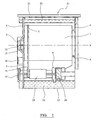
FIGURE 4 shows a sectional view of the pump assembly shown inFigure 1 ; -
FIGURE 5 is a perspective view of the pump drive shaft for the pump assembly; and -
FIGURE 6 is an exploded view of the pump assembly and rear of the tumble dryer shown inFigure 1 , including inlet and outlet pipes and pump drive shaft. - Referring to
figures 1 and2 , thetumble dryer 11 comprises arotatable drum 1 mounted within a cabinet. Thedrum 1 has an opening, into which a load, usually wet clothing items, is placed. Aheater 18 is provided for heating drying air which is contained and re-circulated within the dryer. Afan 15 forces the heated drying air from theheater 18 and into thedrum 1, where it is passed through, and drys, the wet clothing. From thedrum 1, the now moisture laden drying air is ducted into acondenser 6. Here the moisture laden drying air is cooled by air drawn in from the atmosphere by asecond fan 10. Amotor 20 drives bothfans drum 1 simultaneously. - The
motor 20 is connected to thedrum 1 via adrive belt 19. Themotor 20 drives the rotation of thedrum 1, which tumbles the clothes within thedrum 1, and increases the drying rate of the clothing and ensures even distribution of the clothes within thedrum 1. Thedrum 1 may be supported for rotation at the front and rear of thedrum 1 byfront support members 4 andrear support members 5. Thefront 4 and rear 5 support members are rotational bearings, such as roller bearings or ball bearings, or any other suitable support means which enable rotation. Therear support members 5 may directly support thedrum 1. Alternatively, or additionally a drum shaft may be provided which extends from the rear of thedrum 1 and may be coaxial with thedrum 1 and drumrotational axis 9. The drum shaft is rotationally supported by a support member such as a bearing thereby supporting the rear of thedrum 1. In this embodiment apump drive shaft 13, which will be described further may additionally comprise such a drum shaft. - The heated drying air within the
drum 1 penetrates the wet clothing therein, and acts to heat the clothing and evaporate the moisture from the clothing. The then moisture laden drying air is removed from within thedrum 1, and passed to acondenser 6. Thecondenser 6 condenses the moisture from the moisture laden drying air. As the moisture has been removed from the drying air, the drying air is recirculated within thedryer 11 and passed back into thedrum 1 via theheater 18 to further dry the clothing. - The condensate which is condensed out of the moisture laden drying air by the
condenser 6 is passed to asump tank 12, situated in the base of thetumble dryer 11. As the clothes within thedrum 1 are dried, thesump tank 12 slowly fills with thecondensate 23. Eventually, it becomes necessary to empty thecondensate 23 which is collected in thesump tank 12. - The space within the base of a
tumble dryer 11 is severely restricted, due to the requirement to locate a motor, support members, and a sump tank, etc. as well as maximise the size of thedrum 1. Hence, designing a sump tank which is easily removable from the base of atumble dryer 11 for emptying of the condensate is problematic. Furthermore, for a user to be required to bend down to remove a condensate filled drawer from the base of adryer 11 is both inconvenient and a potential safety hazard. - The
condensate 23 is therefore transferred from thesump 12 to astorage reservoir 21 at the top of thetumble dryer 11, where space is more readily available and were it may more easily be emptied. When thestorage reservoir 21 becomes full withcondensate 23, it may be slidably removed from thetumble dryer 11, emptied, and returned to thetumble dryer 11. Preferably, thestorage reservoir 21 is positioned at a convenient height relative to a user, to enable the user to easily, and without risk of injury, remove the storage reservoir for emptying. Alternatively, thecondensate 23 may be pumped directly to a drainage system. - The
condensate 23 is transported from thesump 12 to thestorage reservoir 21, or to a drainage system, by a pumping system. The pumping system comprises apump 3, apump inlet pipe 7 and apump outlet pipe 8.Pump inlet pipe 7 transportscondensate 23 from thesump 12 to thepump 3, and pumpoutlet pipe 8 transportscondensate 23 from thepump 3 to thestorage reservoir 21. - Referring to
figure 3 , thepump 3 is preferably a peristaltic pump, although it will be appreciated that other suitable pumps may be used. Thepump 3 comprises a pump casing, consisting of a frontpump casing section 29 and a backpump casing section 27, apump drive shaft 13,flexible tubing member 32, and arotor 31 having first 30 and second 26 rollers attached to the external circumference thereof. Therotor 31 may however include more or fewer than two rollers in other embodiments. The pump also comprises aninlet 14, and anoutlet 16. - In operation the pump is arranged such that at any time, at least one of the first 30 and second 26 rollers of the
pump 3 engage and compress theflexible tubing 32 such that the internal bore 35 of the tubing 35 is locally closed where the rollers contact the tubing forming aseal 24 at these points (i.e the roller forms a pinch point in the tubing 32). As therotor 30 rotates, sealed point moves along thetubing 32 and force thecondensate 23 contained within the tubing above the sealed section through and along thetubing 32, resulting in a pumping action which drawscondensate 23 from thesump 12 viapump inlet pipe 5, into thepump 3 via theinlet 14, and forcescondensate 23 out of thepump 3 via theoutlet 16 to thestorage reservoir 21 viapump outlet pipe 8. For effective pumping of liquid with such a peristaltic pump, once a first pinch point has been formed by a first roller, it should not be released until a second pinch point has been formed by a second roller, thereby preventing back-flow of liquid within the tubing when the first roller disengages the tubing. Therefore, the first 30 and second 26 rollers are diametrically opposed on therotor 30, and the tubing oriented through at least 180°, such that the second roller engages the tubing forming a pinch point, before the tubing is disengaged by the first roller. In alternative embodiments additional rollers may be provided, which allows the tubing to be oriented through a lesser angle. Alternatively, a single roller may be provided with the tubing looping around more than 360° in a complete loop and helix with the roller simultaneously acting on two sections of the looped tubing. - The
pump 3 may operate in both forward and reverse directions. Theterms inlet 14 andoutlet 16 are functional and relate to the forward operation of thepump 3. It will be appreciated that during reverse operation of thepump 3, theinlet 14 will functionally operate as the outlet, and likewise liquid will enter thepump 3 via theoutlet 16. - The
rotor 31 is supported for rotation on a projectingspigot 34 in the backpump casing section 27. Therotor 31 is driven by thepump drive shaft 13, which projects into and within thepump casing spigot 34. Arectangular end section 28 of thepump drive shaft 13 is received by a correspondingly shaped aperture in therotor 31 to enable rotational engagement of thepump drive shaft 13 with therotor 31. Alternative methods of connection may however be used, such as a cross spline, keyed shaft or any other suitable connection means. - The
pump drive shaft 13 is driven directly by the rotation of thedrum 1. To facilitate the direct drive of thepump drive shaft 13 by thedrum 1, thepump 3 is positioned such that thepump drive shaft 13 and thedrum 1 share a commonrotational axis 9, co-axial with the rotational axis of thedrum 1. Preferably, thepump drive shaft 13 is connected directly to thedrum 1. Thepump drive shaft 13 is provided with anend plate 17 havingmultiple apertures 25 radially positioned around its periphery. Theend plate 17 is secured by bolts via theapertures 25, or by other suitable securing means, to thedrum 1. In this way, thepump drive shaft 13 is linked directly to thedrum 1, such that rotation of thedrum 1 drives the rotation of thepump drive shaft 13 and hence thepump 3. Alternatively, thepump drive shaft 13 may be connected to a drum shaft intermediate thepump drive shaft 13 and thedrum 1. - The
pump 3 is preferably located on the exterior of the tumble dryer cabinet, and is preferably affixed to a rear tumble dryer cabinet panel via the backpump casing section 27, as shown infigure 4 . - To prevent overflow, the
sump tank 12 is preferably provided with a floatation switch 35 which initiates remedial action, such as deactivation of the tumble dryer heating element, when the condensate exceeds a certain level. Thestorage reservoir 21 may also be provided with a flotation switch 35. The provision of a sump flotation switch 35 also provides a safety measure to prevent damage to the clothing with thedrum 1. In the event that thedrum 1 stops rotating, for example if thebelt 19 fails, theheater 18 will remain active, and as the clothing is not being rotated, the clothing adjacent the heated drying air inlet will receive prolonged heating which may cause damage. However, as thepump 3 is driven by rotation of thedrum 1, if thedrum 1 stops moving thepump 3 will also stop. Therefore, as thecondensate 23 is not being pumped away from thesump 12, the liquid level will rise. When the liquid reaches a predetermined level, the flotation switch 35 is activated causing theheater 18 to be deactivated. - Similarly, rotation of the
drum 1 in the reverse direction for a prolonged period should be avoided, as tumble dryer fans operate most efficiently in the forward direction, and therefore air flow is reduced in the reverse direction which can lead to over heating. If thedrum 1 rotates in the reverse direction pumping is discontinued or reversed. Hence, if thedrum 1 continues to rotate in the reverse direction for a prolonged period, for example due to a control failure, the flotation switch 35 will deactivate theheater 18, thereby preventing damage due to overheating. - Providing a
pump 3 which is directly driven by the rotation of thedrum 1 of a tumble dryer obviates the need for a secondary means for driving thepump 3, such as an electric motor or a belt drive linked to the drum, as is required by current pumping systems. This advantageously reduces costs and also the noise level associated with the alternative drive means. In addition, driving apump 3 directly from thedrum 1 ensures thepump 3 rotates at the same speed as thedrum 1; in normal use, this will usually be a speed of 50rpm. In belt driven systems, which utilise idler pulleys to drive thepump 3, the rotational speeds are of the order of 300-500 rpm. Such high rotational speeds do not produce a flow rate suitable for the operational range of a peristaltic pump, or for the application concerned. Furthermore, rotational speeds of this magnitude reduce reliability due to excessive wear on the component parts of a pump. By driving thepump 3 directly from thedrum 1, and thereby significantly reducing the rotational speed of thepump 3, an optimum flow rate is achieved, and the reliability of thepump 3 is greatly increased. The use of additional belts and/or idler pulleys, which add complexity, and increases the number of parts, and hence increases cost, and also the rate of mechanical failure, is also advantageously obviated by the present invention. Slippage in the drive and other problems associated with belt or other drive arrangements are also eliminated. - Direct drive from the drum also, in use, utilises the momentum from the rotating drum with the clothes therein to assist in directly driving the pump.
- The principle and mode of operation of this invention have been explained and illustrated in its preferred embodiment. However, it must be understood that this invention may be practised otherwise than as specifically explained and illustrated without departing from its scope.
Claims (14)
- A pumping system for a condenser tumble dryer (11) comprising a sump (12), and a drum (1); the pumping system comprising:a pump (3) for pumping condensate from the sump (12), the pump (3) including a pump drive shaft (13) for driving the pump (3),characterised in that the pump drive shaft (13) is directly driven from and by rotation of the drum (1).
- The pumping system of claim 1 further comprising a storage reservoir (21), wherein the pump (3) pumps condensate from the sump (12) to the storage reservoir (21).
- The pumping system of claims 1 or 2 wherein the pump drive shaft (13) is co-axial with a rotational axis (9) of the drum (1).
- The pumping system of any preceding claim, wherein the drum (1) is connected to the pump drive shaft (13).
- The pumping system of any one of claims 1 to 3, further comprising a drum shaft.
- The pumping system of claim 5, wherein the drum shaft is connected to, and coaxial with the pump drive shaft (13).
- The pumping system of claim 5, wherein the pump drive shaft (13) and the drum shaft are the same.
- The pumping system of any preceding claim, wherein the pump (3) is a peristaltic pump.
- The pumping system of claim 8, wherein the pump (3) comprises at least two rollers (26,30).
- The pumping system of any preceding claim, further comprising a tumble dryer cabinet.
- The pumping system of claim 10, wherein the pump (3) is located outside of the tumble dryer cabinet.
- The pumping system of any preceding claim, wherein the sump (12) is provided with a flotation switch such that the flotation switch is activated when the level of liquid within the sump (12) exceeds a predetermined level.
- The pumping system of claim 12, wherein activation of the flotation switch deactivates a tumble dryer heating element (18).
- A tumble dryer including a pumping system of any one of claims 1 to 13.
Applications Claiming Priority (2)
| Application Number | Priority Date | Filing Date | Title |
|---|---|---|---|
| GB0514310A GB2428287A (en) | 2005-07-13 | 2005-07-13 | Pumping system for a condenser tumble dryer |
| PCT/GB2006/002567 WO2007007089A1 (en) | 2005-07-13 | 2006-07-11 | Pumping system for a tumble dryer |
Publications (2)
| Publication Number | Publication Date |
|---|---|
| EP1907620A1 EP1907620A1 (en) | 2008-04-09 |
| EP1907620B1 true EP1907620B1 (en) | 2010-11-17 |
Family
ID=34897122
Family Applications (1)
| Application Number | Title | Priority Date | Filing Date |
|---|---|---|---|
| EP06755767A Not-in-force EP1907620B1 (en) | 2005-07-13 | 2006-07-11 | Pumping system for a tumble dryer |
Country Status (6)
| Country | Link |
|---|---|
| EP (1) | EP1907620B1 (en) |
| AT (1) | ATE488635T1 (en) |
| DE (1) | DE602006018315D1 (en) |
| GB (1) | GB2428287A (en) |
| RU (1) | RU2380464C2 (en) |
| WO (1) | WO2007007089A1 (en) |
Cited By (3)
| Publication number | Priority date | Publication date | Assignee | Title |
|---|---|---|---|---|
| EP3351678A1 (en) | 2017-01-24 | 2018-07-25 | Whirlpool Corporation | Machine for drying laundry including a heat pump unit and operational method thereof |
| US12252835B2 (en) | 2021-07-01 | 2025-03-18 | Haier Us Appliance Solutions, Inc. | Fluid infusing system driven by dryer drum |
| US12559880B2 (en) | 2022-03-17 | 2026-02-24 | Haier Us Appliance Solutions, Inc. | Dryer appliance and infuser assembly |
Families Citing this family (6)
| Publication number | Priority date | Publication date | Assignee | Title |
|---|---|---|---|---|
| DE102013102510A1 (en) * | 2013-03-13 | 2014-09-18 | Miele & Cie. Kg | Housing for household appliances, such as a tumble dryer, a washing machine or the like |
| DE102013102511A1 (en) * | 2013-03-13 | 2014-09-18 | Miele & Cie. Kg | Housing for household appliances such as a tumble dryer, a washing machine, or the like |
| KR102119538B1 (en) * | 2013-04-03 | 2020-06-08 | 삼성전자주식회사 | Clothing Dryer |
| PL3004450T3 (en) * | 2013-05-24 | 2023-02-06 | Electrolux Appliances Aktiebolag | Laundry dryer and method of operating a laundry dryer |
| CN107034651B (en) * | 2017-04-17 | 2019-06-21 | 吴江天星纺织有限公司 | Self-lubricating structure of peristaltic pump for garment ironing and setting machine |
| CN109811532B (en) * | 2017-04-17 | 2020-09-08 | 台州市涌星贸易有限公司 | Clothes finishing method |
Family Cites Families (9)
| Publication number | Priority date | Publication date | Assignee | Title |
|---|---|---|---|---|
| GB972411A (en) * | 1961-08-03 | 1964-10-14 | Borg Warner | Combination washer-dryer |
| US3148523A (en) * | 1962-02-07 | 1964-09-15 | Philco Corp | Laundry apparatus |
| DE2135397A1 (en) * | 1971-07-15 | 1973-01-25 | Licentia Gmbh | DRYING DEVICE |
| DE2219889B1 (en) * | 1972-04-22 | 1973-05-24 | Licentia Patent-Verwaltungs-Gmbh, 6000 Frankfurt | Washer dryer |
| DE3135293A1 (en) * | 1981-09-05 | 1983-03-24 | Licentia Patent-Verwaltungs-Gmbh, 6000 Frankfurt | Laundry dryer with a condensation device |
| DE3216592C2 (en) * | 1982-05-04 | 1985-11-21 | Miele & Cie GmbH & Co, 4830 Gütersloh | Pump-out device for the condensation device of a tumble dryer |
| DE3933949A1 (en) * | 1989-10-11 | 1991-04-18 | Licentia Gmbh | Condensation laundry dryer - having horizontally revolving drum with hose pump |
| FR2718494B1 (en) * | 1994-04-11 | 1997-10-24 | Bosch Siemens Hausgeraete | Condensate pump for a dryer. |
| DE4436673B4 (en) * | 1994-10-13 | 2007-02-08 | BSH Bosch und Siemens Hausgeräte GmbH | Automatic washing machine set up for drying |
-
2005
- 2005-07-13 GB GB0514310A patent/GB2428287A/en not_active Withdrawn
-
2006
- 2006-07-11 AT AT06755767T patent/ATE488635T1/en not_active IP Right Cessation
- 2006-07-11 WO PCT/GB2006/002567 patent/WO2007007089A1/en not_active Ceased
- 2006-07-11 DE DE602006018315T patent/DE602006018315D1/en active Active
- 2006-07-11 RU RU2008105395/12A patent/RU2380464C2/en not_active IP Right Cessation
- 2006-07-11 EP EP06755767A patent/EP1907620B1/en not_active Not-in-force
Cited By (3)
| Publication number | Priority date | Publication date | Assignee | Title |
|---|---|---|---|---|
| EP3351678A1 (en) | 2017-01-24 | 2018-07-25 | Whirlpool Corporation | Machine for drying laundry including a heat pump unit and operational method thereof |
| US12252835B2 (en) | 2021-07-01 | 2025-03-18 | Haier Us Appliance Solutions, Inc. | Fluid infusing system driven by dryer drum |
| US12559880B2 (en) | 2022-03-17 | 2026-02-24 | Haier Us Appliance Solutions, Inc. | Dryer appliance and infuser assembly |
Also Published As
| Publication number | Publication date |
|---|---|
| EP1907620A1 (en) | 2008-04-09 |
| RU2380464C2 (en) | 2010-01-27 |
| ATE488635T1 (en) | 2010-12-15 |
| WO2007007089A1 (en) | 2007-01-18 |
| GB2428287A (en) | 2007-01-24 |
| GB0514310D0 (en) | 2005-08-17 |
| RU2008105395A (en) | 2009-08-20 |
| DE602006018315D1 (en) | 2010-12-30 |
Similar Documents
| Publication | Publication Date | Title |
|---|---|---|
| AU2012289035B2 (en) | Basement arrangement in heat pump laundry treatment apparatus | |
| US6151795A (en) | Flat material dryer | |
| US20100107703A1 (en) | Drum-type washer/dryer | |
| CN1187492C (en) | Drum type washing drier | |
| CN100554562C (en) | Washing dryer | |
| EP3112528B1 (en) | Dryer | |
| EP3112529B1 (en) | Dryer | |
| EP1907620A1 (en) | Pumping system for a tumble dryer | |
| KR101306679B1 (en) | Apparatus for food garbage treatment | |
| EP3112527B1 (en) | Dryer | |
| WO2014181493A1 (en) | Washing and drying machine | |
| AU2021356514A1 (en) | Clothing processing apparatus | |
| CA1060779A (en) | Condenser apparatus | |
| CN113136714A (en) | laundry treatment equipment | |
| RU2291923C1 (en) | Drainage pump and drum-type washing machine equipped with such a drainage pump | |
| EP2661521B1 (en) | Household appliance, in particular laundry dryer | |
| EP2666901B1 (en) | Tumble-dryer machine | |
| EP3029194A1 (en) | Laundry dryer | |
| CN100503954C (en) | Drum washing machine with drying function | |
| CN212505509U (en) | Cylindrical gear driven drying roller structure | |
| JP4525463B2 (en) | Washing and drying machine | |
| JP2008113944A (en) | Clothes dryer | |
| KR100664288B1 (en) | Drive system of clothes dryer | |
| CN223292824U (en) | clothes dryer | |
| CN223150887U (en) | Clothes dryer |
Legal Events
| Date | Code | Title | Description |
|---|---|---|---|
| PUAI | Public reference made under article 153(3) epc to a published international application that has entered the european phase |
Free format text: ORIGINAL CODE: 0009012 |
|
| 17P | Request for examination filed |
Effective date: 20071220 |
|
| AK | Designated contracting states |
Kind code of ref document: A1 Designated state(s): AT BE BG CH CY CZ DE DK EE ES FI FR GB GR HU IE IS IT LI LT LU LV MC NL PL PT RO SE SI SK TR |
|
| GRAP | Despatch of communication of intention to grant a patent |
Free format text: ORIGINAL CODE: EPIDOSNIGR1 |
|
| DAX | Request for extension of the european patent (deleted) | ||
| GRAS | Grant fee paid |
Free format text: ORIGINAL CODE: EPIDOSNIGR3 |
|
| GRAA | (expected) grant |
Free format text: ORIGINAL CODE: 0009210 |
|
| AK | Designated contracting states |
Kind code of ref document: B1 Designated state(s): AT BE BG CH CY CZ DE DK EE ES FI FR GB GR HU IE IS IT LI LT LU LV MC NL PL PT RO SE SI SK TR |
|
| REG | Reference to a national code |
Ref country code: GB Ref legal event code: FG4D |
|
| REG | Reference to a national code |
Ref country code: CH Ref legal event code: EP |
|
| REG | Reference to a national code |
Ref country code: IE Ref legal event code: FG4D |
|
| REF | Corresponds to: |
Ref document number: 602006018315 Country of ref document: DE Date of ref document: 20101230 Kind code of ref document: P |
|
| REG | Reference to a national code |
Ref country code: NL Ref legal event code: VDEP Effective date: 20101117 |
|
| LTIE | Lt: invalidation of european patent or patent extension |
Effective date: 20101117 |
|
| PG25 | Lapsed in a contracting state [announced via postgrant information from national office to epo] |
Ref country code: LT Free format text: LAPSE BECAUSE OF FAILURE TO SUBMIT A TRANSLATION OF THE DESCRIPTION OR TO PAY THE FEE WITHIN THE PRESCRIBED TIME-LIMIT Effective date: 20101117 |
|
| PG25 | Lapsed in a contracting state [announced via postgrant information from national office to epo] |
Ref country code: CY Free format text: LAPSE BECAUSE OF FAILURE TO SUBMIT A TRANSLATION OF THE DESCRIPTION OR TO PAY THE FEE WITHIN THE PRESCRIBED TIME-LIMIT Effective date: 20101117 Ref country code: NL Free format text: LAPSE BECAUSE OF FAILURE TO SUBMIT A TRANSLATION OF THE DESCRIPTION OR TO PAY THE FEE WITHIN THE PRESCRIBED TIME-LIMIT Effective date: 20101117 Ref country code: LV Free format text: LAPSE BECAUSE OF FAILURE TO SUBMIT A TRANSLATION OF THE DESCRIPTION OR TO PAY THE FEE WITHIN THE PRESCRIBED TIME-LIMIT Effective date: 20101117 Ref country code: IS Free format text: LAPSE BECAUSE OF FAILURE TO SUBMIT A TRANSLATION OF THE DESCRIPTION OR TO PAY THE FEE WITHIN THE PRESCRIBED TIME-LIMIT Effective date: 20110317 Ref country code: FI Free format text: LAPSE BECAUSE OF FAILURE TO SUBMIT A TRANSLATION OF THE DESCRIPTION OR TO PAY THE FEE WITHIN THE PRESCRIBED TIME-LIMIT Effective date: 20101117 Ref country code: SE Free format text: LAPSE BECAUSE OF FAILURE TO SUBMIT A TRANSLATION OF THE DESCRIPTION OR TO PAY THE FEE WITHIN THE PRESCRIBED TIME-LIMIT Effective date: 20101117 Ref country code: PT Free format text: LAPSE BECAUSE OF FAILURE TO SUBMIT A TRANSLATION OF THE DESCRIPTION OR TO PAY THE FEE WITHIN THE PRESCRIBED TIME-LIMIT Effective date: 20110317 Ref country code: BG Free format text: LAPSE BECAUSE OF FAILURE TO SUBMIT A TRANSLATION OF THE DESCRIPTION OR TO PAY THE FEE WITHIN THE PRESCRIBED TIME-LIMIT Effective date: 20110217 Ref country code: SI Free format text: LAPSE BECAUSE OF FAILURE TO SUBMIT A TRANSLATION OF THE DESCRIPTION OR TO PAY THE FEE WITHIN THE PRESCRIBED TIME-LIMIT Effective date: 20101117 Ref country code: AT Free format text: LAPSE BECAUSE OF FAILURE TO SUBMIT A TRANSLATION OF THE DESCRIPTION OR TO PAY THE FEE WITHIN THE PRESCRIBED TIME-LIMIT Effective date: 20101117 |
|
| PG25 | Lapsed in a contracting state [announced via postgrant information from national office to epo] |
Ref country code: GR Free format text: LAPSE BECAUSE OF FAILURE TO SUBMIT A TRANSLATION OF THE DESCRIPTION OR TO PAY THE FEE WITHIN THE PRESCRIBED TIME-LIMIT Effective date: 20110218 |
|
| PG25 | Lapsed in a contracting state [announced via postgrant information from national office to epo] |
Ref country code: ES Free format text: LAPSE BECAUSE OF FAILURE TO SUBMIT A TRANSLATION OF THE DESCRIPTION OR TO PAY THE FEE WITHIN THE PRESCRIBED TIME-LIMIT Effective date: 20110228 Ref country code: EE Free format text: LAPSE BECAUSE OF FAILURE TO SUBMIT A TRANSLATION OF THE DESCRIPTION OR TO PAY THE FEE WITHIN THE PRESCRIBED TIME-LIMIT Effective date: 20101117 Ref country code: BE Free format text: LAPSE BECAUSE OF FAILURE TO SUBMIT A TRANSLATION OF THE DESCRIPTION OR TO PAY THE FEE WITHIN THE PRESCRIBED TIME-LIMIT Effective date: 20101117 Ref country code: CZ Free format text: LAPSE BECAUSE OF FAILURE TO SUBMIT A TRANSLATION OF THE DESCRIPTION OR TO PAY THE FEE WITHIN THE PRESCRIBED TIME-LIMIT Effective date: 20101117 |
|
| PG25 | Lapsed in a contracting state [announced via postgrant information from national office to epo] |
Ref country code: SK Free format text: LAPSE BECAUSE OF FAILURE TO SUBMIT A TRANSLATION OF THE DESCRIPTION OR TO PAY THE FEE WITHIN THE PRESCRIBED TIME-LIMIT Effective date: 20101117 Ref country code: RO Free format text: LAPSE BECAUSE OF FAILURE TO SUBMIT A TRANSLATION OF THE DESCRIPTION OR TO PAY THE FEE WITHIN THE PRESCRIBED TIME-LIMIT Effective date: 20101117 Ref country code: PL Free format text: LAPSE BECAUSE OF FAILURE TO SUBMIT A TRANSLATION OF THE DESCRIPTION OR TO PAY THE FEE WITHIN THE PRESCRIBED TIME-LIMIT Effective date: 20101117 Ref country code: DK Free format text: LAPSE BECAUSE OF FAILURE TO SUBMIT A TRANSLATION OF THE DESCRIPTION OR TO PAY THE FEE WITHIN THE PRESCRIBED TIME-LIMIT Effective date: 20101117 |
|
| PLBE | No opposition filed within time limit |
Free format text: ORIGINAL CODE: 0009261 |
|
| STAA | Information on the status of an ep patent application or granted ep patent |
Free format text: STATUS: NO OPPOSITION FILED WITHIN TIME LIMIT |
|
| 26N | No opposition filed |
Effective date: 20110818 |
|
| PGFP | Annual fee paid to national office [announced via postgrant information from national office to epo] |
Ref country code: DE Payment date: 20110729 Year of fee payment: 6 |
|
| REG | Reference to a national code |
Ref country code: DE Ref legal event code: R097 Ref document number: 602006018315 Country of ref document: DE Effective date: 20110818 |
|
| PGFP | Annual fee paid to national office [announced via postgrant information from national office to epo] |
Ref country code: IT Payment date: 20110729 Year of fee payment: 6 |
|
| PG25 | Lapsed in a contracting state [announced via postgrant information from national office to epo] |
Ref country code: MC Free format text: LAPSE BECAUSE OF NON-PAYMENT OF DUE FEES Effective date: 20110731 |
|
| REG | Reference to a national code |
Ref country code: CH Ref legal event code: PL |
|
| REG | Reference to a national code |
Ref country code: FR Ref legal event code: ST Effective date: 20120330 |
|
| REG | Reference to a national code |
Ref country code: IE Ref legal event code: MM4A |
|
| PG25 | Lapsed in a contracting state [announced via postgrant information from national office to epo] |
Ref country code: FR Free format text: LAPSE BECAUSE OF NON-PAYMENT OF DUE FEES Effective date: 20110801 Ref country code: LI Free format text: LAPSE BECAUSE OF NON-PAYMENT OF DUE FEES Effective date: 20110731 Ref country code: CH Free format text: LAPSE BECAUSE OF NON-PAYMENT OF DUE FEES Effective date: 20110731 |
|
| PG25 | Lapsed in a contracting state [announced via postgrant information from national office to epo] |
Ref country code: IE Free format text: LAPSE BECAUSE OF NON-PAYMENT OF DUE FEES Effective date: 20110711 |
|
| PG25 | Lapsed in a contracting state [announced via postgrant information from national office to epo] |
Ref country code: DE Free format text: LAPSE BECAUSE OF NON-PAYMENT OF DUE FEES Effective date: 20130201 |
|
| REG | Reference to a national code |
Ref country code: DE Ref legal event code: R119 Ref document number: 602006018315 Country of ref document: DE Effective date: 20130201 |
|
| PG25 | Lapsed in a contracting state [announced via postgrant information from national office to epo] |
Ref country code: LU Free format text: LAPSE BECAUSE OF NON-PAYMENT OF DUE FEES Effective date: 20110711 Ref country code: IT Free format text: LAPSE BECAUSE OF NON-PAYMENT OF DUE FEES Effective date: 20120711 |
|
| PG25 | Lapsed in a contracting state [announced via postgrant information from national office to epo] |
Ref country code: TR Free format text: LAPSE BECAUSE OF FAILURE TO SUBMIT A TRANSLATION OF THE DESCRIPTION OR TO PAY THE FEE WITHIN THE PRESCRIBED TIME-LIMIT Effective date: 20101117 |
|
| PG25 | Lapsed in a contracting state [announced via postgrant information from national office to epo] |
Ref country code: HU Free format text: LAPSE BECAUSE OF FAILURE TO SUBMIT A TRANSLATION OF THE DESCRIPTION OR TO PAY THE FEE WITHIN THE PRESCRIBED TIME-LIMIT Effective date: 20101117 |
|
| PGFP | Annual fee paid to national office [announced via postgrant information from national office to epo] |
Ref country code: GB Payment date: 20180711 Year of fee payment: 13 |
|
| GBPC | Gb: european patent ceased through non-payment of renewal fee |
Effective date: 20190711 |
|
| PG25 | Lapsed in a contracting state [announced via postgrant information from national office to epo] |
Ref country code: GB Free format text: LAPSE BECAUSE OF NON-PAYMENT OF DUE FEES Effective date: 20190711 |