EP1907310B1 - Anhänger für ein kraftfahrzeug - Google Patents
Anhänger für ein kraftfahrzeug Download PDFInfo
- Publication number
- EP1907310B1 EP1907310B1 EP05740666A EP05740666A EP1907310B1 EP 1907310 B1 EP1907310 B1 EP 1907310B1 EP 05740666 A EP05740666 A EP 05740666A EP 05740666 A EP05740666 A EP 05740666A EP 1907310 B1 EP1907310 B1 EP 1907310B1
- Authority
- EP
- European Patent Office
- Prior art keywords
- trailer
- forklift device
- hubstaplervorrichtung
- frame
- wheels
- Prior art date
- Legal status (The legal status is an assumption and is not a legal conclusion. Google has not performed a legal analysis and makes no representation as to the accuracy of the status listed.)
- Active
Links
Images


Classifications
-
- B—PERFORMING OPERATIONS; TRANSPORTING
- B66—HOISTING; LIFTING; HAULING
- B66F—HOISTING, LIFTING, HAULING OR PUSHING, NOT OTHERWISE PROVIDED FOR, e.g. DEVICES WHICH APPLY A LIFTING OR PUSHING FORCE DIRECTLY TO THE SURFACE OF A LOAD
- B66F9/00—Devices for lifting or lowering bulky or heavy goods for loading or unloading purposes
- B66F9/06—Devices for lifting or lowering bulky or heavy goods for loading or unloading purposes movable, with their loads, on wheels or the like, e.g. fork-lift trucks
- B66F9/075—Constructional features or details
- B66F9/08—Masts; Guides; Chains
- B66F9/10—Masts; Guides; Chains movable in a horizontal direction relative to truck
-
- B—PERFORMING OPERATIONS; TRANSPORTING
- B60—VEHICLES IN GENERAL
- B60P—VEHICLES ADAPTED FOR LOAD TRANSPORTATION OR TO TRANSPORT, TO CARRY, OR TO COMPRISE SPECIAL LOADS OR OBJECTS
- B60P1/00—Vehicles predominantly for transporting loads and modified to facilitate loading, consolidating the load, or unloading
- B60P1/02—Vehicles predominantly for transporting loads and modified to facilitate loading, consolidating the load, or unloading with parallel up-and-down movement of load supporting or containing element
- B60P1/025—Vehicles predominantly for transporting loads and modified to facilitate loading, consolidating the load, or unloading with parallel up-and-down movement of load supporting or containing element with a loading platform inside the wheels of a same axle and being lowerable below the axle
-
- B—PERFORMING OPERATIONS; TRANSPORTING
- B62—LAND VEHICLES FOR TRAVELLING OTHERWISE THAN ON RAILS
- B62D—MOTOR VEHICLES; TRAILERS
- B62D63/00—Motor vehicles or trailers not otherwise provided for
- B62D63/06—Trailers
-
- B—PERFORMING OPERATIONS; TRANSPORTING
- B66—HOISTING; LIFTING; HAULING
- B66F—HOISTING, LIFTING, HAULING OR PUSHING, NOT OTHERWISE PROVIDED FOR, e.g. DEVICES WHICH APPLY A LIFTING OR PUSHING FORCE DIRECTLY TO THE SURFACE OF A LOAD
- B66F9/00—Devices for lifting or lowering bulky or heavy goods for loading or unloading purposes
- B66F9/06—Devices for lifting or lowering bulky or heavy goods for loading or unloading purposes movable, with their loads, on wheels or the like, e.g. fork-lift trucks
Definitions
- the invention relates to a two-axle trailer for a motor vehicle with a trailer frame, on the frame longitudinal elements two longitudinally spaced pairs of wheels are arranged, and a mounted inside the trailer Hubstaplervor substances which Hubstaplervortechnisch within the trailer between a transposition, in the load can be transported, and a loading position in the load with the Hubstaplervorlase is raised and lowered, is displaceable, wherein at least one cross-connecting element is provided which connects the frame longitudinal elements in the wheels, and that the loading position of the Hubstaplervortechnisch - in the direction of travel Seen - is located immediately behind the at least one cross-connecting element, so that the Hubstaplervortechnisch is lowered to the ground level on which the trailer is.
- GB 2 145 995 A For example, there is shown a uniaxial U-shaped frame trailer and a lift truck apparatus having longitudinally extending fork arms for receiving cargo.
- the GB 2 153 339 A describes a uniaxial forklift trailer for agricultural tractors whose frame is composed essentially of two longitudinal elements and two cross-connection elements for the displaceable between a transport position and a loading position forklift device a corresponding counterweight is provided on the trailer drawbar, which compensates for the overturning moments occurring during loading , while driving is to be carried as an additional load from the trailer hitch.
- the forklift device can be lowered to the floor behind the cross connection elements in order to be able to pick up the load to be transported.
- a trailer is shown with a horizontally movable Hubstaplervorraum for carrying out loading work, which has a U-shaped trailer frame.
- Hubstaplervoriques By integrated in the trailer Hubstaplervoriques the transport of eg only a pallet of building material can be done very efficiently by this pallet can be delivered to the trailer and then unloaded with the Hubstaplervorides, without the need for a separate crane or forklift on site. Regardless of whether at the place of delivery mechanical charging devices are present or not, so can the Transporting the load and unloading or loading can be done very quickly. For example, if additional material is required on a construction site, this can be picked up immediately from a hardware store, without having to take account of order times and freight costs.
- the Hubstaplervoriques can be brought into a loading position in which the Hubstaplervortechnische can be lowered to the ground level.
- the wheels are not mounted on a continuous axis but on stub axles on the sides of the trailer. In this way, this type of trailer can be built only with an excess width, which limits the usability.
- a relatively heavy construction if sufficient rigidity should be ensured, but this has a negative impact on the fuel consumption of the towing vehicle and on its driving characteristics.
- a trailer for receiving pallets in which a lifting bar is movably mounted by means of a chain conveyor, so that a pallet is brought by means of introduced support rods from a front trailer area behind the trailer axles and then lowered to ground level.
- the loading area is composed of a fixed and a movable loading floor, wherein the fixed loading floor is held in a square profile of the trailer frame, which includes a cross-connection between two longitudinal profiles in the region of the wheel axles.
- the object of the invention is therefore to provide a trailer of the type mentioned, with the loads of small extent can be transported so that a loading and unloading of the trailer with little effort and time is possible, the trailer but sufficient stability with low weight having.
- Another object of the invention is to provide a trailer that can be realized by simple technical means.
- the ale hollow profiles formed cross-connection elements provide increased trailer stability and also serve the wheel bearing and shock absorption. In this way, a very small width can be achieved.
- the available standing space in the trailer according to the invention are advantageously used in that the Hubstaplervoropathy is in transport position substantially in the front region of the trailer and in Verladerium substantially in the region of the or the cross-connecting element (s) or the wheel axle (s) of the trailer, wherein the Hubstaplervortechnisch in Verlade ein behind the rear cross-member and the rear axle to the ground level on which the trailer is lowered.
- the bottom wall of the trailer be at least partially removable, so that the Hubstaplervorides in the region of the at least one cross-connecting element is movable up and down.
- the bottom wall may be composed of a fixed bottom wall portion extending from the front trailer portion to the cross member (s) and a removable bottom wall portion extending from the cross tie member (s) to the rear trailer wall.
- the removable in this way bottom wall part can be removed during loading operations from the trailer according to the invention and then the Hubstaplervorraum be brought to the transition between the fixed bottom wall element and the now open bottom wall portion to perform the upward and downward movement of the Hubstaplerelements can.
- a development of the invention may consist in that the Hubstaplervoriques has a vertically movable forklift fork, preferably with two parallel fork arms.
- Standardized load elements such as pallets or the like, as well as bulk material devices or concrete mixers, which have suitable fork slots, can be loaded onto or unloaded from the trailer according to the invention in a simple manner by means of the forklift fork.
- the distance between the fork arms may be adjustable so that an adaptation to different charging devices can be made.
- an alignment of the fork arms in the longitudinal direction of the trailer should be strived for.
- a loading and unloading of the trailer from the back of the trailer is preferred, with the free ends of the fork arms are preferably oriented opposite to the direction of travel of the trailer. It can be arranged differently according to the respective requirements, the fork arms.
- the mobility of the Hubstaplervoriques of the trailer according to the invention can be done in various ways, according to an embodiment of the invention, the Hubstaplervor Vietnamese ajar, ajar, a jar, a jar, a jar, a jar, a jar, a styrene-maleic anhydride (PAS), a styrene-maleic anhydride (PAS), a staplervortechnische, a low-friction movement is possible and on the other hand, this provides a stable support to absorb the forces and tilting moments effective during a loading process can.
- a horizontally movable, hydraulically driven horizontal carriage which is reciprocated between the transport position and the loading position.
- this may have laterally mounted guide rollers which are guided in horizontally extending profile guides, which are arranged parallel to the side walls of the trailer.
- the profile guides may for example be formed by U-profiles, which are connected in parallel to the frame longitudinal elements with these and allow a secure hold of the guide rollers of the horizontally movable carriage.
- a frame with vertical guide rails can be arranged on the horizontally movable carriage, in which the Hubstaplervorides, eg vertically movable on a vertical slide.
- the cross slide can be displaced, for example via a roller bearing.
- an embodiment of the invention may consist in that the horizontally movable horizontal slide on a along the trailer longitudinal axis extending, with the carriage in operative connection threaded spindle is movable over the a spindle hand crank is drivable.
- a secure and mechanically stable determination of the trailer side boundary can be achieved that are mounted on the frame longitudinal elements side walls.
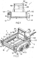
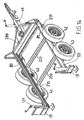
- a trailer 1 which can be pulled over a equipped with a trailer hitch 49 from a vehicle, in particular a motor vehicle of any kind, provided on the sides of the trailer 1 pairs of wheels 40, 41 and 42, 43 for locomotion are partially covered by Kotbleche 50, 51.
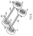
- the pairs of wheels 40, 41 and 42, 43 are attached to a trailer frame 210, 211, 289 (FIG. Figure 14 ) arranged.
- FIG 15 the front part 289 of the trailer frame is shown, which connects the two frame longitudinal members 210, 211 with the profile guides 80, 81 mounted thereon in the front region of the trailer 1 according to the invention and provides the connection point with the drawbar 49.
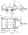
- a Hubstaplervoropathy 3 is provided, which between a transport position ( Fig.1, 2 ), in which load is transportable, and a loading position ( 3, 4 ), in the load with the Hubstaplervoruze 3 can be raised and lowered, is displaced.
- two cross-connection elements 200, 201 (FIG. Figure 13 . 14 ), which connect the parallel frame longitudinal elements 210, 211 in the region of the wheels 40, 41, 42, 43, wherein the loading position of the Hubstaplervorplatz 3 - seen in the direction of travel - is located directly behind the rear of the two cross-connection elements 200, 201, so that the Hubstaplervortechnisch 3 is lowerable to the ground level 35 on which the trailer 1 is ( Figure 7 ).
- the two cross-connection elements 200, 201 are firmly screwed to the frame longitudinal elements 210, 211 to the stability of the frame to ensure.
- Number and type of wheels and the cross-connection elements may vary within the scope of the invention, in particular, in addition to the variant shown in the figures with two cross-connection elements 200, 201 and a trailer with only one cross-connection element or with more than two cross-connection elements realized. Accordingly, the trailer according to the invention may preferably be formed two-, four- or six-wheeled, with respect to the number of wheels, there is no restriction.
- a continuous wheel axle is to be understood, which is firmly connected to the trailer frame.
- the trailer 1 can also be pulled by hand and moved.
- Assisted is an extendable castor 60, which is supported on the drawbar 49.
- Equipment details such as suspension, size, shape and equipment of the trailer 1 are not specific to the invention and can be adapted to the requirements as desired.
- the Hubstaplervoretti 3 in transport position is essentially - seen in the direction of travel - in the front region of the trailer 1, as in Fig. 1, 2 shown.
- One of the Hubstaplervorides 3 deposited on the trailer 1, in the Fig.1, 2 not shown load is located above the continuous cross-connection elements 200, 201 and thus does not cause a tilting moment during the carriage.
- the transverse connecting elements 200, 201 passing through in the region of the wheels 40, 41, 42, 43 are, as already mentioned, firmly connected to the longitudinal frame elements 210, 211 ( Figure 13 ). Furthermore, the two cross-connection elements 200, 201 are formed in a manner known per se as hollow profiles ( Figure 11 ), in the ends of bearing legs 240, 241 for supporting the wheels 40, 41, 42, 43 are guided elastically rotatable. An impact force acting on the wheels 40, 41, 42, 43 is converted into a torsion of the elastic elements present in the hollow cross-connection elements 200, 201 and thus damps the impact effect.
- the trailer width does not exceed the usual extent in this construction.
- the cross-connection elements 200, 201 extend at a right angle to the longitudinal frame parts 210, 211, but they can be arranged obliquely.
- the inner structure or the profile of the cross-connection elements 200, 201 can be adapted to the respective needs and is not limited to any particular shape.
- FIG 13 there is shown a chassis usable for the purpose of the invention, which is known in this form and can be obtained from a manufacturer. Other embodiments of chassis are also applicable.
- Essential is the between opposite wheels 40, 41 and 42, 43 extending cross-connection of the frame longitudinal members 210, 211 through the parallel cross-connection elements 200, 201 to achieve a high frame stiffness and a small width of the trailer according to the invention.
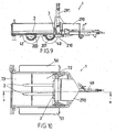
- the bottom wall 72, 73 of the trailer 1 is at least partially removable in order to settle or receive the load moved by the Hubstäplervoriques 3 as close as possible to the rear cross-connection element 200 and thus to keep the tipping load as low as possible.
- the bottom wall of the trailer 1 is composed of a fixed, from Trailer frame held bottom wall portion 72 which extends from the front trailer area to the rear cross-connection element 200 and a removable bottom wall portion 73 (FIG. Figure 10 ), which extends from the rear cross-link 200 to the rear trailer wall 15.
- the removable bottom wall portion 73 may consist of one or more boards, which rest on the frame 210, 211 or on the cross-connection elements 200, 201 and can be removed if necessary or inserted into the trailer 1.
- the removable bottom wall part 73 is already removed from the trailer 1 and a rear trailer wall 15 (FIG. Fig.2 ), which may also be designed to be pivotable or tiltable, has been taken away in order to provide space for the lift-stacker device 3.
- the extent of the fixed and the removable bottom wall portion 72, 73 can be adapted to the requirements.
- the Hubstaplervorraum 3 is understood in the context of the invention, any type of lifting device with which a load can be raised or lowered.
- the Hubstaplervorraum 3 has a vertically movable stacker fork 2, which is formed of two parallel fork arms 20, 21, which can be introduced into corresponding fork slots of a load, not shown, to raise or lower this load.
- the distance between the fork arms 20, 21 adjustable, but can also be selected rigid.
- the fork arms 20, 21 of the forklift 2 are oriented opposite to the direction of travel of the trailer 1, so that the free ends of the fork arms 20, 21 point in the direction of the back of the trailer 1.
- An actuation of the Hubstaplervortechnik 3 is done by means of a hydraulic piston 291, but it can also be driven by a spindle or in another known to those skilled in the art.
- Fig.1 the hydraulic piston 291 is shown in its extended position, which corresponds to the raised position of the Hubstaplervor substances 3.
- the Hubstaplervoretti can also be designed so that it can be raised beyond the level shown.
- the mobility between the transport position and the loading position is achieved in that the Hubstaplervoropathy 3 is arranged on a horizontally movable horizontal slide 100, which laterally mounted guide rollers 101, 102 which in horizontally extending profile guides 80, 81, preferably U-profiles, the - as in Figure 14 shown - in parallel position to the longitudinal frame members 210, 211 connected to these, in particular screwed.
- a hydraulic piston 250 which can be extended in the direction of the trailer longitudinal axis and is operatively connected to the horizontal slide 100 via a hydraulic unit accommodated in a trailer box 290, can move the horizontal slide 100 horizontally between the transport position and the loading position.
- a hydraulic unit accommodated in a trailer box 290 which is located in the front trailer area, an additional control and operating unit and a battery supply are housed weatherproof.
- the hydraulic piston 250 In the loading position of the trailer 1, the hydraulic piston 250 is fully extended ( Figure 12 ).
- a support frame 160 is mounted, which is composed of two parallel vertical guide rails 162, 163 and an upper cross member 161.
- the Hubstaplervor substances 3 is vertically movable by means of a connected thereto, via rollers, guided vertical slide 177.
- the vertical slide 177 can be moved up and down via the hydraulically actuated piston 291.
- the type of lift truck drive is given here only by way of example and can be designed differently, for example via a threaded spindle driven by a crank or by means of a cable-driven hand crank.
- the support frame 160 is on the sides with Truncated pyramidal support elements 158, 159 secured against tilting movements caused by loads.
- taillights or reflectors 18, 19 are further provided for reasons of road safety.
Priority Applications (2)
| Application Number | Priority Date | Filing Date | Title |
|---|---|---|---|
| PL05740666T PL1907310T3 (pl) | 2005-05-20 | 2005-05-20 | Przyczepa do pojazdu mechanicznego |
| SI200530559T SI1907310T1 (sl) | 2005-05-20 | 2005-05-20 | Prikolica za motorno vozilo |
Applications Claiming Priority (1)
| Application Number | Priority Date | Filing Date | Title |
|---|---|---|---|
| PCT/AT2005/000173 WO2006122336A1 (de) | 2005-05-20 | 2005-05-20 | Anhänger für ein kraftfahrzeug |
Publications (2)
| Publication Number | Publication Date |
|---|---|
| EP1907310A1 EP1907310A1 (de) | 2008-04-09 |
| EP1907310B1 true EP1907310B1 (de) | 2008-10-29 |
Family
ID=35107001
Family Applications (1)
| Application Number | Title | Priority Date | Filing Date |
|---|---|---|---|
| EP05740666A Active EP1907310B1 (de) | 2005-05-20 | 2005-05-20 | Anhänger für ein kraftfahrzeug |
Country Status (7)
| Country | Link |
|---|---|
| EP (1) | EP1907310B1 (zh) |
| CN (1) | CN101208253B (zh) |
| AT (1) | ATE412607T1 (zh) |
| BR (1) | BRPI0520261A2 (zh) |
| DE (1) | DE502005005841D1 (zh) |
| PL (1) | PL1907310T3 (zh) |
| WO (1) | WO2006122336A1 (zh) |
Families Citing this family (9)
| Publication number | Priority date | Publication date | Assignee | Title |
|---|---|---|---|---|
| DE102009023393A1 (de) * | 2009-05-29 | 2010-12-02 | Airbus Deutschland Gmbh | Transportvorrichtung zur Verwendung bei der Montage von Interieurkomponentenmodulen in einem Flugzeug |
| RU2624766C1 (ru) * | 2016-02-29 | 2017-07-06 | Федеральное государственное бюджетное образовательное учреждение высшего профессионального образования "Пензенский государственный университет" (ФГБОУ ВПО "Пензенский государственный университет") | Прицеп для транспортного средства |
| CH712469B1 (de) | 2016-05-17 | 2019-06-14 | Hanniske Kurt | Verladevorrichtung zum Ein- bzw. Ausladen einer Last in ein bzw. aus einem Transportfahrzeug und zum Transportieren einer Last. |
| AT518649B1 (de) * | 2016-07-29 | 2017-12-15 | Bulmor Holding Gmbh | Selbstfahrendes Flurfördergerät |
| WO2018030922A1 (ar) * | 2016-08-09 | 2018-02-15 | فهد الراجحي | مقطورة السحب لرفع الحُمولة ونقلها |
| NO343459B1 (en) * | 2017-06-30 | 2019-03-18 | Multicargo As | Multipurpose trailer |
| CN108639033B (zh) * | 2018-05-28 | 2024-04-09 | 徐工集团工程机械股份有限公司科技分公司 | 一种带挂车的装载机手制动系统及方法 |
| AT523849B1 (de) | 2021-03-26 | 2021-12-15 | Varch Wolfgang | Anhänger für ein Kraftfahrzeug |
| AT17376U1 (de) * | 2021-03-30 | 2022-02-15 | Varch Wolfgang | Anhänger für ein Kraftfahrzeug |
Family Cites Families (5)
| Publication number | Priority date | Publication date | Assignee | Title |
|---|---|---|---|---|
| IE831782L (en) * | 1984-01-28 | 1985-07-28 | Thomas Davies | Trailor with fork-lift loading facility |
| DE8805335U1 (zh) * | 1988-04-22 | 1988-06-23 | Willing, Hubert | |
| FR2654047A1 (fr) * | 1989-11-08 | 1991-05-10 | Morel Michel | Remorque routiere munie d'un dispositif permettant de prendre, lever, transporter, deposer une charge sur un support. |
| CN2117307U (zh) * | 1992-03-12 | 1992-09-30 | 李青春 | 叉车牵引挂车 |
| WO1995032917A1 (en) * | 1994-05-31 | 1995-12-07 | Pallet Boss Pty. Ltd. | Load transport vehicles |
-
2005
- 2005-05-20 EP EP05740666A patent/EP1907310B1/de active Active
- 2005-05-20 PL PL05740666T patent/PL1907310T3/pl unknown
- 2005-05-20 BR BRPI0520261-2A patent/BRPI0520261A2/pt not_active IP Right Cessation
- 2005-05-20 DE DE502005005841T patent/DE502005005841D1/de active Active
- 2005-05-20 WO PCT/AT2005/000173 patent/WO2006122336A1/de active Application Filing
- 2005-05-20 CN CN2005800502420A patent/CN101208253B/zh not_active Expired - Fee Related
- 2005-05-20 AT AT05740666T patent/ATE412607T1/de active
Also Published As
| Publication number | Publication date |
|---|---|
| CN101208253B (zh) | 2010-05-12 |
| BRPI0520261A2 (pt) | 2009-04-28 |
| WO2006122336A1 (de) | 2006-11-23 |
| PL1907310T3 (pl) | 2009-04-30 |
| EP1907310A1 (de) | 2008-04-09 |
| CN101208253A (zh) | 2008-06-25 |
| DE502005005841D1 (de) | 2008-12-11 |
| ATE412607T1 (de) | 2008-11-15 |
Similar Documents
| Publication | Publication Date | Title |
|---|---|---|
| EP1907310B1 (de) | Anhänger für ein kraftfahrzeug | |
| EP2443005B1 (de) | Transportsystem | |
| EP2260818B1 (de) | Ladelift | |
| EP2079607A1 (de) | Flurgebundenes transportfahrzeug, insbesondere für den transport von containern | |
| DE4335456C2 (de) | Lastkraftwagen für den Transport von Gütern | |
| EP0733003B1 (de) | Fahrzeug mit einem aufbau | |
| DE19512246C2 (de) | Selbstfahrendes und auf ein Transportfahrzeug selbstauf- und selbstabladbares Verladesystem für Container oder Wechselbrücken | |
| DE3213421C2 (zh) | ||
| WO1986002326A1 (en) | Single-axle trailer | |
| EP0850157B1 (de) | Verfahren und einrichtung zum transport von leichten gütern | |
| DE2648251A1 (de) | Lastkraftfahrzeug mit einer hebeeinrichtung | |
| AT523849B1 (de) | Anhänger für ein Kraftfahrzeug | |
| DE1277038B (de) | Fahrzeug fuer die Befoerderung grosser Einzellasten | |
| DE10019832A1 (de) | Einrichtung zur Montage von Wechselaufbauten an Lastkraftwagen bzw. an deren Anhänger | |
| DE10043398A1 (de) | Verfahren zum Beladen von Fahrzeugen | |
| EP0901427B1 (de) | Laderaum eines kraftfahrzeuges | |
| EP0883513B1 (de) | Schnellwechseleinrichtung, einrichtung sowie verwendung derselben zum transport von leichten gütern | |
| DE202007010664U1 (de) | Vorrichtung zum Wenden von Rollwagen | |
| EP3604072B1 (de) | Hebbare tragvorrichtung | |
| WO2006012652A1 (de) | Anhänger für ein kraftfahrzeug | |
| WO2006047796A1 (de) | Anhänger für ein kraftfahrzeug | |
| WO2016042147A1 (de) | Lastkraftwagen mit einer hubeinrichtung für container | |
| EP1541501A1 (de) | Transporteinheit | |
| WO2006039728A1 (de) | Transportbehälter für ladegut | |
| DE10250852A1 (de) | Verfahren und Vorrichtungen zur Aufnahme von Wechselmulden |
Legal Events
| Date | Code | Title | Description |
|---|---|---|---|
| PUAI | Public reference made under article 153(3) epc to a published international application that has entered the european phase |
Free format text: ORIGINAL CODE: 0009012 |
|
| 17P | Request for examination filed |
Effective date: 20071214 |
|
| AK | Designated contracting states |
Kind code of ref document: A1 Designated state(s): AT BE BG CH CY CZ DE DK EE ES FI FR GB GR HU IE IS IT LI LT LU MC NL PL PT RO SE SI SK TR |
|
| AX | Request for extension of the european patent |
Extension state: AL BA HR LV MK YU |
|
| GRAP | Despatch of communication of intention to grant a patent |
Free format text: ORIGINAL CODE: EPIDOSNIGR1 |
|
| GRAS | Grant fee paid |
Free format text: ORIGINAL CODE: EPIDOSNIGR3 |
|
| GRAA | (expected) grant |
Free format text: ORIGINAL CODE: 0009210 |
|
| AK | Designated contracting states |
Kind code of ref document: B1 Designated state(s): AT BE BG CH CY CZ DE DK EE ES FI FR GB GR HU IE IS IT LI LT LU MC NL PL PT RO SE SI SK TR |
|
| AX | Request for extension of the european patent |
Extension state: AL BA HR LV MK YU |
|
| REG | Reference to a national code |
Ref country code: GB Ref legal event code: FG4D Free format text: NOT ENGLISH |
|
| REG | Reference to a national code |
Ref country code: CH Ref legal event code: EP |
|
| REG | Reference to a national code |
Ref country code: IE Ref legal event code: FG4D Free format text: LANGUAGE OF EP DOCUMENT: GERMAN |
|
| REF | Corresponds to: |
Ref document number: 502005005841 Country of ref document: DE Date of ref document: 20081211 Kind code of ref document: P |
|
| REG | Reference to a national code |
Ref country code: CH Ref legal event code: NV Representative=s name: RIEDERER HASLER & PARTNER PATENTANWAELTE AG |
|
| NLV1 | Nl: lapsed or annulled due to failure to fulfill the requirements of art. 29p and 29m of the patents act | ||
| LTIE | Lt: invalidation of european patent or patent extension |
Effective date: 20081029 |
|
| PG25 | Lapsed in a contracting state [announced via postgrant information from national office to epo] |
Ref country code: ES Free format text: LAPSE BECAUSE OF FAILURE TO SUBMIT A TRANSLATION OF THE DESCRIPTION OR TO PAY THE FEE WITHIN THE PRESCRIBED TIME-LIMIT Effective date: 20090209 Ref country code: LT Free format text: LAPSE BECAUSE OF FAILURE TO SUBMIT A TRANSLATION OF THE DESCRIPTION OR TO PAY THE FEE WITHIN THE PRESCRIBED TIME-LIMIT Effective date: 20081029 Ref country code: BG Free format text: LAPSE BECAUSE OF FAILURE TO SUBMIT A TRANSLATION OF THE DESCRIPTION OR TO PAY THE FEE WITHIN THE PRESCRIBED TIME-LIMIT Effective date: 20090129 |
|
| REG | Reference to a national code |
Ref country code: PL Ref legal event code: T3 |
|
| PG25 | Lapsed in a contracting state [announced via postgrant information from national office to epo] |
Ref country code: NL Free format text: LAPSE BECAUSE OF FAILURE TO SUBMIT A TRANSLATION OF THE DESCRIPTION OR TO PAY THE FEE WITHIN THE PRESCRIBED TIME-LIMIT Effective date: 20081029 Ref country code: IS Free format text: LAPSE BECAUSE OF FAILURE TO SUBMIT A TRANSLATION OF THE DESCRIPTION OR TO PAY THE FEE WITHIN THE PRESCRIBED TIME-LIMIT Effective date: 20090228 Ref country code: FI Free format text: LAPSE BECAUSE OF FAILURE TO SUBMIT A TRANSLATION OF THE DESCRIPTION OR TO PAY THE FEE WITHIN THE PRESCRIBED TIME-LIMIT Effective date: 20081029 Ref country code: PT Free format text: LAPSE BECAUSE OF FAILURE TO SUBMIT A TRANSLATION OF THE DESCRIPTION OR TO PAY THE FEE WITHIN THE PRESCRIBED TIME-LIMIT Effective date: 20090330 |
|
| REG | Reference to a national code |
Ref country code: IE Ref legal event code: FD4D |
|
| PG25 | Lapsed in a contracting state [announced via postgrant information from national office to epo] |
Ref country code: IE Free format text: LAPSE BECAUSE OF FAILURE TO SUBMIT A TRANSLATION OF THE DESCRIPTION OR TO PAY THE FEE WITHIN THE PRESCRIBED TIME-LIMIT Effective date: 20081029 Ref country code: DK Free format text: LAPSE BECAUSE OF FAILURE TO SUBMIT A TRANSLATION OF THE DESCRIPTION OR TO PAY THE FEE WITHIN THE PRESCRIBED TIME-LIMIT Effective date: 20081029 Ref country code: RO Free format text: LAPSE BECAUSE OF FAILURE TO SUBMIT A TRANSLATION OF THE DESCRIPTION OR TO PAY THE FEE WITHIN THE PRESCRIBED TIME-LIMIT Effective date: 20081029 Ref country code: EE Free format text: LAPSE BECAUSE OF FAILURE TO SUBMIT A TRANSLATION OF THE DESCRIPTION OR TO PAY THE FEE WITHIN THE PRESCRIBED TIME-LIMIT Effective date: 20081029 |
|
| PG25 | Lapsed in a contracting state [announced via postgrant information from national office to epo] |
Ref country code: SE Free format text: LAPSE BECAUSE OF FAILURE TO SUBMIT A TRANSLATION OF THE DESCRIPTION OR TO PAY THE FEE WITHIN THE PRESCRIBED TIME-LIMIT Effective date: 20090129 Ref country code: CZ Free format text: LAPSE BECAUSE OF FAILURE TO SUBMIT A TRANSLATION OF THE DESCRIPTION OR TO PAY THE FEE WITHIN THE PRESCRIBED TIME-LIMIT Effective date: 20081029 |
|
| PLBE | No opposition filed within time limit |
Free format text: ORIGINAL CODE: 0009261 |
|
| STAA | Information on the status of an ep patent application or granted ep patent |
Free format text: STATUS: NO OPPOSITION FILED WITHIN TIME LIMIT |
|
| PG25 | Lapsed in a contracting state [announced via postgrant information from national office to epo] |
Ref country code: SK Free format text: LAPSE BECAUSE OF FAILURE TO SUBMIT A TRANSLATION OF THE DESCRIPTION OR TO PAY THE FEE WITHIN THE PRESCRIBED TIME-LIMIT Effective date: 20081029 |
|
| 26N | No opposition filed |
Effective date: 20090730 |
|
| BERE | Be: lapsed |
Owner name: VARCH, WOLFGANG Effective date: 20090531 |
|
| PG25 | Lapsed in a contracting state [announced via postgrant information from national office to epo] |
Ref country code: MC Free format text: LAPSE BECAUSE OF NON-PAYMENT OF DUE FEES Effective date: 20090531 |
|
| PG25 | Lapsed in a contracting state [announced via postgrant information from national office to epo] |
Ref country code: BE Free format text: LAPSE BECAUSE OF NON-PAYMENT OF DUE FEES Effective date: 20090531 |
|
| PG25 | Lapsed in a contracting state [announced via postgrant information from national office to epo] |
Ref country code: GR Free format text: LAPSE BECAUSE OF FAILURE TO SUBMIT A TRANSLATION OF THE DESCRIPTION OR TO PAY THE FEE WITHIN THE PRESCRIBED TIME-LIMIT Effective date: 20090130 |
|
| PG25 | Lapsed in a contracting state [announced via postgrant information from national office to epo] |
Ref country code: IT Free format text: LAPSE BECAUSE OF NON-PAYMENT OF DUE FEES Effective date: 20100520 |
|
| PG25 | Lapsed in a contracting state [announced via postgrant information from national office to epo] |
Ref country code: LU Free format text: LAPSE BECAUSE OF NON-PAYMENT OF DUE FEES Effective date: 20090520 |
|
| PG25 | Lapsed in a contracting state [announced via postgrant information from national office to epo] |
Ref country code: HU Free format text: LAPSE BECAUSE OF FAILURE TO SUBMIT A TRANSLATION OF THE DESCRIPTION OR TO PAY THE FEE WITHIN THE PRESCRIBED TIME-LIMIT Effective date: 20090430 |
|
| PGRI | Patent reinstated in contracting state [announced from national office to epo] |
Ref country code: IT Effective date: 20110616 |
|
| PG25 | Lapsed in a contracting state [announced via postgrant information from national office to epo] |
Ref country code: TR Free format text: LAPSE BECAUSE OF FAILURE TO SUBMIT A TRANSLATION OF THE DESCRIPTION OR TO PAY THE FEE WITHIN THE PRESCRIBED TIME-LIMIT Effective date: 20081029 |
|
| PG25 | Lapsed in a contracting state [announced via postgrant information from national office to epo] |
Ref country code: CY Free format text: LAPSE BECAUSE OF FAILURE TO SUBMIT A TRANSLATION OF THE DESCRIPTION OR TO PAY THE FEE WITHIN THE PRESCRIBED TIME-LIMIT Effective date: 20081029 |
|
| REG | Reference to a national code |
Ref country code: DE Ref legal event code: R082 Ref document number: 502005005841 Country of ref document: DE Representative=s name: PATENT- UND RECHTSANWAELTE MEINKE, DABRINGHAUS, DE |
|
| REG | Reference to a national code |
Ref country code: DE Ref legal event code: R082 Ref document number: 502005005841 Country of ref document: DE Representative=s name: PATENT- UND RECHTSANWAELTE MEINKE, DABRINGHAUS, DE Effective date: 20141218 Ref country code: DE Ref legal event code: R081 Ref document number: 502005005841 Country of ref document: DE Owner name: REAL-DYNAMIC-VERMOEGENSVERWALTUNGSGESELLSCHAFT, AT Free format text: FORMER OWNER: VARCH, WOLFGANG, PISCHELDORF, AT Effective date: 20141218 |
|
| REG | Reference to a national code |
Ref country code: CH Ref legal event code: PUE Owner name: REAL-DYNAMIC-VERMOEGENSVERWALTUNGSGESELLSCHAFT, AT Free format text: FORMER OWNER: VARCH, WOLFGANG, AT |
|
| REG | Reference to a national code |
Ref country code: GB Ref legal event code: 732E Free format text: REGISTERED BETWEEN 20150108 AND 20150114 |
|
| REG | Reference to a national code |
Ref country code: FR Ref legal event code: TP Owner name: REAL-DYNAMIC-VERMOGENSVERWALTUNGSGESELLSCHAFT , AT Effective date: 20150121 |
|
| REG | Reference to a national code |
Ref country code: SI Ref legal event code: SP73 Owner name: REAL-DYNAMIC; AT Effective date: 20150216 |
|
| REG | Reference to a national code |
Ref country code: AT Ref legal event code: PC Ref document number: 412607 Country of ref document: AT Kind code of ref document: T Owner name: REAL-DYNAMIC-VERMOEGENSVERWALTUNGSGESELLSCHAFT, AT Effective date: 20151109 |
|
| REG | Reference to a national code |
Ref country code: FR Ref legal event code: PLFP Year of fee payment: 12 |
|
| PGFP | Annual fee paid to national office [announced via postgrant information from national office to epo] |
Ref country code: CH Payment date: 20160525 Year of fee payment: 12 Ref country code: GB Payment date: 20160525 Year of fee payment: 12 |
|
| PGFP | Annual fee paid to national office [announced via postgrant information from national office to epo] |
Ref country code: FR Payment date: 20160504 Year of fee payment: 12 Ref country code: SI Payment date: 20160518 Year of fee payment: 12 Ref country code: PL Payment date: 20160519 Year of fee payment: 12 Ref country code: IT Payment date: 20160520 Year of fee payment: 12 |
|
| REG | Reference to a national code |
Ref country code: CH Ref legal event code: PL |
|
| GBPC | Gb: european patent ceased through non-payment of renewal fee |
Effective date: 20170520 |
|
| PG25 | Lapsed in a contracting state [announced via postgrant information from national office to epo] |
Ref country code: CH Free format text: LAPSE BECAUSE OF NON-PAYMENT OF DUE FEES Effective date: 20170531 Ref country code: LI Free format text: LAPSE BECAUSE OF NON-PAYMENT OF DUE FEES Effective date: 20170531 Ref country code: SI Free format text: LAPSE BECAUSE OF NON-PAYMENT OF DUE FEES Effective date: 20170521 |
|
| REG | Reference to a national code |
Ref country code: SI Ref legal event code: KO00 Effective date: 20180111 |
|
| REG | Reference to a national code |
Ref country code: FR Ref legal event code: ST Effective date: 20180131 |
|
| PG25 | Lapsed in a contracting state [announced via postgrant information from national office to epo] |
Ref country code: GB Free format text: LAPSE BECAUSE OF NON-PAYMENT OF DUE FEES Effective date: 20170520 |
|
| PG25 | Lapsed in a contracting state [announced via postgrant information from national office to epo] |
Ref country code: FR Free format text: LAPSE BECAUSE OF NON-PAYMENT OF DUE FEES Effective date: 20170531 Ref country code: IT Free format text: LAPSE BECAUSE OF NON-PAYMENT OF DUE FEES Effective date: 20170520 |
|
| PG25 | Lapsed in a contracting state [announced via postgrant information from national office to epo] |
Ref country code: PL Free format text: LAPSE BECAUSE OF NON-PAYMENT OF DUE FEES Effective date: 20170520 |
|
| P01 | Opt-out of the competence of the unified patent court (upc) registered |
Effective date: 20230519 |
|
| P02 | Opt-out of the competence of the unified patent court (upc) changed |
Effective date: 20230522 |
|
| PGFP | Annual fee paid to national office [announced via postgrant information from national office to epo] |
Ref country code: DE Payment date: 20230531 Year of fee payment: 19 |
|
| PGFP | Annual fee paid to national office [announced via postgrant information from national office to epo] |
Ref country code: AT Payment date: 20230524 Year of fee payment: 19 |