EP1907242B1 - Sac gonflable pour systeme de retenue de passagers de vehicule - Google Patents
Sac gonflable pour systeme de retenue de passagers de vehicule Download PDFInfo
- Publication number
- EP1907242B1 EP1907242B1 EP06761784A EP06761784A EP1907242B1 EP 1907242 B1 EP1907242 B1 EP 1907242B1 EP 06761784 A EP06761784 A EP 06761784A EP 06761784 A EP06761784 A EP 06761784A EP 1907242 B1 EP1907242 B1 EP 1907242B1
- Authority
- EP
- European Patent Office
- Prior art keywords
- airbag
- chamber
- gas
- airbag chamber
- tubular extension
- Prior art date
- Legal status (The legal status is an assumption and is not a legal conclusion. Google has not performed a legal analysis and makes no representation as to the accuracy of the status listed.)
- Not-in-force
Links
- 239000000463 material Substances 0.000 claims description 8
- 230000001960 triggered effect Effects 0.000 claims 2
- 239000010410 layer Substances 0.000 description 37
- 239000012528 membrane Substances 0.000 description 19
- 239000004744 fabric Substances 0.000 description 9
- 230000005484 gravity Effects 0.000 description 2
- 238000000034 method Methods 0.000 description 2
- 241000209035 Ilex Species 0.000 description 1
- 239000000853 adhesive Substances 0.000 description 1
- 230000001070 adhesive effect Effects 0.000 description 1
- 239000012790 adhesive layer Substances 0.000 description 1
- 210000000038 chest Anatomy 0.000 description 1
- 230000007423 decrease Effects 0.000 description 1
- 230000001419 dependent effect Effects 0.000 description 1
- 238000005429 filling process Methods 0.000 description 1
- 239000011888 foil Substances 0.000 description 1
- 239000011229 interlayer Substances 0.000 description 1
- 210000003127 knee Anatomy 0.000 description 1
- 239000002184 metal Substances 0.000 description 1
- 239000002985 plastic film Substances 0.000 description 1
- 229920006255 plastic film Polymers 0.000 description 1
- 229920001296 polysiloxane Polymers 0.000 description 1
- 238000007789 sealing Methods 0.000 description 1
- 238000009958 sewing Methods 0.000 description 1
- 239000010421 standard material Substances 0.000 description 1
Images


Classifications
-
- B—PERFORMING OPERATIONS; TRANSPORTING
- B60—VEHICLES IN GENERAL
- B60R—VEHICLES, VEHICLE FITTINGS, OR VEHICLE PARTS, NOT OTHERWISE PROVIDED FOR
- B60R21/00—Arrangements or fittings on vehicles for protecting or preventing injuries to occupants or pedestrians in case of accidents or other traffic risks
- B60R21/02—Occupant safety arrangements or fittings, e.g. crash pads
- B60R21/16—Inflatable occupant restraints or confinements designed to inflate upon impact or impending impact, e.g. air bags
- B60R21/23—Inflatable members
- B60R21/239—Inflatable members characterised by their venting means
-
- B—PERFORMING OPERATIONS; TRANSPORTING
- B60—VEHICLES IN GENERAL
- B60R—VEHICLES, VEHICLE FITTINGS, OR VEHICLE PARTS, NOT OTHERWISE PROVIDED FOR
- B60R21/00—Arrangements or fittings on vehicles for protecting or preventing injuries to occupants or pedestrians in case of accidents or other traffic risks
- B60R21/02—Occupant safety arrangements or fittings, e.g. crash pads
- B60R21/16—Inflatable occupant restraints or confinements designed to inflate upon impact or impending impact, e.g. air bags
- B60R21/23—Inflatable members
- B60R21/231—Inflatable members characterised by their shape, construction or spatial configuration
- B60R21/233—Inflatable members characterised by their shape, construction or spatial configuration comprising a plurality of individual compartments; comprising two or more bag-like members, one within the other
- B60R2021/23324—Inner walls crating separate compartments, e.g. communicating with vents
Definitions
- the invention relates to an airbag for a vehicle occupant restraint system which has at least one gas bag chamber which can be filled with gas and which is provided with at least one outflow device, via which gas can escape from the airbag chamber.
- Such a gas bag is for example from the US-A-5 603 526 which describes an airbag in which a main fabric layer of an airbag provided with an outflow opening is covered in the region of the outflow opening by an additional fabric layer sewn to the main fabric layer. Upon reaching a predetermined pressure, the additional fabric layer breaks along a tear seam, so that gas can escape from the interior of the airbag.
- An airbag system with an airbag in which an outflow opening is provided above a cylindrical fabric neck, which unfolds on reaching a predetermined internal pressure in the airbag to the outside.
- an airbag is also known in which a cylindrical fabric nozzle is slipped outwards in the presence of a certain internal pressure and thereby provides an outflow opening of the airbag.
- the US-B2-6 832 778 describes a vehicle occupant safety system in which discharge openings are covered or released into the environment as a function of the deployment state of a gas bag.
- EP-A-1 391 355 which is considered as the closest prior art, discloses a gas bag for a vehicle occupant restraint system according to the preamble of independent claim 1.
- the present invention has for its object to provide further embodiments of a gas bag for a vehicle occupant restraint system that allow a flow of gas from a first airbag chamber into a second airbag chamber.
- the outflow device of the airbag chamber comprises a tubular elongated extension which is formed in the wall of the airbag chamber and provides an outflow opening of the airbag chamber.
- the gas bag has a first airbag chamber and a second airbag chamber, wherein the tubular extension is formed on the first airbag chamber and projects into the second airbag chamber.
- the gas bag is designed such that the second airbag chamber is filled in the triggering case exclusively by means of projecting into the second airbag chamber tubular extension through the first airbag chamber with gas.
- the tubular extension - hereinafter also referred to as a snorkel - is dimensionally unstable in the sense that it, if no gas is passed through it, kinks and collapses.
- the tubular extension is a valve that allows gas to flow through only in one direction, namely in the direction of the second airbag chamber.
- first airbag chamber and the second airbag chamber are arranged one above the other, wherein the tubular extension projects vertically upwards into the second airbag chamber when flowing through with gas and collapses in the absence of a gas flowing through it due to gravity.
- the invention provides a kind of snorkel valve, wherein the snorkel after completion of the overflow of gas (ie after a pressure equalization in the two gas bag chambers) kinks and is thereby closed. Likewise, the snorkel is closed when there is an overpressure in the second airbag chamber, for example because a vehicle occupant has come into contact with the second airbag chamber. In this respect, this variant of the invention also ensures that gas does not enter the first airbag chamber can flow in.
- the snorkel is preferably formed from the standard material of the gas bag.
- FIGS. 1A, 1B . 2A, 2B . 3 . 5A . 5B . 6A and 6B do not represent embodiments of the invention, but serve to provide a better understanding of the invention.
- the following figures each show a gas bag for a vehicle occupant restraint system, which has a different design in the individual figures discharge device that allows leakage of gas from a gas bag chamber either in the free environment or in a further airbag chamber of a gas bag.
- the vehicle occupant restraint system has, in addition to the illustrated gas bag, further typical elements of a vehicle occupant restraint system, in particular a gas generator, airbag sensors and a control device.
- the restraint system may include elements such as a diffuser, a gas lance, or a housing. Such elements are not shown separately in the figures as they are well known to those skilled in the art.
- the airbags described below can be designed in any desired manner, in particular as a frontal airbag for the driver, as a frontal airbag for the front passenger, as a side airbag, as a knee airbag or as a head airbag.
- the outflow devices described can be used in basically all airbag systems of a motor vehicle.
- FIGS. 1A, 1B show an airbag chamber 1 with a gas bag wall.
- the gas bag wall has a main fabric layer 10.
- the main layer 10 consists of any gas bag material.
- the additional layer 30 is preferably a fabric layer. As a material of the additional layer comes next to a fabric but also another sheet material such as a plastic film or a metal foil in question.
- the membrane 30 is not connected by sewing to the main layer 10, but via an intermediate layer 20.
- the intermediate layer 20 represents a component which serves to connect main layer 10 and membrane 30.
- the intermediate layer 20 is formed, for example, from silicone or an adhesive layer.
- the membrane 30 is also circular, with its edge over the outflow opening 11 of the main layer 10 protrudes. However, it does not depend on the circular configuration of the outflow opening 11 and the membrane 30; these need only have substantially corresponding shapes, so that the membrane 30 can safely cover the outflow opening 11.
- the membrane 30 is connected via the intermediate layer 20 along its entire circumference with the main layer 10 and closes in this way the outflow 11th Completely. Upon reaching a minimum pressure in the airbag chamber 1, the membrane 30 is blasted off. The membrane 30 is tear-resistant, ie when it reaches the minimum pressure, it is completely separated from the main layer 10, without it tearing in itself.
- the minimum pressure that must be present to break off the membrane 30 depends, in particular, on the thickness and width of the intermediate layer 20 and the relevant adhesive or bonding surfaces of the membrane 30 and the main layer 10, as well as the strength of the bond or bond.
- a desired minimum pressure can be set defined with knowledge of said parameters.
- the arrangement described realizes a pressure-dependent opening of an outflow device consisting of an outflow opening 11, an intermediate layer 20 and an additional layer 30.
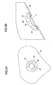
- FIGS. 2A, 2B show an alternative embodiment, which is opposite to the embodiment of FIGS. 1A, 1B in the realization of the liner differs.
- the intermediate layer in the execution of FIGS. 2A, 2B not continuous, but forms spatially limited connection surfaces 21 which are interrupted by empty areas 22.
- two part-circular areas, 21 of the intermediate layer are provided.
- the only partial connection of the membrane 30 along its circumference to the main layer 10 causes air to flow out of the outflow opening 11 through the outflow opening 11 and the empty regions 22 in each deployment state of the airbag chamber 1, for example into the environment or into a further airbag chamber.
- the membrane 30 which laterally overlaps the outflow opening 11 causes the membrane to assume the function of a sealing element when the flow direction is reversed.
- a check valve is provided which merely allows the flowing gas in one flow direction to pass through the discharge device or the valve formed thereby, while the gas in the other flow direction leads to closure of the valve.
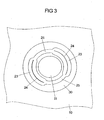
- FIG. 3 shows a combination of the embodiments of FIGS. 1A, 1B and 2A, 2B ,
- the intermediate layer 20 is continuous, ie it extends along the entire circumference of the membrane 30 between this and the main layer 11.
- at least one region 23 is provided which has means 24 which cause the membrane 30 in the considered Area 23 can not separate from the main layer 10.
- these additional means are a seam 24 which firmly connect the membrane 30 and the main ply 10 in the region 23 under consideration.
- two such holding portions 23 are provided, but also a different number of such portions 23 is possible.
- the interlayer further forms opening portions 25 located between the holding portions 23.
- the function of this example is as follows. When a minimum pressure is reached in the airbag chamber 1, the opening regions 25 open, while the membrane 30 along the holding regions 23 is still connected to the main layer 10. From a certain pressure is thus an overflow of gas in the environment or in another airbag chamber, wherein in addition to the functionality of the embodiment of FIG. 1 the functionality of a check valve is provided, ie in a reversal of the flow direction, the outflow opening 11 is closed by the membrane 30. It is thus realized a check valve, which opens only from a predetermined pressure.
- FIGS. 4A, 4B show an embodiment of a gas bag 100, which has at least two gas bag chambers 110, 120 shown schematically.
- these are two airbag chambers of a side airbag, namely a thorax chamber 110 and a head chamber 120.
- the second chamber 120 is filled by the first chamber 110 with gas.
- the gas bag wall 111 of the first chamber 110 forms a cylindrical extension 112, which is also referred to below as a snorkel and projects into a corresponding opening 122 of the wall 121 of the second airbag chamber 120.
- the snorkel 112 is made of a form unstable material, ie in the absence an internal pressure of the chord 122 coincides.
- the snorkel 112 preferably consists of the material of the gas bag wall 111.
- FIG. 4A shows the situation that in the first airbag chamber, a pressure prevails P1, which is greater than the pressure P2 in the second airbag chamber 120. Accordingly, gas flows through the snorkel 112 in the second airbag chamber 120. Due to the flow of gas and the associated internal pressure The snorkel 112 is straightened out and projects vertically up into the second airbag chamber 120.
- FIG. 4B shows the situation that the pressures P1, P2 in the two airbag chambers 110, 120 are substantially identical, the filling process of the second airbag chamber 120 is thus completed.
- the snorkel 112 is closed. Accordingly, a snorkel valve is provided which allows gas to flow only in one direction.
- the snorkel 112 similarly kinks when the pressure P2 in the second airbag chamber 120 is higher than the pressure P1 in the first airbag chamber 110, for example due to an impact of the occupant.
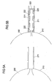
- FIGS. 5A, 5B show an example in which according to FIG. 5A an airbag chamber 200 in its wall 210 forms an outlet opening in the form of a tube 211, which is cylindrical and preferably dimensionally stable.
- the tube 211 consists of a material that shrinks when heated, so that the cross section of the tube 211 and thus the outflowing amount of gas are reduced when heated.
- the hose 211 is accordingly referred to below as a sock hose 211.
- FIG. 5B One possible application of a sock hose 211 for controlling the flow of a gas quantity is shown in FIG. 5B ,
- a sock tube 211 Within the sock tube 211 is a sleeve 220 having side wall portions 221 which are interrupted by openings 222.
- the gas bag chamber 200 facing away from end face 223 of the sleeve 220 is closed.
- outflowing gas can flow through the lateral openings 222 to the outside. Since the outflowing gas of a vehicle occupant restraint system usually has a high temperature, the sock hose 211 shrinks increasingly as it flows through the hot gas.
- the socking hose 211 comes to bear against the outside of the sleeve 220.
- gas can no longer escape through the lateral openings 222 of the sleeve 220.
- the gas flow thus decreases progressively and comes to a complete halt when the sock hose 211 abuts the wall of the sleeve 220 due to the shrinkage process.
- FIGS. 6A, 6B show an example in which an exhaust device of a gas bag chamber is controlled by means of a tether.
- An airbag chamber 300 has in its gas bag wall 310 an outflow opening 311.
- the outflow opening 311 allows gas to escape into the surroundings of the airbag or a further airbag chamber.
- Above the outflow opening 311 is a flat tether 320, whose two ends 322, 323 are fixedly attached to the gas bag wall 310.
- loops 330 are provided on the gas bag wall, through which the tether 320 is threaded adjacent to the outflow opening 320. In one of the loops 330 or elsewhere, the tether 320 is folded several times, so that there is a reservoir of tether material.
- the opening z321 of the tether 320 is disposed above the outflow opening 311 of the gas bag wall 310, so that at the beginning of a deployment of gas through the openings 321, 311, the airbag chamber 300 can flow out.
- the opening 321 of the tether 320 shifts relative to the discharge opening 311 of the gas bag wall 310, so that the initially existing match is eliminated.
- the tether 320 covers the outflow opening 311 and prevents further outflow of gas.
- the described embodiments of a gas bag for a vehicle occupant protection system allow a reduction in the occupant load in the event of triggering by exhaust devices, over which the amount of the outflowing gas is controllable.
Landscapes
- Engineering & Computer Science (AREA)
- Mechanical Engineering (AREA)
- Air Bags (AREA)
Claims (7)
- Coussin à gaz pour un système de retenue de passagers dans un véhicule, comprenant au moins une chambre de coussin susceptible d'être remplie avec du gaz, qui présente au moins un dispositif d'échappement via lequel le gaz peut s'échapper hors de la chambre de coussin, dans lequel- le dispositif d'échappement comprend un prolongement de forme tubulaire (112) qui est réalisé dans la paroi (111) de la chambre de coussin (110) et constitue une ouverture d'échappement pour la chambre de coussin (110),- le coussin à gaz (100) comprend au moins une première chambre de coussin (110) et une seconde chambre de coussin (120), le prolongement de forme tubulaire (112) étant réalisé sur la première chambre de coussin (110) et pénétrant dans la seconde chambre de coussin (120),caractérisé en ce que- le coussin à gaz est réalisé de telle façon que, dans le cas d'un déclenchement, la seconde chambre de coussin (120) est remplie avec du gaz exclusivement via la première chambre de coussin (110) au moyen du prolongement tubulaire (112) qui pénètre dans la seconde chambre de coussin (120), et- le prolongement tubulaire (112) est de forme flexible en ce sens que, lorsqu'aucun gaz ne le traverse, il se replie dans la seconde chambre du coussin, de telle manière que- le prolongement tubulaire (112) représente une valve qui ne permet un passage du gaz que dans une direction, à savoir en direction de la seconde chambre de coussin (120).
- Coussin à gaz selon la revendication 1, caractérisé en ce que la première chambre de coussin (110) et la seconde chambre de coussin (120) sont agencées l'une au-dessus de l'autre, et le prolongement tubulaire (112) pénètre verticalement vers le haut dans la seconde chambre de coussin (120) lorsqu'il est traversé par le gaz.
- Coussin à gaz selon la revendication 1 ou 2, caractérisé en ce que les deux chambres de coussin (110, 120) sont deux chambres de coussin d'un airbag latéral.
- Coussin à gaz selon la revendication 3, caractérisé en ce que les deux chambres de coussin (110, 120) constituent une chambre de thorax (110) et une chambre de tête (120) d'un airbag latéral.
- Coussin à gaz selon l'une des revendications 1 à 4, caractérisé en ce que le prolongement tubulaire (112) est de forme cylindrique.
- Coussin à gaz selon l'une des revendications 1 à 5, caractérisé en ce que le prolongement tubulaire (112) est formé du matériau de la paroi (111) de coussin à gaz.
- Coussin à gaz selon l'une des revendications 1 à 6, caractérisé en ce que le coussin à gaz est réalisé de telle façon que, en cas de déclenchement, la seconde chambre de coussin (120) est remplie avec du gaz via la première chambre de coussin (110) au moyen du prolongement tubulaire (112) qui pénètre dans la seconde chambre de coussin (120) aussi longtemps que les pressions dans les deux chambres de coussin (110, 120) soient sensiblement identiques ou bien que la pression dans la seconde chambre de coussin (120) soit supérieure à la pression dans la première chambre de coussin (110), suite à quoi le prolongement tubulaire (112) se replie dans la seconde chambre de coussin (120).
Applications Claiming Priority (2)
| Application Number | Priority Date | Filing Date | Title |
|---|---|---|---|
| DE102005034250A DE102005034250A1 (de) | 2005-07-18 | 2005-07-18 | Gassack für ein Fahrzeuginsassen-Rückhaltesystem |
| PCT/DE2006/001182 WO2007009427A2 (fr) | 2005-07-18 | 2006-07-04 | Sac gonflable pour systeme de retenue de passagers de vehicule |
Publications (2)
| Publication Number | Publication Date |
|---|---|
| EP1907242A2 EP1907242A2 (fr) | 2008-04-09 |
| EP1907242B1 true EP1907242B1 (fr) | 2010-05-19 |
Family
ID=37084870
Family Applications (1)
| Application Number | Title | Priority Date | Filing Date |
|---|---|---|---|
| EP06761784A Not-in-force EP1907242B1 (fr) | 2005-07-18 | 2006-07-04 | Sac gonflable pour systeme de retenue de passagers de vehicule |
Country Status (6)
| Country | Link |
|---|---|
| US (1) | US20080179867A1 (fr) |
| EP (1) | EP1907242B1 (fr) |
| JP (1) | JP2009501659A (fr) |
| CN (1) | CN101253076B (fr) |
| DE (2) | DE102005034250A1 (fr) |
| WO (1) | WO2007009427A2 (fr) |
Families Citing this family (24)
| Publication number | Priority date | Publication date | Assignee | Title |
|---|---|---|---|---|
| US8020889B2 (en) | 2005-09-21 | 2011-09-20 | Tk Holdings, Inc. | Passive airbag venting |
| WO2008122346A1 (fr) | 2007-04-09 | 2008-10-16 | Autoliv Development Ab | Coussin de sécurité gonflable destiné à protéger l'occupant d'un véhicule |
| DE202007007356U1 (de) * | 2007-05-22 | 2007-10-04 | Takata-Petri Ag | Gassackanordnung |
| KR100980931B1 (ko) * | 2007-12-15 | 2010-09-07 | 기아자동차주식회사 | 가변 인너벤트홀을 구비한 에어백쿠션 구조 |
| DE102008015731A1 (de) * | 2008-03-26 | 2009-10-08 | Schreiner Group Gmbh & Co. Kg | Airbagmantelelement |
| DE102009005696A1 (de) | 2009-01-19 | 2009-10-08 | Takata-Petri Ag | Fahrzeuginsassen-Rückhaltesystem mit einem aufblasbaren Gassack |
| DE102009005835B4 (de) | 2009-01-21 | 2017-12-07 | TAKATA Aktiengesellschaft | Gassackanordnung für ein Fahrzeuginsassen-Rückhaltesystem |
| DE102009005834A1 (de) * | 2009-01-21 | 2009-06-04 | Takata-Petri Ag | Gassack für ein Fahrzeuginsassen-Rückhaltesystem und Verfahren zum Herstellen eines Gassacks |
| USPP21525P3 (en) * | 2009-03-26 | 2010-11-23 | Gartenbau Und Spezialkulturen Westhoff Gbr | Variety of Calibrachoa plant named ‘Wescadobl’ |
| DE102009053381A1 (de) | 2009-11-14 | 2011-05-19 | Volkswagen Ag | Insassenschutzvorrichtung für ein Fahrzeug, insbesondere für ein Kraftfahrzeug, sowie Verfahren zum Steuern einer Insassenschutzvorrichtung |
| US9862350B2 (en) | 2013-08-12 | 2018-01-09 | Tk Holdings Inc. | Dual chambered passenger airbag |
| CN105555619B (zh) * | 2013-08-12 | 2019-05-28 | Tk控股公司 | 双腔室式乘客安全气囊 |
| US9376084B2 (en) | 2013-12-07 | 2016-06-28 | Autoliv Asp, Inc. | Multi-chamber airbags |
| DE112015000442T5 (de) | 2014-01-21 | 2016-12-01 | Tk Holdings Inc. | Insassenseitenairbag |
| US9340176B2 (en) | 2014-03-13 | 2016-05-17 | Ford Global Technologies, Llc | Passenger airbag with secondary chamber |
| US9150186B1 (en) | 2014-03-13 | 2015-10-06 | Ford Global Technologies, Llc | Passenger airbag with secondary chamber |
| US9580039B2 (en) | 2014-04-22 | 2017-02-28 | Autoliv Asp, Inc. | Multi-chamber airbag with unidirectional vent |
| US9248799B2 (en) | 2014-06-03 | 2016-02-02 | Autoliv Asp, Inc. | Dual cushion airbag with independent inflation |
| US9272684B1 (en) | 2014-10-10 | 2016-03-01 | Autoliv Asp, Inc. | Multi-chamber airbag with pinch valve |
| JP2016153262A (ja) * | 2015-02-20 | 2016-08-25 | オートリブ ディベロップメント エービー | エアバッグ装置 |
| US9533652B1 (en) | 2015-07-14 | 2017-01-03 | Autoliv Asp, Inc. | One-directional valve for multi-chamber airbags |
| US10293777B2 (en) | 2016-08-26 | 2019-05-21 | Autoliv Asp, Inc. | Multi-cushion airbag assemblies for reducing rotational velocity of an occupant's head |
| DE102019107366A1 (de) | 2019-03-22 | 2020-09-24 | Trw Automotive Gmbh | Gassackmodul |
| US11091111B2 (en) | 2019-10-01 | 2021-08-17 | Ford Global Technologies, Llc | Side airbag including lower lobe and upper lobe |
Family Cites Families (37)
| Publication number | Priority date | Publication date | Assignee | Title |
|---|---|---|---|---|
| US3324656A (en) * | 1964-05-04 | 1967-06-13 | Thiokol Chemical Corp | Temperature controlled igniter |
| US3474824A (en) * | 1968-01-17 | 1969-10-28 | Deere & Co | Dump valve for hydraulic control system |
| US3527475A (en) * | 1969-03-07 | 1970-09-08 | Eaton Yale & Towne | Vehicle safety system |
| JP2783849B2 (ja) * | 1989-07-14 | 1998-08-06 | タカタ株式会社 | エアバッグ装置におけるエアバッグ |
| DE4101287A1 (de) * | 1991-01-17 | 1992-07-30 | Trw Repa Gmbh | Aufblasbarer gassack fuer ein rueckhaltesystem in fahrzeugen |
| US5246250A (en) * | 1992-11-25 | 1993-09-21 | General Motors Corporation | Air bag valve assembly |
| US5280953A (en) * | 1992-11-25 | 1994-01-25 | General Motors Corporation | Displacement responsive air bag vent |
| US5478111A (en) * | 1993-08-11 | 1995-12-26 | Morton International, Inc. | Dynamic burn vents for the cushion of an air bag module |
| US5839755A (en) * | 1994-03-03 | 1998-11-24 | Trw Vehicle Safety Systems Inc. | Method and apparatus for restraining a vehicle occupant |
| DE19522765A1 (de) * | 1995-06-27 | 1997-01-02 | Pars Passive Rueckhaltesysteme | Airbagmodul |
| US5603526A (en) * | 1996-01-16 | 1997-02-18 | Morton International, Inc. | Pressure vent for air bag cushion |
| US5718450A (en) * | 1996-01-19 | 1998-02-17 | Takata, Inc. | Inflatable restraint system having a head/thorax cushion for side impact protection |
| JPH1076908A (ja) * | 1996-09-06 | 1998-03-24 | Bridgestone Corp | エアバッグ |
| DE19640322B4 (de) * | 1996-09-19 | 2005-06-30 | Takata-Petri Ag | Airbagmodul |
| US5791685A (en) * | 1997-02-20 | 1998-08-11 | Alliedsignal Inc. | Three-chambered side impact air bag |
| US5833265A (en) * | 1997-02-21 | 1998-11-10 | Takata, Inc. | Airbag with excursion restrictors |
| US5803121A (en) * | 1997-04-17 | 1998-09-08 | Chrysler Corporation | Air bag venting system |
| JP3331909B2 (ja) * | 1997-06-10 | 2002-10-07 | トヨタ自動車株式会社 | 胸部頭部一体式エアバッグ装置 |
| US6017057A (en) * | 1998-03-13 | 2000-01-25 | Trw Inc. | Inflatable vehicle occupant protection device |
| DE19930155A1 (de) * | 1999-06-30 | 2001-01-04 | Takata Europ Gmbh | Rückschlagventil für eine Luftsack |
| LU90431B1 (de) * | 1999-08-31 | 2001-03-01 | Iee Sarl | Vorrichtung zum gesteuerten Entlueften eines Gassacks |
| JP3900765B2 (ja) * | 1999-12-08 | 2007-04-04 | タカタ株式会社 | エアバッグ装置 |
| DE10018170B4 (de) * | 2000-04-12 | 2012-10-31 | Audi Ag | Luftsackanordnung |
| US6447006B1 (en) * | 2000-10-03 | 2002-09-10 | Autoliv Asp, Inc. | Inflatable curtain cushion vent |
| DE10059956C2 (de) * | 2000-12-02 | 2002-10-31 | Autoliv Dev | Gassack mit einer in ihrem Öffnungsquerschnitt geregelten Abströmöffnung |
| DE10111566B4 (de) * | 2001-03-10 | 2005-11-17 | Daimlerchrysler Ag | Sicherheitsvorrichtung für ein Kraftfahrzeug |
| US6722695B2 (en) * | 2001-03-29 | 2004-04-20 | Toyoda Gosei, Co., Ltd. | Airbag and method for manufacturing the airbag |
| JP3987732B2 (ja) * | 2002-01-31 | 2007-10-10 | 本田技研工業株式会社 | エアバッグ装置 |
| JP2003327071A (ja) * | 2002-05-10 | 2003-11-19 | Takata Corp | エアバッグ及びエアバッグ装置 |
| DE20209659U1 (de) * | 2002-06-21 | 2002-10-31 | TRW Automotive Safety Systems GmbH & Co. KG, 63743 Aschaffenburg | Gassack |
| US6832778B2 (en) * | 2002-07-19 | 2004-12-21 | Delphi Technologies, Inc. | Air bag restraint including selectively operable venting elements |
| US6773030B2 (en) * | 2002-07-24 | 2004-08-10 | Trw Vehicle Safety Systems Inc. | Air bag with vent |
| DE10236859A1 (de) * | 2002-08-07 | 2004-02-19 | Takata Corp. | Gassack für ein Airbagmodul |
| GB2394919B (en) * | 2002-11-06 | 2006-01-25 | Autoliv Dev | Improvements in or relating to an air-bag arrangement |
| JP2004243976A (ja) * | 2003-02-17 | 2004-09-02 | Takata Corp | 側突用エアバッグ装置 |
| US7401811B2 (en) * | 2003-09-10 | 2008-07-22 | Honda Motor Co., Ltd. | Airbag device |
| DE202005001000U1 (de) * | 2005-01-21 | 2005-06-02 | Trw Automotive Safety Systems Gmbh | Gassackmodul für eine Fahrzeuginsassen-Rückhaltevorrichtung |
-
2005
- 2005-07-18 DE DE102005034250A patent/DE102005034250A1/de not_active Ceased
-
2006
- 2006-07-04 JP JP2008521792A patent/JP2009501659A/ja not_active Ceased
- 2006-07-04 DE DE502006006991T patent/DE502006006991D1/de active Active
- 2006-07-04 WO PCT/DE2006/001182 patent/WO2007009427A2/fr active Application Filing
- 2006-07-04 CN CN2006800263956A patent/CN101253076B/zh not_active Expired - Fee Related
- 2006-07-04 EP EP06761784A patent/EP1907242B1/fr not_active Not-in-force
-
2008
- 2008-01-17 US US12/007,988 patent/US20080179867A1/en not_active Abandoned
Also Published As
| Publication number | Publication date |
|---|---|
| US20080179867A1 (en) | 2008-07-31 |
| CN101253076A (zh) | 2008-08-27 |
| WO2007009427A2 (fr) | 2007-01-25 |
| EP1907242A2 (fr) | 2008-04-09 |
| WO2007009427A3 (fr) | 2007-06-21 |
| JP2009501659A (ja) | 2009-01-22 |
| DE502006006991D1 (de) | 2010-07-01 |
| CN101253076B (zh) | 2012-11-07 |
| DE102005034250A1 (de) | 2007-02-01 |
Similar Documents
| Publication | Publication Date | Title |
|---|---|---|
| EP1907242B1 (fr) | Sac gonflable pour systeme de retenue de passagers de vehicule | |
| EP1391355B1 (fr) | Sac gonflable pour un module de sac de sécurité gonflable | |
| EP1848615B1 (fr) | Coussin gonflable et procede de fabrication d'un coussin gonflable | |
| EP1778525B1 (fr) | Sac a gaz pour le module airbag d'un vehicule a moteur | |
| EP1086861B1 (fr) | Dispositif de protection à sac gonflable | |
| EP2424750B1 (fr) | Module de coussin gonflable pour protéger la région du thorax et la tête d'un occupant de véhicule | |
| DE102004006185B4 (de) | Gassack zum Einbau in ein Kraftfahrzeug | |
| WO2007110167A1 (fr) | Airbag pour véhicules automobiles | |
| EP1817210B1 (fr) | Dispositif airbag lateral | |
| EP0878359B1 (fr) | Dispositif de protection contre le choc latéral pour occupant de véhicule | |
| EP2864160B1 (fr) | Ensemble airbag pour un système de retenue d'un occupant de véhicule automobile | |
| EP1686016B1 (fr) | Coussin gonflable avec trou d'évent | |
| DE19605620B4 (de) | Den Thoraxbereich entlastendes Seitenairbagmodul und Gassack hierfür | |
| EP2105357B1 (fr) | Elément d'enveloppe d'airbag | |
| DE102008032981A1 (de) | Fahrzeugsitzanordnung | |
| EP2387518A1 (fr) | Système de retenue d'occupant de véhicule à sac à gaz gonflable | |
| DE102012220983B4 (de) | Gassackanordnung für ein Fahrzeuginsassen-Rückhaltesystem | |
| DE102013113434B4 (de) | Gassackmodul mit einer eine Aufspringfalte aufweisenden Venteinrichtung | |
| DE102006031664B4 (de) | Aufblasbare Fahrzeuginsassenschutzeinrichtung | |
| DE102019132199A1 (de) | Gassack für ein Fahrzeuginsassen-Rückhaltesystem | |
| WO2008000340A1 (fr) | Coussin gonflable ainsi que procédé de fabrication d'un coussin gonflable | |
| WO2024110284A1 (fr) | Airbag doté d'un dispositif de ventilation actif | |
| EP3169554B1 (fr) | Coussin gonflable pour un système de retenue de l'occupant de véhicule |
Legal Events
| Date | Code | Title | Description |
|---|---|---|---|
| PUAI | Public reference made under article 153(3) epc to a published international application that has entered the european phase |
Free format text: ORIGINAL CODE: 0009012 |
|
| 17P | Request for examination filed |
Effective date: 20080218 |
|
| AK | Designated contracting states |
Kind code of ref document: A2 Designated state(s): DE FR GB SE |
|
| RBV | Designated contracting states (corrected) |
Designated state(s): DE FR GB SE |
|
| GRAP | Despatch of communication of intention to grant a patent |
Free format text: ORIGINAL CODE: EPIDOSNIGR1 |
|
| GRAS | Grant fee paid |
Free format text: ORIGINAL CODE: EPIDOSNIGR3 |
|
| GRAA | (expected) grant |
Free format text: ORIGINAL CODE: 0009210 |
|
| AK | Designated contracting states |
Kind code of ref document: B1 Designated state(s): DE FR GB SE |
|
| REG | Reference to a national code |
Ref country code: GB Ref legal event code: FG4D Free format text: NOT ENGLISH |
|
| REF | Corresponds to: |
Ref document number: 502006006991 Country of ref document: DE Date of ref document: 20100701 Kind code of ref document: P |
|
| PG25 | Lapsed in a contracting state [announced via postgrant information from national office to epo] |
Ref country code: SE Free format text: LAPSE BECAUSE OF FAILURE TO SUBMIT A TRANSLATION OF THE DESCRIPTION OR TO PAY THE FEE WITHIN THE PRESCRIBED TIME-LIMIT Effective date: 20100519 |
|
| PLBE | No opposition filed within time limit |
Free format text: ORIGINAL CODE: 0009261 |
|
| STAA | Information on the status of an ep patent application or granted ep patent |
Free format text: STATUS: NO OPPOSITION FILED WITHIN TIME LIMIT |
|
| 26N | No opposition filed |
Effective date: 20110222 |
|
| GBPC | Gb: european patent ceased through non-payment of renewal fee |
Effective date: 20100819 |
|
| REG | Reference to a national code |
Ref country code: DE Ref legal event code: R097 Ref document number: 502006006991 Country of ref document: DE Effective date: 20110221 |
|
| PG25 | Lapsed in a contracting state [announced via postgrant information from national office to epo] |
Ref country code: GB Free format text: LAPSE BECAUSE OF NON-PAYMENT OF DUE FEES Effective date: 20100819 |
|
| REG | Reference to a national code |
Ref country code: DE Ref legal event code: R082 Ref document number: 502006006991 Country of ref document: DE Representative=s name: MAIKOWSKI & NINNEMANN PATENTANWAELTE, DE |
|
| REG | Reference to a national code |
Ref country code: DE Ref legal event code: R081 Ref document number: 502006006991 Country of ref document: DE Owner name: TAKATA AKTIENGESELLSCHAFT, DE Free format text: FORMER OWNER: TAKATA-PETRI AG, 63743 ASCHAFFENBURG, DE Effective date: 20120904 Ref country code: DE Ref legal event code: R082 Ref document number: 502006006991 Country of ref document: DE Representative=s name: MAIKOWSKI & NINNEMANN PATENTANWAELTE, DE Effective date: 20120904 Ref country code: DE Ref legal event code: R082 Ref document number: 502006006991 Country of ref document: DE Representative=s name: MAIKOWSKI & NINNEMANN PATENTANWAELTE PARTNERSC, DE Effective date: 20120904 Ref country code: DE Ref legal event code: R081 Ref document number: 502006006991 Country of ref document: DE Owner name: JOYSON SAFETY SYSTEMS GERMANY GMBH, DE Free format text: FORMER OWNER: TAKATA-PETRI AG, 63743 ASCHAFFENBURG, DE Effective date: 20120904 |
|
| PGFP | Annual fee paid to national office [announced via postgrant information from national office to epo] |
Ref country code: FR Payment date: 20130724 Year of fee payment: 8 |
|
| REG | Reference to a national code |
Ref country code: FR Ref legal event code: ST Effective date: 20150331 |
|
| PG25 | Lapsed in a contracting state [announced via postgrant information from national office to epo] |
Ref country code: FR Free format text: LAPSE BECAUSE OF NON-PAYMENT OF DUE FEES Effective date: 20140731 |
|
| REG | Reference to a national code |
Ref country code: DE Ref legal event code: R082 Ref document number: 502006006991 Country of ref document: DE Representative=s name: MAIKOWSKI & NINNEMANN PATENTANWAELTE PARTNERSC, DE Ref country code: DE Ref legal event code: R081 Ref document number: 502006006991 Country of ref document: DE Owner name: JOYSON SAFETY SYSTEMS GERMANY GMBH, DE Free format text: FORMER OWNER: TAKATA AKTIENGESELLSCHAFT, 63743 ASCHAFFENBURG, DE |
|
| PGFP | Annual fee paid to national office [announced via postgrant information from national office to epo] |
Ref country code: DE Payment date: 20190930 Year of fee payment: 14 |
|
| REG | Reference to a national code |
Ref country code: DE Ref legal event code: R119 Ref document number: 502006006991 Country of ref document: DE |
|
| PG25 | Lapsed in a contracting state [announced via postgrant information from national office to epo] |
Ref country code: DE Free format text: LAPSE BECAUSE OF NON-PAYMENT OF DUE FEES Effective date: 20210202 |