EP1906418A1 - Befehlsgerät mit Kontrollvorrichtung - Google Patents
Befehlsgerät mit Kontrollvorrichtung Download PDFInfo
- Publication number
- EP1906418A1 EP1906418A1 EP06020449A EP06020449A EP1906418A1 EP 1906418 A1 EP1906418 A1 EP 1906418A1 EP 06020449 A EP06020449 A EP 06020449A EP 06020449 A EP06020449 A EP 06020449A EP 1906418 A1 EP1906418 A1 EP 1906418A1
- Authority
- EP
- European Patent Office
- Prior art keywords
- control device
- actuating
- switching element
- mounting plate
- command device
- Prior art date
- Legal status (The legal status is an assumption and is not a legal conclusion. Google has not performed a legal analysis and makes no representation as to the accuracy of the status listed.)
- Granted
Links
Images


Classifications
-
- H—ELECTRICITY
- H01—ELECTRIC ELEMENTS
- H01H—ELECTRIC SWITCHES; RELAYS; SELECTORS; EMERGENCY PROTECTIVE DEVICES
- H01H3/00—Mechanisms for operating contacts
- H01H3/02—Operating parts, i.e. for operating driving mechanism by a mechanical force external to the switch
- H01H3/022—Emergency operating parts, e.g. for stop-switch in dangerous conditions
-
- H—ELECTRICITY
- H01—ELECTRIC ELEMENTS
- H01H—ELECTRIC SWITCHES; RELAYS; SELECTORS; EMERGENCY PROTECTIVE DEVICES
- H01H13/00—Switches having rectilinearly-movable operating part or parts adapted for pushing or pulling in one direction only, e.g. push-button switch
- H01H13/50—Switches having rectilinearly-movable operating part or parts adapted for pushing or pulling in one direction only, e.g. push-button switch having a single operating member
- H01H13/503—Stacked switches
Definitions
- the invention relates to a control device with control device, wherein the control device comprises an actuating element and a fastening element, wherein the fastening element is provided for attachment to a first mounting plate and / or to an operating unit mounted on the first mounting plate, wherein the actuating element for actuating one on a second Mounting plate mounted first switching element is provided, wherein the mounted on the first mounting plate operating unit is provided with proper assembly without control device for actuating the first switching element by means of an actuating plunger. Furthermore, the invention relates to a control device for a command device.
- the command device may be a command switch, for example an emergency stop switch, which has a pot-shaped or mushroom-shaped cap as an actuator.
- the cap or actuator is fixedly connected to the actuating tappet, e.g. screwed. If the command device is actuated, the actuating tappet of the command device is brought from the rest position to the actuated position.
- the actuating plunger inevitably interrupts the contacts of at least one NC switching element, so that the associated circuit is interrupted, for example, a connected electrical machine.
- openers and / or closer switching elements can be mounted, which are actuated together via the actuating plunger.
- command device and its control part usually work according to the principle of forced operation or forced opening.
- the switching state of the switching elements can also be interrogated by a monitoring device, for example by coupling in a bit pattern via the closed NC contacts of an NC switching element and continuously checking the received result.
- a monitoring device is, for example, the ASI-F monitoring device from Siemens. This device is also bus-capable, so that in the absence of the expected bit pattern via a bus data technically achievable plant parts can be brought into a safe state.
- the command device is also designed in two parts.
- the separability is required to attach the command device, for example, to a cabinet door, front panel or panel.
- an actuating unit for mounting through a relatively small hole in a cabinet door or the like out and connected by means of a fastening nut or a clamping ring with this.
- the actuating plunger on the actuator usually by means of a snap or screw, be attached.
- the voltage-carrying parts that are used in the switching elements can be safely installed or accommodated within the control cabinet.
- the command device is divided into an actuating unit and a switching unit, which can be installed separately, but must be brought together in a spatially precise manner for optimal operation.
- Out DE 103 48 884 is a command device is known in which a spatial assignment is monitored by a mounted on the actuator transponder and a corresponding reading unit on the device.
- a fuse element for a command device is known, which is a sealable additional part, wherein the sealable additional part is located behind the cabinet door or inside a housing and is unsuitable for a visual or mechanical control.
- the invention has for its object to provide a control device for a command device, which allows a safe and cost-effective manner, a function control of the command device.
- the invention is further based on the finding that transponder-based solutions are quite complex and therefore cost-intensive.
- the object of the invention is achieved with a command device of the type mentioned above, wherein at the proper assembly of the control device by means of the actuating plunger, at least a second switching element is actuated and at the same time the first switching element is actuated by means of the actuating element. Furthermore, the object is achieved by a control device according to claim 10.
- the control device which is provided for use in a command device, an actuating element and a fastening element.
- the operating unit which is often called simply actuator, on a first mounting plate mounted, wherein the fastening element of the control device, here depending on the position of the component to be controlled, on the mounting plate and / or on the attached actuator can be fastened.
- the components of the actuating unit which do not participate in the actuation movement of the actuator.
- the command device has at least one first switching element which is fastened on a second mounting plate.
- This first switching element optionally together with other switching elements forms the second part of the command device.
- the actuator transmits the actuating movement to the actuating tappet.
- the actuating tappet in turn is provided for actuating the first and a second and / or the optionally existing further switching elements.
- the first switching element is actuated permanently by means of the actuating element of the control device.
- the second or optionally existing further switching elements remain operable by the actuating plunger.
- the first switching element is assigned a new function, namely the function control of the installed command device.
- a mounting error of the actuating unit in the first mounting plate or the switching elements on the second mounting plate and an unwanted position of the mounting plates to each other are thus detectable by means of the first switching element.
- malfunctions that occur during use of the command device such as a deposition by shaking, detectable.
- control device can be used in conventional command devices, since an already existing in the command device switching element for position control in conjunction with the control device is used.
- the first switching element controls a circuit connected to the Detection of an error is used. This can be done for example by an optical signal, so that the user can immediately recognize whether the command device is ready for use or not functional.
- the first switching element is provided for opening and closing a control circuit, so that a multiple application is possible.
- control device for detecting the relative position of at least the second switching element to the operating unit, the function control of the command device and / or for installation control of the command device is provided.
- the control extends to the installation phase and the use phase of the command device.
- positions of components that are not part of the control device verifiable. This guarantees the fitter and the user optimal safety conditions.
- control device is designed in two parts, wherein a first part is a first fastening part and a second part is a second fastening part.
- the operating depth of the control device is variable, which, for example, the use in differently sized control devices is possible, or the dimensions of the housing can be taken into account by the distances of the switching elements of the actuator is variable.
- the first and / or the second mounting plate are each fastened to a first or second housing part or each form at least a first and / or a second housing part.
- it makes sense to install the command device directly into the housing, which saves components and material.
- it is with more complex devices makes sense to install the command device by means of at least one mounting plate, so that the housing choice remains flexible.
- FIG 1 and FIG 2 show an installed emergency stop switch 1 with a control device 9, wherein the emergency stop switch 1 is actuated in FIG 1 unactuated and in FIG.
- the control device 9 which has an actuating element 16 and a fastening element 17.
- the actuator 16 holds the switching element slider 11 in the actuated position.
- the associated first switching element 6 is thus provided for function or position control and indicates a proper mounting of the emergency stop switch 1 on.
- the actuating plunger 10 is connected to the actuator 2 directly, for example via a screw, so that via the actuator 2, a second Switching element 8 and a third switching element 7 via the switching element slide 13, 12 are actuated.
- the actuating tappet 10 is also provided for operating the switching element slider 11 of the first switching element 6, the switching state of the first switching element 6 is not changed during the actuating operation.
- the switching elements 6, 8, 7 are snapped or screwed in the lower housing part 4.
- the actuation of the switching element 6 by the actuator 16 of the control device 9 is also given only if a proper mounting of the switching units, which are usually installed as a block, the operating unit and the housing plates 4, 5 are present.
- the first housing part is designed as a housing upper part 5.
- the second housing part is designed as a lower housing part 4. It makes sense that the control device 9 is attached by means of the fastening element 17 on the guide 18, which belong to the non-movable elements of the emergency stop switch 1.
- the actuating unit is fastened to the upper housing part 5 by means of a fastening part 3, such as a ring nut.
- control device 9 may be part of the actuating device, the actuator 2, the fastening part 3, the upper housing part 5 or a separate part.
- the control device 9 is connected in accordance with the respective components mentioned and does not affect the positive actuation movement of the switching element slide 12, 13.
- the embodiment represents a particularly reliable and economical solution, since it is mechanical and manages without monitoring by an evaluation. Furthermore, a corresponding control device in other command devices, such as in push buttons, selectors or similar switches applicable. Furthermore, it is up to the user whether he wants to work with normally closed or normally open switching elements or a combination of both. This applies both to the first switching element 6, as well as for the second and third switching element 7,8.
- the control circuit which is switched by the first switching element 6 can also be used very variably.
- the corresponding signal can be implemented as desired in terms of tax, it being possible to use acoustic and / or visual alarms or even to shut down the system.
- a message to a control center is also easy to implement by means of the control circuit.
- a mechanical orientation or security against incorrect assembly of the modular control device or its installation can be used within a housing.
- FIG 3 shows the emergency stop switch 1 of FIG 1 in an assembled state.
- the actuating unit and the switching elements 6, 8, 7 are already installed on the upper housing part 5 or on the lower housing part 4. It can be seen that the proper installation, which also includes the proper connection of the housing parts 4, 5, the necessary spatial association between actuator unit and the switching elements 7, 8, 6 entails.
- control device 9 and the switching point of the first switching element 6 are tuned so that the signal of the first switching element 6 is generated before the actuator has moved so far from the switching elements 7, 8, that they no longer properly in an emergency, for example would be pressing.
- the signal of the mechanical switching element 6 can easily be processed by conventional controls, as they are common in simple machines or equipment.
- the first switching element 6 can be connected to other contacts of the controller as desired in parallel or in series to initiate the necessary measures (for example, stop, alarm) in the case of signaling.
- other types of mechanical contacts such as micro-switches
- the upper housing part 5 which is designed for example as a cabinet door and carries a plurality of command devices, all or more actuators monitored with a control device 9 and the associated monitoring switching element, thus ensuring that even with unilateral opening of the cabinet door an incorrect assignment of actuator units and the associated switching elements is detected.
- the circuit is reliably interrupted and remains interrupted if a positively-opening switching element 6 is used.
- the spatial separation is detectable, but also an incorrect or changed assignment of the switching elements to the associated operating units can be reconstructed, which would be detectable, for example, a warped cabinet door.
- control device 9 is provided as a separate part to keep the actuator unit in the event of unwanted detachment of the upper housing part 5 at least in the upper housing part 5, although the proper position is no longer given.
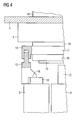
- FIG 4 shows a two-part running control device that can replace the control device 9 of the emergency stop switch 1 of FIG 1.
- the control device consists of two parts, wherein a first fastening part 14, the fastening element 17 and a second fastening part 15 has the actuating element 16. Both parts can be pushed into each other, with different connections for the two-part solution are conceivable.
- the first fastening part 14 and the second fastening part 15 are mutually adjustable, for example by an adjusting screw, which is not shown, wherein the distance of the two parts of the triggering time of the first switching element 6 in the event of detachment of the operating unit can be fixed. It is also conceivable that by a flexible length adjustment, the switching elements 6,7,8 can take a different operational relative position to the operating unit.
- a self-adjustment of the first and second fastening part 14, 15 to each other is provided.
- a latch provided with appropriate force during installation to determine the distance between the two parts.
- the restoring force which acts on the second fastening part 15 by the switching element slider 11, is insufficient to further introduce the second fastening part 15 into the first fastening part 14.
- other fastening mechanisms that allow insertion of the second fastening part 15 into the first fastening part 14, but prevent the removal of the first fastening part 14 from the second fastening part 15 after insertion, for example in connection with barbs.
- the invention relates to a control device with control device, wherein the control device comprises an actuating element and a fastening element.
- the command device is designed in two parts and has an actuating unit and switching elements. The required spatial allocation between actuator and switching elements should be monitored in a cost effective and safe way. For this purpose, with proper assembly of the control device by means of an actuator at least a second switching element operable and simultaneously actuates a first switching element by means of the actuating element of the control device.
Abstract
Description
- Die Erfindung betrifft ein Befehlsgerät mit Kontrollvorrichtung, wobei die Kontrollvorrichtung ein Betätigungselement und ein Befestigungselement aufweist, wobei das Befestigungselement zur Befestigung an eine erste Montageplatte und/oder an eine auf der ersten Montageplatte befestigten Betätigungseinheit vorgesehen ist, wobei das Betätigungselement zur Betätigung eines auf einer zweiten Montageplatte befestigten ersten Schaltelementes vorgesehen ist, wobei die auf der ersten Montageplatte befestigte Betätigungseinheit bei ordnungsgemäßer Montage ohne Kontrollvorrichtung zur Betätigung des ersten Schaltelements mittels eines Betätigungsstößels vorgesehen ist. Weiter betrifft die Erfindung eine Kontrollvorrichtung für ein Befehlsgerät.
- Das Befehlsgerät kann ein Befehlsschalter, beispielsweise ein Not-Aus-Schalter sein, welcher eine topfförmige oder pilzförmige Kappe als Betätiger aufweist. Aus Sicherheitsgründen ist die Kappe bzw. der Betätiger mit dem Betätigungsstößel fest verbunden, z.B. verschraubt. Wird das Befehlsgerät betätigt, so wird der Betätigungsstößel des Befehlsgerätes von der Ruhestellung in die Betätigungsstellung gebracht. Der Betätigungsstößel unterbricht dabei zwangsläufig die Kontakte mindestens eines Öffnerschaltelements, so dass der zugehörige Stromkreis zum Beispiel einer angeschlossenen elektrischen Maschine unterbrochen wird. Darüber hinaus können je nach Anwendungsfall auch Öffner und/oder Schließerschaltelemente angebracht sein, welche gemeinsam über den Betätigungsstößel betätigt werden.
- Aus Sicherheitsgründen funktionieren das Befehlsgerät und sein Stellteil in der Regel nach dem Prinzip der Zwangsbetätigung, bzw. der Zwangsöffnung.
- Der Schaltzustand der Schaltelemente kann alternativ auch durch ein Überwachungsgerät abgefragt werden, indem zum Beispiel ein Bitmuster über die geschlossene Öffnerkontakte eines Öffnerschaltelements eingekoppelt wird und fortlaufend das empfangene Ergebnis überprüft wird. Ein derartiges Überwachungsgerät ist zum Beispiel das ASI-F-Überwachungsgerät der Firma Siemens. Dieses Gerät ist zudem busfähig, so dass bei Ausbleiben des erwarteten Bitmusters über einen Bus datentechnisch erreichbare Anlagenteile in einen sicheren Zustand gebracht werden können.
- Das Befehlsgerät ist ferner zweiteilig ausgeführt. Die Trennbarkeit ist erforderlich, um das Befehlsgerät zum Beispiel an einer Schaltschranktür, Frontplatte oder Schalttafel befestigen zu können. Hierzu wird beispielsweise eine Betätigungseinheit zur Montage durch eine verhältnismäßig kleine Bohrung in einer Schaltschranktür oder ähnlichem geführt und mittels einer Befestigungsmutter oder eines Klemmrings mit dieser verbunden. Anschließend kann der Betätigungsstößel am Betätiger, üblicherweise mittels einer Schnapp- oder Schraubverbindung, befestigt werden. Die spannungstragenden Teile hingegen, die in den Schaltelementen Verwendung finden, können sicher innerhalb des Schaltschrankes installiert bzw. untergebracht werden. Das Befehlsgerät ist hierfür in eine Betätigungseinheit und eine Schalteinheit aufgeteilt, die separat installiert werden können, aber für eine optimale Funktionsweise räumlich präzise zusammengeführt werden müssen.
- Wird die Befestigung des Betätigungsstößels am Betätiger nicht ordnungsgemäß ausgeführt oder wird die Betätigungseinheit nicht korrekt platziert bzw. montiert, oder hat sich die Schraubverbindung des Betätigungsstößels durch Vibration gelöst, so ist die Betätigung zumindest eines Schaltelementes durch die Betätigungseinheit möglicherweise nicht mehr gewährleistet, ohne dass dies bemerkt wird. Ein Not-Aus-Stromkreis bleibt dann trotz Betätigung des Not-Aus-Schalters weiterhin geschlossen. Der Not-Aus-Schalter verliert somit seine Funktionsfähigkeit und damit seine Schutzfunktion. Dies gilt in entsprechender Weise auch für Befehlsgeräte im Allgemeinen. Dies kann in Steuerungsanlagen zu unabsehbaren Schäden an Mensch und Anlagenteilen führen.
- Aus
DE 103 48 884 ist ein Befehlsgerät bekannt, bei dem durch einen am Betätiger angebrachten Transponder und einer entsprechenden Leseeinheit am Gerät eine räumliche Zuordnung überwacht wird. - Aus der
DE 203 05 818 ist ein Sicherungselement für ein Befehlsgerät bekannt, bei dem es sich um ein plombierbares Zusatzteil handelt, wobei sich das plombierbare Zusatzteil hinter der Schaltschranktür oder im Innern eines Gehäuses befindet und für eine visuelle oder mechanische Kontrolle ungeeignet ist. - Der Erfindung liegt die Aufgabe zugrunde, eine Kontrollvorrichtung für ein Befehlsgerät anzugeben, welches auf sichere und kostengünstige Weise eine Funktionskontrolle des Befehlsgeräts zulässt.
- Der Erfindung liegt weiterhin die Erkenntnis zugrunde, dass transponderbasierende Lösungen recht aufwendig und deshalb kostenintensiv sind.
- Die Aufgabe der Erfindung wird gelöst mit einem Befehlsgerät der eingangs genannten Art, wobei bei ordnungsgemäßer Montage der Kontrollvorrichtung mittels des Betätigungsstößels mindestens ein zweites Schaltelement betätigbar ist und gleichzeitig das erste Schaltelement mittels des Betätigungselementes betätigt ist. Des Weiteren wird die Aufgabe durch eine Kontrollvorrichtung gemäß Anspruch 10 gelöst.
- Erfindungsgemäß weist die Kontrollvorrichtung, die zum Einsatz in ein Befehlsgerät vorgesehen ist, ein Betätigungselement und ein Befestigungselement auf. Aufgrund der zweiteiligen Ausführungen des Befehlsgerätes wird die Betätigungseinheit, die oft auch schlicht Betätiger genannt wird, auf einer ersten Montageplatte montiert, wobei das Befestigungselement der Kontrollvorrichtung, hier in Abhängigkeit der Position des zu kontrollierenden Bauteils, an der Montageplatte und/oder am befestigten Betätigungselement befestigbar ist. Für die Befestigung der Kontrollvorrichtung eignen sich insbesondere die Bauteile der Betätigungseinheit, die an der Betätigungsbewegung des Betätigers nicht teilhaben.
- Weiterhin weist das Befehlsgerät mindestens ein erstes Schaltelement auf, welches auf einer zweiten Montageplatte befestigt ist. Dieses erste Schaltelement bildet gegebenenfalls zusammen mit weiteren Schaltelementen den zweiten Teil des Befehlsgerätes. Wird der Betätiger des Befehlsgerätes durch den Benutzer betätigt, so überträgt der Betätiger die Betätigungsbewegung auf den Betätigungsstößel. Der Betätigungsstößel wiederum ist zur Betätigung des ersten und eines zweiten und/oder der gegebenenfalls vorhandenen weiteren Schaltelemente vorgesehen. Bei ordnungsgemäß montierter Kontrollvorrichtung wird das erste Schaltelement mittels des Betätigungselementes der Kontrollvorrichtung dauerhaft betätigt. Hierbei bleiben das zweite bzw. die gegebenenfalls vorhandenen weiteren Schaltelemente durch den Betätigungsstößel betätigbar. Das erste Schaltelement hingegen wird mit einer neuen Funktion belegt, nämlich der Funktionskontrolle des installierten Befehlsgerätes. Ein Montagefehler der Betätigungseinheit in der ersten Montageplatte oder der Schaltelemente auf der zweiten Montageplatte sowie eine ungewollte Position der Montageplatten zueinander sind somit mittels des ersten Schaltelementes detektierbar. Ebenso sind Funktionsfehler, die während der Benutzung des Befehlsgerätes auftreten, wie zum Beispiel eine Depositionierung durch Rüttelbewegung, detektierbar.
- Vorteilhafterweise ist die Kontrollvorrichtung in herkömmlichen Befehlsgeräten einsetzbar, da ein bereits im Befehlsgerät vorhandenes Schaltelement zur Positionskontrolle in Verbindung mit der Kontrollvorrichtung herangezogen wird. Das erste Schaltelement kontrolliert einen Stromkreis, der zur Erkennung eines Fehlers herangezogen wird. Dies kann beispielsweise durch ein optisches Signal geschehen, so dass der Benutzer auf Anhieb erkennen kann, ob das Befehlsgerät einsatzbereit bzw. nicht funktionstüchtig ist.
- In einer vorteilhaften Ausführungsform ist das erste Schaltelement zum Öffnen und Schließen eines Kontrollstromkreises vorgesehen, so dass eine Mehrfachanwendung möglich ist.
- Bei einer vorteilhaften Ausführungsform ist die Kontrollvorrichtung zur Erkennung der relativen Position mindestens des zweiten Schaltelements zur Betätigungseinheit, zur Funktionskontrolle des Befehlsgerätes und/oder zur Installationskontrolle des Befehlsgerätes vorgesehen. Somit erstreckt sich die Kontrolle auf die Installationsphase und auf die Benutzungsphase des Befehlsgeräts. Zudem sind auch Positionen von Bauteilen, die nicht zum Befehlsgerät gehören, überprüfbar. Dies garantiert dem Monteur und dem Benutzer optimale Sicherheitsbedingungen.
- Bei einer vorteilhaften Ausführungsform ist die Kontrollvorrichtung zweiteilig ausgeführt, wobei ein erster Teil ein erstes Befestigungsteil und ein zweiter Teil ein zweites Befestigungsteil ist. Bei einer zweiteiligen Ausführung ist die Betätigungstiefe der Kontrollvorrichtung variierbar, womit beispielsweise der Einsatz in unterschiedlich dimensionierten Befehlsgeräten möglich ist, oder auf die Dimensionen des Gehäuses Rücksicht genommen werden kann, indem die Entfernungen der Schaltelemente von der Betätigungseinheit variierbar ist.
- Bei einer vorteilhaften Ausführungsform sind die erste und/oder die zweite Montageplatte jeweils an einem ersten bzw. zweiten Gehäuseteil befestigbar oder bilden jeweils zumindest ein erstes und/oder ein zweites Gehäuseteil. Bei einfacheren Aufbauten ist es sinnvoll, das Befehlsgerät direkt in das Gehäuse zu installieren, wodurch Bauteile und Material gespart werden. Andererseits ist es bei komplexeren Geräten sinnvoll, das Befehlsgerät mittels mindestens einer Montageplatte einzubauen, so dass die Gehäusewahl flexibel bleibt.
- Weitere vorteilhafte Ausbildungen und bevorzugte Weiterbildungen der Erfindung sind der Figurenbeschreibung und/oder den Unteransprüchen zu entnehmen.
- Im Folgenden wird die Erfindung anhand der in den Figuren dargestellten Ausführungsbeispiele näher beschrieben und erläutert.
- Es zeigen:
- FIG 1
- einen installierten Not-Aus-Schalter mit Kontrollvorrichtung,
- FIG 2
- den Not-Aus-Schalter der FIG 1 im betätigten Zustand,
- FIG 3
- den Not-Aus-Schalter der FIG 1 in einem Montagezustand und
- FIG 4
- eine zweiteilig ausgeführte Kontrollvorrichtung in einem Not-Aus-Schalter.
- FIG 1 und FIG 2 zeigen einen installierten Not-Aus-Schalter 1 mit einer Kontrollvorrichtung 9, wobei der Not-Aus-Schalter 1 in FIG 1 unbetätigt und in FIG 2 betätigt ist.
- In beiden Figuren ist die Kontrollvorrichtung 9 abgebildet, die ein Betätigungselement 16 und ein Befestigungselement 17 aufweist. Das Betätigungselement 16 hält den Schaltelementschieber 11 in der betätigten Position. Das zugehörige erste Schaltelement 6 ist somit zur Funktions- bzw. Positionskontrolle vorgesehen und zeigt eine ordnungsgemäße Montage des Not-Aus-Schalters 1 an. Der Betätigungsstößel 10 ist mit dem Betätiger 2 direkt, beispielsweise über eine Schraubverbindung, verbunden, so dass über den Betätiger 2 ein zweites Schaltelement 8 und ein drittes Schaltelement 7 über deren Schaltelementschieber 13, 12 betätigbar sind. Obwohl der Betätigungsstößel 10 auch zur Betätigung des Schaltelementschiebers 11 des ersten Schaltelementes 6 vorgesehen ist, wird der Schaltzustand des ersten Schaltelementes 6 während des Betätigungsvorganges nicht geändert.
Bei gekapselten Befehlsgeräten, wie auch bei diesem Not-Aus-Schalter 1, sind die Schaltelemente 6, 8, 7 im Gehäuseunterteil 4 eingeschnappt oder eingeschraubt. - Die Betätigung des Schaltelementes 6 durch das Betätigungselement 16 der Kontrollvorrichtung 9 ist auch nur dann gegeben, wenn eine ordnungsgemäße Montage der Schalteinheiten, die in der Regel als Block installiert werden, der Betätigungseinheit und der Gehäuseplatten 4, 5 vorliegen.
- In diesem Ausführungsbeispiel ist das erste Gehäuseteil als Gehäuseoberteil 5 ausgeführt. Entsprechend ist das zweite Gehäuseteil als Gehäuseunterteil 4 ausgeführt. Sinnvollerweise ist die Kontrollvorrichtung 9 mittels des Befestigungselementes 17 an der Führung 18 angebracht, die zu den nicht bewegbaren Elementen des Not-Aus-Schalters 1 gehören. Die Betätigungseinheit ist mittels eines Befestigungsteils 3, wie beispielsweise einer Ringmutter, am Gehäuseoberteil 5 befestigt.
- Es ist gegebenenfalls von Vorteil für die Kontrollvorrichtung 9 als Bestandteil der Betätigungsvorrichtung, des Betätigers 2, des Befestigungsteils 3, des Gehäuseoberteiles 5 oder eines separaten Teiles zu sein. Die Kontrollvorrichtung 9 ist dabei mit den jeweils genannten Bauteilen entsprechend verbunden und beeinflusst die formschlüssige Betätigungsbewegung der Schaltelementschieber 12, 13 nicht.
- Vorteilhaft ist, dass keine speziellen Überwachungsschaltelemente erforderlich sind, sondern mit einem oder mehreren herkömmlichen, ohnehin vorhandenen Schaltelementen realisiert wird. Diese Eigenschaft ermöglicht ebenfalls die Nachrüstung von Befehlsgeräten in bestehenden Anlagen und Maschinen.
- Das Ausführungsbeispiel repräsentiert eine besonders zuverlässige und wirtschaftliche Lösung, da sie mechanisch ist und ohne eine Überwachung durch eine Auswerteelektronik auskommt. Weiterhin ist eine entsprechende Kontrollvorrichtung in anderen Befehlsgeräten, wie beispielsweise in Drucktastern, Wahlschaltern oder ähnlichen Schaltern anwendbar. Weiterhin bleibt es dem Benutzer überlassen, ob er mit Öffner- oder Schließerschaltelementen oder einer Kombination aus beiden arbeiten möchte. Dies gilt sowohl für das erste Schaltelement 6, sowie auch für das zweite und dritte Schaltelement 7,8.
- Der Kontrollstromkreis der durch das erste Schaltelement 6 geschaltet wird, kann ebenfalls sehr variabel verwendet werden. Das entsprechende Signal kann steuermäßig beliebig umgesetzt werden, wobei akustische und/oder optische Alarme verwendbar sind oder auch das Stillsetzen durchführbar wäre. Eine Meldung an eine Zentrale ist ebenso mittels des Kontrollstromkreises einfach zu realisieren.
- Vorteilhafterweise kann neben einer Realisierung einer zusätzlichen mechanischen form- oder kraftschlüssigen Sicherung durch die Kontrollvorrichtung 9 gegen Rütteln der Betätigungseinheit auch noch eine mechanische Orientierungshilfe bzw. Sicherung gegen falschen Zusammenbau des modular aufgebauten Befehlsgerätes bzw. dessen Installation innerhalb eines Gehäuses verwendet werden.
- FIG 3 zeigt den Not-Aus-Schalter 1 der FIG 1 in einem Montagezustand.
- Die Betätigungseinheit und die Schaltelemente 6, 8, 7 sind bereits auf dem Gehäuseoberteil 5 bzw. auf dem Gehäuseunterteil 4 installiert. Es ist zu erkennen, dass die ordnungsgemäße Installation, die auch die ordnungsgemäße Verbindung der Gehäuseteile 4, 5 einschließt, die erforderliche räumliche Zuordnung zwischen Betätigungseinheit und den Schaltelementen 7, 8, 6 nach sich zieht.
- Entfernt sich das Gehäuseoberteil 5 mit der darin montierten Betätigungseinheit (zum Beispiel in Folge sich lockernder Schrauben), so entfernt sich auch die Kontrollvorrichtung 9 vom ersten Schaltelement 6, welches die Funktion eines Überwachungsschaltelementes übernommen hat und gibt damit den Schaltelementschieber 11 im Gegensatz zu den vorangegangenen Figuren frei. Ab einer bestimmten Entfernung ändert das erste Schaltelement 6 seinen Schaltzustand. Ein Signal der Schaltzustandsänderung wird dann in einer Steuerung einer Maschine oder Anlage dazu benutzt werden, um einen sicheren Zustand herzustellen und/oder einen Alarm oder eine Meldung zu generieren.
- Vorteilhafterweise sind die Kontrollvorrichtung 9 und der Schaltpunkt des ersten Schaltelementes 6 so abgestimmt, dass das Signal des ersten Schaltelements 6 erzeugt wird, bevor sich die Betätigungseinheit so weit von den Schaltelementen 7, 8 entfernt hat, dass diese zum Beispiel im Notfall nicht mehr ordnungsgemäß zu betätigen wären.
- Im Gegensatz zu nicht mechanisch generierten Signalen (zum Beispiel eines Transponders) kann das Signal des mechanischen Schaltelementes 6 problemlos auch von konventionellen Steuerungen, wie sie bei einfachen Maschinen oder Anlagen üblich sind, verarbeitet werden. In diesem Sinne kann das erste Schaltelement 6 mit anderen Kontakten der Steuerung beliebig parallel oder in Reihe geschaltet werden, um im Falle der Signalgabe die notwendigen Maßnahmen (zum Beispiel Stillsetzen, Alarm) einzuleiten. In diesem Ausführungsbeispiel ist das erste Schaltelement 6 mit den anderen Schaltelementen 7, 8 baugleich, es können jedoch in weiteren Ausführungen auch andersartige mechanische Kontakte, wie zum Beispiel Mikroschalter, für die Überwachung der räumlichen Zuordnungen verwendet werden. Eine Kombination unterschiedlicher Schaltelemente ist dabei ebenfalls denkbar.
- Sind auf dem Gehäuseoberteil 5, welches beispielsweise als Schaltschranktür ausgeführt ist und mehrere Befehlsgeräte trägt, sämtliche oder mehrere Betätigungseinheiten mit einer Kontrollvorrichtung 9 und dem zugehörigen Überwachungsschaltelement überwachbar, somit wird sichergestellt, dass auch bei einseitigem Öffnen der Schaltschranktür eine nicht korrekte Zuordnung von Betätigungseinheiten und dem dazu gehörenden Schaltelementen detektiert wird.
- Zudem können unterschiedliche Alarme generiert werden, die eine Falschzuordnung oder eine Mehrfachfalschzuordnung detektieren. Die wohl simpelste Realisierung wäre vermutlich eine Reihenschaltung der überwachenden Schaltelemente, die die Auslösung eines (einzigen) Alarmsignals bei einer irgendeiner Falschzuordnung nach sicht zieht. Eine Erkennung bestimmter Falschzuordnungen ist mittels unterschiedlicher Alarmsignale allerdings auch machbar.
- Vorteilhafterweise wird bei einer räumlichen Trennung von einem überwachenden Schaltelement bzw. dem ersten Schaltelement 6 der Stromkreis sicher unterbrochen und bleibt unterbrochen, falls ein zwangsöffnendes Schaltelement 6 verwendet wird. Allerdings ist nicht nur die räumliche Trennung detektierbar, sondern auch eine falsche bzw. veränderte Zuordnung der Schaltelemente zu den zugehörigen Betätigungseinheiten kann nachvollzogen werden, womit beispielsweise eine verzogene Schaltschranktür detektierbar wäre.
- Vorteilhafterweise ist die Kontrollvorrichtung 9 als separates Teil dafür vorgesehen, die Betätigungseinheit im Falle einer ungewollten Loslösung von dem Gehäuseoberteil 5 zumindest im Gehäuseoberteil 5 zu halten, obwohl die ordnungsgemäße Position bereits nicht mehr gegeben ist. Entsprechendes gilt für Montagewände, Montageplatten oder andere Gehäuseteile.
- FIG 4 zeigt eine zweiteilig ausgeführte Kontrollvorrichtung, die die Kontrollvorrichtung 9 des Not-Aus-Schalters 1 der FIG 1 ersetzen kann.
- Die Kontrollvorrichtung besteht aus zwei Teilen, wobei ein erstes Befestigungsteil 14, das Befestigungselement 17 aufweist und ein zweites Befestigungsteil 15 das Betätigungselement 16 aufweist. Beide Teile können ineinander geschoben werden, wobei verschiedene Verbindungen für die zweiteilige Lösung denkbar sind.
- Vorteilhafterweise sind das erste Befestigungsteil 14 und das zweite Befestigungsteil 15 zueinander justierbar, beispielsweise durch eine Justierschraube, die nicht abgebildet ist, wobei durch den Abstand der beiden Teile der Auslösezeitpunkt des ersten Schaltelementes 6 im Falle einer Ablösung der Betätigungseinheit festlegbar ist. Denkbar ist auch, dass durch eine flexible Längeneinstellung die Schaltelemente 6,7,8 eine andere betriebsgemäße relative Position zur Betätigungseinheit einnehmen können.
- Bei einer vorteilhaften Ausführungsform ist eine Selbstjustage des ersten und zweiten Befestigungsteils 14, 15 zueinander vorgesehen. So könnte beispielsweise auf den in das erste Befestigungsteil 14 eingeführte stiftähnliche Ende des zweiten Befestigungsteils 15 eine Verrastung vorgesehen sein, die bei entsprechender Kraftaufwendung während der Installation zur Festlegung des Abstandes zwischen den beiden Teilen vorgesehen ist. Hierbei ist wichtig, dass die Rückstellkraft, die durch den Schaltelementschieber 11 auf das zweite Befestigungsteil 15 wirkt, nicht ausreicht, um das zweite Befestigungsteil 15 weiter in das erste Befestigungsteil 14 einzuführen. Denkbar sind auch andere Befestigungsmechanismen, die ein Einführen des zweiten Befestigungsteils 15 in das erste Befestigungsteil 14 erlauben, aber die Entfernung des ersten Befestigungsteils 14 vom zweiten Befestigungsteil 15 nach Einführung unterbinden, beispielsweise in Verbindung mit Widerhaken.
- insbesondere beim Verschließen bzw. Verschrauben der Gehäuseteile 4, 5 stellt sich hiermit durch die Selbstjustage eine spielfreie und damit optimale Zuordnung zwischen zweiten Befestigungsteil 15 und dem ersten Schaltelement 6 selbsttätig ein. Die Zuordnung des ersten Befestigungsteils 14 zum zweiten Befestigungsteil 15 bildet nach Vollzug des genannten Justiervorgangs ein quasistarres System durch Kraft- und/oder Formschluss.
- Zusammenfassend betrifft die Erfindung ein Befehlsgerät mit Kontrollvorrichtung, wobei die Kontrollvorrichtung ein Betätigungselementund ein Befestigungselement aufweist. Zudem ist das Befehlsgerät zweiteilig ausgeführt und weist eine Betätigungseinheit und Schaltelemente auf. Die erforderliche räumliche Zuordnung zwischen Betätigungseinheit und Schaltelementen soll auf eine kostengünstige und sichere Art und Weise überwacht werden. Dazu ist bei ordnungsgemäßer Montage der Kontrollvorrichtung mittels eines Betätigers mindestens ein zweites Schaltelement betätigbar und gleichzeitig ein erstes Schaltelement mittels des Betätigungselement es der Kontrollvorrichtung betätigt.
Claims (11)
- Befehlsgerät (1) mit Kontrollvorrichtung (9), wobei die Kontrollvorrichtung (9) ein Betätigungselement(16) und ein Befestigungselement (17) aufweist, wobei das Befestigungselement (17) zur Befestigung an eine erste Montageplatte und/oder an eine auf der ersten Montageplatte befestigten Betätigungseinheit vorgesehen ist, wobei das Betätigungselement (16) zur Betätigung eines auf einer zweiten Montageplatte befestigten ersten Schaltelementes (6) vorgesehen ist, wobei die auf der ersten Montageplatte befestigte Betätigungseinheit bei ordnungsgemäßer Montage ohne Kontrollvorrichtung (9) zur Betätigung des ersten Schaltelementes (6) mittels eines Betätigungsstößels (10) vorgesehen ist, dadurch gekennzeichnet,dass bei ordnungsgemäßer Montage des Befehlsgerätes mit Kontrollvorrichtung (9) mittels des Betätigungsstößels (10) mindestens ein zweites Schaltelement (8) betätigbar ist und gleichzeitig das erste Schaltelement (6) mittels des Betätigungselement es (16) betätigt ist.
- Befehlsgerät nach Anspruch 1, wobei das erste Schaltelement (6) zum Öffnen und/oder Schließen eines Kontrollstromkreises vorgesehen ist.
- Befehlsgerät nach einem der Ansprüche 1 oder 2, wobei der ordnungsgemäße Betrieb mindestens des zweiten Schaltelementes (8) kontrollierbar ist.
- Befehlsgerät nach einem der vorhergehenden Ansprüche, wobei die Kontrollvorrichtung (9) nur bei ordnungsgemäßer Montage zur Betätigung des ersten Schaltelements (6) vorgesehen ist.
- Befehlsgerät nach einem der vorhergehenden Ansprüche, wobei die Kontrollvorrichtung (9) zur Detektion der ordnungsgemäßen Montage und/oder Position der Betätigungseinheit, der ersten Montageplatte, der zweiten Montageplatte und/oder der Schaltelemente (6,7,8) vorgesehen ist.
- Befehlsgerät nach einem der vorhergehenden Ansprüche, wobei die Kontrollvorrichtung (9) zur Erkennung der relativen Position mindestens des zweiten Schaltelements (8) zur Betätigungseinheit, zur Funktionskontrolle des Befehlsgerätes und/oder zur Installationskontrolle des Befehlsgerätes vorgesehen ist.
- Befehlsgerät nach einem der vorhergehenden Ansprüche, wobei die Kontrollvorrichtung (9) zweiteilig mit einem ersten Befestigungsteil (14) und einem zweiten Befestigungsteil (15) ausgeführt ist.
- Befehlsgerät nach einem der vorhergehenden Ansprüche, wobei die erste und/oder die zweite Montageplatte jeweils an einem ersten (5) beziehungsweise zweiten Gehäuseteil (4) befestigbar sind oder ein jeweils erstes (5) beziehungsweise zweites Gehäuseteil (4) bilden.
- Befehlsgerät nach einem der vorhergehenden Ansprüche, wobei das Befehlsgerät als Schutzschalter, Sicherheitsschalter, Drucktaster, Wahlschalter oder Not-Aus-Schalter ausgeführt ist.
- Kontrollvorrichtung (9) mit einem Betätigungselement (16) und einem Befestigungselement (17) zum Einbau in ein Befehlsgerät, wobei das Befestigungselement (17) zur Befestigung an eine erste Montageplatte und/oder an einer auf der ersten Montageplatte befestigten Betätigungseinheit vorgesehen ist, wobei das Betätigungselement (16) zur Betätigung eines auf einer zweiten Montageplatte befestigten ersten Schaltelements (6) vorgesehen ist, wobei die auf der ersten Montageplatte befestigte Betätigungseinheit bei ordnungsgemäßer Montage ohne Kontrollvorrichtung zur Betätigung des ersten Schaltelements (6) mittels eines Betätigungsstößels (10) vorgesehen ist, dadurch gekennzeichnet, dass bei ordnungsgemäßer Montage des Befehlsgerätes mit Kontrollvorrichtung (9) mittels des Betätigungsstößels (10) mindestens ein zweites Schaltelement (8) betätigbar ist und gleichzeitig das erste Schaltelement (6) mittels des Befestigungselementes (17) betätigt ist.
- Kontrollvorrichtung (9) nach Anspruch 10, wobei die Kontrollvorrichtung (9) in einem herkömmlichen Befehlsgerät verwendbar ist.
Priority Applications (6)
| Application Number | Priority Date | Filing Date | Title |
|---|---|---|---|
| DE502006008615T DE502006008615D1 (de) | 2006-09-28 | 2006-09-28 | Befehlsgerät mit Kontrollvorrichtung |
| EP06020449A EP1906418B1 (de) | 2006-09-28 | 2006-09-28 | Befehlsgerät mit Kontrollvorrichtung |
| ES06020449T ES2354826T3 (es) | 2006-09-28 | 2006-09-28 | Aparato de mando con dispositivo de control. |
| AT06020449T ATE493744T1 (de) | 2006-09-28 | 2006-09-28 | Befehlsgerät mit kontrollvorrichtung |
| CA2604373A CA2604373C (en) | 2006-09-28 | 2007-09-26 | Control unit with a monitoring apparatus |
| US11/905,017 US7781687B2 (en) | 2006-09-28 | 2007-09-27 | Control unit with a monitoring apparatus |
Applications Claiming Priority (1)
| Application Number | Priority Date | Filing Date | Title |
|---|---|---|---|
| EP06020449A EP1906418B1 (de) | 2006-09-28 | 2006-09-28 | Befehlsgerät mit Kontrollvorrichtung |
Publications (2)
| Publication Number | Publication Date |
|---|---|
| EP1906418A1 true EP1906418A1 (de) | 2008-04-02 |
| EP1906418B1 EP1906418B1 (de) | 2010-12-29 |
Family
ID=37728224
Family Applications (1)
| Application Number | Title | Priority Date | Filing Date |
|---|---|---|---|
| EP06020449A Not-in-force EP1906418B1 (de) | 2006-09-28 | 2006-09-28 | Befehlsgerät mit Kontrollvorrichtung |
Country Status (6)
| Country | Link |
|---|---|
| US (1) | US7781687B2 (de) |
| EP (1) | EP1906418B1 (de) |
| AT (1) | ATE493744T1 (de) |
| CA (1) | CA2604373C (de) |
| DE (1) | DE502006008615D1 (de) |
| ES (1) | ES2354826T3 (de) |
Cited By (2)
| Publication number | Priority date | Publication date | Assignee | Title |
|---|---|---|---|---|
| WO2011163081A1 (en) * | 2010-06-22 | 2011-12-29 | Schneider Electric USA, Inc. | Contact block with integral interlock |
| WO2014202654A1 (de) * | 2013-06-20 | 2014-12-24 | Eaton Electrical Ip Gmbh & Co. Kg | Druckbetätigbarer sicherheitsschalter mit überwachungsfunktion |
Families Citing this family (4)
| Publication number | Priority date | Publication date | Assignee | Title |
|---|---|---|---|---|
| DE102007056191A1 (de) * | 2007-11-21 | 2009-05-28 | Rafi Gmbh & Co. Kg | Not-Aus-Schaltvorrichtung |
| JP5095691B2 (ja) * | 2008-10-27 | 2012-12-12 | 富士電機機器制御株式会社 | 押しボタンスイッチ |
| USD924822S1 (en) | 2019-01-18 | 2021-07-13 | Eaton Intelligent Power Limited | Push button |
| US11609130B2 (en) * | 2021-01-19 | 2023-03-21 | Uneo Inc. | Cantilever force sensor |
Citations (7)
| Publication number | Priority date | Publication date | Assignee | Title |
|---|---|---|---|---|
| DE4101493A1 (de) * | 1991-01-19 | 1992-07-23 | Schlegel Georg Gmbh & Co | Elektrischer schalter mit einer kontaktvorrichtung und einem stoessel |
| DE29517718U1 (de) * | 1995-11-08 | 1996-12-05 | Siemens Ag | Vorrichtung zur Notabschaltung von elektrischen Betriebsmitteln |
| WO2000060621A1 (en) * | 1999-04-01 | 2000-10-12 | Abb Ab | Safety switch |
| DE10047998A1 (de) * | 1999-09-27 | 2001-03-29 | Allen Bradley Company L L C | Schaltkontaktmechanismus |
| DE20305818U1 (de) | 2003-04-08 | 2003-06-12 | Pilz Gmbh & Co | Notausschalter zum sicherheitsgerichteten Abschalten von elektrischen Einrichtungen |
| DE10348884A1 (de) | 2003-10-14 | 2005-05-25 | Pilz Gmbh & Co. Kg | Sicherheitsschalter, insbesondere Not-Aus-Schalter, zum sicheren Abschalten eines gefahrbringenden Gerätes |
| DE102005010661A1 (de) | 2005-03-08 | 2006-09-14 | Siemens Ag | Befehlsschalter, insbesondere NOT-AUS-Schalter |
Family Cites Families (7)
| Publication number | Priority date | Publication date | Assignee | Title |
|---|---|---|---|---|
| US3118026A (en) * | 1960-12-22 | 1964-01-14 | Gen Electric | Push button switch structure |
| US6376785B1 (en) * | 1999-09-27 | 2002-04-23 | Rockwell Automation Technologies, Inc. | Removable latch assembly for an electrical switch |
| US6987235B2 (en) * | 2003-06-06 | 2006-01-17 | Rockwell Automation Technologies, Inc. | Redundant switch having torsional compliance and arc-absorbant thermal mass |
| US7232965B2 (en) * | 2004-03-19 | 2007-06-19 | Square D Company | Linear motion compensator |
| US7309840B1 (en) * | 2005-07-23 | 2007-12-18 | Emily Lo | Emergency stopping safety device of paper shredder |
| EP1801827B1 (de) * | 2005-12-20 | 2008-08-20 | Siemens Aktiengesellschaft | Vorrichtung mit einer Steueranordnung und einem Schaltgerät |
| US7488914B2 (en) * | 2006-08-03 | 2009-02-10 | Delta Systems, Inc. | Plunger switch |
-
2006
- 2006-09-28 ES ES06020449T patent/ES2354826T3/es active Active
- 2006-09-28 AT AT06020449T patent/ATE493744T1/de active
- 2006-09-28 EP EP06020449A patent/EP1906418B1/de not_active Not-in-force
- 2006-09-28 DE DE502006008615T patent/DE502006008615D1/de active Active
-
2007
- 2007-09-26 CA CA2604373A patent/CA2604373C/en not_active Expired - Fee Related
- 2007-09-27 US US11/905,017 patent/US7781687B2/en not_active Expired - Fee Related
Patent Citations (7)
| Publication number | Priority date | Publication date | Assignee | Title |
|---|---|---|---|---|
| DE4101493A1 (de) * | 1991-01-19 | 1992-07-23 | Schlegel Georg Gmbh & Co | Elektrischer schalter mit einer kontaktvorrichtung und einem stoessel |
| DE29517718U1 (de) * | 1995-11-08 | 1996-12-05 | Siemens Ag | Vorrichtung zur Notabschaltung von elektrischen Betriebsmitteln |
| WO2000060621A1 (en) * | 1999-04-01 | 2000-10-12 | Abb Ab | Safety switch |
| DE10047998A1 (de) * | 1999-09-27 | 2001-03-29 | Allen Bradley Company L L C | Schaltkontaktmechanismus |
| DE20305818U1 (de) | 2003-04-08 | 2003-06-12 | Pilz Gmbh & Co | Notausschalter zum sicherheitsgerichteten Abschalten von elektrischen Einrichtungen |
| DE10348884A1 (de) | 2003-10-14 | 2005-05-25 | Pilz Gmbh & Co. Kg | Sicherheitsschalter, insbesondere Not-Aus-Schalter, zum sicheren Abschalten eines gefahrbringenden Gerätes |
| DE102005010661A1 (de) | 2005-03-08 | 2006-09-14 | Siemens Ag | Befehlsschalter, insbesondere NOT-AUS-Schalter |
Cited By (3)
| Publication number | Priority date | Publication date | Assignee | Title |
|---|---|---|---|---|
| WO2011163081A1 (en) * | 2010-06-22 | 2011-12-29 | Schneider Electric USA, Inc. | Contact block with integral interlock |
| WO2014202654A1 (de) * | 2013-06-20 | 2014-12-24 | Eaton Electrical Ip Gmbh & Co. Kg | Druckbetätigbarer sicherheitsschalter mit überwachungsfunktion |
| US9589741B2 (en) | 2013-06-20 | 2017-03-07 | Eaton Electrical Ip Gmbh & Co. Kg | Pressure-actuated safety switch with monitoring function |
Also Published As
| Publication number | Publication date |
|---|---|
| CA2604373A1 (en) | 2008-03-28 |
| EP1906418B1 (de) | 2010-12-29 |
| ATE493744T1 (de) | 2011-01-15 |
| CA2604373C (en) | 2012-02-21 |
| DE502006008615D1 (de) | 2011-02-10 |
| ES2354826T3 (es) | 2011-03-18 |
| US7781687B2 (en) | 2010-08-24 |
| US20090200145A1 (en) | 2009-08-13 |
Similar Documents
| Publication | Publication Date | Title |
|---|---|---|
| EP1856706B1 (de) | Befehlsschalter, insbesondere not-aus-schalter | |
| EP1906418B1 (de) | Befehlsgerät mit Kontrollvorrichtung | |
| EP3011576B1 (de) | Druckbetätigbarer sicherheitsschalter mit überwachungsfunktion | |
| EP1964139B1 (de) | Befehlsgerät mit schaltelementüberwachung | |
| DE2030867B2 (de) | Elektrische Alarmbetatigungs vorrichtung | |
| EP2704273B1 (de) | Befehls- und Meldegerät zur montage in eine Montagebohrung einer Montageplatte | |
| EP2704272B1 (de) | Befehls- und meldegerät zur montage in eine montagebohrung einer montageplatte | |
| EP1460666B1 (de) | Taste für sicherheitsgerichtete Schaltprozesse | |
| DE3718339A1 (de) | Schluesselschalter bzw. schluesseltaster | |
| DE202012008253U1 (de) | Befehls- und Meldegerät | |
| EP2413341B1 (de) | Drucktaster mit mechanischer Signalanzeige | |
| DE102009008537B3 (de) | Drucktaster | |
| EP3171380B1 (de) | Kombination aus betätiger und haltevorrichtung zur aufnahme von schaltelementen für ein befehls- und meldegerät | |
| EP2960914B1 (de) | Verfahren zur Herstellung eines Drucktaster-Kompaktbauteils | |
| DE10229488B3 (de) | Taste zum Auslösen von Steuerungsvorgängen | |
| EP2284432A2 (de) | Vorrichtung zum Überwachen eines Zustandes einer sicherheitsrelevanten Einrichtung | |
| EP2852014A1 (de) | Befehls- und Meldegerät mit vertieftem Frontplatteneinbau | |
| EP4080102A1 (de) | Sicherheitsschalter mit zuhaltung | |
| EP4361491A1 (de) | Schutztürüberwachungsmodul | |
| EP3092656A1 (de) | Betätiger mit mechanischer signalanzeige | |
| EP2296159A1 (de) | Betätiger mit Signalanzeige | |
| DE202012008252U1 (de) | Befehls- und Meldegerät | |
| DE202015007945U1 (de) | Betätiger für ein Befehls- und Meldegerät | |
| EP3557114A1 (de) | Sicherheitsschalter | |
| DE102004025686A1 (de) | Schutzschaltvorrichtung mit Exzentereinrichtung zur Justierung und entsprechendes Verfahren |
Legal Events
| Date | Code | Title | Description |
|---|---|---|---|
| PUAI | Public reference made under article 153(3) epc to a published international application that has entered the european phase |
Free format text: ORIGINAL CODE: 0009012 |
|
| AK | Designated contracting states |
Kind code of ref document: A1 Designated state(s): AT BE BG CH CY CZ DE DK EE ES FI FR GB GR HU IE IS IT LI LT LU LV MC NL PL PT RO SE SI SK TR |
|
| AX | Request for extension of the european patent |
Extension state: AL BA HR MK YU |
|
| 17P | Request for examination filed |
Effective date: 20080424 |
|
| 17Q | First examination report despatched |
Effective date: 20080604 |
|
| AKX | Designation fees paid |
Designated state(s): AT BE BG CH CY CZ DE DK EE ES FI FR GB GR HU IE IS IT LI LT LU LV MC NL PL PT RO SE SI SK TR |
|
| GRAP | Despatch of communication of intention to grant a patent |
Free format text: ORIGINAL CODE: EPIDOSNIGR1 |
|
| GRAS | Grant fee paid |
Free format text: ORIGINAL CODE: EPIDOSNIGR3 |
|
| GRAA | (expected) grant |
Free format text: ORIGINAL CODE: 0009210 |
|
| AK | Designated contracting states |
Kind code of ref document: B1 Designated state(s): AT BE BG CH CY CZ DE DK EE ES FI FR GB GR HU IE IS IT LI LT LU LV MC NL PL PT RO SE SI SK TR |
|
| REG | Reference to a national code |
Ref country code: GB Ref legal event code: FG4D Free format text: NOT ENGLISH |
|
| REG | Reference to a national code |
Ref country code: CH Ref legal event code: EP |
|
| REG | Reference to a national code |
Ref country code: IE Ref legal event code: FG4D Free format text: LANGUAGE OF EP DOCUMENT: GERMAN |
|
| REF | Corresponds to: |
Ref document number: 502006008615 Country of ref document: DE Date of ref document: 20110210 Kind code of ref document: P |
|
| REG | Reference to a national code |
Ref country code: DE Ref legal event code: R096 Ref document number: 502006008615 Country of ref document: DE Effective date: 20110210 |
|
| REG | Reference to a national code |
Ref country code: ES Ref legal event code: FG2A Effective date: 20110308 |
|
| REG | Reference to a national code |
Ref country code: NL Ref legal event code: VDEP Effective date: 20101229 |
|
| PG25 | Lapsed in a contracting state [announced via postgrant information from national office to epo] |
Ref country code: LT Free format text: LAPSE BECAUSE OF FAILURE TO SUBMIT A TRANSLATION OF THE DESCRIPTION OR TO PAY THE FEE WITHIN THE PRESCRIBED TIME-LIMIT Effective date: 20101229 |
|
| LTIE | Lt: invalidation of european patent or patent extension |
Effective date: 20101229 |
|
| PG25 | Lapsed in a contracting state [announced via postgrant information from national office to epo] |
Ref country code: SE Free format text: LAPSE BECAUSE OF FAILURE TO SUBMIT A TRANSLATION OF THE DESCRIPTION OR TO PAY THE FEE WITHIN THE PRESCRIBED TIME-LIMIT Effective date: 20101229 Ref country code: CY Free format text: LAPSE BECAUSE OF FAILURE TO SUBMIT A TRANSLATION OF THE DESCRIPTION OR TO PAY THE FEE WITHIN THE PRESCRIBED TIME-LIMIT Effective date: 20101229 Ref country code: SI Free format text: LAPSE BECAUSE OF FAILURE TO SUBMIT A TRANSLATION OF THE DESCRIPTION OR TO PAY THE FEE WITHIN THE PRESCRIBED TIME-LIMIT Effective date: 20101229 Ref country code: BG Free format text: LAPSE BECAUSE OF FAILURE TO SUBMIT A TRANSLATION OF THE DESCRIPTION OR TO PAY THE FEE WITHIN THE PRESCRIBED TIME-LIMIT Effective date: 20110329 Ref country code: LV Free format text: LAPSE BECAUSE OF FAILURE TO SUBMIT A TRANSLATION OF THE DESCRIPTION OR TO PAY THE FEE WITHIN THE PRESCRIBED TIME-LIMIT Effective date: 20101229 Ref country code: FI Free format text: LAPSE BECAUSE OF FAILURE TO SUBMIT A TRANSLATION OF THE DESCRIPTION OR TO PAY THE FEE WITHIN THE PRESCRIBED TIME-LIMIT Effective date: 20101229 |
|
| REG | Reference to a national code |
Ref country code: IE Ref legal event code: FD4D |
|
| PG25 | Lapsed in a contracting state [announced via postgrant information from national office to epo] |
Ref country code: PT Free format text: LAPSE BECAUSE OF FAILURE TO SUBMIT A TRANSLATION OF THE DESCRIPTION OR TO PAY THE FEE WITHIN THE PRESCRIBED TIME-LIMIT Effective date: 20110429 Ref country code: CZ Free format text: LAPSE BECAUSE OF FAILURE TO SUBMIT A TRANSLATION OF THE DESCRIPTION OR TO PAY THE FEE WITHIN THE PRESCRIBED TIME-LIMIT Effective date: 20101229 Ref country code: IS Free format text: LAPSE BECAUSE OF FAILURE TO SUBMIT A TRANSLATION OF THE DESCRIPTION OR TO PAY THE FEE WITHIN THE PRESCRIBED TIME-LIMIT Effective date: 20110429 Ref country code: EE Free format text: LAPSE BECAUSE OF FAILURE TO SUBMIT A TRANSLATION OF THE DESCRIPTION OR TO PAY THE FEE WITHIN THE PRESCRIBED TIME-LIMIT Effective date: 20101229 Ref country code: GR Free format text: LAPSE BECAUSE OF FAILURE TO SUBMIT A TRANSLATION OF THE DESCRIPTION OR TO PAY THE FEE WITHIN THE PRESCRIBED TIME-LIMIT Effective date: 20110330 |
|
| PG25 | Lapsed in a contracting state [announced via postgrant information from national office to epo] |
Ref country code: NL Free format text: LAPSE BECAUSE OF FAILURE TO SUBMIT A TRANSLATION OF THE DESCRIPTION OR TO PAY THE FEE WITHIN THE PRESCRIBED TIME-LIMIT Effective date: 20101229 Ref country code: SK Free format text: LAPSE BECAUSE OF FAILURE TO SUBMIT A TRANSLATION OF THE DESCRIPTION OR TO PAY THE FEE WITHIN THE PRESCRIBED TIME-LIMIT Effective date: 20101229 Ref country code: RO Free format text: LAPSE BECAUSE OF FAILURE TO SUBMIT A TRANSLATION OF THE DESCRIPTION OR TO PAY THE FEE WITHIN THE PRESCRIBED TIME-LIMIT Effective date: 20101229 Ref country code: PL Free format text: LAPSE BECAUSE OF FAILURE TO SUBMIT A TRANSLATION OF THE DESCRIPTION OR TO PAY THE FEE WITHIN THE PRESCRIBED TIME-LIMIT Effective date: 20101229 |
|
| PG25 | Lapsed in a contracting state [announced via postgrant information from national office to epo] |
Ref country code: DK Free format text: LAPSE BECAUSE OF FAILURE TO SUBMIT A TRANSLATION OF THE DESCRIPTION OR TO PAY THE FEE WITHIN THE PRESCRIBED TIME-LIMIT Effective date: 20101229 Ref country code: IE Free format text: LAPSE BECAUSE OF FAILURE TO SUBMIT A TRANSLATION OF THE DESCRIPTION OR TO PAY THE FEE WITHIN THE PRESCRIBED TIME-LIMIT Effective date: 20101229 |
|
| PLBE | No opposition filed within time limit |
Free format text: ORIGINAL CODE: 0009261 |
|
| STAA | Information on the status of an ep patent application or granted ep patent |
Free format text: STATUS: NO OPPOSITION FILED WITHIN TIME LIMIT |
|
| 26N | No opposition filed |
Effective date: 20110930 |
|
| REG | Reference to a national code |
Ref country code: DE Ref legal event code: R097 Ref document number: 502006008615 Country of ref document: DE Effective date: 20110930 |
|
| BERE | Be: lapsed |
Owner name: SIEMENS A.G. Effective date: 20110930 |
|
| PG25 | Lapsed in a contracting state [announced via postgrant information from national office to epo] |
Ref country code: MC Free format text: LAPSE BECAUSE OF NON-PAYMENT OF DUE FEES Effective date: 20110930 |
|
| REG | Reference to a national code |
Ref country code: CH Ref legal event code: PL |
|
| GBPC | Gb: european patent ceased through non-payment of renewal fee |
Effective date: 20110928 |
|
| PG25 | Lapsed in a contracting state [announced via postgrant information from national office to epo] |
Ref country code: BE Free format text: LAPSE BECAUSE OF NON-PAYMENT OF DUE FEES Effective date: 20110930 |
|
| PG25 | Lapsed in a contracting state [announced via postgrant information from national office to epo] |
Ref country code: CH Free format text: LAPSE BECAUSE OF NON-PAYMENT OF DUE FEES Effective date: 20110930 Ref country code: LI Free format text: LAPSE BECAUSE OF NON-PAYMENT OF DUE FEES Effective date: 20110930 |
|
| PG25 | Lapsed in a contracting state [announced via postgrant information from national office to epo] |
Ref country code: GB Free format text: LAPSE BECAUSE OF NON-PAYMENT OF DUE FEES Effective date: 20110928 |
|
| REG | Reference to a national code |
Ref country code: AT Ref legal event code: MM01 Ref document number: 493744 Country of ref document: AT Kind code of ref document: T Effective date: 20110928 |
|
| PG25 | Lapsed in a contracting state [announced via postgrant information from national office to epo] |
Ref country code: AT Free format text: LAPSE BECAUSE OF NON-PAYMENT OF DUE FEES Effective date: 20110928 |
|
| PG25 | Lapsed in a contracting state [announced via postgrant information from national office to epo] |
Ref country code: LU Free format text: LAPSE BECAUSE OF NON-PAYMENT OF DUE FEES Effective date: 20110928 |
|
| PG25 | Lapsed in a contracting state [announced via postgrant information from national office to epo] |
Ref country code: TR Free format text: LAPSE BECAUSE OF FAILURE TO SUBMIT A TRANSLATION OF THE DESCRIPTION OR TO PAY THE FEE WITHIN THE PRESCRIBED TIME-LIMIT Effective date: 20101229 |
|
| PG25 | Lapsed in a contracting state [announced via postgrant information from national office to epo] |
Ref country code: HU Free format text: LAPSE BECAUSE OF FAILURE TO SUBMIT A TRANSLATION OF THE DESCRIPTION OR TO PAY THE FEE WITHIN THE PRESCRIBED TIME-LIMIT Effective date: 20101229 |
|
| REG | Reference to a national code |
Ref country code: FR Ref legal event code: PLFP Year of fee payment: 11 |
|
| PGFP | Annual fee paid to national office [announced via postgrant information from national office to epo] |
Ref country code: FR Payment date: 20160914 Year of fee payment: 11 |
|
| PGFP | Annual fee paid to national office [announced via postgrant information from national office to epo] |
Ref country code: DE Payment date: 20161121 Year of fee payment: 11 |
|
| PGFP | Annual fee paid to national office [announced via postgrant information from national office to epo] |
Ref country code: IT Payment date: 20160928 Year of fee payment: 11 Ref country code: ES Payment date: 20161026 Year of fee payment: 11 |
|
| REG | Reference to a national code |
Ref country code: DE Ref legal event code: R119 Ref document number: 502006008615 Country of ref document: DE |
|
| REG | Reference to a national code |
Ref country code: FR Ref legal event code: ST Effective date: 20180531 |
|
| PG25 | Lapsed in a contracting state [announced via postgrant information from national office to epo] |
Ref country code: DE Free format text: LAPSE BECAUSE OF NON-PAYMENT OF DUE FEES Effective date: 20180404 |
|
| PG25 | Lapsed in a contracting state [announced via postgrant information from national office to epo] |
Ref country code: IT Free format text: LAPSE BECAUSE OF NON-PAYMENT OF DUE FEES Effective date: 20170928 Ref country code: FR Free format text: LAPSE BECAUSE OF NON-PAYMENT OF DUE FEES Effective date: 20171002 |
|
| REG | Reference to a national code |
Ref country code: ES Ref legal event code: FD2A Effective date: 20181017 |
|
| PG25 | Lapsed in a contracting state [announced via postgrant information from national office to epo] |
Ref country code: ES Free format text: LAPSE BECAUSE OF NON-PAYMENT OF DUE FEES Effective date: 20170929 |