EP1906206A1 - Vorrichtung und Verfahren zur Hinderniserkennung sowie Computerprogrammprodukt für ein Fahrzeug - Google Patents
Vorrichtung und Verfahren zur Hinderniserkennung sowie Computerprogrammprodukt für ein Fahrzeug Download PDFInfo
- Publication number
- EP1906206A1 EP1906206A1 EP07018383A EP07018383A EP1906206A1 EP 1906206 A1 EP1906206 A1 EP 1906206A1 EP 07018383 A EP07018383 A EP 07018383A EP 07018383 A EP07018383 A EP 07018383A EP 1906206 A1 EP1906206 A1 EP 1906206A1
- Authority
- EP
- European Patent Office
- Prior art keywords
- pairing
- frequency
- target object
- beat frequency
- vehicle
- Prior art date
- Legal status (The legal status is an assumption and is not a legal conclusion. Google has not performed a legal analysis and makes no representation as to the accuracy of the status listed.)
- Withdrawn
Links
Images


Classifications
-
- G—PHYSICS
- G01—MEASURING; TESTING
- G01S—RADIO DIRECTION-FINDING; RADIO NAVIGATION; DETERMINING DISTANCE OR VELOCITY BY USE OF RADIO WAVES; LOCATING OR PRESENCE-DETECTING BY USE OF THE REFLECTION OR RERADIATION OF RADIO WAVES; ANALOGOUS ARRANGEMENTS USING OTHER WAVES
- G01S13/00—Systems using the reflection or reradiation of radio waves, e.g. radar systems; Analogous systems using reflection or reradiation of waves whose nature or wavelength is irrelevant or unspecified
- G01S13/02—Systems using reflection of radio waves, e.g. primary radar systems; Analogous systems
- G01S13/50—Systems of measurement based on relative movement of target
- G01S13/58—Velocity or trajectory determination systems; Sense-of-movement determination systems
- G01S13/583—Velocity or trajectory determination systems; Sense-of-movement determination systems using transmission of continuous unmodulated waves, amplitude-, frequency-, or phase-modulated waves and based upon the Doppler effect resulting from movement of targets
- G01S13/584—Velocity or trajectory determination systems; Sense-of-movement determination systems using transmission of continuous unmodulated waves, amplitude-, frequency-, or phase-modulated waves and based upon the Doppler effect resulting from movement of targets adapted for simultaneous range and velocity measurements
-
- G—PHYSICS
- G01—MEASURING; TESTING
- G01S—RADIO DIRECTION-FINDING; RADIO NAVIGATION; DETERMINING DISTANCE OR VELOCITY BY USE OF RADIO WAVES; LOCATING OR PRESENCE-DETECTING BY USE OF THE REFLECTION OR RERADIATION OF RADIO WAVES; ANALOGOUS ARRANGEMENTS USING OTHER WAVES
- G01S13/00—Systems using the reflection or reradiation of radio waves, e.g. radar systems; Analogous systems using reflection or reradiation of waves whose nature or wavelength is irrelevant or unspecified
- G01S13/02—Systems using reflection of radio waves, e.g. primary radar systems; Analogous systems
- G01S13/06—Systems determining position data of a target
- G01S13/08—Systems for measuring distance only
- G01S13/32—Systems for measuring distance only using transmission of continuous waves, whether amplitude-, frequency-, or phase-modulated, or unmodulated
- G01S13/34—Systems for measuring distance only using transmission of continuous waves, whether amplitude-, frequency-, or phase-modulated, or unmodulated using transmission of continuous, frequency-modulated waves while heterodyning the received signal, or a signal derived therefrom, with a locally-generated signal related to the contemporaneously transmitted signal
- G01S13/345—Systems for measuring distance only using transmission of continuous waves, whether amplitude-, frequency-, or phase-modulated, or unmodulated using transmission of continuous, frequency-modulated waves while heterodyning the received signal, or a signal derived therefrom, with a locally-generated signal related to the contemporaneously transmitted signal using triangular modulation
-
- G—PHYSICS
- G01—MEASURING; TESTING
- G01S—RADIO DIRECTION-FINDING; RADIO NAVIGATION; DETERMINING DISTANCE OR VELOCITY BY USE OF RADIO WAVES; LOCATING OR PRESENCE-DETECTING BY USE OF THE REFLECTION OR RERADIATION OF RADIO WAVES; ANALOGOUS ARRANGEMENTS USING OTHER WAVES
- G01S13/00—Systems using the reflection or reradiation of radio waves, e.g. radar systems; Analogous systems using reflection or reradiation of waves whose nature or wavelength is irrelevant or unspecified
- G01S13/66—Radar-tracking systems; Analogous systems
- G01S13/72—Radar-tracking systems; Analogous systems for two-dimensional tracking, e.g. combination of angle and range tracking, track-while-scan radar
- G01S13/723—Radar-tracking systems; Analogous systems for two-dimensional tracking, e.g. combination of angle and range tracking, track-while-scan radar by using numerical data
- G01S13/726—Multiple target tracking
-
- G—PHYSICS
- G01—MEASURING; TESTING
- G01S—RADIO DIRECTION-FINDING; RADIO NAVIGATION; DETERMINING DISTANCE OR VELOCITY BY USE OF RADIO WAVES; LOCATING OR PRESENCE-DETECTING BY USE OF THE REFLECTION OR RERADIATION OF RADIO WAVES; ANALOGOUS ARRANGEMENTS USING OTHER WAVES
- G01S13/00—Systems using the reflection or reradiation of radio waves, e.g. radar systems; Analogous systems using reflection or reradiation of waves whose nature or wavelength is irrelevant or unspecified
- G01S13/88—Radar or analogous systems specially adapted for specific applications
- G01S13/93—Radar or analogous systems specially adapted for specific applications for anti-collision purposes
- G01S13/931—Radar or analogous systems specially adapted for specific applications for anti-collision purposes of land vehicles
Definitions
- the present invention relates to an obstacle detecting apparatus, method and computer program product for a vehicle that detects an obstacle in front of the vehicle, and more specifically, relates to an obstacle detecting apparatus and method of a vehicle that uses a radar of a frequency modulation-continuous wave (FM-CW).
- FM-CW frequency modulation-continuous wave
- the radar transmits the millimeter-wave forward to detect the obstacle in front, for example, and receives its reflecting wave.
- the radar device of the frequency modulation-continuous wave (FM-CW) has been well used because of its properly light and compact structure (see Japanese Patent Laid-Open Publication No. 2004-198438 , for example).
- the above-described FM-CW radar transmits the frequency modulation-continuous wave and outputs an up-beat frequency and a down-beat frequency.
- the up-beat frequency is a difference between a transmitting frequency and a receiving frequency in a going-up section of the transmitting frequency by a frequency modulation.
- the down-beat frequency is a difference between the transmitting frequency and the receiving frequency in a going-down section of the transmitting frequency by the frequency modulation.
- the location of the target object or the relative speed between the vehicle and the target object can be obtained based on these up-beat frequency and the down-beat frequency.
- the radar output contains the up-beat frequencies and the down-beat frequencies that correspond to the plural target objects, respectively.
- the pairing (selection) of the both frequencies for each target object may be necessary to be conducted by selecting a specified up-beat frequency and a specified down-beat frequency that correspond to the specified target object.
- the obstacle detecting apparatus of a vehicle needs to conduct a correct pairing (selection) of its correspondent up-beat frequency and down-beat frequency to each target object in a very short time at each sampling timing.
- the pairing of the up-beat frequency and the down-beat frequency was conducted to all of target objects uniformly.
- the present invention has been devised in view of the above-described problem, and an object of the present invention is to allow conducting the pairing of the up-beat frequency and the down-beat frequency precisely and quickly.
- an obstacle detecting apparatus for a vehicle comprising a radar or electro-magnetic device to transmit a frequency modulation-continuous wave and output an up-beat frequency and a down-beat frequency, the up-beat frequency being a difference between a transmitting frequency and a receiving frequency in a going-up section of the transmitting frequency by a frequency modulation, the down-beat frequency being a difference between the transmitting frequency and the receiving frequency in a going-down section of the transmitting frequency by the frequency modulation, a pairing device to conduct pairing or associating or selecting of the up-beat frequency and the down-beat frequency at specified (predetermined or predeterminable) sampling intervals, a target-object detecting device to detect target objects around the vehicle, obtaining a distance from the vehicle to the target object and a relative speed between the vehicle and the target object based on the up-beat frequency and the down-beat frequency that are paired or associated or selected, and a predicting device to obtain a prediction data for each target object for a next sampling
- the pairing device is configured to divide the target objects into a high or first class in which the target object has a relatively high certainty of the prediction data and a low or second class in which the target object has a relatively low certainty of the prediction data, conduct the pairing to the target object in the high class first, and then conduct the pairing to the target object in the low class by selecting the up-beat frequency and the down-beat frequency that are not paired yet.
- the inappropriate pairing to the target object in the low class happens after the pairing to the target object in the high class has been conducted, only the pairing to the target object in the low class can be restarted. Namely, it may not be necessary to conduct the pairing to the target object in the high class again. Accordingly, the time for the pairing can be shortened properly and a more efficient pairing can be conducted thus leading to a reduced computational power needed.
- the pairing device is configured to divide the target objects into classes based on the number of sampling in which the target object that is actually detected substantially corresponds to the prediction data. Thereby, the classification of target objects can be done easily by using the correspondence number.
- the pairing device is configured to conduct the pairing to the target objects having the prediction data by selecting the up-beat frequency and the down-beat frequency that provide the highest correspondence of the target object to the prediction data. Thereby, the pairing of the target object having the prediction data can be conducted precisely.
- the prediction data obtained by the predicting device includes a distance from the vehicle to the target object and a relative speed between the vehicle and the target object for the next sampling timing.
- the degree of correspondence of the pairing of the up-beat frequency and the down-beat frequency to the prediction data of the target object can be evaluated based on the distance and the relative speed of the target object.
- the pairing device is configured to conduct the pairing to the target object having the prediction data first and then conduct the pairing to a new target object by selecting the up-beat frequency and down-beat frequency that are not paired yet.
- the pairing device is configured to conduct the pairing to the new target object based on a receiving direction and a receiving intensity of respective receiving waves of the up-beat frequency and the down-beat frequency.
- an obstacle detecting method for a vehicle in particular for use in an obstacle detecting apparatus for a vehicle according to the invention or a preferred embodiment thereof, comprising the steps of transmitting a frequency modulation-continuous wave and obtaining an up-beat frequency and a down-beat frequency, the up-beat frequency being a difference between a transmitting frequency and a receiving frequency in a going-up section of the transmitting frequency by a frequency modulation, the down-beat frequency being a difference between the transmitting frequency and the receiving frequency in a going-down section of the transmitting frequency by the frequency modulation, conducting pairing of the up-beat frequency and the down-beat frequency at specified sampling intervals, detecting target objects around the vehicle, by obtaining a distance from the vehicle to the target object and a relative speed between the vehicle and the target object based on the up-beat frequency and down-beat frequency that are paired, and obtaining a prediction data for each target object for a next sampling timing, wherein the pairing conducted is configured to be done by conducting the pairing with
- the conducting of pairing comprises dividing the target objects into a high class in which the target object has a relatively high certainty of the prediction data and a low class in which the target object has a relatively low certainty of the prediction data, conduct the pairing to the target object in said high class first, and then conduct the pairing to the target object in said low class by selecting the up-beat frequency and the down-beat frequency that are not paired yet, and/or wherein the conducting of pairing comprises dividing the target objects into classes based on the number of sampling in which the target object that is actually detected substantially corresponds to the prediction data.
- a computer program product in particular embodied on a computer-readable storage medium, as a signal or as a data stream, comprising computer-readable instructions which, when loaded and executed on a suitable system, perform the steps of an obstacle detecting method for a vehicle of the invention or a preferred embodiment thereof.
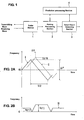
- the obstacle detecting apparatus comprises, as shown in FIG. 1 , a radar device 1 , a pairing processing section 2 that conducts pairing or associating or selecting of an up-beat frequency and a down-beat frequency at specified (predetermined or predeterminable) sampling intervals, a target-object detecting section 3 that detects target objects around the vehicle, obtaining a distance from the vehicle to the target object and a relative speed between the vehicle and the target object based on the up-beat frequency and down-beat frequency that are paired, a prediction processing section 4 that obtains a prediction data for each target object for a next sampling timing.
- the above-described pairing processing section 2, target-object detecting section 3 and prediction processing section 4 can be carried out by an IC chip or computer programs executed by a computer, for example.
- the above-described specified sampling intervals means an interval of a sampling time of the radar device 1 , which preferably is about 100 milliseconds, for example.
- the radar device 1 transmits a frequency modulation-continuous wave (FM-CM) of a millimeter wave and outputs the up-beat frequency and the down-beat frequency.
- FM-CM frequency modulation-continuous wave
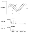
- FIG. 2A shows a graph of a transmitting wave and a receiving wave of the radar device 1 .
- the axis of abscissas of the graph indicates the time, and the axis of ordinates of the graph indicates the frequency.
- the frequency of the transmitting wave oscillates, repeating its going-up and going-down movement, with a center frequency f0 and a half frequency T/2 within an amplitude of frequency modulation ⁇ F, as shown by a solid line I in FIG. 2A.
- the frequency of the receiving wave is also modulated like the transmitting wave.
- the receiving wave may be delayed from the transmitting wave by a delay time ⁇ t that depends on or is related to a distance from the vehicle to a target object that reflects the transmitting wave.
- the frequency of the receiving wave may be shifted from the frequency of the transmitting wave by a Doppler shift ⁇ fd that depends on the relative speed between the vehicle and the target object.
- ⁇ fd Doppler shift
- FIG. 2B shows an up-beat frequency fb(+) and a down-beat frequency fb(-).
- the axis of abscissas of the graph indicates the time, and the axis of ordinates of the graph indicates the frequency.
- the up-beat frequency is a difference between the transmitting frequency and the receiving frequency in a going-up section of the transmitting frequency by the frequency modulation.
- the down-beat frequency is a difference between the transmitting frequency and the receiving frequency in a going-down section of the transmitting frequency by the frequency modulation.
- the down-beat frequency is higher than the up-beat frequency. This corresponds to a case where the target object is approaching.
- the distance R from the vehicle to the target object may be obtained by the up-beat frequency fb(+) and the down-beat frequency fb(-) based on the following equation (1).
- R fb + + fb - ⁇ C / 8 ⁇ T ⁇ ⁇ F
- C indicates the velocity of light.
- T and ⁇ F indicate the frequency of frequency modulation and the amplitude of frequency modulation, respectively, as shown in FIG. 2A .
- the relative speed V between the vehicle and the target object may be obtained by the up-beat frequency fb(+) and the down-beat frequency fb(-) based on the following equation (2).
- V fb - - fb + ⁇ C / 4 ⁇ f ⁇ 0
- f0 indicates the center frequency of frequency modulation as shown in FIG. 2A .
- the radar device 1 When the radar device 1 transmits the millimeter wave substantially forward, the transmitting wave is reflected by various target objects. Not only vehicles that travel in front of the vehicle or travel in the opposite lane toward the vehicle but some guide rails, electric poles and the like may reflect the transmitting wave. Accordingly, the radar device 1 may receive reflected waves from various objects at the same time.
- a graph of FIG. 3A shows the transmitting wave and the receiving waves of a plurality of target objects.
- the axis of abscissas of the graph indicates the time, and the axis of ordinates of the graph indicates the frequency.
- a plurality of reflected waves return as shown by the broken line II with respect to a single transmitting shown by the solid line I in FIG. 3A .
- the reflected waves returning from different objects are shown separately just for convenience. Actually, these may be overlapped, so the plural reflected waves may show irregular and complex shapes.
- respective waves of the up-beat frequency and the down-beat frequency in FIG. 2B may show irregular shapes actually.
- the Fourier transformation preferably is conducted to the waves of these frequencies.
- a graph of FIG. 3B schematically shows results of the Fourier transformation of a beat wave in the going-up section U of the transmitting frequency.
- a graph of FIG. 3C schematically shows results of the Fourier transformation of a beat wave in a going-down section D of the transmitting frequency.
- Each axis of abscissas of these graphs indicates the frequency, and each axis of ordinates of these graphs indicates an intensity.
- three up-beat frequencies f1a, f2a, f3a are outputted.
- three down-beat frequencies f1b, f2b, f3b are outputted.
- the pairing processing section 2 conducts the pairing of the up-beat frequency and the down-beat frequency with priority to a specified (predetermined or predeterminable) target object that has a high certainty of the prediction data obtained by the prediction processing section 4 .
- the pairing processing section 2 of the present embodiment is configured to preferably divide the target objects into a high class in which the target object has a relatively high certainty of the prediction data and a low class in which the target object has a relatively low certainty of the prediction data as a premise of its pairing processing. Specifically, this classification preferably is done based on the number of sampling in which the target object that is actually detected substantially corresponds to the prediction data.
- the target object that has a specified (predetermined or predeterminable) factor or more (preferably three times or more) of its correspondence sampling number is considered as the one in the high certainty class, while the target object that has less than the specified (predetermined or predeterminable) factor (preferably twice or less) of its correspondence sampling number is considered as the one in the low certainty class, for example.
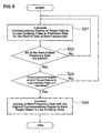
- the pairing processing is conducted to the target objects in the high certainty class (step S1 ) first. Then, the pairing processing is conducted to the target objects in the low certainty class (step S2 ). Finally, the pairing processing is conducted to the new target objects (step S3 ).
- step S11 a degree of the correspondence of the target objects in the high certainty class to the prediction data is calculated for all data of the beat frequencies that are stored in a memory (step S11 ).
- this correspondence degree preferably is calculated by an evaluation function ⁇ shown by the following equation (3).
- This evaluation function ⁇ has parameters of receiving power P, beat frequency F, receiving angle (direction) ⁇ , distance R to the target object, relative speed V of the target object as follows. And, a difference between the data at the present sampling timing (sampling data) and the prediction data is obtained for each parameter, and formalization and weighting are conducted for each parameter.
- n indicates the prediction data based on data at the previous sampling timings or the data at the previous sampling timing
- m indicates the data at the present sampling timing (sampling data).
- PUP indicates the receiving power of the up-beat frequency
- PDW indicates the receiving power of the down-beat frequency
- FUP indicates the up-beat frequency
- FDW indicates the down-beat frequency
- ⁇ indicates the receiving angle (direction)
- R indicates the distance
- V indicates the relative speed.
- A indicates a parameter of a load or weight (dimensionless).
- Ap indicates the weighting of the receiving power
- Af indicates the weighting of the beat frequency
- a ⁇ indicates the weighting of the receiving angle
- Ar indicates the weighting of the distance
- Av indicates the weighting of the speed.
- Pmax, Fmax, ⁇ max, Rmax and Vmax indicate parameters for formalization, respectively. These are values for formalizing the weights of the parameters forming the evaluation function ⁇ , which show the maximum value of the respective parameters.
- the formalization parameters may be included in the load or weight parameters A.
- FIG. 6A shows the sampling data and FIG. 6B shows the prediction data that are to be used as the parameter of the evaluation function ⁇ . These data is stored in the memory not illustrated. Although the memory is not shown in FIG. 1 , there may be provided a memory device that is different from the block shown in FIG. 1 , or this memory may be provided in the block.
- the sampling data is comprised of data on the up-beat side shown at the top of FIG. 6A and data on the down-beat side shown at the bottom of FIG. 6A .
- the up-beat-side data comprises up-beat frequencies f1a - f20a of Nos. 1 - 20.
- the down-beat-side data comprises down-beat frequencies f1b - f20b of Nos. 1 - 20.
- the "receiving power" and the "angle" are stored.
- the prediction data includes the "distance”, “speed”, “angle”, “receiving power”, “up-beat frequency” and “down-beat frequency” for each of the target objects (ID1 - ID20) as shown in FIG. 6B.
- a portion of indication of the value data of the respective parameters is omitted in FIGS. 6A, 6B.
- the distance from the vehicle to the target object and the relative speed between the vehicle and the target object that are obtained by the calculation based on the beat frequencies at the previous sampling timing may be preferably used.
- the values at the previous sampling timing or values that are predicted from these values may be used.
- the values that are obtained by calculation based on the distance and the speed may be used or the up-beat frequency and the down-beat frequency at the previous sampling timing may be stored and used.
- the evaluation function ⁇ is calculated for pairing of all of the up-beat and down-beat frequencies that are obtained from the Fourier transformation (step S12 of FIG. 5 ).
- the frequencies may be paired in order from the one of No. 1, or the pairing of the up-beat and down-beat frequencies that have similar values of the receiving power and the angle may be conducted with priority.
- the correspondence degree of the prediction data and the sampling data for the all target objects in the high certainty class is calculated as described above (step S13 of FIG. 5 ).
- the calculation of the correspondence degree is conducted to these four target objects.
- the pairing (selection) of the up-beat frequency data and the down-beat frequency data in which the correspondence degree is the highest is conducted to each of the four target objects in the high certainty class (ID1 - ID4) (step S14 of FIG. 5 ).
- the pairing of the prediction data of the target object ID2 that provides the highest correspondence degree is the beat frequencies of the up-beat frequency f3a of No. 3 and the down-beat frequency f2b of No. 2.
- the pairing in which the correspondence degree of the prediction data of the target object is the highest is the one that provides the minimum value of the evaluation function ⁇ as described.
- the value of the evaluation function ⁇ is a specified (predetermined or predeterminable) value or greater, it is considered that the pairing of the beat frequencies with respect to its target object has not detected at this sampling timing or iteration.
- the pairing processing is conducted to the target objects in the low certainty class by selecting the rest of the up-beat and down-beat frequencies that are not paired (the step S2 of FIG. 4 ).
- the pairing processing to the target objects in the low certainty class of the step S2 of FIG. 4 will be described referring to a flowchart of FIG. 8 .
- the correspondence degree of the target objects in the high certainty class is calculated for all data of the beat frequencies that are stored in the memory (step S21 of FIG. 8 ).
- the correspondence degree of the target objects in the low certainty class is also calculated by the evaluation function ⁇ of the above-described equation (3).
- the evaluation function ⁇ is calculated for pairing of the rest of the up-beat and down-beat frequencies that are obtained from the Fourier transformation but do not correspond to the target objects in the high certainty class (step S22 of FIG. 8 ).
- FIG. 7 shows an example of the up-beat frequencies and down-beat frequencies of the target objects in the high certainty class, the target objects in the low certainty class, and the new target objects, which are to be paired at pairing processing stages.
- a content of the memory that stores the data of the up-beat frequencies (f1a - f20a) and the down-beat frequencies (f1b - f20b) with respect to the target objects in the high certainty class is schematically shown at the left of FIG. 7 . All of these data are to be paired for the target objects in the high certainty class.
- a content of the memory that stores the data of the up-beat frequencies and the down-beat frequencies with respect to the target objects in the low certainty class is schematically shown at the center of FIG. 7 .
- the data of the up-beat frequencies f1a, f3a, f6a, f10a and the down-beat frequencies f1b, f2b, f4b, f10b that are selected through the pairing for the target objects in the high certainty class are excluded for the data to be paired for the target objects in the low certainty class.
- the correspondence degree of the prediction data and the sampling data for the target objects in the low certainty class is calculated as described above (step S23 of FIG. 8 ). If the four target objects (ID5 - ID8) are the ones in the low certainty class among the twenty target objects (ID1 - ID20) having the prediction data shown in FIG. 6B, the calculation of the correspondence degree is conducted to these four target objects.
- the pairing (selection) of the up-beat and down-beat frequencies in which the correspondence degree is the highest is conducted to each of the four target objects (ID5 - ID8) in the low certainty class (step S24 of FIG. 8 ).
- the pairing in which the correspondence degree of the prediction data of the target object is the highest is the one that provides the minimum value of the evaluation function ⁇ as described.
- the value of the evaluation function ⁇ is a specified (predetermined or predeterminable) value or greater, it is considered that the pairing of the beat frequencies with respect to its target object has not detected at this sampling timing.
- the pairing processing is conducted to the new target objects by selecting the rest of the up-beat and down-beat frequencies that are not paired (the step S3 of FIG. 4 ).
- the pairing of the new target objects preferably is conducted based on the receiving direction (receiving angle) and the intensity (receiving power) of the receiving waves of the up-beat frequency and the down-beat frequency (step S31 of FIG. 9 ). Namely, the pairing of the beat frequencies that have the highest correspondence degree with respect to the receiving angle and the receiving power is conducted (selected), and then indication numbers (ID number) for the new target objects are applied to these.
- the correspondence degree of the receiving angle and the receiving power is calculated for pairing of the rest of the up-beat and down-beat frequencies that are obtained from the Fourier transformation, but do not correspond to the target objects in the high certainty and the low certainty class. (step S32 of FIG. 9 ).
- the calculation of the correspondence degree in this step may be the sum of a weighted difference between the receiving angle of the up-beat frequency and the receiving angle of the down-beat frequency and a weighted difference between the receiving power of the up-beat frequency and the receiving power of the down-beat frequency.
- a content of the memory that stores the data of the up-beat frequencies and the down-beat frequencies with respect to the new target objects is schematically shown at the right of FIG. 7 .
- the data of the up-beat frequencies f1a - f3a, f5a - f7a, f9a, f10a and the down-beat frequencies f1b - f4b, f6b, f7b, f9b, f10b that are selected through the pairing for the target objects in the high certainty class and the target objects in the low certainty class are excluded for the data to be paired for the new target objects.
- step S32 of FIG. 9 the correspondence degree of the receiving angle and the receiving power with respect to the rest of the pairing of the up-beat frequency and the down-beat frequency is calculated.
- step S33 of FIG. 9 the pairing (selection) of the up-beat and down-beat frequencies in which the correspondence degree is the highest is conducted (step S33 of FIG. 9 ).
- the correspondence degree is a specified (predetermined or predeterminable) value or greater, it is considered that the pairing of the beat frequencies with respect to its target object has not detected at this sampling timing.
- the target-object detecting section 3 calculates the distance and the relative speed of the target objects based on the pairing information by the pairing processing section 2 .
- the calculated distance and relative speed become the distance and relative speed of the target object ID2 at the present sampling timing or iteration.
- the prediction processing section 4 calculates the prediction data of the target objects for the next sampling timing based on the information obtained by the pairing processing section 2 and the target-object detecting section 3 .
- a radar device 1 that transmits a frequency modulation-continuous wave (FM-CW) and outputs an up-beat frequency and a down-beat frequency
- a pairing processing section 2 that conducts pairing of the up-beat frequency and the down-beat frequency at specified sampling intervals
- a target-object detecting section 3 that detects target objects around the vehicle, obtaining a distance from the vehicle to the target object and a relative speed between the vehicle and the target object based on the up-beat frequency and down-beat frequency that are paired
- a prediction processing section 4 that obtains a prediction data for each target object for a next sampling timing.
- the pairing processing section 2 conducts the pairing with priority to a specified target object that has a high certainty of the prediction data. Thereby, the pairing of the up-beat and down-beat frequencies can be conducted precisely and quickly.
- the target objects having the prediction data may be divided into three classes instead of the above-described case in which there are provided two classes of the high and low certainty classes.
Landscapes
- Engineering & Computer Science (AREA)
- Radar, Positioning & Navigation (AREA)
- Remote Sensing (AREA)
- Physics & Mathematics (AREA)
- Computer Networks & Wireless Communication (AREA)
- General Physics & Mathematics (AREA)
- Signal Processing (AREA)
- Electromagnetism (AREA)
- Radar Systems Or Details Thereof (AREA)
Applications Claiming Priority (1)
| Application Number | Priority Date | Filing Date | Title |
|---|---|---|---|
| JP2006265231A JP2008082956A (ja) | 2006-09-28 | 2006-09-28 | 車両の障害物検知装置及びその検知方法 |
Publications (1)
| Publication Number | Publication Date |
|---|---|
| EP1906206A1 true EP1906206A1 (de) | 2008-04-02 |
Family
ID=38650165
Family Applications (1)
| Application Number | Title | Priority Date | Filing Date |
|---|---|---|---|
| EP07018383A Withdrawn EP1906206A1 (de) | 2006-09-28 | 2007-09-19 | Vorrichtung und Verfahren zur Hinderniserkennung sowie Computerprogrammprodukt für ein Fahrzeug |
Country Status (3)
| Country | Link |
|---|---|
| US (1) | US20080079629A1 (de) |
| EP (1) | EP1906206A1 (de) |
| JP (1) | JP2008082956A (de) |
Cited By (4)
| Publication number | Priority date | Publication date | Assignee | Title |
|---|---|---|---|---|
| WO2012030615A2 (en) * | 2010-09-01 | 2012-03-08 | Toyota Motor Engineering & Manufacturing North America, Inc. | Multi-range radar system |
| CN103901424A (zh) * | 2012-12-26 | 2014-07-02 | 现代摩比斯株式会社 | 雷达装置及其信号处理方法 |
| CN105891821A (zh) * | 2016-05-24 | 2016-08-24 | 北京环境特性研究所 | 一种机载下视测量目标的自动跟踪方法 |
| CN109407071A (zh) * | 2018-12-13 | 2019-03-01 | 广州极飞科技有限公司 | 雷达测距方法、雷达测距装置、无人机和存储介质 |
Families Citing this family (12)
| Publication number | Priority date | Publication date | Assignee | Title |
|---|---|---|---|---|
| JP5210179B2 (ja) * | 2008-10-30 | 2013-06-12 | 本田技研工業株式会社 | 物体検知装置 |
| JP5557491B2 (ja) * | 2009-08-27 | 2014-07-23 | 富士通テン株式会社 | 信号処理装置、レーダ装置、車両制御システム、信号処理方法、および、プログラム |
| JP5709476B2 (ja) | 2010-11-10 | 2015-04-30 | 富士通テン株式会社 | レーダ装置 |
| JP5982134B2 (ja) * | 2012-02-29 | 2016-08-31 | 富士通テン株式会社 | レーダ装置、および、信号処理方法 |
| US9291708B2 (en) | 2012-03-09 | 2016-03-22 | Raytheon Company | Multiple hypothesis tracking using maximum weight independent set |
| US9441986B2 (en) | 2012-04-17 | 2016-09-13 | Raytheon Company | Locally invariant global hypothesis tracking |
| US8885756B1 (en) * | 2012-10-15 | 2014-11-11 | Maritime Telecommunications Network Inc. | Multi-antenna/multilink diversity management for mobile communication platform |
| JP6280319B2 (ja) * | 2012-10-30 | 2018-02-14 | 株式会社デンソーテン | レーダ装置、および、信号処理方法 |
| JP6200644B2 (ja) | 2012-12-07 | 2017-09-20 | 富士通テン株式会社 | レーダ装置、及び、信号処理方法 |
| JP2014115137A (ja) * | 2012-12-07 | 2014-06-26 | Fujitsu Ten Ltd | レーダ装置、及び、信号処理方法 |
| US10613210B2 (en) * | 2014-12-15 | 2020-04-07 | Mitsubishi Electric Corporation | Radar apparatus |
| KR102046061B1 (ko) * | 2018-04-02 | 2019-11-18 | 재단법인대구경북과학기술원 | 레이더를 이용한 타겟 탐지 장치 및 방법 |
Citations (7)
| Publication number | Priority date | Publication date | Assignee | Title |
|---|---|---|---|---|
| GB2283631A (en) * | 1993-11-06 | 1995-05-10 | Roke Manor Research | Radar |
| US5619208A (en) * | 1995-01-24 | 1997-04-08 | Nippondenso Co., Ltd. | FM-CW radar system |
| EP0932052A2 (de) * | 1998-01-26 | 1999-07-28 | Honda Giken Kogyo Kabushiki Kaisha | Radarvorrichtung |
| EP0981059A2 (de) * | 1998-08-18 | 2000-02-23 | Toyota Jidosha Kabushiki Kaisha | FM-CW Radarvorrichtung |
| EP1319961A1 (de) * | 2001-12-13 | 2003-06-18 | Murata Manufacturing Co., Ltd. | FM-CW-Radarsystem |
| EP1347306A2 (de) * | 2001-11-08 | 2003-09-24 | Fujitsu Ten Limited | Abtastradar |
| JP2004198438A (ja) * | 2004-02-16 | 2004-07-15 | Fujitsu Ten Ltd | 車載レーダ装置 |
Family Cites Families (3)
| Publication number | Priority date | Publication date | Assignee | Title |
|---|---|---|---|---|
| JPH11271429A (ja) * | 1998-03-24 | 1999-10-08 | Toyota Central Res & Dev Lab Inc | Fmcwレーダ装置 |
| JP3703756B2 (ja) * | 2001-11-08 | 2005-10-05 | 富士通テン株式会社 | レーダ装置 |
| JP3801068B2 (ja) * | 2002-02-19 | 2006-07-26 | 株式会社デンソー | Fmcwレーダ装置,プログラム |
-
2006
- 2006-09-28 JP JP2006265231A patent/JP2008082956A/ja active Pending
-
2007
- 2007-08-27 US US11/892,689 patent/US20080079629A1/en not_active Abandoned
- 2007-09-19 EP EP07018383A patent/EP1906206A1/de not_active Withdrawn
Patent Citations (7)
| Publication number | Priority date | Publication date | Assignee | Title |
|---|---|---|---|---|
| GB2283631A (en) * | 1993-11-06 | 1995-05-10 | Roke Manor Research | Radar |
| US5619208A (en) * | 1995-01-24 | 1997-04-08 | Nippondenso Co., Ltd. | FM-CW radar system |
| EP0932052A2 (de) * | 1998-01-26 | 1999-07-28 | Honda Giken Kogyo Kabushiki Kaisha | Radarvorrichtung |
| EP0981059A2 (de) * | 1998-08-18 | 2000-02-23 | Toyota Jidosha Kabushiki Kaisha | FM-CW Radarvorrichtung |
| EP1347306A2 (de) * | 2001-11-08 | 2003-09-24 | Fujitsu Ten Limited | Abtastradar |
| EP1319961A1 (de) * | 2001-12-13 | 2003-06-18 | Murata Manufacturing Co., Ltd. | FM-CW-Radarsystem |
| JP2004198438A (ja) * | 2004-02-16 | 2004-07-15 | Fujitsu Ten Ltd | 車載レーダ装置 |
Cited By (10)
| Publication number | Priority date | Publication date | Assignee | Title |
|---|---|---|---|---|
| WO2012030615A2 (en) * | 2010-09-01 | 2012-03-08 | Toyota Motor Engineering & Manufacturing North America, Inc. | Multi-range radar system |
| WO2012030615A3 (en) * | 2010-09-01 | 2012-05-31 | Toyota Motor Engineering & Manufacturing North America, Inc. | Multi-range radar system |
| US8405541B2 (en) | 2010-09-01 | 2013-03-26 | Toyota Motor Engineering & Manufacturing North America, Inc. | Multi-range radar system |
| CN103901424A (zh) * | 2012-12-26 | 2014-07-02 | 现代摩比斯株式会社 | 雷达装置及其信号处理方法 |
| KR20140083709A (ko) * | 2012-12-26 | 2014-07-04 | 현대모비스 주식회사 | 레이더 장치 및 이에 적용되는 신호처리방법 |
| CN103901424B (zh) * | 2012-12-26 | 2017-04-12 | 现代摩比斯株式会社 | 雷达装置及其信号处理方法 |
| CN105891821A (zh) * | 2016-05-24 | 2016-08-24 | 北京环境特性研究所 | 一种机载下视测量目标的自动跟踪方法 |
| CN105891821B (zh) * | 2016-05-24 | 2018-04-17 | 北京环境特性研究所 | 一种机载下视测量目标的自动跟踪方法 |
| CN109407071A (zh) * | 2018-12-13 | 2019-03-01 | 广州极飞科技有限公司 | 雷达测距方法、雷达测距装置、无人机和存储介质 |
| CN109407071B (zh) * | 2018-12-13 | 2021-07-20 | 广州极飞科技股份有限公司 | 雷达测距方法、雷达测距装置、无人机和存储介质 |
Also Published As
| Publication number | Publication date |
|---|---|
| JP2008082956A (ja) | 2008-04-10 |
| US20080079629A1 (en) | 2008-04-03 |
Similar Documents
| Publication | Publication Date | Title |
|---|---|---|
| EP1906206A1 (de) | Vorrichtung und Verfahren zur Hinderniserkennung sowie Computerprogrammprodukt für ein Fahrzeug | |
| EP1371997B1 (de) | Verfahren zum erkennen eines stationären objekts auf der strasse durch radar | |
| US9971022B2 (en) | Radar apparatus | |
| US9110164B2 (en) | Radar apparatus and signal processing method | |
| US6888494B2 (en) | FMCW radar system | |
| US9709674B2 (en) | Radar device and signal processing method | |
| JP3788452B2 (ja) | Fmcwレーダ装置 | |
| US6661370B2 (en) | Radar data processing apparatus and data processing method | |
| US20100271257A1 (en) | Radar apparatus | |
| US9709665B2 (en) | Radar apparatus and signal processing method | |
| WO2011070426A2 (en) | Obstacle detection device | |
| US9977126B2 (en) | Radar apparatus | |
| US10473760B2 (en) | Radar device and vertical axis-misalignment detecting method | |
| KR20170058663A (ko) | 차량용 레이더 장치 및 그의 타겟 결정 방법 | |
| US9383440B2 (en) | Radar apparatus and signal processing method | |
| JP2015155807A (ja) | レーダ装置、車両制御システム、および、信号処理方法 | |
| JP2010096589A (ja) | 信号処理装置、レーダ装置、及び信号処理方法 | |
| JP2009092410A (ja) | レーダ装置、及び物標検出方法 | |
| US9442183B2 (en) | Radar apparatus and signal processing method | |
| US9689975B2 (en) | Radar apparatus | |
| US10698105B2 (en) | Radar device and peak processing method | |
| JP2981885B1 (ja) | 道路状況把握装置 | |
| JP2008026239A (ja) | レーダ | |
| US10520585B2 (en) | Radar device and signal processing method | |
| US20210286048A1 (en) | Radar device |
Legal Events
| Date | Code | Title | Description |
|---|---|---|---|
| PUAI | Public reference made under article 153(3) epc to a published international application that has entered the european phase |
Free format text: ORIGINAL CODE: 0009012 |
|
| AK | Designated contracting states |
Kind code of ref document: A1 Designated state(s): AT BE BG CH CY CZ DE DK EE ES FI FR GB GR HU IE IS IT LI LT LU LV MC MT NL PL PT RO SE SI SK TR |
|
| AX | Request for extension of the european patent |
Extension state: AL BA HR MK YU |
|
| 17P | Request for examination filed |
Effective date: 20080925 |
|
| 17Q | First examination report despatched |
Effective date: 20081023 |
|
| AKX | Designation fees paid |
Designated state(s): DE |
|
| STAA | Information on the status of an ep patent application or granted ep patent |
Free format text: STATUS: THE APPLICATION IS DEEMED TO BE WITHDRAWN |
|
| 18D | Application deemed to be withdrawn |
Effective date: 20090303 |