EP1906162A1 - Elektronisches klinisches thermometer und steuerverfahren und steuerprogramm für ein elektronisches klinisches thermometer - Google Patents
Elektronisches klinisches thermometer und steuerverfahren und steuerprogramm für ein elektronisches klinisches thermometer Download PDFInfo
- Publication number
- EP1906162A1 EP1906162A1 EP06767893A EP06767893A EP1906162A1 EP 1906162 A1 EP1906162 A1 EP 1906162A1 EP 06767893 A EP06767893 A EP 06767893A EP 06767893 A EP06767893 A EP 06767893A EP 1906162 A1 EP1906162 A1 EP 1906162A1
- Authority
- EP
- European Patent Office
- Prior art keywords
- prediction
- clinical thermometer
- temperature
- electronic clinical
- value
- Prior art date
- Legal status (The legal status is an assumption and is not a legal conclusion. Google has not performed a legal analysis and makes no representation as to the accuracy of the status listed.)
- Granted
Links
Images




Classifications
-
- G—PHYSICS
- G01—MEASURING; TESTING
- G01K—MEASURING TEMPERATURE; MEASURING QUANTITY OF HEAT; THERMALLY-SENSITIVE ELEMENTS NOT OTHERWISE PROVIDED FOR
- G01K7/00—Measuring temperature based on the use of electric or magnetic elements directly sensitive to heat ; Power supply therefor, e.g. using thermoelectric elements
- G01K7/42—Circuits effecting compensation of thermal inertia; Circuits for predicting the stationary value of a temperature
-
- G—PHYSICS
- G01—MEASURING; TESTING
- G01K—MEASURING TEMPERATURE; MEASURING QUANTITY OF HEAT; THERMALLY-SENSITIVE ELEMENTS NOT OTHERWISE PROVIDED FOR
- G01K13/00—Thermometers specially adapted for specific purposes
- G01K13/20—Clinical contact thermometers for use with humans or animals
Definitions
- the present invention relates to a high-speed body temperature calculation technique in an electronic clinical thermometer.
- prediction operation starts at a time when the actual measurement value is equal to or more than a predetermined value and the rate of temperature rise is equal to or more than a predetermined value.
- a prediction settling point is given at a time when a variation in prediction value falls within a predetermined value.
- the parameters a 1 , b 1 , a 2 , b 2 , c 2 , and d 2 are constants selected to keep the precision of the additional amount U constant regardless of patients and temperature detection elements.
- Parameters used for prediction calculation equations are grouped depending on the features of patients and the characteristics of temperature detection elements.
- a technique for determining parameter groups based on actual measurement values of the temperature detection element to allow prediction with a higher precision there is also disclosed a technique for changing corresponding parameter groups based on temporal changes in prediction values upon determining the parameter groups to allow prediction with a higher precision (patent reference 1).
- thermometer Upon power-on of an electronic clinical thermometer, data necessary for temperature measurement such as temperature measurement parameters are read out from a nonvolatile memory such as an EEPROM. A conventional arrangement reads out these data immediately after power-on.
- thermometer Upon power-on of the electronic clinical thermometer, when the thermometer is to be inserted into an underarm of a user and the metal cap at its distal end comes into contact with an electrostatically charged piece of clothing worn by the user, the thermometer may fail to read out the data necessary for temperature measurement due to an electrostatic influence.
- the conventional clinical thermometer fails to read out data from the EEPROM, it informs the user of a temperature measurement error and prompts him to retry the temperature measurement (patent reference 2).
- Patent Reference 1 Japanese Patent No. 3100741
- Patent Reference 2 Japanese Patent Laid-Open No. 59-114424
- the present invention has been made in consideration of the above problem, and has as its object to implement an electronic clinical thermometer capable of measurement with a higher precision within a shorter period of time and to reduce the load on a measurement operator.
- an electronic clinical thermometer for predicting an equilibrium temperature based on a temporal change in actual measurement value of a measurement target temperature detected by a temperature detection element, comprising prediction value derivation means for deriving a plurality of prediction values from actual measurement values in accordance with a plurality of prediction equations, selection means for selecting one of the plurality of prediction equations based on the selected prediction equation, and display output means for displaying a prediction value result based on the selected prediction equation.
- the electronic clinical thermometer is characterized in that the selection means selects a prediction equation by which a temporal change in prediction value is minimum.
- an electronic clinical thermometer for predicting an equilibrium temperature based on a temporal change in the actual measurement value of a measurement target temperature detected by a temperature detection element, comprising prediction value derivation means for deriving a plurality of prediction values from actual measurement values in accordance with a plurality of prediction equations, selection means for selecting one of the plurality of prediction equations based on a temporal change in actual measurement value, and display output means for displaying a prediction value result derived based on the selected prediction equation.
- the electronic clinical thermometer is characterized in that the plurality of prediction equations are set in correspondence with a plurality of groups obtained depending on a characteristic of the temporal change in the actual measurement value.
- the electronic clinical thermometer is characterized in that the heat capacity of the temperature measurement element and its vicinity is low but the heat response is high.
- the electronic clinical thermometer is further characterized by comprising a temperature measurement start means for detecting a temperature rise and starting temperature measurement operation, storage means for storing data necessary for temperature measurement, including at least a temperature measurement end condition, and readout timing control means for controlling a readout timing for reading out the data from the storage means, wherein the readout timing means reads out the necessary data from the storage means when the predetermined condition is met upon power-on of the electronic clinical thermometer.
- the electronic clinical thermometer is characterized in that the predetermined condition is detection of a temperature rise exceeding a predetermined period of time upon power-on of the electronic clinical thermometer.
- the electronic clinical thermometer is characterized in that the temperature measurement end condition is defined such that the temperature rise within the predetermined period of time is less than a predetermined temperature value.
- the electronic clinical thermometer is characterized in that the storage means comprises a nonvolatile memory.
- the electronic clinical thermometer is characterized in that the nonvolatile memory comprises an EEPROM.
- a method of controlling an electronic clinical thermometer has the following steps. That is, there is provided a method of controlling an electronic clinical thermometer for predicting an equilibrium temperature based on a temporal change in actual measurement value of a measurement target temperature detected by a temperature detection element, comprising a prediction value derivation step of deriving a plurality of prediction values from actual measurement values in accordance with a plurality of prediction equations, a selection step of selecting one of the plurality of prediction equations based on the selected prediction equation, and a display output step of displaying a prediction value result based on the selected prediction equation.
- a control program of an electronic clinical thermometer has the following program codes. That is, there is provided a control program of an electronic clinical thermometer for predicting an equilibrium temperature based on a temporal change in actual measurement value of a measurement target temperature detected by a temperature detection element, comprising a program code for implementing a prediction value derivation step of deriving a plurality of prediction values from actual measurement values in accordance with a plurality of prediction equations, a program code for implementing a selection step of selecting one of the plurality of prediction equations based on the selected prediction equation, and a program code for implementing a display output step of displaying a prediction value result based on the selected prediction equation.
- an electronic clinical thermometer capable of measurement with a higher precision within a shorter period of time, thereby reducing the load on a measurement operator.
- the heat capacity of a temperature sensor of an electronic clinical thermometer is reduced to increase the heat response, thereby shortening the measurement time for obtaining actual measurement values used for prediction.
- selection is made based on the calculation results using a plurality of prediction equations. This makes it possible to suppress a decrease in precision caused by variations in actual measurement values along with an increase in heat response.
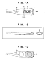
- Figs. 1A to 1C are views showing the outer appearance of an electronic clinical thermometer according to an embodiment, in which Fig. 1A is a front view, Fig. 1B is a side view, and Fig. 1C is a rear view.
- a main body case 2 houses an electronic circuit such as an arithmetic control unit 20, a buzzer 31, a battery (power supply unit) 40, and the like.
- a metal cap 3 made of stainless steel houses a temperature measurement unit including a thermistor 13 (see Fig. 2 ) necessary for body temperature measurement. The temperature measurement unit is fixed in the metal cap 3 with an adhesive. An adhesive liquid-tightly bonds and fixes the main body cap 2 and the metal cap 3.
- the metal cap 3 transfers the body temperature (temperature) and protects the thermistor 13 against an external impact or the like.
- the main body case 2 has an outer diameter of about 3 mm, a thickness of about 0.2 mm, an overall length of about 8 mm, and a weight of 240 to 250 ⁇ m.
- the length of a joint portion at the distal end of the main body case 2 is about 3.5 mm to 5 mm.
- the heat capacity of the heat sensitive portion including the metal cap 3 incorporating the thermistor 13 is as low as about 0.1 J/°C.
- the main body case 2 is made of a styrene-based resin (high impact styrole or ABS resin) or polyolefin-based resin (polypropylene or polyethylene) containing about 1 to 2.5 wt% of a silver zirconium phosphate compound.
- a transparent window portion 2d which covers a display unit 30 and the remaining portion of the main body case 3 are molded in two colors.
- the window portion 2d is made of a transparent resin such as a styrene-based resin (e.g., polystyrene or a butadiene-styrene copolymer), a polyolefin-based resin (e.g., poly-2-methyl pentene or polypropylene); an acrylic resin (e.g., polymethylmethacrylate), a cellulose ester (e.g., cellulose acetate), or a polyester (e.g., polyethylene terephthalate).
- a styrene-based resin e.g., polystyrene or a butadiene-styrene copolymer
- a polyolefin-based resin e.g., poly-2-methyl pentene or polypropylene
- an acrylic resin e.g., polymethylmethacrylate
- a cellulose ester e.g., cellulose acetate
- polyester e.g., poly
- a battery lid 2d is used to replace a battery.
- a broken line indicates a storage position of the battery (power supply unit) 40. When the battery 40 is stored, the center of gravity is located on the front side in the longitudinal direction of the thermometer.
- a prediction mode display portion 30a displays a prediction mode.
- a mute (silent) mode display portion 30b displays a so-called mute (silent) mode in which a buzzer sound is not generated.
- the electronic clinical thermometer has a width of about 28 mm, a thickness of about 10 mm, and a weight of about 20 gw.
- the position of the center of gravity, width, weight, and means for preventing from sliding stabilize the electronic clinical thermometer when it is attached to part of the human body.
- Fig. 2 is an internal block diagram showing the arrangement of the electronic clinical thermometer of this embodiment.
- This electronic clinical thermometer comprises a temperature measurement unit 10 for measuring a temperature and outputting it as a digital value, an arithmetic control unit 20 for calculating a prediction temperature from a measured temperature and controlling this electronic clinical thermometer, and a display unit 30 which displays a measurement result and comprises a backlight LED 30c.
- the temperature measurement unit 10 comprises the thermistor 13, a capacitor 14, and a temperature measurement CR oscillator 11.
- the thermistor 13 and capacitor 14 are connected in parallel with each other and arranged in the temperature sensitive portion.
- the temperature measurement unit 10 outputs the temperature as a digital amount in accordance with the count value of a counter 16 which corresponds to the temperature of the thermistor 13. Note that the arrangement of the electronic clinical thermometer 10 is merely an example and is not limited to this.
- the arithmetic control unit 20 comprises an EEPROM 22a which stores parameters necessary for body temperature measurement, a RAM 23 for storing time-series measured temperatures, a ROM 22 which stores programs such as prediction equations, a display control unit 30d for controlling the display unit 30, the counter 16 for counting oscillation signals from the temperature measurement CR oscillator 11, an arithmetic processing unit 21 for performing processing under conditions written in the EEPROM 22a in accordance with the programs in the ROM 22, and a control circuit 50 for controlling the counter 16, arithmetic processing unit 21, and display control unit 30d.
- EEPROM 22a which stores parameters necessary for body temperature measurement
- RAM 23 for storing time-series measured temperatures
- ROM 22 which stores programs such as prediction equations
- a display control unit 30d for controlling the display unit 30, the counter 16 for counting oscillation signals from the temperature measurement CR oscillator 11, an arithmetic processing unit 21 for performing processing under conditions written in the EEPROM 22a in accordance with the programs in the ROM 22, and a control
- the heat capacity of the thermistor 13 and its vicinity is much smaller than that of the conventional prediction type electronic clinical thermometer and is thus excellent in heat response.
- the heat capacity of the peripheral portion includes those of the metal cap 3 contacting a measurement target of the body and covering the thermistor 13, and the adhesive between the metal cap 3 and the thermistor 13.
- Fig. 3 is a flowchart for explaining operation for controlling a readout timing of data necessary for temperature measurement.
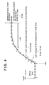
- Fig. 4 is a view showing the correspondence between a temperature rise curve example and the operations in Fig. 3 . Note that the arithmetic processing unit (CPU) 21 performs operation control of the steps in Fig. 3 .
- CPU arithmetic processing unit
- the CPU When the CPU detects power-on in step S101 in Fig. 3 , the CPU reads out the program corresponding to the flowchart in Fig. 3 from the ROM 24 and expands the program in the RAM 23 to prepare for the start of operation. As shown in Fig. 4 , the CPU samples temperature data every predetermined period of time interval, for example, 500 msec.
- the temperature rise detection counter 25 counts the number of times the temperature gradient is equal to or more than 0.03°C/500 msec.
- the CPU executes arithmetic operation for obtaining a temperature gradient at each point from the temperature data obtained upon sampling.
- step S104 determines in step S104 whether the temperature gradient calculated in step S103 is equal to or more than a predetermined value (e.g., 0.03 °C/500 msec). If YES in step S104, the process advances to step S105; otherwise, the process returns to step S102 to reset the counter value Ct.
- a predetermined value e.g. 0.03 °C/500 msec.
- the CPU counts up the counter value Ct in step S105.
- the CPU determines in step S106 whether the counter value is a predetermined value (e.g., 3). If YES in step S106, the process advances to step S107; otherwise, the process returns to step S103 to execute temperature gradient calculation or the like (steps S103 to S105).
- the CPU detects that the temperature rise is sufficient.
- the CPU determines that the thermometer has been inserted in the measurement target (e.g., an underarm or in a mouth). Since the thermometer has already been inserted, data read error does not occur due to an electrostatic influence. That is, even if static electricity is generated during insertion, it is conducted to the human body having an impedance lower than that of the metal cap 3 along the surface layer of the main body case 2 made of a resin. The internal circuit of the thermometer is free from the electrostatic influence.
- step S107 data necessary for temperature measurement is read out from the EEPROM 22a and stored in the RAM 23.
- step S108 the CPU executes temperature measurement operation using the data read out from the EEPROM 22a.
- the CPU determines in step S109 whether the temperature rise is less than 0.1°C per predetermined value (e.g., 4 sec). If NO in step S108, the temperature measurement operation continues in step S108. If YES in step S108, the CPU determines that the temperature measurement is complete. The buzzer generates a temperature measurement end sound to inform the user of the end of temperature measurement.
- 0.1°C per predetermined value e.g. 4 sec
- the temperature curve between points A and B is flat. This indicates that the thermometer is not inserted in the measurement target yet.
- the CPU detects a continuous temperature rise of 0.03°C/500 msec three times at points C, D, and E. The CPU determines that the thermometer was inserted into the measurement target at the point B. That is, the internal temperature measurement start time is the point B.
- the CPU determines that the temperature rise is equal to or more than the predetermined value (e.g., 0.03°C) consecutively a predetermined number of times (three times), the CPU determines that the thermometer has been inserted into the measurement target. At this timing, the CPU reads out the data necessary for temperature measurement from the EEPROM 22a, thereby starting the temperature measurement.
- the predetermined value e.g. 0.03°C
- the temperature rise is monitored even during temperature measurement operation. If the temperature rise is less than a predetermined value (e.g., 0.1°C) per predetermined value (e.g., 4 sec), the temperature measurement ends. In the temperature curve in Fig. 4 , the CPU determines that the temperature rise between points F and G is less than 0.1°C, and determines the end of temperature measurement.
- a predetermined value e.g., 0.1°C
- predetermined value e.g. 4 sec
- Fig. 5 is a graph exemplifying changes in actual measurement values of the electronic clinical thermometer inserted in an underarm.
- the actual measurement value approaches the equilibrium temperature along with elapse of time.
- the temperature rise rate changes depending on the measurement conditions such as physical constitutions of patients, and contact states between the temperature and the body surface.
- the CPU groups the actual measurement values in accordance with their temporal change characteristics.
- the heat response characteristic of the temperature detection element is good, and the temporal change characteristics of the actual measurement values tend to vary.
- the actual measurement values are grouped into the number of groups (in this case, 13 groups) larger than that of the number of conventional groups (e.g., 7 groups).
- Fig. 6 is a graph showing a grouping example in accordance with the temporal change characteristics of actual measurement values.
- the points in the graph indicate the distribution of measurement samples.
- the first group includes actual measurement values having a highest heat response and high initial temperatures, but the temperature rise immediately declines.
- the eighth group includes actual measurement values having a lowest heat response and low initial temperatures, but the temperature rise lasts longer. Since the actual measurement values belonging to the ninth and tenth groups fall greatly outside the normal actual measurement value changes, these values may be regarded as prediction disable values, and the measurement may end with an error. Alternatively, the actual measurement value may be displayed without any prediction.
- the actual measurement values belonging to the 11th and 12th groups indicate body temperatures of 36.5°C or more.
- Fig. 7 is a flowchart of a body temperature measurement processing sequence in the electronic clinical thermometer of the first embodiment. The following operation starts upon power-on or the like as a trigger by pressing the power ON/OFF switch 4.
- the arithmetic processing unit 21 performs the program stored in the ROM 22 to implement the respective steps to be described below.
- the CPU initializes the electronic clinical thermometer in step S501 and starts detecting the temperature value of the thermistor 13. For example, the CPU detects temperature values every 0.5 sec using the sensor.
- the CPU starts storing the above timing and temperature value as the specific timing and actual measurement value data (time-series data) in the RAM 23. That is, upon detecting an abrupt rise in temperature, the CPU determines that the measurement operator inserted the thermometer in a predetermined measurement target.
- step S503 determines in step S503 whether a. decrease in measurement temperature is observed during measurement. If YES in step S503, the process advances to step S511; otherwise, the process advances to step S504.
- step S504 the CPU sequentially derives prediction values (every 0.5 sec) by the above-described prediction equation using the data stored in step S502.
- prediction calculations are simultaneously performed using the prediction equations respectively corresponding to the plurality of groups shown in Fig. 4 .
- the calculations (10 different calculations of 1 to 8, 11, and 12) may be performed for all the groups, or the calculations may be performed for some peripheral groups of a given group set based on several actual measurement values as elements.
- a predetermined period of time e.g. 25 sec
- step S506 the CPU stops calculating values except the groups determined in step S505 and continuously performs prediction calculations for the determined groups for a predetermined period of time.
- the predetermined range e.g., 0.1°C
- step S508 the buzzer 31 is operated to generate a buzzer sound indicating the prediction settlement, and the process advances to step S509.
- step S509 the display unit 30 displays the derived prediction value.
- the CPU determines in step S510 whether an instruction to indicate the end of display of the temperature measurement result is accepted. For example, the CPU may determine whether the power ON/OFF switch 4 is pressed, or the display may automatically end a predetermined period of time after the prediction temperature display.
- step S511 the CPU corrects the measured data. If the CPU normally corrects the data, the process returns to step S502; otherwise, the process advances to step S512.
- step S512 the buzzer 31 is operated to generate a buzzer sound indicating an error, thereby ending the temperature measurement.
- the buzzer sound is desirably different from that in step S508.
- step S513 when a predetermined period of time (e.g., 45 sec) has elapsed from the start of measurement by using, for example, a timer, the CPU forcibly finishes the prediction, and the process advances to step S507. That is, the CPU determines the prediction value obtained at that time as the final prediction value.
- a predetermined period of time e.g. 45 sec
- the temperature measurement operation is completed through the above steps.
- step S505 Processing (corresponding to step S505) for determining a group corresponding to a prediction equation used for the final prediction value by using a plurality of prediction values derived based on a plurality of prediction equations will be described.
- Fig. 8 is a graph exemplifying actual measurement values and temporal changes in prediction values based on the plurality of prediction equations.
- Fig. 8 shows the actual measurement values detected by the thermistor 13 and the changes in prediction values corresponding to five groups, that is, the first group to the fifth group derived in step S504.
- the groups are determined based on the temporal changes in these prediction values. That is, the correspondence between a prediction value having a highest precision and the prediction equation of a specific group will be determined.
- a group corresponding to a time series whose prediction values have small variations is finally selected as an optimal group in this measurement.
- the prediction calculations are performed for a plurality of groups, and the temporal changes of the prediction values are compared to determine a group, thereby achieving higher-precision prediction.
- prediction values are derived a predetermined period of time after group determination (steps S506 and S507), and the final prediction value is determined.
- a change e.g., 0.05°C
- the prediction value corresponding to the determined group is regarded to be sufficiently high. This prediction value may be determined as the final prediction value.
- a group can be determined based on temporal changes in actual measurement values. That is, the time-series data of the actual measurement values may be made to correspond to the grouping table shown in Fig. 6 , and a group having a largest number of corresponding points may be selected and determined.
- the electronic clinical thermometer of this embodiment can be implemented as an electronic clinical thermometer capable of high-precision measurement within a short time, thereby reducing the load on the measurement operator.
- the object of the present invention is realized even by supplying a program for implementing the functions of the embodiment described above to a system or an apparatus, and causing the computer of the system or the apparatus to read out and execute the supplied program codes. Therefore, in order to cause the computer to implement the functions of the present invention, the program codes themselves installed in the computer constitutes the technical scope of the present invention.
- the functions of the above-described embodiment are also realized when the program codes read out from the storage medium are written in the memory of a function expansion board inserted into the computer or a function expansion unit connected to the computer, and the CPU of the function expansion board or function expansion unit performs part or all of actual processing the instructions of the program codes. This processing also implement the functions of the above-described embodiment.
Landscapes
- Physics & Mathematics (AREA)
- General Physics & Mathematics (AREA)
- Measuring Temperature Or Quantity Of Heat (AREA)
Applications Claiming Priority (2)
| Application Number | Priority Date | Filing Date | Title |
|---|---|---|---|
| JP2005203127A JP4949648B2 (ja) | 2005-07-12 | 2005-07-12 | 電子体温計およびその制御方法 |
| PCT/JP2006/313387 WO2007007605A1 (ja) | 2005-07-12 | 2006-07-05 | 電子体温計、電子体温計の制御方法並びに制御プログラム |
Publications (3)
| Publication Number | Publication Date |
|---|---|
| EP1906162A1 true EP1906162A1 (de) | 2008-04-02 |
| EP1906162A4 EP1906162A4 (de) | 2009-05-06 |
| EP1906162B1 EP1906162B1 (de) | 2012-04-18 |
Family
ID=37636999
Family Applications (1)
| Application Number | Title | Priority Date | Filing Date |
|---|---|---|---|
| EP06767893A Not-in-force EP1906162B1 (de) | 2005-07-12 | 2006-07-05 | Elektronisches klinisches thermometer, steuerverfahren und steuerprogramm für ein elektronisches klinisches thermometer |
Country Status (4)
| Country | Link |
|---|---|
| EP (1) | EP1906162B1 (de) |
| JP (1) | JP4949648B2 (de) |
| CN (1) | CN101233397B (de) |
| WO (1) | WO2007007605A1 (de) |
Cited By (2)
| Publication number | Priority date | Publication date | Assignee | Title |
|---|---|---|---|---|
| DE102010019113A1 (de) * | 2010-04-30 | 2011-11-03 | Wilo Se | Verfahren zur näherungsweisen Berechnung der operativen Temperatur eines Raumes |
| EP2868267A4 (de) * | 2013-07-01 | 2015-10-28 | Willile Mobile Inc | Körpertemperaturmessvorrichtung, körpertemperaturmesssystem und körpertemperaturmessverfahren |
Families Citing this family (8)
| Publication number | Priority date | Publication date | Assignee | Title |
|---|---|---|---|---|
| JP4824372B2 (ja) * | 2005-09-08 | 2011-11-30 | テルモ株式会社 | 婦人用電子体温計、婦人用電子体温計の制御方法並びに制御プログラム |
| JP4819449B2 (ja) * | 2005-09-08 | 2011-11-24 | テルモ株式会社 | 婦人用電子体温計、婦人用電子体温計の制御方法並びに制御プログラム |
| JP5596323B2 (ja) * | 2009-09-28 | 2014-09-24 | テルモ株式会社 | 電子体温計及び電子体温計の制御方法 |
| JP2013061289A (ja) * | 2011-09-14 | 2013-04-04 | Terumo Corp | 医療用装置及び制御方法 |
| JP5952438B1 (ja) | 2015-01-22 | 2016-07-13 | ファナック株式会社 | 電動機の温度推定装置 |
| JP7189089B2 (ja) * | 2019-06-07 | 2022-12-13 | Jfeアドバンテック株式会社 | 温度予測方法、温度予測装置、及び温度予測用プログラム |
| JP2022177341A (ja) * | 2019-10-31 | 2022-12-01 | 株式会社トライアンドイー | 温度センサの補正方法 |
| CN113720489A (zh) * | 2021-09-30 | 2021-11-30 | 湖南心诺智造医疗器械有限公司 | 电子体温计和温度测量方法 |
Family Cites Families (6)
| Publication number | Priority date | Publication date | Assignee | Title |
|---|---|---|---|---|
| US4592000A (en) * | 1982-06-24 | 1986-05-27 | Terumo Corporation | Electronic clinical thermometer, and method of measuring body temperature |
| JPS5918425A (ja) * | 1982-07-23 | 1984-01-30 | Hitachi Ltd | 電子体温計 |
| JPS59114424A (ja) | 1982-12-21 | 1984-07-02 | Terumo Corp | 電子体温計 |
| JPH07111383B2 (ja) * | 1989-10-05 | 1995-11-29 | テルモ株式会社 | 平衡温度の検出方法及び電子体温計 |
| US5392031A (en) * | 1992-03-17 | 1995-02-21 | Terumo Kabushiki Kaisha | Electronic clinical thermometer |
| JP3100741B2 (ja) * | 1992-03-17 | 2000-10-23 | テルモ株式会社 | 電子体温計 |
-
2005
- 2005-07-12 JP JP2005203127A patent/JP4949648B2/ja not_active Expired - Lifetime
-
2006
- 2006-07-05 WO PCT/JP2006/313387 patent/WO2007007605A1/ja not_active Ceased
- 2006-07-05 EP EP06767893A patent/EP1906162B1/de not_active Not-in-force
- 2006-07-05 CN CN2006800250091A patent/CN101233397B/zh active Active
Cited By (3)
| Publication number | Priority date | Publication date | Assignee | Title |
|---|---|---|---|---|
| DE102010019113A1 (de) * | 2010-04-30 | 2011-11-03 | Wilo Se | Verfahren zur näherungsweisen Berechnung der operativen Temperatur eines Raumes |
| EP2383556A3 (de) * | 2010-04-30 | 2014-06-11 | Wilo Se | Verfahren zur näherungsweisen Berechnung der operativen Temperatur eines Raumes |
| EP2868267A4 (de) * | 2013-07-01 | 2015-10-28 | Willile Mobile Inc | Körpertemperaturmessvorrichtung, körpertemperaturmesssystem und körpertemperaturmessverfahren |
Also Published As
| Publication number | Publication date |
|---|---|
| CN101233397B (zh) | 2011-07-20 |
| EP1906162B1 (de) | 2012-04-18 |
| JP2007024530A (ja) | 2007-02-01 |
| WO2007007605A1 (ja) | 2007-01-18 |
| JP4949648B2 (ja) | 2012-06-13 |
| EP1906162A4 (de) | 2009-05-06 |
| CN101233397A (zh) | 2008-07-30 |
Similar Documents
| Publication | Publication Date | Title |
|---|---|---|
| US8025438B2 (en) | Electronic clinical thermometer, method of controlling the same, and control program | |
| US7778791B2 (en) | Electronic clinical thermometer, method of controlling the same, and control program | |
| EP0122622B1 (de) | Elektronisches Thermometer | |
| CA1239477A (en) | Electronic thermometer with fixed response time | |
| US20110098966A1 (en) | Electronic clinical thermometer and operation control method | |
| EP1906162B1 (de) | Elektronisches klinisches thermometer, steuerverfahren und steuerprogramm für ein elektronisches klinisches thermometer | |
| JP2011075580A (ja) | 予測型体温測定システム | |
| JPS62265540A (ja) | 電子体温計 | |
| CA1244944A (en) | Clinical thermometer | |
| JP4824372B2 (ja) | 婦人用電子体温計、婦人用電子体温計の制御方法並びに制御プログラム | |
| JP2015111049A (ja) | 電子体温計及びその制御方法 | |
| CN102725617A (zh) | 电子体温计以及控制方法 | |
| JP5432066B2 (ja) | 電子体温計及びその制御方法 | |
| JP4754893B2 (ja) | 電子体温計 | |
| JP4738921B2 (ja) | 電子体温計およびその制御方法 | |
| JPS612029A (ja) | 電子体温計 | |
| JP4920922B2 (ja) | 電子体温計 | |
| JPS6036926A (ja) | 電子体温計 | |
| JPH0351725Y2 (de) | ||
| JPH0755583A (ja) | 電子体温計 | |
| JPS59190630A (ja) | 電子体温計 | |
| JPS61189425A (ja) | 電子体温計 | |
| JPS62190427A (ja) | 電子体温計 | |
| WO2013136586A1 (ja) | 電子体温計 |
Legal Events
| Date | Code | Title | Description |
|---|---|---|---|
| PUAI | Public reference made under article 153(3) epc to a published international application that has entered the european phase |
Free format text: ORIGINAL CODE: 0009012 |
|
| 17P | Request for examination filed |
Effective date: 20080201 |
|
| AK | Designated contracting states |
Kind code of ref document: A1 Designated state(s): AT BE BG CH CY CZ DE DK EE ES FI FR GB GR HU IE IS IT LI LT LU LV MC NL PL PT RO SE SI SK TR |
|
| DAX | Request for extension of the european patent (deleted) | ||
| A4 | Supplementary search report drawn up and despatched |
Effective date: 20090406 |
|
| 17Q | First examination report despatched |
Effective date: 20090922 |
|
| REG | Reference to a national code |
Ref country code: DE Ref legal event code: R079 Ref document number: 602006028950 Country of ref document: DE Free format text: PREVIOUS MAIN CLASS: G01K0007420000 Ipc: G01K0013000000 |
|
| GRAP | Despatch of communication of intention to grant a patent |
Free format text: ORIGINAL CODE: EPIDOSNIGR1 |
|
| RIC1 | Information provided on ipc code assigned before grant |
Ipc: G01K 7/42 20060101ALI20110930BHEP Ipc: G01K 13/00 20060101AFI20110930BHEP |
|
| RTI1 | Title (correction) |
Free format text: ELECTRONIC CLINICAL THERMOMETER, CONTROL METHOD AND CONTROL PROGRAM FOR ELECTRONIC CLINICAL THERMOMETER |
|
| DAX | Request for extension of the european patent (deleted) | ||
| GRAS | Grant fee paid |
Free format text: ORIGINAL CODE: EPIDOSNIGR3 |
|
| GRAA | (expected) grant |
Free format text: ORIGINAL CODE: 0009210 |
|
| RIN1 | Information on inventor provided before grant (corrected) |
Inventor name: IKEDA, MAKOTO Inventor name: NAKAMURA, KOUJI |
|
| AK | Designated contracting states |
Kind code of ref document: B1 Designated state(s): AT BE BG CH CY CZ DE DK EE ES FI FR GB GR HU IE IS IT LI LT LU LV MC NL PL PT RO SE SI SK TR |
|
| REG | Reference to a national code |
Ref country code: GB Ref legal event code: FG4D |
|
| REG | Reference to a national code |
Ref country code: CH Ref legal event code: EP |
|
| REG | Reference to a national code |
Ref country code: IE Ref legal event code: FG4D |
|
| REG | Reference to a national code |
Ref country code: AT Ref legal event code: REF Ref document number: 554374 Country of ref document: AT Kind code of ref document: T Effective date: 20120515 |
|
| REG | Reference to a national code |
Ref country code: DE Ref legal event code: R096 Ref document number: 602006028950 Country of ref document: DE Effective date: 20120621 |
|
| REG | Reference to a national code |
Ref country code: SE Ref legal event code: TRGR |
|
| REG | Reference to a national code |
Ref country code: NL Ref legal event code: VDEP Effective date: 20120418 |
|
| REG | Reference to a national code |
Ref country code: AT Ref legal event code: MK05 Ref document number: 554374 Country of ref document: AT Kind code of ref document: T Effective date: 20120418 |
|
| LTIE | Lt: invalidation of european patent or patent extension |
Effective date: 20120418 |
|
| PG25 | Lapsed in a contracting state [announced via postgrant information from national office to epo] |
Ref country code: CY Free format text: LAPSE BECAUSE OF FAILURE TO SUBMIT A TRANSLATION OF THE DESCRIPTION OR TO PAY THE FEE WITHIN THE PRESCRIBED TIME-LIMIT Effective date: 20120418 Ref country code: PL Free format text: LAPSE BECAUSE OF FAILURE TO SUBMIT A TRANSLATION OF THE DESCRIPTION OR TO PAY THE FEE WITHIN THE PRESCRIBED TIME-LIMIT Effective date: 20120418 Ref country code: LT Free format text: LAPSE BECAUSE OF FAILURE TO SUBMIT A TRANSLATION OF THE DESCRIPTION OR TO PAY THE FEE WITHIN THE PRESCRIBED TIME-LIMIT Effective date: 20120418 Ref country code: IS Free format text: LAPSE BECAUSE OF FAILURE TO SUBMIT A TRANSLATION OF THE DESCRIPTION OR TO PAY THE FEE WITHIN THE PRESCRIBED TIME-LIMIT Effective date: 20120818 Ref country code: FI Free format text: LAPSE BECAUSE OF FAILURE TO SUBMIT A TRANSLATION OF THE DESCRIPTION OR TO PAY THE FEE WITHIN THE PRESCRIBED TIME-LIMIT Effective date: 20120418 |
|
| PG25 | Lapsed in a contracting state [announced via postgrant information from national office to epo] |
Ref country code: PT Free format text: LAPSE BECAUSE OF FAILURE TO SUBMIT A TRANSLATION OF THE DESCRIPTION OR TO PAY THE FEE WITHIN THE PRESCRIBED TIME-LIMIT Effective date: 20120820 Ref country code: SI Free format text: LAPSE BECAUSE OF FAILURE TO SUBMIT A TRANSLATION OF THE DESCRIPTION OR TO PAY THE FEE WITHIN THE PRESCRIBED TIME-LIMIT Effective date: 20120418 Ref country code: LV Free format text: LAPSE BECAUSE OF FAILURE TO SUBMIT A TRANSLATION OF THE DESCRIPTION OR TO PAY THE FEE WITHIN THE PRESCRIBED TIME-LIMIT Effective date: 20120418 Ref country code: GR Free format text: LAPSE BECAUSE OF FAILURE TO SUBMIT A TRANSLATION OF THE DESCRIPTION OR TO PAY THE FEE WITHIN THE PRESCRIBED TIME-LIMIT Effective date: 20120719 |
|
| PG25 | Lapsed in a contracting state [announced via postgrant information from national office to epo] |
Ref country code: RO Free format text: LAPSE BECAUSE OF FAILURE TO SUBMIT A TRANSLATION OF THE DESCRIPTION OR TO PAY THE FEE WITHIN THE PRESCRIBED TIME-LIMIT Effective date: 20120418 Ref country code: SK Free format text: LAPSE BECAUSE OF FAILURE TO SUBMIT A TRANSLATION OF THE DESCRIPTION OR TO PAY THE FEE WITHIN THE PRESCRIBED TIME-LIMIT Effective date: 20120418 Ref country code: AT Free format text: LAPSE BECAUSE OF FAILURE TO SUBMIT A TRANSLATION OF THE DESCRIPTION OR TO PAY THE FEE WITHIN THE PRESCRIBED TIME-LIMIT Effective date: 20120418 Ref country code: DK Free format text: LAPSE BECAUSE OF FAILURE TO SUBMIT A TRANSLATION OF THE DESCRIPTION OR TO PAY THE FEE WITHIN THE PRESCRIBED TIME-LIMIT Effective date: 20120418 Ref country code: CZ Free format text: LAPSE BECAUSE OF FAILURE TO SUBMIT A TRANSLATION OF THE DESCRIPTION OR TO PAY THE FEE WITHIN THE PRESCRIBED TIME-LIMIT Effective date: 20120418 Ref country code: EE Free format text: LAPSE BECAUSE OF FAILURE TO SUBMIT A TRANSLATION OF THE DESCRIPTION OR TO PAY THE FEE WITHIN THE PRESCRIBED TIME-LIMIT Effective date: 20120418 Ref country code: NL Free format text: LAPSE BECAUSE OF FAILURE TO SUBMIT A TRANSLATION OF THE DESCRIPTION OR TO PAY THE FEE WITHIN THE PRESCRIBED TIME-LIMIT Effective date: 20120418 |
|
| PLBE | No opposition filed within time limit |
Free format text: ORIGINAL CODE: 0009261 |
|
| STAA | Information on the status of an ep patent application or granted ep patent |
Free format text: STATUS: NO OPPOSITION FILED WITHIN TIME LIMIT |
|
| PG25 | Lapsed in a contracting state [announced via postgrant information from national office to epo] |
Ref country code: MC Free format text: LAPSE BECAUSE OF NON-PAYMENT OF DUE FEES Effective date: 20120731 Ref country code: IT Free format text: LAPSE BECAUSE OF FAILURE TO SUBMIT A TRANSLATION OF THE DESCRIPTION OR TO PAY THE FEE WITHIN THE PRESCRIBED TIME-LIMIT Effective date: 20120418 |
|
| REG | Reference to a national code |
Ref country code: CH Ref legal event code: PL |
|
| 26N | No opposition filed |
Effective date: 20130121 |
|
| PG25 | Lapsed in a contracting state [announced via postgrant information from national office to epo] |
Ref country code: ES Free format text: LAPSE BECAUSE OF FAILURE TO SUBMIT A TRANSLATION OF THE DESCRIPTION OR TO PAY THE FEE WITHIN THE PRESCRIBED TIME-LIMIT Effective date: 20120729 Ref country code: LI Free format text: LAPSE BECAUSE OF NON-PAYMENT OF DUE FEES Effective date: 20120731 Ref country code: CH Free format text: LAPSE BECAUSE OF NON-PAYMENT OF DUE FEES Effective date: 20120731 |
|
| REG | Reference to a national code |
Ref country code: IE Ref legal event code: MM4A |
|
| REG | Reference to a national code |
Ref country code: DE Ref legal event code: R097 Ref document number: 602006028950 Country of ref document: DE Effective date: 20130121 |
|
| PG25 | Lapsed in a contracting state [announced via postgrant information from national office to epo] |
Ref country code: BG Free format text: LAPSE BECAUSE OF FAILURE TO SUBMIT A TRANSLATION OF THE DESCRIPTION OR TO PAY THE FEE WITHIN THE PRESCRIBED TIME-LIMIT Effective date: 20120718 Ref country code: IE Free format text: LAPSE BECAUSE OF NON-PAYMENT OF DUE FEES Effective date: 20120705 |
|
| PGFP | Annual fee paid to national office [announced via postgrant information from national office to epo] |
Ref country code: GB Payment date: 20130703 Year of fee payment: 8 Ref country code: FR Payment date: 20130724 Year of fee payment: 8 |
|
| PG25 | Lapsed in a contracting state [announced via postgrant information from national office to epo] |
Ref country code: TR Free format text: LAPSE BECAUSE OF FAILURE TO SUBMIT A TRANSLATION OF THE DESCRIPTION OR TO PAY THE FEE WITHIN THE PRESCRIBED TIME-LIMIT Effective date: 20120418 |
|
| PG25 | Lapsed in a contracting state [announced via postgrant information from national office to epo] |
Ref country code: LU Free format text: LAPSE BECAUSE OF NON-PAYMENT OF DUE FEES Effective date: 20120705 |
|
| PG25 | Lapsed in a contracting state [announced via postgrant information from national office to epo] |
Ref country code: HU Free format text: LAPSE BECAUSE OF FAILURE TO SUBMIT A TRANSLATION OF THE DESCRIPTION OR TO PAY THE FEE WITHIN THE PRESCRIBED TIME-LIMIT Effective date: 20060705 |
|
| PGFP | Annual fee paid to national office [announced via postgrant information from national office to epo] |
Ref country code: DE Payment date: 20140702 Year of fee payment: 9 |
|
| GBPC | Gb: european patent ceased through non-payment of renewal fee |
Effective date: 20140705 |
|
| REG | Reference to a national code |
Ref country code: FR Ref legal event code: ST Effective date: 20150331 |
|
| PG25 | Lapsed in a contracting state [announced via postgrant information from national office to epo] |
Ref country code: FR Free format text: LAPSE BECAUSE OF NON-PAYMENT OF DUE FEES Effective date: 20140731 Ref country code: GB Free format text: LAPSE BECAUSE OF NON-PAYMENT OF DUE FEES Effective date: 20140705 |
|
| REG | Reference to a national code |
Ref country code: DE Ref legal event code: R119 Ref document number: 602006028950 Country of ref document: DE |
|
| PG25 | Lapsed in a contracting state [announced via postgrant information from national office to epo] |
Ref country code: DE Free format text: LAPSE BECAUSE OF NON-PAYMENT OF DUE FEES Effective date: 20160202 |
|
| PGFP | Annual fee paid to national office [announced via postgrant information from national office to epo] |
Ref country code: BE Payment date: 20170613 Year of fee payment: 12 |
|
| PGFP | Annual fee paid to national office [announced via postgrant information from national office to epo] |
Ref country code: SE Payment date: 20170711 Year of fee payment: 12 |
|
| REG | Reference to a national code |
Ref country code: BE Ref legal event code: MM Effective date: 20180731 |
|
| PG25 | Lapsed in a contracting state [announced via postgrant information from national office to epo] |
Ref country code: SE Free format text: LAPSE BECAUSE OF NON-PAYMENT OF DUE FEES Effective date: 20180706 Ref country code: BE Free format text: LAPSE BECAUSE OF NON-PAYMENT OF DUE FEES Effective date: 20180731 |