EP1906025A1 - Centrifugal pump - Google Patents
Centrifugal pump Download PDFInfo
- Publication number
- EP1906025A1 EP1906025A1 EP06121159A EP06121159A EP1906025A1 EP 1906025 A1 EP1906025 A1 EP 1906025A1 EP 06121159 A EP06121159 A EP 06121159A EP 06121159 A EP06121159 A EP 06121159A EP 1906025 A1 EP1906025 A1 EP 1906025A1
- Authority
- EP
- European Patent Office
- Prior art keywords
- rotation
- axis
- zentrifugalradpumpe
- pump housing
- wear part
- Prior art date
- Legal status (The legal status is an assumption and is not a legal conclusion. Google has not performed a legal analysis and makes no representation as to the accuracy of the status listed.)
- Withdrawn
Links
Images


Classifications
-
- F—MECHANICAL ENGINEERING; LIGHTING; HEATING; WEAPONS; BLASTING
- F04—POSITIVE - DISPLACEMENT MACHINES FOR LIQUIDS; PUMPS FOR LIQUIDS OR ELASTIC FLUIDS
- F04D—NON-POSITIVE-DISPLACEMENT PUMPS
- F04D7/00—Pumps adapted for handling specific fluids, e.g. by selection of specific materials for pumps or pump parts
- F04D7/02—Pumps adapted for handling specific fluids, e.g. by selection of specific materials for pumps or pump parts of centrifugal type
- F04D7/04—Pumps adapted for handling specific fluids, e.g. by selection of specific materials for pumps or pump parts of centrifugal type the fluids being viscous or non-homogenous
-
- F—MECHANICAL ENGINEERING; LIGHTING; HEATING; WEAPONS; BLASTING
- F04—POSITIVE - DISPLACEMENT MACHINES FOR LIQUIDS; PUMPS FOR LIQUIDS OR ELASTIC FLUIDS
- F04D—NON-POSITIVE-DISPLACEMENT PUMPS
- F04D15/00—Control, e.g. regulation, of pumps, pumping installations or systems
- F04D15/0027—Varying behaviour or the very pump
- F04D15/0033—By-passing by increasing clearance between impeller and its casing
-
- F—MECHANICAL ENGINEERING; LIGHTING; HEATING; WEAPONS; BLASTING
- F04—POSITIVE - DISPLACEMENT MACHINES FOR LIQUIDS; PUMPS FOR LIQUIDS OR ELASTIC FLUIDS
- F04D—NON-POSITIVE-DISPLACEMENT PUMPS
- F04D29/00—Details, component parts, or accessories
- F04D29/08—Sealings
- F04D29/16—Sealings between pressure and suction sides
- F04D29/165—Sealings between pressure and suction sides especially adapted for liquid pumps
- F04D29/167—Sealings between pressure and suction sides especially adapted for liquid pumps of a centrifugal flow wheel
-
- F—MECHANICAL ENGINEERING; LIGHTING; HEATING; WEAPONS; BLASTING
- F04—POSITIVE - DISPLACEMENT MACHINES FOR LIQUIDS; PUMPS FOR LIQUIDS OR ELASTIC FLUIDS
- F04D—NON-POSITIVE-DISPLACEMENT PUMPS
- F04D29/00—Details, component parts, or accessories
- F04D29/40—Casings; Connections of working fluid
- F04D29/42—Casings; Connections of working fluid for radial or helico-centrifugal pumps
- F04D29/426—Casings; Connections of working fluid for radial or helico-centrifugal pumps especially adapted for liquid pumps
- F04D29/4286—Casings; Connections of working fluid for radial or helico-centrifugal pumps especially adapted for liquid pumps inside lining, e.g. rubber
-
- F—MECHANICAL ENGINEERING; LIGHTING; HEATING; WEAPONS; BLASTING
- F04—POSITIVE - DISPLACEMENT MACHINES FOR LIQUIDS; PUMPS FOR LIQUIDS OR ELASTIC FLUIDS
- F04D—NON-POSITIVE-DISPLACEMENT PUMPS
- F04D29/00—Details, component parts, or accessories
- F04D29/60—Mounting; Assembling; Disassembling
- F04D29/62—Mounting; Assembling; Disassembling of radial or helico-centrifugal pumps
- F04D29/622—Adjusting the clearances between rotary and stationary parts
-
- F—MECHANICAL ENGINEERING; LIGHTING; HEATING; WEAPONS; BLASTING
- F04—POSITIVE - DISPLACEMENT MACHINES FOR LIQUIDS; PUMPS FOR LIQUIDS OR ELASTIC FLUIDS
- F04D—NON-POSITIVE-DISPLACEMENT PUMPS
- F04D29/00—Details, component parts, or accessories
- F04D29/60—Mounting; Assembling; Disassembling
- F04D29/62—Mounting; Assembling; Disassembling of radial or helico-centrifugal pumps
- F04D29/628—Mounting; Assembling; Disassembling of radial or helico-centrifugal pumps especially adapted for liquid pumps
Definitions
- the invention relates to a centrifugal pump according to the preamble of claim 1.
- Such a centrifugal pump or Zentrifugalradpumpe comprises a single, helically extending blade, which is rotatably arranged in a pump housing.
- This pump is particularly suitable for the promotion of interspersed with solid admixtures liquids and especially for liquids containing abrasive admixtures.
- This pump has a gap between the impeller edge of the blade and the pump housing. With increasing wear of the impeller edge this gap increases, so that the sealing effect between impeller edge and pump housing is reduced, whereby the efficiency of the pump is reduced.
- the invention has for its object to provide a Zentrifugalradpumpe whose wearing wheel edge affects less on thegesrad the pump.
- a centrifugal wheel pump comprising a pump housing and an impeller arranged therein, wherein the impeller is rotatably mounted about an axis of rotation, and wherein the impeller has at least one blade with a blade edge, and wherein within the pump housing a blade edge enclosing in such a way, is arranged extending in the direction of the axis of rotation wear part, that the wear part with respect to the blade edge has a gap, and wherein the wear part is slidably mounted relative to the pump housing such that rotating the Verschleissteils about the rotational axis causes a displacement of the Verschleissteils in the direction of the axis of rotation to thereby change the gap between the blade edge and the wear part.
- the Zentrifugalradpumpe on an adjustment, which is accessible from outside the pump housing, and which allows rotation of the Verschleissteils. This allows to set the gap between the wear part and the impeller from the outside.
- the width of the gap between the Verschleissteil and the impeller during operation of the Zentrifugalradpumpe is adjustable.
- the centrifugal wheel pump according to the invention comprising the wear part which can be adjusted by turning, can be used in many different ways Be configured manner, for example as SSradzentrifugalradpumpe or as a centrifugal pump.
- the Zentrifugalradpumpe may also have an impeller with a plurality of blades.
- the centrifugal wheel pump may also have a plurality of impellers, wherein each impeller has an associated wear part, and wherein at least one wear part is preferably individually adjustable.
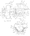
- FIG. 1 shows one from the document CH 611389 Known SSenzentrifugalradpumpe 1 comprising a housing 3 with a Saugkonusgepuruseteil 3a and a spiral housing part 3b, within which an impeller 2 is rotatably mounted about a rotational axis 2d.
- the impeller 2 is driven by a motor, not shown, via the pump shaft 4 in the direction of rotation 4a, so that a conveyed by the Zentrifugalradpumpe 1 liquid is conveyed in the flow direction S flowing from the inlet opening 3c to the outlet opening 3c, wherein the impeller 2, a blade pressure side a and a Bucket suction side b forms.
- the impeller 2 has a blade 2a with blade edge 2b, wherein a gap c is formed between the suction cone housing part 3a and the blade edge 2b, in the region of which a backflow from the blade pressure side a to the blade suction side b occurs.
- the gap c increases with increasing wear of the blade edge 2b, which reduces the delivery rate and the efficiency of the Zentrifugalradpumpe 1.
- FIG. 2 shows a side view of the centrifugal wheel pump 1 according to the invention, comprising a housing 3 with inlet opening 3c and outlet opening 3d, and comprising a wear part 5 rotatably arranged within the housing 3 about the axis of rotation 2d in the direction of rotation e.
- the section shown in Figure 3 along the section line AA and the section shown in Figure 4 along the section line BB according to Figure 2 shows the Zentrifugalradpumpe 1 with housing 3, inlet opening 3c and outlet opening 3d, and disposed within the housing 3 impeller 2 and within The impeller 2 is fixedly connected to the pump shaft 4, and rotatably supported by this about a rotational axis 2d.
- the wear part 5 surrounds the impeller 2 as shown, wherein the wear part 5 is mounted with respect to the housing 3, that a rotation of the Verschleissteils 5 causes in the circumferential direction to the rotation axis 2d, or in the direction e, a displacement of the Verschleissteils 5 in the direction of rotation of the rotation axis 2d ,
- the Verschleissteil 5 has a transverse to the direction of rotation of the axis of rotation 2d groove 5d, which is mounted in a projecting pin 6 of the housing 3, so that rotation of the Verschleissteils 5 forces a displacement of the Verschleissteils 5 in the direction of the axis of rotation 2d.
- These screws 7b extend, as shown in Figure 2, through the housing 3.
- the housing 3 preferably has a thread for receiving the screw 7b, so that the screw head is outside the housing 3, and thus the screw 7b from outside the housing. 3 can be rotated, wherein the support point 7a acts within the housing 3 on the cam 5e.
- the housing 3 as shown in Figure 2, counteracting the wear part 5 acting Screws 7b arranged.
- the wear part 5 can be very precisely rotated by a, if necessary, larger angular range of for example up to 45 degrees, the screws 7b are tightened again after turning the Verschleissteils 5, that the support points 7a of both screws 7b bears against a respective cam 5e of the wearing part 5, so that the wearing part 5 is secured in the housing 3 with respect to rotation.
- the wear part 5, as shown in Figure 4, two cylindrical outer contours 5g, 5h and the pump housing 3 has two cylindrical inner contours 3g, 3h, each forming a running in the direction of the axis of rotation 2d seat 53a, 53b, wherein these two seats 53a, 53b are arranged spaced apart in the direction of the rotation axis 2d, so that the wear part 5 is defined and guided in the direction of progression of the rotation axis 2d.
- a circumferential groove 8 is also arranged in the housing 3 and / or in the wear part 5 as shown, in which advantageously a sealing ring is arranged to seal, as shown in Figure 4, the interior between the two grooves 8.
- Figure 5 shows a detail aspect of Figure 4 in an enlarged view.
- the wear part 5 is through the two seats 53a, 53b slidably mounted in the direction d.
- a rotation of the wear part 5 causes, by the, as shown in Figure 4, in the grooves 5 d engaging guide pins 6, a displacement of the Verschleissteils 5 in the direction d.
- the wear part 5 has a portion whose inner surface 5f extends in accordance with the outer contour of the blade 2a, so that a gap c is formed between the blade edge 2b and the inner surface 5f.
- FIG. 6 shows the closure part 5 in a perspective view.
- the wear part 5 comprises in each case a hollow cylindrical section 5b, 5c with a cylindrical outer contour 5g, 5h, and a conical section 5a, as well as two protruding cams 5e and two grooves 5d, only one of the grooves 5d being visible.
- This groove 5d for example, has a constant pitch, but may also have different or variable pitches.
- the groove 5d, as shown in Figure 6, a helically extending portion.
- the adjusting means 7 could also comprise an electrically or mechanically driven drive device.
- the pump 1 shown in FIG. 2 has, instead of a screw 7b, an adjusting means 7 designed as a linear motor, which is arranged completely inside the housing 3.
- the two adjusting means 7 can be actuated externally via an electrically conductive cable 7c.
Abstract
Description
Die Erfindung betrifft eine Zentrifugalradpumpe gemäss dem Oberbegriff von Anspruch 1.The invention relates to a centrifugal pump according to the preamble of
Aus der Druckschrift
Der Erfindung liegt die Aufgabe zugrunde eine Zentrifugalradpumpe zu schaffen, deren sich verschleissende Laufradkante sich geringer auf den Wirkungsrad der Pumpe auswirkt.The invention has for its object to provide a Zentrifugalradpumpe whose wearing wheel edge affects less on the Wirkungsrad the pump.
Diese Aufgabe wird gelöst mit einer Zentrifugalradpumpe aufweisend die Merkmale von Anspruch 1. Die Unteransprüche 2 bis 11 betreffen weitere, vorteilhafte Ausgestaltungen. Die Aufgabe wird weiter gelöst mit einem Verfahren aufweisend die Merkmale von Anspruch 12.This object is achieved with a Zentrifugalradpumpe having the features of
Die Aufgabe wird insbesondere gelöst mit einer Zentrifugalradpumpe umfassend ein Pumpengehäuse sowie ein darin angeordnetes Laufrad, wobei das Laufrad um eine Drehachse drehbar gelagert ist, und wobei das Laufrad zumindest eine Schaufel mit einer Schaufelkante aufweist, und wobei innerhalb des Pumpengehäuses ein die Schaufelkante derart umschliessendes, sich in Verlaufsrichtung der Drehachse erweiterndes Verschleissteil angeordnet ist, dass das Verschleissteil bezüglich der Schaufelkante einen Spalt aufweist, und wobei das Verschleissteil derart bezüglich dem Pumpengehäuse verschiebbar gelagert ist, dass eine Drehen des Verschleissteils um die Drehachse ein Verschieben des Verschleissteils in Richtung der Drehachse bewirkt, um dadurch den Spalt zwischen Schaufelkante und Verschleissteil zu verändern.The object is achieved in particular with a centrifugal wheel pump comprising a pump housing and an impeller arranged therein, wherein the impeller is rotatably mounted about an axis of rotation, and wherein the impeller has at least one blade with a blade edge, and wherein within the pump housing a blade edge enclosing in such a way, is arranged extending in the direction of the axis of rotation wear part, that the wear part with respect to the blade edge has a gap, and wherein the wear part is slidably mounted relative to the pump housing such that rotating the Verschleissteils about the rotational axis causes a displacement of the Verschleissteils in the direction of the axis of rotation to thereby change the gap between the blade edge and the wear part.
In einer besonders vorteilhaften Ausgestaltung weist die Zentrifugalradpumpe ein Verstellmittel auf, welches von ausserhalb des Pumpengehäuses zugänglich ist, und welches ein Verdrehen des Verschleissteils erlaubt. Dies erlaubt den Spalt zwischen dem Verschleissteil und dem Laufrad von Aussen einzustellen. In einer vorteilhaften Ausgestaltung ist die Breite des Spaltes zwischen dem Verschleissteil und dem Laufrad während dem Betrieb der Zentrifugalradpumpe einstellbar.In a particularly advantageous embodiment, the Zentrifugalradpumpe on an adjustment, which is accessible from outside the pump housing, and which allows rotation of the Verschleissteils. This allows to set the gap between the wear part and the impeller from the outside. In an advantageous embodiment, the width of the gap between the Verschleissteil and the impeller during operation of the Zentrifugalradpumpe is adjustable.
Die erfindungsgemässe Zentrifugalradpumpe, umfassend das durch Drehen verstellbare Verschleissteil, kann auf unterschiedlichste Weise ausgestaltet sein, beispielsweise als Schraubenradzentrifugalradpumpe oder als Kreiselpumpe. Die Zentrifugalradpumpe kann auch ein Laufrad mit mehreren Schaufeln aufweisen. Die Zentrifugalradpumpe kann auch mehrere Laufräder aufweisen, wobei jedes Laufrad ein zugeordnetes Verschleissteil aufweist, und wobei zumindest ein Verschleissteil vorzugsweise individuell einstellbar ist.The centrifugal wheel pump according to the invention, comprising the wear part which can be adjusted by turning, can be used in many different ways Be configured manner, for example as Schraubradzentrifugalradpumpe or as a centrifugal pump. The Zentrifugalradpumpe may also have an impeller with a plurality of blades. The centrifugal wheel pump may also have a plurality of impellers, wherein each impeller has an associated wear part, and wherein at least one wear part is preferably individually adjustable.
Die Erfindung wird nachfolgend an Hand von Ausführungsbeispielen im Detail beschrieben. Dieselben Bezugszeichen bezeichnen dieselben Gegenstände. Es zeigen:
Figur 1- einen Axialschnitt durch eine bekannte Schraubenzentrifugalradpumpe;
Figur 2- eine Seitenansicht der erfindungsgemässen Schraubenzentrifugalradpumpe mit einer Draufsicht auf die Eintrittsöffnung;
Figur 3- einen Axialschnitt durch das Gehäuse der in
Figur 2 dargestellten Schraubenzentrifugalradpumpe entlang der Schnittlinie A-A; Figur 4- einen Axialschnitt durch das Gehäuse der in
Figur 2 dargestellten Schraubenzentrifugalradpumpe entlang der Schnittlinie B-B; Figur 5- eine Detailansicht der
Figur 4; Figur 6- eine perspektivische Ansicht eines Verschleissrings;
Figur 7- eine Seitenansicht eines weiteren Ausführungsbeispiels einer Zentrifugalradpumpe mit motorischer Verstellvorrichtung.
- FIG. 1
- an axial section through a known Schraubenzentrifugalradpumpe;
- FIG. 2
- a side view of the novel centrifugal centrifugal pump with a plan view of the inlet opening;
- FIG. 3
- an axial section through the housing of the screw centrifugal pump shown in Figure 2 along the section line AA;
- FIG. 4
- an axial section through the housing of the screw centrifugal pump shown in Figure 2 along the section line BB;
- FIG. 5
- a detailed view of Figure 4;
- FIG. 6
- a perspective view of a wear ring;
- FIG. 7
- a side view of another embodiment of a Zentrifugalradpumpe with motor adjustment.
Figur 1 zeigt eine aus der Druckschrift
Figur 2 zeigt eine Seitenansicht der erfindungsgemässen Zentrifugalradpumpe 1 umfassend ein Gehäuse 3 mit Eintrittsöffnung 3c und Austrittsöffnung 3d, sowie umfassend ein innerhalb des Gehäuses 3 um die Drehachse 2d in Drehrichtung e drehbar angeordnetes Verschleissteil 5.FIG. 2 shows a side view of the
Der in Figur 3 dargestellte Schnitt entlang der Schnittlinie A-A sowie der in Figur 4 dargestellte Schnitt entlang der Schnittlinie B-B gemäss Figur 2 zeigt die Zentrifugalradpumpe 1 mit Gehäuse 3, Eintrittsöffnung 3c und Austrittsöffnung 3d, sowie das innerhalb des Gehäuses 3 angeordnete Laufrad 2 und das innerhalb des Gehäuses 3 angeordnete Verschleissteil 5. Das Laufrad 2 ist mit der Pumpenwelle 4 fest verbunden, und durch diese um eine Drehachse 2d drehbar gelagert. Das Verschleissteil 5 umschliesst das Laufrad 2 wie dargestellt, wobei das Verschleissteil 5 derart bezüglich dem Gehäuse 3 gelagert ist, dass ein Drehen des Verschleissteils 5 in Umfangsrichtung zur Drehachse 2d, beziehungsweise in Richtung e, ein Verschieben des Verschleissteils 5 in Verlaufsrichtung der Drehachse 2d bewirkt. Im dargestellten Ausführungsbeispiel weist das Verschleissteil 5 eine quer zur Verlaufsrichtung der Drehachse 2d verlaufende Nut 5d auf, welche in einem vorstehenden Stift 6 des Gehäuses 3 gelagert ist, sodass ein Drehen des Verschleissteils 5 ein Verschieben des Verschleissteils 5 in Richtung der Drehachse 2d erzwingt. Im dargestellten Ausführungsbeispiel weist das Verschleissteil 5, wie aus den Figuren 2 und 4 ersichtlich, zwei gegenüberliegende, vorstehende Nocken 5e auf, auf welche je ein Verstellmittel 7, im dargestellten Ausführungsbeispiel ausgestaltet als Schraube 7b, über eine Auflagestelle 7a einwirkt. Diese Schrauben 7b verlaufen, wie aus Figur 2 ersichtlich, durch das Gehäuse 3. Das Gehäuse 3 weist vorzugsweise ein Gewinde zur Aufnahme der Schraube 7b auf, sodass sich der Schraubenkopf ausserhalb des Gehäuses 3 befindet, und somit die Schraube 7b von ausserhalb des Gehäuses 3 gedreht werden kann, wobei die Auflagestelle 7a innerhalb des Gehäuses 3 auf die Nocke 5e einwirkt. In einer vorteilhaften Ausgestaltung sind im Gehäuse 3, wie in Figur 2 dargestellt, gegengleich auf das Verschleissteil 5 wirkende Schrauben 7b angeordnet. Um das Verschleissteil 5 in der Pumpe 1 zu drehen, und somit in Richtung d zu verschieben, ist somit zuerst eine Schraube 7 zu lösen und daraufhin die anderen Schraube 7 anzuziehen, was ein Verdrehen des Verschleissteils 5 und somit ein Verschieben des Verschleissteils 5 in Verlaufsrichtung der Drehachse 2d beziehungsweise in Richtung d bewirkt. Durch ein entsprechendes Lösen und wieder Anziehen der beiden Schrauben 7b kann das Verschleissteil 5 sehr präzise um einen , falls erforderlich, grösseren Winkelbereich von beispielsweise bis zu 45 Grad gedreht werden, wobei die Schrauben 7b nach dem Drehen des Verschleissteils 5 wieder derart angezogen werden, dass die Auflagestellen 7a beider Schrauben 7b an je einer Nocke 5e des Verschleissteil 5 anliegt, sodass das Verschleissteil 5 bezüglich Verdrehen gesichert im Gehäuse 3 gehalten ist.The section shown in Figure 3 along the section line AA and the section shown in Figure 4 along the section line BB according to Figure 2 shows the
In einer vorteilhaften Ausgestaltung weist das Verschleissteil 5, wie in Figur 4 dargestellt, zwei zylinderförmig verlaufende Aussenkonturen 5g, 5h und das Pumpengehäuse 3 zwei zylinderförmig verlaufende Innenkonturen 3g,3h auf, welche je einen in Richtung der Drehachse 2d verlaufenden Sitz 53a, 53b ausbilden, wobei diese beide Sitze 53a, 53b in Richtung der Drehachse 2d beabstandet angeordnet sind, sodass das Verschleissteil 5 in Verlaufsrichtung der Drehachse 2d definiert und geführt gelagert ist. In einer vorteilhaften Ausgestaltung ist zudem im Gehäuse 3 und/oder im Verschleissteil 5 wie dargestellt eine umlaufende Nut 8 angeordnet, in welcher vorteilhafterweise ein Dichtungsring angeordnet ist, um, wie in Figur 4 dargestellt, den Innenraum zwischen den zwei Nuten 8 abzudichten.In an advantageous embodiment, the
Figur 5 zeigt ein Detailaspekt von Figur 4 in vergrösserter Darstellung. Das Verschleissteil 5 ist durch die beiden Sitze 53a, 53b in Richtung d verschiebbar gelagert. Ein Drehen des Verschleissteils 5 bewirkt durch die, wie in Figur 4 dargestellt, in die Nuten 5d eingreifenden Führungsstifte 6, ein Verschieben des Verschleissteils 5 in Richtung d. Das Verschleissteil 5 weist einen Abschnitt auf, dessen Innenfläche 5f entsprechend der Aussenkontur der Schaufel 2a verläuft, sodass sich zwischen der Schaufelkante 2b und der Innenfläche 5f ein Spalt c ausbildet. In einer vorteilhaften Ausgestaltung ist der Abschnitt 5a des Verschleissteils 5, wie in Figur 5 dargestellt, mit einer konusförmig verlaufenen Innenfläche 5f versehen, wobei die Aussenkontur des sich in diesem Abschnitt befindlichen Teils der Schaufel 2a ebenfalls eine konusförmige Aussenkontur aufweist. Durch ein Verschieben des Verschleissteils 5 in Richtung d kann somit die Breite des Spaltes c verändert werden.Figure 5 shows a detail aspect of Figure 4 in an enlarged view. The
Figur 6 zeigt das Verschliessteil 5 in einer perspektivischen Ansicht. Das Verschleissteil 5 umfasst je einen hohlzylinderförmigen Abschnitt 5b, 5c mit zylinderförmiger Aussenkontur 5g, 5h, sowie einen konusförmigen Abschnitt 5a, sowie zwei vorstehende Nocken 5e sowie zwei Nuten 5d, wobei nur eine der Nuten 5d sichtbar ist. Diese Nut 5d weist beispielsweise eine konstante Steigung auf, kann jedoch auch unterschiedliche oder eine veränderliche Steigungen aufweisen. In einer vorteilhaften Ausgestaltung weist die Nut 5d, wie in Figur 6 dargestellt, einen wendelförmig verlaufenden Teilabschnitt auf. In einer vorteilhaften Ausgestaltung weist die Nut 5d, wie in Figur 3 dargestellt, in Drehrichtung 4a eine sich vom Laufrad entfernende Steigung auf. Die ergibt folgenden Vorteil: Sollte das Laufrad 2 das Verschleissteil 5 berühren und ev. mitnehmen, so wird das Verschleissteil 5 derart verdreht, dass sich dieses auf Grund des Verlaufes der Nut 5d vom Laufrad 2 weg bewegt, sodass das Laufrad 2 den Kontakt zum Verschleissteil 5 verliert.FIG. 6 shows the
Das Verstellmittel 7 könnte auch eine elektrisch oder mechanisch angetriebene Antriebsvorrichtung umfassen. Die in Figur 7 dargestellte Pumpe 1 weist im Unterschied zu der in Figur 2 dargestellten Ausführungsform an Stelle einer Schraube 7b ein als Linearmotor ausgestaltetes Verstellmittel 7 auf, welches vollständig innerhalb des Gehäuses 3 angeordnet ist. Die beiden Verstellmittel 7 sind über ein elektrisch leitendes Kabel 7c von Aussen ansteuerbar.The adjusting means 7 could also comprise an electrically or mechanically driven drive device. In contrast to the embodiment shown in FIG. 2, the
Claims (12)
Priority Applications (6)
| Application Number | Priority Date | Filing Date | Title |
|---|---|---|---|
| EP06121159A EP1906025A1 (en) | 2006-09-22 | 2006-09-22 | Centrifugal pump |
| CN2007101480311A CN101149055B (en) | 2006-09-22 | 2007-08-29 | Impeller centrifugal pump and method for changing its wear part location |
| EP07116609A EP1906026B1 (en) | 2006-09-22 | 2007-09-17 | Centrifugal pump |
| DE502007002982T DE502007002982D1 (en) | 2006-09-22 | 2007-09-17 | Zentrifugalradpumpe |
| DK07116609.4T DK1906026T3 (en) | 2006-09-22 | 2007-09-17 | Centrifugal |
| AT07116609T ATE459803T1 (en) | 2006-09-22 | 2007-09-17 | CENTRIFUGAL WHEEL PUMP |
Applications Claiming Priority (1)
| Application Number | Priority Date | Filing Date | Title |
|---|---|---|---|
| EP06121159A EP1906025A1 (en) | 2006-09-22 | 2006-09-22 | Centrifugal pump |
Publications (1)
| Publication Number | Publication Date |
|---|---|
| EP1906025A1 true EP1906025A1 (en) | 2008-04-02 |
Family
ID=37759273
Family Applications (2)
| Application Number | Title | Priority Date | Filing Date |
|---|---|---|---|
| EP06121159A Withdrawn EP1906025A1 (en) | 2006-09-22 | 2006-09-22 | Centrifugal pump |
| EP07116609A Not-in-force EP1906026B1 (en) | 2006-09-22 | 2007-09-17 | Centrifugal pump |
Family Applications After (1)
| Application Number | Title | Priority Date | Filing Date |
|---|---|---|---|
| EP07116609A Not-in-force EP1906026B1 (en) | 2006-09-22 | 2007-09-17 | Centrifugal pump |
Country Status (5)
| Country | Link |
|---|---|
| EP (2) | EP1906025A1 (en) |
| CN (1) | CN101149055B (en) |
| AT (1) | ATE459803T1 (en) |
| DE (1) | DE502007002982D1 (en) |
| DK (1) | DK1906026T3 (en) |
Cited By (4)
| Publication number | Priority date | Publication date | Assignee | Title |
|---|---|---|---|---|
| DE102012023734A1 (en) * | 2012-12-05 | 2014-06-05 | Wilo Se | Centrifugal pump especially for sewage or dirty water |
| EP2908012A3 (en) * | 2014-01-24 | 2015-12-30 | McFinn Technologies | Radial impeller and casing for centrifugal pump |
| EP3447308A1 (en) * | 2008-06-13 | 2019-02-27 | Weir Minerals Australia Ltd | Adjustable side liner for a pump |
| EP4001665A1 (en) * | 2018-06-12 | 2022-05-25 | Wilo Se | Centrifugal pump with a pump housing |
Families Citing this family (5)
| Publication number | Priority date | Publication date | Assignee | Title |
|---|---|---|---|---|
| AU2013202757B2 (en) * | 2008-06-13 | 2014-05-15 | Weir Minerals Australia Ltd | An adjustable side liner for a pump |
| AU2015202357B2 (en) * | 2008-06-13 | 2017-02-02 | Weir Minerals Australia Ltd | An adjustable side liner for a pump |
| CN106762784A (en) * | 2016-12-06 | 2017-05-31 | 芜湖市容川机电科技股份有限公司 | Spheroidal graphite cast-iron drilling platforms high pressure cylinders |
| JP7124422B2 (en) * | 2018-04-27 | 2022-08-24 | 株式会社アイシン | pump |
| CN110594163A (en) * | 2019-10-21 | 2019-12-20 | 海斯特(青岛)泵业有限公司 | Water pump with forced feeding mechanism |
Citations (6)
| Publication number | Priority date | Publication date | Assignee | Title |
|---|---|---|---|---|
| GB215961A (en) * | 1923-05-16 | 1924-05-22 | W H Allen Sons & Company Ltd | Improvements in centrifugal pumps |
| FR2134063A1 (en) * | 1972-04-28 | 1972-12-01 | Renaud Georges | |
| FR2290133A6 (en) * | 1973-02-09 | 1976-05-28 | Materiel Processing Internal | Centrifugal pump with sealing plate - has inner part of plate movable in axial direction of impeller |
| DE2642231A1 (en) * | 1975-10-02 | 1977-04-14 | Martin Staehle | SINGLE BLADE CENTRIFUGAL PUMP FOR PUMPING VISUAL LIQUIDS, IN PARTICULAR SOLIDS |
| FR2681906A1 (en) * | 1991-09-27 | 1993-04-02 | Renault Vehicules Ind | Centrifugal pump for a combustion engine coolant circuit |
| DE29608236U1 (en) * | 1996-05-07 | 1996-08-01 | Kleindienst Uwe | Centrifugal pump |
Family Cites Families (3)
| Publication number | Priority date | Publication date | Assignee | Title |
|---|---|---|---|---|
| US4037985A (en) * | 1976-05-20 | 1977-07-26 | Worthington Pump, Inc. | Flushing liquid system for the wearing ring in centrifugal pumps and the wearing ring assembly and wearing ring for use therein |
| CN2606202Y (en) * | 2003-03-10 | 2004-03-10 | 宜兴市宙斯泵业有限公司 | Improved two-stage centrifugal pumps |
| CN2802133Y (en) * | 2005-07-05 | 2006-08-02 | 宜兴市宙斯泵业有限公司 | Corrision-resisting, wear-resisting front cover of centrifugal pump |
-
2006
- 2006-09-22 EP EP06121159A patent/EP1906025A1/en not_active Withdrawn
-
2007
- 2007-08-29 CN CN2007101480311A patent/CN101149055B/en not_active Expired - Fee Related
- 2007-09-17 DE DE502007002982T patent/DE502007002982D1/en active Active
- 2007-09-17 AT AT07116609T patent/ATE459803T1/en active
- 2007-09-17 DK DK07116609.4T patent/DK1906026T3/en active
- 2007-09-17 EP EP07116609A patent/EP1906026B1/en not_active Not-in-force
Patent Citations (6)
| Publication number | Priority date | Publication date | Assignee | Title |
|---|---|---|---|---|
| GB215961A (en) * | 1923-05-16 | 1924-05-22 | W H Allen Sons & Company Ltd | Improvements in centrifugal pumps |
| FR2134063A1 (en) * | 1972-04-28 | 1972-12-01 | Renaud Georges | |
| FR2290133A6 (en) * | 1973-02-09 | 1976-05-28 | Materiel Processing Internal | Centrifugal pump with sealing plate - has inner part of plate movable in axial direction of impeller |
| DE2642231A1 (en) * | 1975-10-02 | 1977-04-14 | Martin Staehle | SINGLE BLADE CENTRIFUGAL PUMP FOR PUMPING VISUAL LIQUIDS, IN PARTICULAR SOLIDS |
| FR2681906A1 (en) * | 1991-09-27 | 1993-04-02 | Renault Vehicules Ind | Centrifugal pump for a combustion engine coolant circuit |
| DE29608236U1 (en) * | 1996-05-07 | 1996-08-01 | Kleindienst Uwe | Centrifugal pump |
Cited By (6)
| Publication number | Priority date | Publication date | Assignee | Title |
|---|---|---|---|---|
| EP3447308A1 (en) * | 2008-06-13 | 2019-02-27 | Weir Minerals Australia Ltd | Adjustable side liner for a pump |
| DE102012023734A1 (en) * | 2012-12-05 | 2014-06-05 | Wilo Se | Centrifugal pump especially for sewage or dirty water |
| US9869326B2 (en) | 2012-12-05 | 2018-01-16 | Wilo Se | Centrifugal pump in particular for waste water or polluted water |
| EP2908012A3 (en) * | 2014-01-24 | 2015-12-30 | McFinn Technologies | Radial impeller and casing for centrifugal pump |
| US10094384B2 (en) | 2014-01-24 | 2018-10-09 | Mcfinn Technologies, Llc | Radial impeller and casing for centrifugal pump |
| EP4001665A1 (en) * | 2018-06-12 | 2022-05-25 | Wilo Se | Centrifugal pump with a pump housing |
Also Published As
| Publication number | Publication date |
|---|---|
| CN101149055B (en) | 2010-11-17 |
| ATE459803T1 (en) | 2010-03-15 |
| DE502007002982D1 (en) | 2010-04-15 |
| EP1906026B1 (en) | 2010-03-03 |
| CN101149055A (en) | 2008-03-26 |
| EP1906026A1 (en) | 2008-04-02 |
| DK1906026T3 (en) | 2010-05-31 |
Similar Documents
| Publication | Publication Date | Title |
|---|---|---|
| EP1906026B1 (en) | Centrifugal pump | |
| EP2929191B1 (en) | Centrifugal pump in particular for waste water or polluted water | |
| EP3019276B1 (en) | Agitator ball mill with axial channels | |
| DE1800888A1 (en) | Pump seal | |
| EP1584820B1 (en) | Mixed flow pump | |
| DE1703139B1 (en) | Control device for a radial centrifugal pump | |
| DE2166624A1 (en) | DEVICE FOR CRUSHING SOLIDS FLOATING WITH A LIQUID | |
| DE4428633C2 (en) | Peripheral pump for supplying fuel to a vehicle engine | |
| DE2313403A1 (en) | AXIAL FLOW MACHINE | |
| WO2013127534A1 (en) | Device for mixing at least two fluid components, rotary-driven mixer insert therefor, and system of the two | |
| WO2021170471A1 (en) | Filter housing of a brake dust particle filter for a brake disk arrangement and kit for a filter housing of a brake dust particle filter | |
| EP2458225A1 (en) | Covering board for a screw centrifuge wheel pump and screw centrifuge wheel pump comprising such a covering board | |
| DE4208202A1 (en) | CENTRIFUGAL PUMP | |
| WO2006131425A1 (en) | Helical conveyor centrifuge | |
| DE102008057849A1 (en) | Cutting device for e.g. sewage pump, has cutting body coaxially surrounded by fixed cutting ring, where annular gap between cutting body and ring decreases in its width from inlet aperture to rotor in opening region close to pump inlet | |
| DE20307420U1 (en) | Blade with detachable tail | |
| DE3412873C2 (en) | Pump, especially barrel pump | |
| EP3498365A1 (en) | Stirrer device | |
| EP2138723B1 (en) | Centrifugal pump with free flow wheel | |
| EP1187991B1 (en) | Delivery pump | |
| EP3388671A1 (en) | Impeller pump | |
| EP3250434B1 (en) | Cellular rotary valve and sanding system for a rail vehicle having improved response behavior | |
| WO2020058081A1 (en) | Pump assembly | |
| DE2459712A1 (en) | PUMP ARRANGEMENT FOR REGULATING THE FLOW RATE OF A LIQUID IN A PIPING SYSTEM | |
| DE239731C (en) |
Legal Events
| Date | Code | Title | Description |
|---|---|---|---|
| PUAI | Public reference made under article 153(3) epc to a published international application that has entered the european phase |
Free format text: ORIGINAL CODE: 0009012 |
|
| AK | Designated contracting states |
Kind code of ref document: A1 Designated state(s): AT BE BG CH CY CZ DE DK EE ES FI FR GB GR HU IE IS IT LI LT LU LV MC NL PL PT RO SE SI SK TR |
|
| AX | Request for extension of the european patent |
Extension state: AL BA HR MK YU |
|
| AKX | Designation fees paid | ||
| REG | Reference to a national code |
Ref country code: DE Ref legal event code: 8566 |
|
| STAA | Information on the status of an ep patent application or granted ep patent |
Free format text: STATUS: THE APPLICATION IS DEEMED TO BE WITHDRAWN |
|
| 18D | Application deemed to be withdrawn |
Effective date: 20081003 |