EP1906025A1 - Pompe centrifuge - Google Patents
Pompe centrifuge Download PDFInfo
- Publication number
- EP1906025A1 EP1906025A1 EP06121159A EP06121159A EP1906025A1 EP 1906025 A1 EP1906025 A1 EP 1906025A1 EP 06121159 A EP06121159 A EP 06121159A EP 06121159 A EP06121159 A EP 06121159A EP 1906025 A1 EP1906025 A1 EP 1906025A1
- Authority
- EP
- European Patent Office
- Prior art keywords
- rotation
- axis
- zentrifugalradpumpe
- pump housing
- wear part
- Prior art date
- Legal status (The legal status is an assumption and is not a legal conclusion. Google has not performed a legal analysis and makes no representation as to the accuracy of the status listed.)
- Withdrawn
Links
Images


Classifications
-
- F—MECHANICAL ENGINEERING; LIGHTING; HEATING; WEAPONS; BLASTING
- F04—POSITIVE - DISPLACEMENT MACHINES FOR LIQUIDS; PUMPS FOR LIQUIDS OR ELASTIC FLUIDS
- F04D—NON-POSITIVE-DISPLACEMENT PUMPS
- F04D7/00—Pumps adapted for handling specific fluids, e.g. by selection of specific materials for pumps or pump parts
- F04D7/02—Pumps adapted for handling specific fluids, e.g. by selection of specific materials for pumps or pump parts of centrifugal type
- F04D7/04—Pumps adapted for handling specific fluids, e.g. by selection of specific materials for pumps or pump parts of centrifugal type the fluids being viscous or non-homogenous
-
- F—MECHANICAL ENGINEERING; LIGHTING; HEATING; WEAPONS; BLASTING
- F04—POSITIVE - DISPLACEMENT MACHINES FOR LIQUIDS; PUMPS FOR LIQUIDS OR ELASTIC FLUIDS
- F04D—NON-POSITIVE-DISPLACEMENT PUMPS
- F04D15/00—Control, e.g. regulation, of pumps, pumping installations or systems
- F04D15/0027—Varying behaviour or the very pump
- F04D15/0033—By-passing by increasing clearance between impeller and its casing
-
- F—MECHANICAL ENGINEERING; LIGHTING; HEATING; WEAPONS; BLASTING
- F04—POSITIVE - DISPLACEMENT MACHINES FOR LIQUIDS; PUMPS FOR LIQUIDS OR ELASTIC FLUIDS
- F04D—NON-POSITIVE-DISPLACEMENT PUMPS
- F04D29/00—Details, component parts, or accessories
- F04D29/08—Sealings
- F04D29/16—Sealings between pressure and suction sides
- F04D29/165—Sealings between pressure and suction sides especially adapted for liquid pumps
- F04D29/167—Sealings between pressure and suction sides especially adapted for liquid pumps of a centrifugal flow wheel
-
- F—MECHANICAL ENGINEERING; LIGHTING; HEATING; WEAPONS; BLASTING
- F04—POSITIVE - DISPLACEMENT MACHINES FOR LIQUIDS; PUMPS FOR LIQUIDS OR ELASTIC FLUIDS
- F04D—NON-POSITIVE-DISPLACEMENT PUMPS
- F04D29/00—Details, component parts, or accessories
- F04D29/40—Casings; Connections of working fluid
- F04D29/42—Casings; Connections of working fluid for radial or helico-centrifugal pumps
- F04D29/426—Casings; Connections of working fluid for radial or helico-centrifugal pumps especially adapted for liquid pumps
- F04D29/4286—Casings; Connections of working fluid for radial or helico-centrifugal pumps especially adapted for liquid pumps inside lining, e.g. rubber
-
- F—MECHANICAL ENGINEERING; LIGHTING; HEATING; WEAPONS; BLASTING
- F04—POSITIVE - DISPLACEMENT MACHINES FOR LIQUIDS; PUMPS FOR LIQUIDS OR ELASTIC FLUIDS
- F04D—NON-POSITIVE-DISPLACEMENT PUMPS
- F04D29/00—Details, component parts, or accessories
- F04D29/60—Mounting; Assembling; Disassembling
- F04D29/62—Mounting; Assembling; Disassembling of radial or helico-centrifugal pumps
- F04D29/622—Adjusting the clearances between rotary and stationary parts
-
- F—MECHANICAL ENGINEERING; LIGHTING; HEATING; WEAPONS; BLASTING
- F04—POSITIVE - DISPLACEMENT MACHINES FOR LIQUIDS; PUMPS FOR LIQUIDS OR ELASTIC FLUIDS
- F04D—NON-POSITIVE-DISPLACEMENT PUMPS
- F04D29/00—Details, component parts, or accessories
- F04D29/60—Mounting; Assembling; Disassembling
- F04D29/62—Mounting; Assembling; Disassembling of radial or helico-centrifugal pumps
- F04D29/628—Mounting; Assembling; Disassembling of radial or helico-centrifugal pumps especially adapted for liquid pumps
Definitions
- the invention relates to a centrifugal pump according to the preamble of claim 1.
- Such a centrifugal pump or Zentrifugalradpumpe comprises a single, helically extending blade, which is rotatably arranged in a pump housing.
- This pump is particularly suitable for the promotion of interspersed with solid admixtures liquids and especially for liquids containing abrasive admixtures.
- This pump has a gap between the impeller edge of the blade and the pump housing. With increasing wear of the impeller edge this gap increases, so that the sealing effect between impeller edge and pump housing is reduced, whereby the efficiency of the pump is reduced.
- the invention has for its object to provide a Zentrifugalradpumpe whose wearing wheel edge affects less on thegesrad the pump.
- a centrifugal wheel pump comprising a pump housing and an impeller arranged therein, wherein the impeller is rotatably mounted about an axis of rotation, and wherein the impeller has at least one blade with a blade edge, and wherein within the pump housing a blade edge enclosing in such a way, is arranged extending in the direction of the axis of rotation wear part, that the wear part with respect to the blade edge has a gap, and wherein the wear part is slidably mounted relative to the pump housing such that rotating the Verschleissteils about the rotational axis causes a displacement of the Verschleissteils in the direction of the axis of rotation to thereby change the gap between the blade edge and the wear part.
- the Zentrifugalradpumpe on an adjustment, which is accessible from outside the pump housing, and which allows rotation of the Verschleissteils. This allows to set the gap between the wear part and the impeller from the outside.
- the width of the gap between the Verschleissteil and the impeller during operation of the Zentrifugalradpumpe is adjustable.
- the centrifugal wheel pump according to the invention comprising the wear part which can be adjusted by turning, can be used in many different ways Be configured manner, for example as SSradzentrifugalradpumpe or as a centrifugal pump.
- the Zentrifugalradpumpe may also have an impeller with a plurality of blades.
- the centrifugal wheel pump may also have a plurality of impellers, wherein each impeller has an associated wear part, and wherein at least one wear part is preferably individually adjustable.
- FIG. 1 shows one from the document CH 611389 Known SSenzentrifugalradpumpe 1 comprising a housing 3 with a Saugkonusgepuruseteil 3a and a spiral housing part 3b, within which an impeller 2 is rotatably mounted about a rotational axis 2d.
- the impeller 2 is driven by a motor, not shown, via the pump shaft 4 in the direction of rotation 4a, so that a conveyed by the Zentrifugalradpumpe 1 liquid is conveyed in the flow direction S flowing from the inlet opening 3c to the outlet opening 3c, wherein the impeller 2, a blade pressure side a and a Bucket suction side b forms.
- the impeller 2 has a blade 2a with blade edge 2b, wherein a gap c is formed between the suction cone housing part 3a and the blade edge 2b, in the region of which a backflow from the blade pressure side a to the blade suction side b occurs.
- the gap c increases with increasing wear of the blade edge 2b, which reduces the delivery rate and the efficiency of the Zentrifugalradpumpe 1.
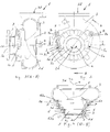
- FIG. 2 shows a side view of the centrifugal wheel pump 1 according to the invention, comprising a housing 3 with inlet opening 3c and outlet opening 3d, and comprising a wear part 5 rotatably arranged within the housing 3 about the axis of rotation 2d in the direction of rotation e.
- the section shown in Figure 3 along the section line AA and the section shown in Figure 4 along the section line BB according to Figure 2 shows the Zentrifugalradpumpe 1 with housing 3, inlet opening 3c and outlet opening 3d, and disposed within the housing 3 impeller 2 and within The impeller 2 is fixedly connected to the pump shaft 4, and rotatably supported by this about a rotational axis 2d.
- the wear part 5 surrounds the impeller 2 as shown, wherein the wear part 5 is mounted with respect to the housing 3, that a rotation of the Verschleissteils 5 causes in the circumferential direction to the rotation axis 2d, or in the direction e, a displacement of the Verschleissteils 5 in the direction of rotation of the rotation axis 2d ,
- the Verschleissteil 5 has a transverse to the direction of rotation of the axis of rotation 2d groove 5d, which is mounted in a projecting pin 6 of the housing 3, so that rotation of the Verschleissteils 5 forces a displacement of the Verschleissteils 5 in the direction of the axis of rotation 2d.
- These screws 7b extend, as shown in Figure 2, through the housing 3.
- the housing 3 preferably has a thread for receiving the screw 7b, so that the screw head is outside the housing 3, and thus the screw 7b from outside the housing. 3 can be rotated, wherein the support point 7a acts within the housing 3 on the cam 5e.
- the housing 3 as shown in Figure 2, counteracting the wear part 5 acting Screws 7b arranged.
- the wear part 5 can be very precisely rotated by a, if necessary, larger angular range of for example up to 45 degrees, the screws 7b are tightened again after turning the Verschleissteils 5, that the support points 7a of both screws 7b bears against a respective cam 5e of the wearing part 5, so that the wearing part 5 is secured in the housing 3 with respect to rotation.
- the wear part 5, as shown in Figure 4, two cylindrical outer contours 5g, 5h and the pump housing 3 has two cylindrical inner contours 3g, 3h, each forming a running in the direction of the axis of rotation 2d seat 53a, 53b, wherein these two seats 53a, 53b are arranged spaced apart in the direction of the rotation axis 2d, so that the wear part 5 is defined and guided in the direction of progression of the rotation axis 2d.
- a circumferential groove 8 is also arranged in the housing 3 and / or in the wear part 5 as shown, in which advantageously a sealing ring is arranged to seal, as shown in Figure 4, the interior between the two grooves 8.
- Figure 5 shows a detail aspect of Figure 4 in an enlarged view.
- the wear part 5 is through the two seats 53a, 53b slidably mounted in the direction d.
- a rotation of the wear part 5 causes, by the, as shown in Figure 4, in the grooves 5 d engaging guide pins 6, a displacement of the Verschleissteils 5 in the direction d.
- the wear part 5 has a portion whose inner surface 5f extends in accordance with the outer contour of the blade 2a, so that a gap c is formed between the blade edge 2b and the inner surface 5f.
- FIG. 6 shows the closure part 5 in a perspective view.
- the wear part 5 comprises in each case a hollow cylindrical section 5b, 5c with a cylindrical outer contour 5g, 5h, and a conical section 5a, as well as two protruding cams 5e and two grooves 5d, only one of the grooves 5d being visible.
- This groove 5d for example, has a constant pitch, but may also have different or variable pitches.
- the groove 5d, as shown in Figure 6, a helically extending portion.
- the adjusting means 7 could also comprise an electrically or mechanically driven drive device.
- the pump 1 shown in FIG. 2 has, instead of a screw 7b, an adjusting means 7 designed as a linear motor, which is arranged completely inside the housing 3.
- the two adjusting means 7 can be actuated externally via an electrically conductive cable 7c.
Priority Applications (6)
| Application Number | Priority Date | Filing Date | Title |
|---|---|---|---|
| EP06121159A EP1906025A1 (fr) | 2006-09-22 | 2006-09-22 | Pompe centrifuge |
| CN2007101480311A CN101149055B (zh) | 2006-09-22 | 2007-08-29 | 叶轮离心泵和改变其耐磨件的位置的方法 |
| AT07116609T ATE459803T1 (de) | 2006-09-22 | 2007-09-17 | Zentrifugalradpumpe |
| EP07116609A EP1906026B1 (fr) | 2006-09-22 | 2007-09-17 | Pompe à roue centrifuge |
| DK07116609.4T DK1906026T3 (da) | 2006-09-22 | 2007-09-17 | Centrifugalpumpe |
| DE502007002982T DE502007002982D1 (de) | 2006-09-22 | 2007-09-17 | Zentrifugalradpumpe |
Applications Claiming Priority (1)
| Application Number | Priority Date | Filing Date | Title |
|---|---|---|---|
| EP06121159A EP1906025A1 (fr) | 2006-09-22 | 2006-09-22 | Pompe centrifuge |
Publications (1)
| Publication Number | Publication Date |
|---|---|
| EP1906025A1 true EP1906025A1 (fr) | 2008-04-02 |
Family
ID=37759273
Family Applications (2)
| Application Number | Title | Priority Date | Filing Date |
|---|---|---|---|
| EP06121159A Withdrawn EP1906025A1 (fr) | 2006-09-22 | 2006-09-22 | Pompe centrifuge |
| EP07116609A Not-in-force EP1906026B1 (fr) | 2006-09-22 | 2007-09-17 | Pompe à roue centrifuge |
Family Applications After (1)
| Application Number | Title | Priority Date | Filing Date |
|---|---|---|---|
| EP07116609A Not-in-force EP1906026B1 (fr) | 2006-09-22 | 2007-09-17 | Pompe à roue centrifuge |
Country Status (5)
| Country | Link |
|---|---|
| EP (2) | EP1906025A1 (fr) |
| CN (1) | CN101149055B (fr) |
| AT (1) | ATE459803T1 (fr) |
| DE (1) | DE502007002982D1 (fr) |
| DK (1) | DK1906026T3 (fr) |
Cited By (4)
| Publication number | Priority date | Publication date | Assignee | Title |
|---|---|---|---|---|
| DE102012023734A1 (de) * | 2012-12-05 | 2014-06-05 | Wilo Se | Kreiselpumpe insbesondere für Abwasser oder Schmutzwasser |
| EP2908012A3 (fr) * | 2014-01-24 | 2015-12-30 | McFinn Technologies | Turbine radiale et boîtier pour pompe centrifuge |
| EP3447308A1 (fr) * | 2008-06-13 | 2019-02-27 | Weir Minerals Australia Ltd | Doublure latérale réglable destinée à une pompe |
| EP4001665A1 (fr) * | 2018-06-12 | 2022-05-25 | Wilo Se | Pompe centrifuge dotée d'un carter de pompe |
Families Citing this family (5)
| Publication number | Priority date | Publication date | Assignee | Title |
|---|---|---|---|---|
| AU2013202758B2 (en) * | 2008-06-13 | 2014-06-19 | Weir Minerals Australia Ltd | An adjustable side liner for a pump |
| AU2015202357B2 (en) * | 2008-06-13 | 2017-02-02 | Weir Minerals Australia Ltd | An adjustable side liner for a pump |
| CN106762784A (zh) * | 2016-12-06 | 2017-05-31 | 芜湖市容川机电科技股份有限公司 | 球墨铸铁钻井平台高压泵体 |
| JP7124422B2 (ja) * | 2018-04-27 | 2022-08-24 | 株式会社アイシン | ポンプ |
| CN110594163A (zh) * | 2019-10-21 | 2019-12-20 | 海斯特(青岛)泵业有限公司 | 一种带有强制喂料机构的水泵 |
Citations (6)
| Publication number | Priority date | Publication date | Assignee | Title |
|---|---|---|---|---|
| GB215961A (en) * | 1923-05-16 | 1924-05-22 | W H Allen Sons & Company Ltd | Improvements in centrifugal pumps |
| FR2134063A1 (fr) * | 1972-04-28 | 1972-12-01 | Renaud Georges | |
| FR2290133A6 (fr) * | 1973-02-09 | 1976-05-28 | Materiel Processing Internal | Pompe centrifuge |
| DE2642231A1 (de) * | 1975-10-02 | 1977-04-14 | Martin Staehle | Einschaufel-zentrifugalpumpe zur foerderung von zaehfluessigen, insbesondere feststoffhaltigen medien |
| FR2681906A1 (fr) * | 1991-09-27 | 1993-04-02 | Renault Vehicules Ind | Pompe centrifuge pour circuit de liquide de refroidissement de moteur a combustion. |
| DE29608236U1 (de) * | 1996-05-07 | 1996-08-01 | Kleindienst Uwe | Kreiselpumpe |
Family Cites Families (3)
| Publication number | Priority date | Publication date | Assignee | Title |
|---|---|---|---|---|
| US4037985A (en) * | 1976-05-20 | 1977-07-26 | Worthington Pump, Inc. | Flushing liquid system for the wearing ring in centrifugal pumps and the wearing ring assembly and wearing ring for use therein |
| CN2606202Y (zh) * | 2003-03-10 | 2004-03-10 | 宜兴市宙斯泵业有限公司 | 一种改进的双级离心泵 |
| CN2802133Y (zh) * | 2005-07-05 | 2006-08-02 | 宜兴市宙斯泵业有限公司 | 耐腐耐磨离心泵前泵盖 |
-
2006
- 2006-09-22 EP EP06121159A patent/EP1906025A1/fr not_active Withdrawn
-
2007
- 2007-08-29 CN CN2007101480311A patent/CN101149055B/zh not_active Expired - Fee Related
- 2007-09-17 AT AT07116609T patent/ATE459803T1/de active
- 2007-09-17 EP EP07116609A patent/EP1906026B1/fr not_active Not-in-force
- 2007-09-17 DK DK07116609.4T patent/DK1906026T3/da active
- 2007-09-17 DE DE502007002982T patent/DE502007002982D1/de active Active
Patent Citations (6)
| Publication number | Priority date | Publication date | Assignee | Title |
|---|---|---|---|---|
| GB215961A (en) * | 1923-05-16 | 1924-05-22 | W H Allen Sons & Company Ltd | Improvements in centrifugal pumps |
| FR2134063A1 (fr) * | 1972-04-28 | 1972-12-01 | Renaud Georges | |
| FR2290133A6 (fr) * | 1973-02-09 | 1976-05-28 | Materiel Processing Internal | Pompe centrifuge |
| DE2642231A1 (de) * | 1975-10-02 | 1977-04-14 | Martin Staehle | Einschaufel-zentrifugalpumpe zur foerderung von zaehfluessigen, insbesondere feststoffhaltigen medien |
| FR2681906A1 (fr) * | 1991-09-27 | 1993-04-02 | Renault Vehicules Ind | Pompe centrifuge pour circuit de liquide de refroidissement de moteur a combustion. |
| DE29608236U1 (de) * | 1996-05-07 | 1996-08-01 | Kleindienst Uwe | Kreiselpumpe |
Cited By (6)
| Publication number | Priority date | Publication date | Assignee | Title |
|---|---|---|---|---|
| EP3447308A1 (fr) * | 2008-06-13 | 2019-02-27 | Weir Minerals Australia Ltd | Doublure latérale réglable destinée à une pompe |
| DE102012023734A1 (de) * | 2012-12-05 | 2014-06-05 | Wilo Se | Kreiselpumpe insbesondere für Abwasser oder Schmutzwasser |
| US9869326B2 (en) | 2012-12-05 | 2018-01-16 | Wilo Se | Centrifugal pump in particular for waste water or polluted water |
| EP2908012A3 (fr) * | 2014-01-24 | 2015-12-30 | McFinn Technologies | Turbine radiale et boîtier pour pompe centrifuge |
| US10094384B2 (en) | 2014-01-24 | 2018-10-09 | Mcfinn Technologies, Llc | Radial impeller and casing for centrifugal pump |
| EP4001665A1 (fr) * | 2018-06-12 | 2022-05-25 | Wilo Se | Pompe centrifuge dotée d'un carter de pompe |
Also Published As
| Publication number | Publication date |
|---|---|
| CN101149055B (zh) | 2010-11-17 |
| EP1906026B1 (fr) | 2010-03-03 |
| CN101149055A (zh) | 2008-03-26 |
| EP1906026A1 (fr) | 2008-04-02 |
| DE502007002982D1 (de) | 2010-04-15 |
| DK1906026T3 (da) | 2010-05-31 |
| ATE459803T1 (de) | 2010-03-15 |
Similar Documents
| Publication | Publication Date | Title |
|---|---|---|
| EP1906026B1 (fr) | Pompe à roue centrifuge | |
| EP2929191B1 (fr) | Pompe centrifuge, en particulier pour eaux usées ou eaux grasses | |
| EP3019276B1 (fr) | Broyeur agitateur à billes avec des canaux axials | |
| DE1800888A1 (de) | Pumpendichtung | |
| EP1584820B1 (fr) | Pompe à écoulement mixte | |
| EP2819774B1 (fr) | Dispositif permettant de mélanger au moins deux composants fluides, organe rotatif amovible pour mélangeurs, et système formé par ces deux éléments | |
| DE1703139B1 (de) | Regeleinrichtung fuer eine Radialkreiselpumpe | |
| DE2166624A1 (de) | Vorrichtung zum zerkleinern von in einer fluessigkeit mitgeschwemmten feststoffen | |
| DE4428633C2 (de) | Peripheralpumpe zum Zuführen von Kraftstoff zu einem Fahrzeugmotor | |
| DE2313403A1 (de) | Axial-stroemungsmaschine | |
| WO2021170471A1 (fr) | Boîtier de filtre d'un filtre à particules de poussière de freinage pour un système de disque de frein et kit pour le boîtier de filtre d'un filtre à particules de poussière de freinage | |
| EP2458225A1 (fr) | Plaque de recouvrement pour une pompe de roue centrifuge à vis et pompe de roue centrifuge à vis comprenant une telle plaque de recouvrement | |
| WO2006131425A1 (fr) | Centrifugeuse a vis | |
| DE4208202A1 (de) | Zentrifugalpumpe | |
| DE102008057849A1 (de) | Schneidvorrichtung einer Pumpe | |
| DE20307420U1 (de) | Mischflügel mit lösbarem Endstück | |
| DE3412873C2 (de) | Pumpe, insbesondere Faßpumpe | |
| EP3498365B1 (fr) | Dispositif formant organe d'agitation | |
| EP2138723B1 (fr) | Pompe centrifuge dotée d'un rotor de courant libre | |
| EP1187991B1 (fr) | Pompe d'alimentation | |
| EP3388671A1 (fr) | Pompe à roue à aubes | |
| WO2020058081A1 (fr) | Ensemble formant pompe | |
| DE2459712A1 (de) | Pumpenanordnung zur regulierung der durchflussmenge einer fluessigkeit in einem rohrleitungssystem | |
| DE239731C (fr) | ||
| DE2211891C3 (de) | Nibbelmaschine, insbesondere Handnibbelmaschine |
Legal Events
| Date | Code | Title | Description |
|---|---|---|---|
| PUAI | Public reference made under article 153(3) epc to a published international application that has entered the european phase |
Free format text: ORIGINAL CODE: 0009012 |
|
| AK | Designated contracting states |
Kind code of ref document: A1 Designated state(s): AT BE BG CH CY CZ DE DK EE ES FI FR GB GR HU IE IS IT LI LT LU LV MC NL PL PT RO SE SI SK TR |
|
| AX | Request for extension of the european patent |
Extension state: AL BA HR MK YU |
|
| AKX | Designation fees paid | ||
| REG | Reference to a national code |
Ref country code: DE Ref legal event code: 8566 |
|
| STAA | Information on the status of an ep patent application or granted ep patent |
Free format text: STATUS: THE APPLICATION IS DEEMED TO BE WITHDRAWN |
|
| 18D | Application deemed to be withdrawn |
Effective date: 20081003 |