EP1905973B1 - Abgasführendes Gehäuse oder Rohr einer Abgasanlage einer Brennkraftmaschine - Google Patents
Abgasführendes Gehäuse oder Rohr einer Abgasanlage einer Brennkraftmaschine Download PDFInfo
- Publication number
- EP1905973B1 EP1905973B1 EP07014733A EP07014733A EP1905973B1 EP 1905973 B1 EP1905973 B1 EP 1905973B1 EP 07014733 A EP07014733 A EP 07014733A EP 07014733 A EP07014733 A EP 07014733A EP 1905973 B1 EP1905973 B1 EP 1905973B1
- Authority
- EP
- European Patent Office
- Prior art keywords
- housing
- exhaust
- tube
- sleeve
- gas
- Prior art date
- Legal status (The legal status is an assumption and is not a legal conclusion. Google has not performed a legal analysis and makes no representation as to the accuracy of the status listed.)
- Active
Links
Images

Classifications
-
- G—PHYSICS
- G01—MEASURING; TESTING
- G01D—MEASURING NOT SPECIALLY ADAPTED FOR A SPECIFIC VARIABLE; ARRANGEMENTS FOR MEASURING TWO OR MORE VARIABLES NOT COVERED IN A SINGLE OTHER SUBCLASS; TARIFF METERING APPARATUS; MEASURING OR TESTING NOT OTHERWISE PROVIDED FOR
- G01D11/00—Component parts of measuring arrangements not specially adapted for a specific variable
- G01D11/30—Supports specially adapted for an instrument; Supports specially adapted for a set of instruments
-
- F—MECHANICAL ENGINEERING; LIGHTING; HEATING; WEAPONS; BLASTING
- F01—MACHINES OR ENGINES IN GENERAL; ENGINE PLANTS IN GENERAL; STEAM ENGINES
- F01N—GAS-FLOW SILENCERS OR EXHAUST APPARATUS FOR MACHINES OR ENGINES IN GENERAL; GAS-FLOW SILENCERS OR EXHAUST APPARATUS FOR INTERNAL-COMBUSTION ENGINES
- F01N13/00—Exhaust or silencing apparatus characterised by constructional features
- F01N13/008—Mounting or arrangement of exhaust sensors in or on exhaust apparatus
-
- F—MECHANICAL ENGINEERING; LIGHTING; HEATING; WEAPONS; BLASTING
- F16—ENGINEERING ELEMENTS AND UNITS; GENERAL MEASURES FOR PRODUCING AND MAINTAINING EFFECTIVE FUNCTIONING OF MACHINES OR INSTALLATIONS; THERMAL INSULATION IN GENERAL
- F16L—PIPES; JOINTS OR FITTINGS FOR PIPES; SUPPORTS FOR PIPES, CABLES OR PROTECTIVE TUBING; MEANS FOR THERMAL INSULATION IN GENERAL
- F16L41/00—Branching pipes; Joining pipes to walls
- F16L41/008—Branching pipes; Joining pipes to walls for connecting a measuring instrument
Definitions
- the invention is based on an exhaust-carrying housing or pipe of an exhaust system of an internal combustion engine of a motor vehicle according to the preamble of claim 1.
- sensing means such as external sensors or probes are used in openings of exhaust ducts or housings to measure exhaust gas properties.
- a well-known example of this is formed by a NO x probe, which measures the concentration of nitrogen oxides in the exhaust gas of a vehicle and for this purpose penetrates from the outside an opening of the exhaust gas-carrying housing or tube.
- injection nozzles or injection valves used externally in openings of exhaust-carrying pipes or housings are also known as injection-molding means which, for example, spray urea solutions as reducing agents onto catalysts arranged in the pipe or housing.
- the receiving bush carrying the NO x probe or the injection nozzle is formed by a threaded bushing with an internal thread welded to an opening edge of the opening of the housing or pipe and into which an external thread of the NO x probe is screwed.
- a threaded connection between the sensor or the injection nozzle and the housing or tube has several disadvantages.
- sensors and injection nozzles generally have a shorter service life than the housing or pipe carrying them, so that these components must be replaced after a certain period of operation. If the threaded connection is damaged during replacement or has been previously, for example damaged by corrosion, so, since the receiving socket is welded to the pipe or housing, the entire tube or housing should also be replaced together with the sensor or the injection nozzle, which is economically extremely disadvantageous.
- probe or injector relative to the flow in the housing or tube is required to achieve an optimal flow direction for the measurement or to achieve an optimum injection direction and therefore not the center axis of the sensor, probe or injector with a normal on the jacket wall in the region of the opening of the housing to be aligned or parallel and in this regard, for example, assume an inclined position, so this required rotational position is usually not consistent with the rotational position of the sensor, the probe or the injection nozzle, which in the completely screwed end position is taken.
- a housing is used with a sensor element in a welded with a pipe opening receiving socket and held there by means of a separate clamping ring.
- the clamping ring has radially outer clamping straps, which are screwed into a wedge-shaped slots in the receiving socket, similar to a thread, so that the sensor housing is axially clamped to the receiving socket with a force acting in the axial direction of the sensor housing force component.
- the invention is based on the object to further develop such an exhaust gas-carrying housing or pipe that the sensing means or the injecting means occupy a defined position, in particular a defined rotational position relative to the housing or tube.
- an anti-rotation device is provided, which is already effective when inserting the carrier bush in the receiving socket as a guide and prevents insertion of the carrier bushing in the receiving socket in deviating from a defined rotational position rotational positions.
- the sensing means or the injecting means can be changed easily by releasing the releasable connection between the receiving bushing and the carrier bushing and pulling out the carrier bushing together with the sensing means or with the injecting means and against another bushing with sensing means or replaced with injecting agents.
- the sensing means or the injecting means are largely protected by the carrier bushing at least partially enclosing them.
- the rotationally fixed reception of the carrier bushing in the receiving bushing guarantees that the sensing means or the injecting means are always in the pipe or housing, in particular even after their change in a defined position with respect to the pipe or housing and thus also with respect to the flow in the pipe or housing. to ensure optimum flow and measuring position of the sensing means or an optimal injection direction of the injecting means.
- the releasable connection between the carrier bushing and the receiving bushing can be designed such that only a slight axial projection of the carrier bushing results relative to the pipe or housing, whereby the danger of damage from the outside decreases.
- the sensing means or the injecting means When the sensing means or the injecting means penetrate an opening in the bottom of the support sleeve, wherein a portion of the sensing means or the injection means projects into the interior of the tube or the housing and an outwardly facing portion is radially enclosed by a jacket wall of the support sleeve, the sensing means or the injecting means are largely protected against damage from external influences from the outside.
- the carrier bush and the receiving socket are produced by forming or prototyping.
- the flat area cooperates with the bead as an axial guide and against rotation.
- the outwardly facing portion of the female connector may be short, resulting in an advantageously small axial projection of the female connector with respect to the tube or housing brings.
- a releasable axial connection accessible from the outside between the carrier bushing and the receiving bushing is preferably provided with respect to the pipe or the housing, which can only be produced when the carrier bushing is inserted into the receiving bushing in the stop position.
- the carrier bush has at its with respect to the pipe or housing outwardly facing end a radially outwardly extending collar which is axially abuttable against one end of the receiving socket, wherein with respect to the pipe or housing axially outward pointing ends of the carrier bush and the receiving socket are braced against each other by a radially encompassing strap.
- the sensing means or the injecting means may be held in the carrier bushing such that their central axis is at an acute angle with respect to a normal to the shell wall of the housing in the region of the opening.
- the sensing means or the injecting means can always be positioned in a defined position with respect to the tube or housing, and thus also with respect to the flow in the tube or housing, in order to achieve an optimum To ensure flow and measuring position of the sensing means or an optimal injection direction of the injecting means.
- a exhaust-carrying housing 1, preferably a housing of an exhaust muffler shown.
- a jacket wall 2 of the housing 1 has an opening 4, in which a substantially cylindrical receiving socket 6 is inserted and there is preferably materially connected by its radially outer jacket wall 8 with a radially inner opening edge of the opening 4, preferably by welding.
- the receiving socket 6 is a preferably one-piece component produced by primary forming or forming, preferably a deep-drawn part, preferably formed from sheet steel.
- the receiving socket 6 therefore has a relation to the jacket wall 2 of the housing 1 outwardly facing portion 10 and a pointing in the interior 12 section 14.
- the receiving socket 6 at its pointing into the interior 12 section 14 a local, radially inwardly projecting bead 18, also with a substantially U-shaped cross-section.
- the carrier bushing 20 is likewise a preferably one-piece component produced by primary forming or forming, preferably a deep-drawn part, preferably formed from sheet steel.
- the NO x sensor 22 extends through an opening 26 in the bottom 28 of the support sleeve 20 in which it is held, preferably in that the NO x sensor 22 is screwed through a threaded sleeve 30 which radially outward with the opening edge of the bottom opening 26 of Carrier sleeve 20 is preferably welded. This allows a measuring head 32 of the NO x sensor 22 protrude freely into the interior 12 of the housing 1 and there measure the content of NO x in the exhaust gas.
- the remaining, protruding through the bottom opening 26 of the support sleeve 20 and with respect to the interior 12 of the housing 1 outwardly facing portion 34 of the NO x sensor 22 is preferably completely enclosed by the casing wall 36 of the support sleeve 20 so that no axial projection exists is.
- the NO x sensor 22 is preferably not arranged in alignment with the central axis 38 in the carrier bushing 20 but in such a way that the center axis 40 of the NO x sensor 22 differs from a parallel or aligned position relative to the central axis 38 of the carrier bushing 20 an acute angle ⁇ with respect to a normal 41 on the jacket wall 2 of the housing 1 in the region of the opening 4 occupies.
- the normal 41 is aligned with the central axis 50 of the receiving socket 6 and the central axis 38 of the support sleeve 20.
- This inclination of the NO x sensor 22 can be realized, for example, that the bottom 28 with respect to the jacket wall 36 of the support sleeve 20 brought in the deep-drawing process in a likewise inclined by the angle ⁇ position and the center axis 40 of the NO x sensor 22 is arranged perpendicular to the bottom 28 of the support sleeve 20.
- the carrier bushing 20 has at its axially outer end a radially outwardly extending collar 42 which is preferably bent over the adjacent casing wall 36 at an angle of more than 90 degrees to the receiving bushing 6.
- the bead 16 of the receiving socket 6 is on its side facing the collar 42 end face 44 in contrast inclined by the same angle, so that the collar 42 of the support sleeve 20 can strike flat against the bead 16 of the receiving socket 6.
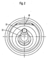
- the support sleeve 20 is also substantially cylindrical, except that it has on its outer periphery, for example, an inwardly staggered flat portion 46, which is best based on Fig.2 you can see.
- This flat portion 46 cooperates with the bead 18 of the receiving socket 6 as a rotation, when the support sleeve 20 is inserted into the receiving socket 6 by an axial linear movement in the direction of the arrow 48, which parallel to the central axes 38, 50 of the support sleeve 20 and the receiving socket 6 is.
- the flat portion 46 slides axially along the bead 18, whereby early rotation of the support sleeve 20 is prevented relative to the receiving socket 6.
- the carrier bush 20 is also guided by its remaining circumference in the receiving socket 6 until its collar 42 abuts against the bead 16 of the receiving socket 6.
- This stop is preferably secured by a collar 42 and the bead 16 radially encompassing positive locking means, preferably by a clamping strap 52, which is placed after insertion of the carrier sleeve 20 in the receiving socket 6 and tightened.
- a clamping strap 52 which is placed after insertion of the carrier sleeve 20 in the receiving socket 6 and tightened.
- the already rotatable carrier bush 20 also held axially fixed in the receiving socket 6.
- the angle of the collar and the end face 44 of the bead 16 provides wedge action.
Landscapes
- Engineering & Computer Science (AREA)
- General Engineering & Computer Science (AREA)
- Chemical & Material Sciences (AREA)
- Mechanical Engineering (AREA)
- Analytical Chemistry (AREA)
- Combustion & Propulsion (AREA)
- Physics & Mathematics (AREA)
- General Physics & Mathematics (AREA)
- Exhaust Silencers (AREA)
- Exhaust Gas After Treatment (AREA)
- Cylinder Crankcases Of Internal Combustion Engines (AREA)
- Characterised By The Charging Evacuation (AREA)
Priority Applications (1)
| Application Number | Priority Date | Filing Date | Title |
|---|---|---|---|
| PL07014733T PL1905973T3 (pl) | 2006-09-20 | 2007-07-27 | Obudowa lub rura prowadząca spaliny układu wydechowego silnika spalinowego |
Applications Claiming Priority (1)
| Application Number | Priority Date | Filing Date | Title |
|---|---|---|---|
| DE102006044736A DE102006044736B4 (de) | 2006-09-20 | 2006-09-20 | Abgasführendes Gehäuse oder Rohr einer Abgasanlage einer Brennkraftmaschine |
Publications (2)
| Publication Number | Publication Date |
|---|---|
| EP1905973A1 EP1905973A1 (de) | 2008-04-02 |
| EP1905973B1 true EP1905973B1 (de) | 2009-02-18 |
Family
ID=38664401
Family Applications (1)
| Application Number | Title | Priority Date | Filing Date |
|---|---|---|---|
| EP07014733A Active EP1905973B1 (de) | 2006-09-20 | 2007-07-27 | Abgasführendes Gehäuse oder Rohr einer Abgasanlage einer Brennkraftmaschine |
Country Status (5)
| Country | Link |
|---|---|
| EP (1) | EP1905973B1 (pl) |
| AT (1) | ATE423270T1 (pl) |
| DE (2) | DE102006044736B4 (pl) |
| DK (1) | DK1905973T3 (pl) |
| PL (1) | PL1905973T3 (pl) |
Families Citing this family (3)
| Publication number | Priority date | Publication date | Assignee | Title |
|---|---|---|---|---|
| DE102013103808B4 (de) | 2013-04-16 | 2021-09-02 | Tenneco Gmbh | Montagestutzen für Abgasrohr |
| DE102014110849A1 (de) * | 2014-07-31 | 2016-02-04 | Friedrich Boysen Gmbh & Co. Kg | Klappeneinrichtung |
| DE102019104770A1 (de) | 2019-02-26 | 2020-08-27 | Eberspächer Exhaust Technology GmbH & Co. KG | Sondenträgeranordnung |
Family Cites Families (8)
| Publication number | Priority date | Publication date | Assignee | Title |
|---|---|---|---|---|
| DE4224251C1 (de) * | 1992-07-22 | 1993-12-02 | Zeuna Staerker Kg | Rohr- oder Schalenelement einer Abgasleitung mit einem Sondenstutzen |
| DE19532330A1 (de) * | 1995-09-01 | 1997-03-06 | Teves Gmbh Alfred | Sensor-Haltebaugruppe, insbesondere für Drehzahlsensoren |
| JP2001305097A (ja) * | 2000-04-24 | 2001-10-31 | Ngk Spark Plug Co Ltd | ガスセンサ |
| DE10203310A1 (de) * | 2002-01-29 | 2003-07-31 | Daimler Chrysler Ag | Probenahmesystem für Abgassensoren |
| DE10210313B4 (de) * | 2002-03-08 | 2004-07-08 | Robert Bosch Gmbh | Meßfühleranordnung |
| DE10346205B4 (de) | 2003-02-26 | 2008-03-06 | Robert Bosch Gmbh | Vorrichtung zur Befestigung eines Messfühlers |
| CA2562898A1 (en) * | 2004-05-12 | 2005-11-17 | Reinz-Dichtungs-Gmbh | Fitting device |
| DE102005001453A1 (de) * | 2005-01-12 | 2006-07-20 | Reinz-Dichtungs-Gmbh | Halterungsvorrichtung |
-
2006
- 2006-09-20 DE DE102006044736A patent/DE102006044736B4/de active Active
-
2007
- 2007-07-27 DK DK07014733T patent/DK1905973T3/da active
- 2007-07-27 DE DE502007000447T patent/DE502007000447D1/de active Active
- 2007-07-27 AT AT07014733T patent/ATE423270T1/de active
- 2007-07-27 PL PL07014733T patent/PL1905973T3/pl unknown
- 2007-07-27 EP EP07014733A patent/EP1905973B1/de active Active
Also Published As
| Publication number | Publication date |
|---|---|
| DE102006044736A1 (de) | 2008-03-27 |
| ATE423270T1 (de) | 2009-03-15 |
| EP1905973A1 (de) | 2008-04-02 |
| DK1905973T3 (da) | 2009-05-11 |
| DE502007000447D1 (de) | 2009-04-02 |
| PL1905973T3 (pl) | 2009-07-31 |
| DE102006044736B4 (de) | 2008-07-24 |
Similar Documents
| Publication | Publication Date | Title |
|---|---|---|
| EP2426315B1 (de) | Rotorabschnitt für einen Rotor einer Turbomaschine | |
| DE69814928T2 (de) | Entkuppler für abgassysteme | |
| EP2980379B1 (de) | Injektionseinrichtung und zugehöriges herstellungsverfahren | |
| DE102013103970B4 (de) | Magnetisch-induktives Durchflussmessgerät insbesondere für Hochdruckanwendungen | |
| EP2646270B1 (de) | Einsatz für einen einfüllstutzen eines harnstoffbehälters | |
| WO2002021005A1 (de) | Umlenkrolle für einen zugmitteltrieb | |
| EP1905973B1 (de) | Abgasführendes Gehäuse oder Rohr einer Abgasanlage einer Brennkraftmaschine | |
| DE4307514A1 (pl) | ||
| DE4030486A1 (de) | Verbindungsausfuehrung fuer abzweigverbinder in einer hochdruck-kraftstoffschiene | |
| EP3702594B1 (de) | Sondenträgeranordnung | |
| DE19503346C2 (de) | Rohrbauteil | |
| EP2270320B1 (de) | Sondenstutzen und Verfahren zu dessen Herstellung | |
| DD297499A5 (de) | Befestigung und befestigungsverfahren | |
| DE102014011606B4 (de) | Abgassystem für eine Brennkraftmaschine | |
| DE3822944C2 (pl) | ||
| DE102009016688A1 (de) | Hülsenelement zur axialen Festlegung sowie Abgasturbolader | |
| DE2436112A1 (de) | Flanschverbindung fuer rohrleitungen | |
| EP3143274B1 (de) | Kraftstoffzuleitungseinrichtung an einem kraftstoffinjektor und kraftstoffinjektor | |
| EP1767752B1 (de) | Abgasbehandlungseinrichtung | |
| AT402656B (de) | Hydraulischer arbeitszylinder hydraulischer arbeitszylinder | |
| DE102010031656A1 (de) | Vorrichtung zum Einbau eines Messfühlers | |
| DE102008050073A1 (de) | Anschluss für ein Rohr | |
| EP0686798B1 (de) | Steckkupplung | |
| DE202010016196U1 (de) | Verdrehsicherung | |
| DE102011055447A1 (de) | Feststofftransportrohr |
Legal Events
| Date | Code | Title | Description |
|---|---|---|---|
| PUAI | Public reference made under article 153(3) epc to a published international application that has entered the european phase |
Free format text: ORIGINAL CODE: 0009012 |
|
| 17P | Request for examination filed |
Effective date: 20070728 |
|
| AK | Designated contracting states |
Kind code of ref document: A1 Designated state(s): AT BE BG CH CY CZ DE DK EE ES FI FR GB GR HU IE IS IT LI LT LU LV MC MT NL PL PT RO SE SI SK TR |
|
| AX | Request for extension of the european patent |
Extension state: AL BA HR MK YU |
|
| GRAP | Despatch of communication of intention to grant a patent |
Free format text: ORIGINAL CODE: EPIDOSNIGR1 |
|
| AKX | Designation fees paid |
Designated state(s): AT BE BG CH CY CZ DE DK EE ES FI FR GB GR HU IE IS IT LI LT LU LV MC MT NL PL PT RO SE SI SK TR |
|
| GRAS | Grant fee paid |
Free format text: ORIGINAL CODE: EPIDOSNIGR3 |
|
| GRAA | (expected) grant |
Free format text: ORIGINAL CODE: 0009210 |
|
| AK | Designated contracting states |
Kind code of ref document: B1 Designated state(s): AT BE BG CH CY CZ DE DK EE ES FI FR GB GR HU IE IS IT LI LT LU LV MC MT NL PL PT RO SE SI SK TR |
|
| REG | Reference to a national code |
Ref country code: GB Ref legal event code: FG4D Free format text: NOT ENGLISH |
|
| REG | Reference to a national code |
Ref country code: CH Ref legal event code: EP |
|
| REG | Reference to a national code |
Ref country code: IE Ref legal event code: FG4D Free format text: LANGUAGE OF EP DOCUMENT: GERMAN |
|
| REF | Corresponds to: |
Ref document number: 502007000447 Country of ref document: DE Date of ref document: 20090402 Kind code of ref document: P |
|
| REG | Reference to a national code |
Ref country code: CH Ref legal event code: NV Representative=s name: ISLER & PEDRAZZINI AG |
|
| REG | Reference to a national code |
Ref country code: DK Ref legal event code: T3 |
|
| REG | Reference to a national code |
Ref country code: SE Ref legal event code: TRGR |
|
| PG25 | Lapsed in a contracting state [announced via postgrant information from national office to epo] |
Ref country code: SI Free format text: LAPSE BECAUSE OF FAILURE TO SUBMIT A TRANSLATION OF THE DESCRIPTION OR TO PAY THE FEE WITHIN THE PRESCRIBED TIME-LIMIT Effective date: 20090218 Ref country code: LT Free format text: LAPSE BECAUSE OF FAILURE TO SUBMIT A TRANSLATION OF THE DESCRIPTION OR TO PAY THE FEE WITHIN THE PRESCRIBED TIME-LIMIT Effective date: 20090218 Ref country code: FI Free format text: LAPSE BECAUSE OF FAILURE TO SUBMIT A TRANSLATION OF THE DESCRIPTION OR TO PAY THE FEE WITHIN THE PRESCRIBED TIME-LIMIT Effective date: 20090218 Ref country code: ES Free format text: LAPSE BECAUSE OF FAILURE TO SUBMIT A TRANSLATION OF THE DESCRIPTION OR TO PAY THE FEE WITHIN THE PRESCRIBED TIME-LIMIT Effective date: 20090529 |
|
| REG | Reference to a national code |
Ref country code: PL Ref legal event code: T3 |
|
| PG25 | Lapsed in a contracting state [announced via postgrant information from national office to epo] |
Ref country code: LV Free format text: LAPSE BECAUSE OF FAILURE TO SUBMIT A TRANSLATION OF THE DESCRIPTION OR TO PAY THE FEE WITHIN THE PRESCRIBED TIME-LIMIT Effective date: 20090218 Ref country code: IS Free format text: LAPSE BECAUSE OF FAILURE TO SUBMIT A TRANSLATION OF THE DESCRIPTION OR TO PAY THE FEE WITHIN THE PRESCRIBED TIME-LIMIT Effective date: 20090618 |
|
| REG | Reference to a national code |
Ref country code: IE Ref legal event code: FD4D |
|
| PG25 | Lapsed in a contracting state [announced via postgrant information from national office to epo] |
Ref country code: PT Free format text: LAPSE BECAUSE OF FAILURE TO SUBMIT A TRANSLATION OF THE DESCRIPTION OR TO PAY THE FEE WITHIN THE PRESCRIBED TIME-LIMIT Effective date: 20090727 Ref country code: IE Free format text: LAPSE BECAUSE OF FAILURE TO SUBMIT A TRANSLATION OF THE DESCRIPTION OR TO PAY THE FEE WITHIN THE PRESCRIBED TIME-LIMIT Effective date: 20090218 Ref country code: EE Free format text: LAPSE BECAUSE OF FAILURE TO SUBMIT A TRANSLATION OF THE DESCRIPTION OR TO PAY THE FEE WITHIN THE PRESCRIBED TIME-LIMIT Effective date: 20090218 Ref country code: CZ Free format text: LAPSE BECAUSE OF FAILURE TO SUBMIT A TRANSLATION OF THE DESCRIPTION OR TO PAY THE FEE WITHIN THE PRESCRIBED TIME-LIMIT Effective date: 20090218 |
|
| PG25 | Lapsed in a contracting state [announced via postgrant information from national office to epo] |
Ref country code: SK Free format text: LAPSE BECAUSE OF FAILURE TO SUBMIT A TRANSLATION OF THE DESCRIPTION OR TO PAY THE FEE WITHIN THE PRESCRIBED TIME-LIMIT Effective date: 20090218 Ref country code: RO Free format text: LAPSE BECAUSE OF FAILURE TO SUBMIT A TRANSLATION OF THE DESCRIPTION OR TO PAY THE FEE WITHIN THE PRESCRIBED TIME-LIMIT Effective date: 20090218 |
|
| PLBE | No opposition filed within time limit |
Free format text: ORIGINAL CODE: 0009261 |
|
| STAA | Information on the status of an ep patent application or granted ep patent |
Free format text: STATUS: NO OPPOSITION FILED WITHIN TIME LIMIT |
|
| 26N | No opposition filed |
Effective date: 20091119 |
|
| PG25 | Lapsed in a contracting state [announced via postgrant information from national office to epo] |
Ref country code: BG Free format text: LAPSE BECAUSE OF FAILURE TO SUBMIT A TRANSLATION OF THE DESCRIPTION OR TO PAY THE FEE WITHIN THE PRESCRIBED TIME-LIMIT Effective date: 20090518 |
|
| BERE | Be: lapsed |
Owner name: ROTH-TECHNIK AUSTRIA -G. M.B.H. Effective date: 20090731 |
|
| PG25 | Lapsed in a contracting state [announced via postgrant information from national office to epo] |
Ref country code: MC Free format text: LAPSE BECAUSE OF NON-PAYMENT OF DUE FEES Effective date: 20090731 |
|
| PG25 | Lapsed in a contracting state [announced via postgrant information from national office to epo] |
Ref country code: BE Free format text: LAPSE BECAUSE OF NON-PAYMENT OF DUE FEES Effective date: 20090731 |
|
| PG25 | Lapsed in a contracting state [announced via postgrant information from national office to epo] |
Ref country code: GR Free format text: LAPSE BECAUSE OF FAILURE TO SUBMIT A TRANSLATION OF THE DESCRIPTION OR TO PAY THE FEE WITHIN THE PRESCRIBED TIME-LIMIT Effective date: 20090519 |
|
| PG25 | Lapsed in a contracting state [announced via postgrant information from national office to epo] |
Ref country code: LU Free format text: LAPSE BECAUSE OF NON-PAYMENT OF DUE FEES Effective date: 20090727 |
|
| PG25 | Lapsed in a contracting state [announced via postgrant information from national office to epo] |
Ref country code: HU Free format text: LAPSE BECAUSE OF FAILURE TO SUBMIT A TRANSLATION OF THE DESCRIPTION OR TO PAY THE FEE WITHIN THE PRESCRIBED TIME-LIMIT Effective date: 20090819 |
|
| PG25 | Lapsed in a contracting state [announced via postgrant information from national office to epo] |
Ref country code: TR Free format text: LAPSE BECAUSE OF FAILURE TO SUBMIT A TRANSLATION OF THE DESCRIPTION OR TO PAY THE FEE WITHIN THE PRESCRIBED TIME-LIMIT Effective date: 20090218 |
|
| PG25 | Lapsed in a contracting state [announced via postgrant information from national office to epo] |
Ref country code: CY Free format text: LAPSE BECAUSE OF FAILURE TO SUBMIT A TRANSLATION OF THE DESCRIPTION OR TO PAY THE FEE WITHIN THE PRESCRIBED TIME-LIMIT Effective date: 20090218 |
|
| REG | Reference to a national code |
Ref country code: FR Ref legal event code: PLFP Year of fee payment: 10 |
|
| REG | Reference to a national code |
Ref country code: FR Ref legal event code: PLFP Year of fee payment: 11 |
|
| REG | Reference to a national code |
Ref country code: FR Ref legal event code: PLFP Year of fee payment: 12 |
|
| PGFP | Annual fee paid to national office [announced via postgrant information from national office to epo] |
Ref country code: NL Payment date: 20250723 Year of fee payment: 19 |
|
| PGFP | Annual fee paid to national office [announced via postgrant information from national office to epo] |
Ref country code: DE Payment date: 20250528 Year of fee payment: 19 Ref country code: DK Payment date: 20250723 Year of fee payment: 19 |
|
| PGFP | Annual fee paid to national office [announced via postgrant information from national office to epo] |
Ref country code: PL Payment date: 20250710 Year of fee payment: 19 Ref country code: IT Payment date: 20250731 Year of fee payment: 19 |
|
| PGFP | Annual fee paid to national office [announced via postgrant information from national office to epo] |
Ref country code: GB Payment date: 20250724 Year of fee payment: 19 |
|
| PGFP | Annual fee paid to national office [announced via postgrant information from national office to epo] |
Ref country code: FR Payment date: 20250723 Year of fee payment: 19 Ref country code: AT Payment date: 20250721 Year of fee payment: 19 |
|
| PGFP | Annual fee paid to national office [announced via postgrant information from national office to epo] |
Ref country code: CH Payment date: 20250801 Year of fee payment: 19 Ref country code: SE Payment date: 20250723 Year of fee payment: 19 |