EP1905673A2 - Fahrantrieb insbesondere eines Universalfahrzeuges für Unterstützungssysteme - Google Patents
Fahrantrieb insbesondere eines Universalfahrzeuges für Unterstützungssysteme Download PDFInfo
- Publication number
- EP1905673A2 EP1905673A2 EP07017819A EP07017819A EP1905673A2 EP 1905673 A2 EP1905673 A2 EP 1905673A2 EP 07017819 A EP07017819 A EP 07017819A EP 07017819 A EP07017819 A EP 07017819A EP 1905673 A2 EP1905673 A2 EP 1905673A2
- Authority
- EP
- European Patent Office
- Prior art keywords
- vehicle
- turntable
- steering
- drive
- drive according
- Prior art date
- Legal status (The legal status is an assumption and is not a legal conclusion. Google has not performed a legal analysis and makes no representation as to the accuracy of the status listed.)
- Granted
Links
- 239000002828 fuel tank Substances 0.000 claims abstract description 5
- 230000005540 biological transmission Effects 0.000 claims description 5
- 239000000725 suspension Substances 0.000 claims description 5
- 230000008901 benefit Effects 0.000 description 3
- 238000005452 bending Methods 0.000 description 2
- 238000010276 construction Methods 0.000 description 2
- 230000010354 integration Effects 0.000 description 2
- 238000000926 separation method Methods 0.000 description 2
- 230000006978 adaptation Effects 0.000 description 1
- 230000008030 elimination Effects 0.000 description 1
- 238000003379 elimination reaction Methods 0.000 description 1
- 239000002689 soil Substances 0.000 description 1
Images

Classifications
-
- B—PERFORMING OPERATIONS; TRANSPORTING
- B62—LAND VEHICLES FOR TRAVELLING OTHERWISE THAN ON RAILS
- B62D—MOTOR VEHICLES; TRAILERS
- B62D11/00—Steering non-deflectable wheels; Steering endless tracks or the like
- B62D11/20—Endless-track steering having pivoted bogie carrying track
Definitions
- the invention relates to a travel drive of a vehicle, in particular for a universal vehicle for support systems.
- Tracked vehicles however, have the great disadvantage that only a slight flexibility of movement of the vehicle is given due to the large chains.
- the associated space for these crawler tracks is also very high.
- the off-road vehicle Bv 206 of this company is separated into a front vehicle and a rear vehicle with both sides of the front and on the rear vehicle mounted circulating chains. Both vehicle parts are connected to each other by means of articulated steering. The drive of the front vehicle acts on the chains of the rear vehicle.
- From the DE 101 00 775 A1 is also known a articulated vehicle. This has two in the vehicle longitudinal direction one behind the other chassis parts on which on the one hand a front axle and on the other hand a rear axle are attached.
- the chassis parts are available via a substantially vertically aligned bending axis in such a way that they can be pivoted against each other using a control device and thus allow a vehicle steering.
- the invention therefore has the task of making vehicles with crawler tracks maneuverable and thus to show a tracked vehicle with improved properties.
- the invention is based on the idea to design a vehicle with several smaller crawler tracks on the vehicle and thereby achieve a very high mobility of the vehicle.
- Multi-track drives as such are known from the so-called “Mattracks” ago and represent a retrofit version for wheeled vehicles. They are each attached to the existing axles.
- a steered and spring-loaded rubber crawler drive for such multi-chain drives for example, with the DE 200 00 737 U1 disclosed.
- the rubber crawler here is a treadmill carriage and two upper support rollers out, so that the treadmill carriage is resiliently mounted to the machine frame via a rocker and one or more spring elements.
- the newly designed multi-chain drives have properties of a fifth wheel and in continuation of an articulated steering.
- the conventional fifth wheel steering is mainly used in the field of trailer, handcart and horse carts. It is a steering system with a stool-like carrier for axle and wheels and is mounted on a rotatably mounted pin.
- articulated steering the steering is known not by deflection of individual wheels, but by bending a joint in the vehicle frame. This type of steering is often seen in self-propelled construction and machinery, where it depends on a good maneuverability.
- a so-called articulated handlebar is published on the website http://www.stbg.de/Zeitung/se602/bell.htm .
- the multi-chain drives preferably a plurality of so-called fifth wheel units are connected via a kind of turntable with the actual vehicle chassis.
- the suspension of the fifth wheel units to the vehicle for example, by means of hydropneumatic turntable - springs.
- the proposed fifth wheel unit also comprises at least one right and one left mounted chain drive.
- the two-sided drives in turn have struts.
- the pairwise drives are preferably driven by a common drive.
- This drive is preferably located in each of the fifth wheel units and may be a conventional engine, such as a 10-cylinder TDI engine, which is connected to a transmission with differential. About this, the drive is transmitted to the tracks in a known manner.
- the integration of a fuel tank in / on the turntable unit is also envisaged.
- the front and rear fifth wheel unit and thus the drives are preferably steered or rotated via steering cylinder.
- the steering cylinder are connected on one side with the turntable unit and the vehicle.
- the combination of both systems in the multi-chain drives has the advantage that a faster off-road than in normal tracked vehicles is achieved.
- the articulated steering eliminates the known disadvantages of differential speed steering.
- the mobility of the fifth wheel around the longitudinal axis prevents overloading of the individual chains.
- the mobility of the fifth wheel around the transverse axis allows a very good adaptation of the vehicle to the respective terrain contour. With locked turntables also a very good trench crossing capability of the vehicle is guaranteed.
- the tilting of the turntable also allows very good angle of repose. It is also possible to break loose from heavy soil by buckling.
- An even number of chain drives such as four, six, eight, etc. combine the benefits of wheel and track drives.
- FIG. 1 shows a chassis 1 of a turntable unit 10 for receiving a drive 2 shown in more detail in FIG. 2, a transmission 3 and an indicated fuel tank 4.
- Push rods 5 are connected to the chassis 1 and a turntable 6 (to be described).
- hydropneumatic fifth wheel suspension 7 integrated. 8 with a right and left attached to the chassis 1 chain drive with struts are marked as pairs of tracks.
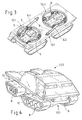
- Fig. 3 at least two steering cylinders 9 are shown, wherein the steering cylinder 9.1 on the one hand with the front fifth wheel unit 10.1 and the chassis 1 and the second steering cylinder 9.2 with a vehicle lower part 1001 of a vehicle 100 shown in FIG. 4 and the rear fifth wheel unit 10.2 are connected.
- the steering cylinder 9 are connected in normal drive manner with a steering (not shown in detail) of the vehicle 100 that at a right steering angle of the steering cylinder 9.1, the front fifth wheel unit 10.1 and the second steering cylinder 9.2 pull the rear fifth wheel unit 10.2 respectively to the right or left Steering accordingly to the left.
- the rotation of the turntable units 10 is made possible by the respective turntable 6.
- the push rods 5 support the steering cylinder 9.
- the vehicle 100 thus reacts like a normally steered wheeled vehicle, the pairs of tracks 8 are adjusted symmetrically with each other.
- the pairs of tracks 8 are thereby asymmetrically adjusted to each other as in a larger construction vehicle. This then allows for sideways driving or driving in a circle etc.
- the hydropneumatic fifth wheel suspensions 7 in the fifth wheel units 10 have the primary task of absorbing impacts and are used for decoupling the vehicle 100th
Landscapes
- Engineering & Computer Science (AREA)
- Combustion & Propulsion (AREA)
- Transportation (AREA)
- Mechanical Engineering (AREA)
- Chemical & Material Sciences (AREA)
- Vehicle Body Suspensions (AREA)
- Steering-Linkage Mechanisms And Four-Wheel Steering (AREA)
- Heat Treatment Of Articles (AREA)
- Non-Deflectable Wheels, Steering Of Trailers, Or Other Steering (AREA)
- Harvester Elements (AREA)
- Automatic Cycles, And Cycles In General (AREA)
- Cooling, Air Intake And Gas Exhaust, And Fuel Tank Arrangements In Propulsion Units (AREA)
- Arrangement Or Mounting Of Propulsion Units For Vehicles (AREA)
Abstract
Description
- Die Erfindung betrifft einen Fahrantrieb eines Fahrzeuges insbesondere für ein Universalfahrzeug für Unterstützungssysteme.
- Bekannt sind Gefechtsfahrzeuge, gepanzerte oder ungepanzerte, die eine hohe Modularität aufweisen, um den unterschiedlichsten Anforderungen der heutigen Zeit an militärische Fahrzeuge zu entsprechen. Diese können Rad- oder Kettenlaufwerke besitzen (
DE 101 33 147 B4 ,DE 10 2004 006 152 A1 ). - Kettenfahrzeuge haben jedoch den großen Nachteil, dass nur eine geringe Bewegungsflexibilität des Fahrzeuges bedingt durch die großen Ketten gegeben ist. Der damit verbundene Bauraum für diese Kettenlaufwerke ist zudem sehr hoch.
- Insbesondere für leichte Fahrzeuge sind derartige Kettenlaufwerke daher oft unerwünscht.
- Um auch größere Fahrzeuge manövrierbarer zu gestalten, werden in der Praxis diese Fahrzeuge unterteilt, so bekannt von der Firma Hägglund. Das Geländetransportfahrzeug Bv 206 dieser Firma ist getrennt in ein Vorderfahrzeug und ein Hinterfahrzeug mit beidseitig am Vorder- als auch am Hinterfahrzeug angebrachten umlaufenden Ketten. Beide Fahrzeugteile sind mittels einer Knicklenkung miteinander verbunden. Der Antrieb des Vorderfahrzeuges wirkt dabei auch auf die Ketten des Hinterfahrzeuges.
- Aus der
DE 101 00 775 A1 ist gleichfalls ein knickgelenktes Fahrzeug bekannt. Dieses weist zwei in Fahrzeuglängsrichtung hintereinander liegende Chassisteile auf, an denen einerseits eine Vorderachse und andererseits eine Hinterachse befestigt sind. Die Chassisteile stehen über eine im Wesentlichen vertikal ausgerichteten Knickachse derart miteinander in Verbindung, dass sie sich unter Verwendung einer Steuereinrichtung gegeneinander verschwenken lassen und somit eine Fahrzeuglenkung ermöglichen. - Zwar ist dieser Gesamtzug wesentlich beweglicher als beispielsweise ein herkömmlicher Pionierpanzer, jedoch ist eine Trennung des Fahrzeuges in ein Hauptfahrzeug und einen Anhänger in der Praxis unerwünscht.
- Hier stellt sich die Erfindung daher die Aufgabe, Fahrzeuge mit Kettenlaufwerken manövrierfähiger zu machen und somit ein Kettenfahrzeug mit verbesserten Eigenschaften aufzuzeigen.
- Gelöst wird die Aufgabe durch die Merkmale des Patentanspruchs 1. Vorteilhafte Ausführungen sind in den Unteransprüchen aufgeführt.
- Der Erfindung liegt die Idee zugrunde, ein Fahrzeug mit mehreren kleineren Kettenlaufwerken am Fahrzeug zu konzipieren und dadurch eine sehr hohe Beweglichkeit des Fahrzeuges zu erreichen.
- Mehrkettenlaufwerke als solche sind von den so genannten "Mattracks" her bekannt und stellen eine Nachrüstvariante für Radfahrzeuge dar. Sie werden jeweils an den vorhandenen Radachsen angebracht.
- Ein gelenktes und gefedertes Gummiraupenbandlaufwerk für derartige Mehrketten-Laufwerke wird beispielsweise mit der
DE 200 00 737 U1 offenbart. Das Gummiraupenlaufband ist hierbei um einen Laufbandwagen und zwei obere Tragrollen geführt, so dass der Laufbandwagen zum Maschinenrahmen hin über eine Schwinge und ein oder mehreren Federelementen federnd gelagert ist. - Die neu konzipierten Mehrketten-Laufwerke hingegen weisen Eigenschaften eines Drehschemels und in Weiterführung eines Knicklenkers auf.
- Die herkömmliche Drehschemellenkung findet vor allem im Bereich von Anhängerwagen, Handkarren und Pferdefuhrwerken Verwendung. Sie ist ein Lenksystem mit einem schemelartigen Träger für Achse und Räder und steckt auf einem drehbar gelagerten Zapfen.
- Bei Knicklenkern erfolgt die Lenkung bekanntlich nicht durch Auslenkung einzelner Räder, sondern durch Knicken eines Gelenkes im Fahrzeugrahmen. Diese Art von Lenkung sieht man häufig bei selbst fahrenden Bau- und Arbeitsmaschinen, bei denen es auf eine gute Wendigkeit ankommt. Ein so genannter Knicklenker wird auf der Internetseite http://www.stbg.de/Zeitung/se602/bell.htm publiziert.
- Bei der Konzipierung der Mehrketten-Laufwerke ist vorgesehen, dass bevorzugt mehrere so genannte Drehschemeleinheiten über eine Art Drehkranz mit dem eigentlichen Fahrzeugchassis verbunden sind. Die Abfederung der Drehschemeleinheiten zum Fahrzeug erfolgt beispielsweise mittels hydropneumatischer Drehschemel - Federn.
- Die vorgeschlagene Drehschemeleinheit umfasst zudem wenigstens ein rechts und ein links angebrachtes Kettenlaufwerk. Die beidseitigen Laufwerke weisen ihrerseits Federbeine auf. Die Paarweisen Laufwerke werden vorzugsweise durch einen gemeinsamen Antrieb angetrieben. Dieser Antrieb befindet sich dabei bevorzugt in jeder der Drehschemeleinheiten und kann dabei ein herkömmlicher Motor sein, beispielsweise ein 10 Zylinder TDI Motor, welcher mit einem Getriebe mit Differential verbunden ist. Über dieses wird der Antrieb auf die Laufketten in bekannter Art und Weise übertragen. Vorgesehen ist auch die Einbindung eines Kraftstofftanks in / an die Drehschemeleinheit.
- Die vordere und hintere Drehschemeleinheit und damit die Laufwerke werden vorzugsweise über Lenkzylinder gelenkt bzw. verdreht. Dazu sind die Lenkzylinder einseitig mit der Drehschemeleinheit und dem Fahrzeug verbunden.
- Die Kombination beider Systeme in den Mehrketten-Laufwerken hat den Vorteil, dass eine schnellere Geländefahrt als bei normalen Kettenfahrzeugen erreicht wird. Die Knicklenkung eliminiert die bekannten Nachteile einer Differenzdrehzahllenkung. Die Beweglichkeit der Drehschemel um die Längsachse verhindert eine Überlastung der einzelnen Ketten. Die Beweglichkeit der Drehschemel um die Querachse erlaubt eine sehr gute Anpassung des Fahrzeugs an die jeweilige Geländekontur. Bei verriegelten Drehschemeln wird zudem eine sehr gute Grabenüberschreitfähigkeit des Fahrzeugs garantiert. Das Ankippen der Drehschemel ermöglicht des Weiteren sehr gute Böschungswinkel. Auch ist das Losbrechen aus schwerem Boden mittels Einknicken machbar.
- Weitere Vorteile sind eine geringere Bauhöhe als bei großen Einzel-Laufwerken, das Entfallen des teueren Überlagerungs-Lenkantriebes sowie das Absenken des Fahrzeugs ohne Einschränkung der Bodenfreiheit. Mit den neuartigen Mehrketten-Laufwerken ist auch das seitwärts Fahren unproblematisch. Das seitliche "Ausstrecken" der Laufwerke durch asymmetrischen Drehpunkt erhöht zudem die Standsicherheit bei Bagger- und Kranarbeiten. Die Mehrketten-Laufwerke ermöglichen auch eine gute Entkopplung zur Fahrzeugwanne, wodurch weniger Vibration eingeleitet wird. Ein ungefedertes Aufsetzen des Leitrades beim Durchfedern der Laufrollen ist ausgeschlossen. Ein weiterer positiver Aspekt ist der einfache Kettenwechsel. Dies kann durch selbstständiges Anheben einer Laufwerk-Seite erfolgen. Auch wird dadurch der Schutz der Besatzung gegen Minen erhöht.
- Durch eine geradzahlige Anzahl von Ketten-Laufwerken, wie vier, sechs, acht etc., werden insbesondere die Vorteile von Rad- und Kettenlaufwerken vereint.
- Anhand eines Ausführungsbeispiels mit Zeichnung soll die Erfindung näher erläutert werden.
- Es zeigt:
- Fig. 1
- eine Drehschemeleinheit im Rohbau,
- Fig. 2
- die Drehschemeleinheit aus Fig. 1 mit zwei Laufwerken, Antrieb, Getriebe und Kraftstofftank,
- Fig. 3
- die Einbindung beider Drehschemeleinheiten in einen Fahrzeugunterbau,
- Fig. 4
- ein Vier-Laufwerk-Fahrzeug mit der erfindungsgemäßen Drehschemel- und Knicklenkung.
- In Fig. 1 dargestellt ist ein Chassis 1 einer Drehschemeleinheit 10 zur Aufnahme eines in Fig. 2 näher dargestellten Antriebes 2, eines Getriebes 3 sowie eines angedeuteten Kraftstoffbehälters 4. Schubstützen 5 sind mit dem Chassis 1 und einem Drehkranz 6 verbunden (wird noch ausgeführt). Zwischen Drehkranz 6 und dem Chassis 1 sind zudem, in diesem konkreten Ausführungsbeispiel bevorzugt, hydropneumatische Drehschemel-Federungen 7 eingebunden. Mit 8 sind ein rechts und links am Chassis 1 angebrachtes Kettenlaufwerk mit Federbeinen als Laufkettenpaare gekennzeichnet.
- In Fig. 3 sind wenigstens zwei Lenkzylinder 9 dargestellt, wobei der Lenkzylinder 9.1 einerseits mit der vorderen Drehschemeleinheit 10.1 und dem Chassis 1 und der zweite Lenkzylinder 9.2 mit eine Fahrzeugunterteil 1001 eines in Fig. 4 dargestellten Fahrzeuges 100 und der hinteren Drehschemeleinheit 10.2 verbunden sind.
- Die Lenkzylinder 9 sind in normaler Antriebsart derart mit einer Lenkung (nicht näher dargestellt) des Fahrzeuges 100 verbunden, dass bei einem rechten Lenkeinschlag der Lenkzylinder 9.1 die vordere Drehschemeleinheit 10.1 und der zweite Lenkzylinder 9.2 die hintere Drehschemeleinheit 10.2 jeweils nach rechts ziehen oder bei einem linken Lenkeinschlag entsprechend nach links. Das Verdrehen der Drehschemeleinheiten 10 wird durch den jeweiligen Drehkranz 6 ermöglicht. Die Schubstützen 5 unterstützen die Lenkzylinder 9. Das Fahrzeug 100 reagiert somit wie ein normal gelenktes Radfahrzeug, die Laufkettenpaare 8 werden symmetrisch miteinander verstellt.
- Selbstverständlich ist bei entsprechender Trennung der beiden Lenkzylinder 9.1, 9.2 von der "normalen" Lenkung ein Verdrehen der Drehschemeleinheiten 10 unterhalb des Fahrzeuges 100 gegeneinander möglich. In diesem Fall würde der Lenkzylinder 9.1 die vordere Drehschemeleinheit 10.1 beispielsweise nach recht verdrehen, der zweite Lenkzylinder 9.2 die hintere Drehschemeleinheit 9.2 hingegen nach links oder umgekehrt. Die Laufkettenpaare 8 werden wie bei einem größeren Baufahrzeug dadurch asymmetrisch zueinander verstellt. Dies ermöglicht dann ein seitwärts Fahren oder ein Fahren im Kreis etc.
- Die hydropneumatische Drehschemel-Federungen 7 in den Drehschemeleinheiten 10 haben vorrangig die Aufgabe, Stoßeinwirkungen aufzufangen und dienen zur Entkopplung zum Fahrzeug 100.
Claims (9)
- Fahrantrieb für ein Fahrzeug (100), aufweisend mehrere Laufketten, dadurch gekennzeichnet, dass wenigsten zwei Drehschemeleinheiten (10) am Fahrzeug (100) vorgesehen ist, mit wenigstens jeweils zwei rechts und links angebrachten und ein Laufkettenpaar (8) bildenden Fahrantrieben, wobei die Drehschemeleinheiten (10) über jeweils einen Drehkranz (6) mit der Fahrzeug (100) verbunden und über diesen zum Fahrzeug (100) verdrehbar ist.
- Fahrantrieb nach Anspruch 1, dadurch gekennzeichnet, dass die Drehschemeleinheiten (10) über am Fahrzeug (100) befestigte und mit den Drehschemeleinheiten (10) verbundenen Lenkzylindern (9) verdreht werden, die ihrerseits mit einer fahrzeugseitigen Lenkung verbunden sind.
- Fahrantrieb nach Anspruch 1 oder 2, dadurch gekennzeichnet, dass eine symmetrische oder asymmetrische Lenkung möglich ist, wobei bei einer symmetrischen Auslenkung die Drehschemeleinheiten (10) in dieselbe Richtung ausgelenkt werden und bei einer asymmetrischen Auslenkung entgegen gesetzt.
- Fahrantrieb nach einem der Ansprüche 1 bis 3, dadurch gekennzeichnet, dass die Drehschemeleinheiten (10) zur Aufnahme eines elektrischen Antriebes (2), eines damit verbundenen Getriebes (3) sowie eines Kraftstoffbehälters (4) fungieren können.
- Fahrantrieb nach Anspruch 4, dadurch gekennzeichnet, dass wenigsten eine Drehschemeleinheit (10) einen elektrischen Antrieb (2) und das damit verbundene Getriebes (3) aufweist.
- Fahrantrieb nach einem der Ansprüche 1 bis 5, dadurch gekennzeichnet, dass Drehschemel-Federungen (7) in den Drehschemeleinheiten (10) eingebunden sind.
- Fahrantrieb nach Anspruch 6, dadurch gekennzeichnet, dass die Federungen (7) die zwischen dem Chassis (1) der Drehschemeleinheit (10) und dem Drehkranz (6) integriert sind.
- Fahrantrieb nach einem der Ansprüche 1 bis 7, dadurch gekennzeichnet, dass Schubstützen (5) in den Drehschemeleinheiten (10) die Lenkzylinder (9) unterstützen.
- Fahrantrieb nach einem der Ansprüche 1 bis 8, dadurch gekennzeichnet, dass ein selbstständiges Anheben einer Laufwerk-Seite möglich ist.
Priority Applications (1)
| Application Number | Priority Date | Filing Date | Title |
|---|---|---|---|
| PL07017819T PL1905673T3 (pl) | 2006-09-27 | 2007-09-12 | Napęd jezdny, zwłaszcza pojazdu uniwersalnego dla systemów wsparcia |
Applications Claiming Priority (1)
| Application Number | Priority Date | Filing Date | Title |
|---|---|---|---|
| DE102006045995A DE102006045995B4 (de) | 2006-09-27 | 2006-09-27 | Fahrantrieb insbesondere eines Universalfahrzeuges für Unterstützungssysteme |
Publications (3)
| Publication Number | Publication Date |
|---|---|
| EP1905673A2 true EP1905673A2 (de) | 2008-04-02 |
| EP1905673A3 EP1905673A3 (de) | 2009-04-08 |
| EP1905673B1 EP1905673B1 (de) | 2010-05-19 |
Family
ID=38779719
Family Applications (1)
| Application Number | Title | Priority Date | Filing Date |
|---|---|---|---|
| EP07017819A Not-in-force EP1905673B1 (de) | 2006-09-27 | 2007-09-12 | Fahrantrieb insbesondere eines Universalfahrzeuges für Unterstützungssysteme |
Country Status (5)
| Country | Link |
|---|---|
| EP (1) | EP1905673B1 (de) |
| AT (1) | ATE468262T1 (de) |
| DE (2) | DE102006045995B4 (de) |
| ES (1) | ES2345004T3 (de) |
| PL (1) | PL1905673T3 (de) |
Families Citing this family (1)
| Publication number | Priority date | Publication date | Assignee | Title |
|---|---|---|---|---|
| DE102015000412A1 (de) | 2015-01-14 | 2016-07-14 | Bundesrepublik Deutschland, vertreten durch das Bundesministerium der Verteidigung, vertreten durch das Bundesamt für Ausrüstung, Informationstechnik und Nutzung der Bundeswehr | Fahrzeugkonzept für leichte Kettenfahrzeuge |
Citations (4)
| Publication number | Priority date | Publication date | Assignee | Title |
|---|---|---|---|---|
| DE928864C (de) | 1942-02-20 | 1955-06-13 | Karl Gey | Fahrzeug mit Raupenfahrgestellen in Drehschemelanordnung |
| DE4005356A1 (de) | 1990-02-16 | 1991-08-22 | Noell Gmbh | Fahrzeug mit allradantrieb |
| DE29609176U1 (de) | 1996-05-22 | 1996-08-08 | Paul, Josef, 94474 Vilshofen | Fahrzeug, insbesondere Nutzfahrzeug |
| DE20000737U1 (de) | 2000-01-18 | 2000-04-06 | Rainer, Johann, Dipl.-Ing. (FH), 84177 Gottfrieding | Gelenktes und gefedertes Gummiraupenbandlaufwerk |
Family Cites Families (7)
| Publication number | Priority date | Publication date | Assignee | Title |
|---|---|---|---|---|
| DE3135908C2 (de) * | 1981-09-10 | 1992-02-06 | Hans Huttner-Fahrzeugbau, 8121 Raisting | Nachlauf-Anhänger |
| JPS616074A (ja) * | 1984-06-20 | 1986-01-11 | Matsushita Electric Ind Co Ltd | 自走式搬送車 |
| DE4005357A1 (de) * | 1990-02-16 | 1991-08-22 | Noell Gmbh | Fahrzeug mit mehreren bewegungsantrieben |
| DE19510893A1 (de) * | 1995-03-24 | 1996-09-26 | Herbert Mattle | Raupenfahrzeug als Kipplader mit mehrfacher Ladekapazität eines Radkippladers |
| DE10100775A1 (de) * | 2001-01-10 | 2002-07-11 | Deere & Co | Knickgelenktes Fahrzeug |
| DE10133147B4 (de) * | 2001-07-07 | 2004-02-12 | Rheinmetall Landsysteme Gmbh | Gepanzertes Transportfahrzeug |
| DE102004006152A1 (de) * | 2004-02-07 | 2005-09-08 | Rheinmetall Landsysteme Gmbh | Gepanzertes Kampffahrzeug |
-
2006
- 2006-09-27 DE DE102006045995A patent/DE102006045995B4/de not_active Expired - Fee Related
-
2007
- 2007-09-12 ES ES07017819T patent/ES2345004T3/es active Active
- 2007-09-12 AT AT07017819T patent/ATE468262T1/de active
- 2007-09-12 EP EP07017819A patent/EP1905673B1/de not_active Not-in-force
- 2007-09-12 PL PL07017819T patent/PL1905673T3/pl unknown
- 2007-09-12 DE DE502007003829T patent/DE502007003829D1/de active Active
Patent Citations (4)
| Publication number | Priority date | Publication date | Assignee | Title |
|---|---|---|---|---|
| DE928864C (de) | 1942-02-20 | 1955-06-13 | Karl Gey | Fahrzeug mit Raupenfahrgestellen in Drehschemelanordnung |
| DE4005356A1 (de) | 1990-02-16 | 1991-08-22 | Noell Gmbh | Fahrzeug mit allradantrieb |
| DE29609176U1 (de) | 1996-05-22 | 1996-08-08 | Paul, Josef, 94474 Vilshofen | Fahrzeug, insbesondere Nutzfahrzeug |
| DE20000737U1 (de) | 2000-01-18 | 2000-04-06 | Rainer, Johann, Dipl.-Ing. (FH), 84177 Gottfrieding | Gelenktes und gefedertes Gummiraupenbandlaufwerk |
Also Published As
| Publication number | Publication date |
|---|---|
| ATE468262T1 (de) | 2010-06-15 |
| EP1905673B1 (de) | 2010-05-19 |
| DE102006045995B4 (de) | 2009-02-12 |
| EP1905673A3 (de) | 2009-04-08 |
| PL1905673T3 (pl) | 2010-10-29 |
| ES2345004T3 (es) | 2010-09-13 |
| DE502007003829D1 (de) | 2010-07-01 |
| DE102006045995A1 (de) | 2008-04-03 |
Similar Documents
| Publication | Publication Date | Title |
|---|---|---|
| EP1172286B1 (de) | Fahrzeug mit um mehrere Achsen schwenbare Radgruppen oder Raupen | |
| EP2192026B2 (de) | Landwirtschaftliche Zugmaschine | |
| DE19506575C2 (de) | Aufhängungsvorrichtung für ein Raupenfahrzeug | |
| EP2627553B1 (de) | Antriebseinheit für ein transportsystem sowie transportsystem mit dieser antriebseinheit | |
| EP3075588B1 (de) | Fahrantrieb für ein elektrisch angetriebenes fahrzeug | |
| EP3569478A1 (de) | Landwirtschaftliches raupenfahrzeug | |
| EP2576327B1 (de) | Vorrichtung zur dämpfung der schwingungen bei einem gleis- oder kettenfahrzeug | |
| EP0648664A1 (de) | Gleiskettenlaufwerk | |
| EP0611725B1 (de) | Kranfahrzeug | |
| DE102018201808A1 (de) | Achsenanordnung und Fahrzeug | |
| DE102008059466A1 (de) | Landwirtschaftliche Zugmaschine | |
| EP1905673B1 (de) | Fahrantrieb insbesondere eines Universalfahrzeuges für Unterstützungssysteme | |
| DE202013105667U1 (de) | Fahrzeug, insbesondere Bau- oder Landwirtschaftsfahrzeug | |
| DE102021003000A1 (de) | Mobiles Transportsystem | |
| EP2660130A1 (de) | Zweispuriges Fahrzeug mit Raupenketten | |
| DE912785C (de) | Schlepper mit Allradantrieb | |
| DE928864C (de) | Fahrzeug mit Raupenfahrgestellen in Drehschemelanordnung | |
| EP0331070A1 (de) | Landwirtschaftliches Mehrzweckfahrzeug | |
| EP1247728B1 (de) | Gummiraupenbandlaufwerk | |
| DE102008059465A1 (de) | Landwirtschaftliche Zugmaschine | |
| DE102021103536A1 (de) | Antriebs- und Fahrwerksmodul sowie Fahrzeug mit wenigstens vier Antriebs- und Fahrwerksmodulen | |
| DE2216307A1 (de) | Spurbreitenveraenderbares gleiskettenfahrzeug | |
| DE1580095A1 (de) | Raupenkettenfahrzeug | |
| DE10343656B4 (de) | Traktorfahrzeug | |
| WO2002036417A1 (de) | Raupenfahrwerk für geländegängiges fahrzeug |
Legal Events
| Date | Code | Title | Description |
|---|---|---|---|
| PUAI | Public reference made under article 153(3) epc to a published international application that has entered the european phase |
Free format text: ORIGINAL CODE: 0009012 |
|
| AK | Designated contracting states |
Kind code of ref document: A2 Designated state(s): AT BE BG CH CY CZ DE DK EE ES FI FR GB GR HU IE IS IT LI LT LU LV MC MT NL PL PT RO SE SI SK TR |
|
| AX | Request for extension of the european patent |
Extension state: AL BA HR MK YU |
|
| PUAL | Search report despatched |
Free format text: ORIGINAL CODE: 0009013 |
|
| AK | Designated contracting states |
Kind code of ref document: A3 Designated state(s): AT BE BG CH CY CZ DE DK EE ES FI FR GB GR HU IE IS IT LI LT LU LV MC MT NL PL PT RO SE SI SK TR |
|
| AX | Request for extension of the european patent |
Extension state: AL BA HR MK RS |
|
| 17P | Request for examination filed |
Effective date: 20090512 |
|
| 17Q | First examination report despatched |
Effective date: 20090611 |
|
| GRAP | Despatch of communication of intention to grant a patent |
Free format text: ORIGINAL CODE: EPIDOSNIGR1 |
|
| AKX | Designation fees paid |
Designated state(s): AT BE BG CH CY CZ DE DK EE ES FI FR GB GR HU IE IS IT LI LT LU LV MC MT NL PL PT RO SE SI SK TR |
|
| GRAS | Grant fee paid |
Free format text: ORIGINAL CODE: EPIDOSNIGR3 |
|
| GRAA | (expected) grant |
Free format text: ORIGINAL CODE: 0009210 |
|
| AK | Designated contracting states |
Kind code of ref document: B1 Designated state(s): AT BE BG CH CY CZ DE DK EE ES FI FR GB GR HU IE IS IT LI LT LU LV MC MT NL PL PT RO SE SI SK TR |
|
| REG | Reference to a national code |
Ref country code: GB Ref legal event code: FG4D Free format text: NOT ENGLISH |
|
| REG | Reference to a national code |
Ref country code: CH Ref legal event code: EP |
|
| REG | Reference to a national code |
Ref country code: IE Ref legal event code: FG4D Free format text: LANGUAGE OF EP DOCUMENT: GERMAN |
|
| REF | Corresponds to: |
Ref document number: 502007003829 Country of ref document: DE Date of ref document: 20100701 Kind code of ref document: P |
|
| REG | Reference to a national code |
Ref country code: SE Ref legal event code: TRGR |
|
| REG | Reference to a national code |
Ref country code: NL Ref legal event code: T3 |
|
| REG | Reference to a national code |
Ref country code: CH Ref legal event code: NV Representative=s name: OK PAT AG PATENTE MARKEN LIZENZEN |
|
| REG | Reference to a national code |
Ref country code: GR Ref legal event code: EP Ref document number: 20100401777 Country of ref document: GR |
|
| REG | Reference to a national code |
Ref country code: ES Ref legal event code: FG2A Ref document number: 2345004 Country of ref document: ES Kind code of ref document: T3 |
|
| LTIE | Lt: invalidation of european patent or patent extension |
Effective date: 20100519 |
|
| PG25 | Lapsed in a contracting state [announced via postgrant information from national office to epo] |
Ref country code: LT Free format text: LAPSE BECAUSE OF FAILURE TO SUBMIT A TRANSLATION OF THE DESCRIPTION OR TO PAY THE FEE WITHIN THE PRESCRIBED TIME-LIMIT Effective date: 20100519 |
|
| REG | Reference to a national code |
Ref country code: PL Ref legal event code: T3 |
|
| PG25 | Lapsed in a contracting state [announced via postgrant information from national office to epo] |
Ref country code: IS Free format text: LAPSE BECAUSE OF FAILURE TO SUBMIT A TRANSLATION OF THE DESCRIPTION OR TO PAY THE FEE WITHIN THE PRESCRIBED TIME-LIMIT Effective date: 20100919 Ref country code: LV Free format text: LAPSE BECAUSE OF FAILURE TO SUBMIT A TRANSLATION OF THE DESCRIPTION OR TO PAY THE FEE WITHIN THE PRESCRIBED TIME-LIMIT Effective date: 20100519 Ref country code: SI Free format text: LAPSE BECAUSE OF FAILURE TO SUBMIT A TRANSLATION OF THE DESCRIPTION OR TO PAY THE FEE WITHIN THE PRESCRIBED TIME-LIMIT Effective date: 20100519 |
|
| PG25 | Lapsed in a contracting state [announced via postgrant information from national office to epo] |
Ref country code: CY Free format text: LAPSE BECAUSE OF FAILURE TO SUBMIT A TRANSLATION OF THE DESCRIPTION OR TO PAY THE FEE WITHIN THE PRESCRIBED TIME-LIMIT Effective date: 20100526 |
|
| REG | Reference to a national code |
Ref country code: IE Ref legal event code: FD4D |
|
| PG25 | Lapsed in a contracting state [announced via postgrant information from national office to epo] |
Ref country code: IE Free format text: LAPSE BECAUSE OF FAILURE TO SUBMIT A TRANSLATION OF THE DESCRIPTION OR TO PAY THE FEE WITHIN THE PRESCRIBED TIME-LIMIT Effective date: 20100519 Ref country code: PT Free format text: LAPSE BECAUSE OF FAILURE TO SUBMIT A TRANSLATION OF THE DESCRIPTION OR TO PAY THE FEE WITHIN THE PRESCRIBED TIME-LIMIT Effective date: 20100920 Ref country code: DK Free format text: LAPSE BECAUSE OF FAILURE TO SUBMIT A TRANSLATION OF THE DESCRIPTION OR TO PAY THE FEE WITHIN THE PRESCRIBED TIME-LIMIT Effective date: 20100519 Ref country code: EE Free format text: LAPSE BECAUSE OF FAILURE TO SUBMIT A TRANSLATION OF THE DESCRIPTION OR TO PAY THE FEE WITHIN THE PRESCRIBED TIME-LIMIT Effective date: 20100519 |
|
| PG25 | Lapsed in a contracting state [announced via postgrant information from national office to epo] |
Ref country code: SK Free format text: LAPSE BECAUSE OF FAILURE TO SUBMIT A TRANSLATION OF THE DESCRIPTION OR TO PAY THE FEE WITHIN THE PRESCRIBED TIME-LIMIT Effective date: 20100519 Ref country code: RO Free format text: LAPSE BECAUSE OF FAILURE TO SUBMIT A TRANSLATION OF THE DESCRIPTION OR TO PAY THE FEE WITHIN THE PRESCRIBED TIME-LIMIT Effective date: 20100519 Ref country code: CZ Free format text: LAPSE BECAUSE OF FAILURE TO SUBMIT A TRANSLATION OF THE DESCRIPTION OR TO PAY THE FEE WITHIN THE PRESCRIBED TIME-LIMIT Effective date: 20100519 |
|
| PLBE | No opposition filed within time limit |
Free format text: ORIGINAL CODE: 0009261 |
|
| STAA | Information on the status of an ep patent application or granted ep patent |
Free format text: STATUS: NO OPPOSITION FILED WITHIN TIME LIMIT |
|
| BERE | Be: lapsed |
Owner name: RHEINMETALL LANDSYSTEME G.M.B.H. Effective date: 20100930 |
|
| 26N | No opposition filed |
Effective date: 20110222 |
|
| PG25 | Lapsed in a contracting state [announced via postgrant information from national office to epo] |
Ref country code: MC Free format text: LAPSE BECAUSE OF NON-PAYMENT OF DUE FEES Effective date: 20100930 |
|
| REG | Reference to a national code |
Ref country code: DE Ref legal event code: R097 Ref document number: 502007003829 Country of ref document: DE Effective date: 20110221 |
|
| PG25 | Lapsed in a contracting state [announced via postgrant information from national office to epo] |
Ref country code: BE Free format text: LAPSE BECAUSE OF NON-PAYMENT OF DUE FEES Effective date: 20100930 |
|
| PG25 | Lapsed in a contracting state [announced via postgrant information from national office to epo] |
Ref country code: MT Free format text: LAPSE BECAUSE OF FAILURE TO SUBMIT A TRANSLATION OF THE DESCRIPTION OR TO PAY THE FEE WITHIN THE PRESCRIBED TIME-LIMIT Effective date: 20100519 |
|
| PG25 | Lapsed in a contracting state [announced via postgrant information from national office to epo] |
Ref country code: LU Free format text: LAPSE BECAUSE OF NON-PAYMENT OF DUE FEES Effective date: 20100912 Ref country code: HU Free format text: LAPSE BECAUSE OF FAILURE TO SUBMIT A TRANSLATION OF THE DESCRIPTION OR TO PAY THE FEE WITHIN THE PRESCRIBED TIME-LIMIT Effective date: 20101120 Ref country code: BG Free format text: LAPSE BECAUSE OF FAILURE TO SUBMIT A TRANSLATION OF THE DESCRIPTION OR TO PAY THE FEE WITHIN THE PRESCRIBED TIME-LIMIT Effective date: 20100519 |
|
| PG25 | Lapsed in a contracting state [announced via postgrant information from national office to epo] |
Ref country code: TR Free format text: LAPSE BECAUSE OF FAILURE TO SUBMIT A TRANSLATION OF THE DESCRIPTION OR TO PAY THE FEE WITHIN THE PRESCRIBED TIME-LIMIT Effective date: 20100519 |
|
| PG25 | Lapsed in a contracting state [announced via postgrant information from national office to epo] |
Ref country code: BG Free format text: LAPSE BECAUSE OF FAILURE TO SUBMIT A TRANSLATION OF THE DESCRIPTION OR TO PAY THE FEE WITHIN THE PRESCRIBED TIME-LIMIT Effective date: 20100819 |
|
| REG | Reference to a national code |
Ref country code: FR Ref legal event code: PLFP Year of fee payment: 10 |
|
| PGFP | Annual fee paid to national office [announced via postgrant information from national office to epo] |
Ref country code: NL Payment date: 20160920 Year of fee payment: 10 Ref country code: FI Payment date: 20160913 Year of fee payment: 10 Ref country code: GB Payment date: 20160920 Year of fee payment: 10 Ref country code: CH Payment date: 20160920 Year of fee payment: 10 Ref country code: DE Payment date: 20160921 Year of fee payment: 10 |
|
| PGFP | Annual fee paid to national office [announced via postgrant information from national office to epo] |
Ref country code: AT Payment date: 20160921 Year of fee payment: 10 Ref country code: GR Payment date: 20160921 Year of fee payment: 10 Ref country code: FR Payment date: 20160921 Year of fee payment: 10 Ref country code: PL Payment date: 20160824 Year of fee payment: 10 Ref country code: SE Payment date: 20160920 Year of fee payment: 10 |
|
| PGFP | Annual fee paid to national office [announced via postgrant information from national office to epo] |
Ref country code: ES Payment date: 20160916 Year of fee payment: 10 |
|
| PGFP | Annual fee paid to national office [announced via postgrant information from national office to epo] |
Ref country code: IT Payment date: 20160922 Year of fee payment: 10 |
|
| REG | Reference to a national code |
Ref country code: DE Ref legal event code: R119 Ref document number: 502007003829 Country of ref document: DE |
|
| PG25 | Lapsed in a contracting state [announced via postgrant information from national office to epo] |
Ref country code: FI Free format text: LAPSE BECAUSE OF NON-PAYMENT OF DUE FEES Effective date: 20170912 |
|
| REG | Reference to a national code |
Ref country code: CH Ref legal event code: PL |
|
| REG | Reference to a national code |
Ref country code: SE Ref legal event code: EUG |
|
| REG | Reference to a national code |
Ref country code: NL Ref legal event code: MM Effective date: 20171001 |
|
| REG | Reference to a national code |
Ref country code: AT Ref legal event code: MM01 Ref document number: 468262 Country of ref document: AT Kind code of ref document: T Effective date: 20170912 |
|
| GBPC | Gb: european patent ceased through non-payment of renewal fee |
Effective date: 20170912 |
|
| PG25 | Lapsed in a contracting state [announced via postgrant information from national office to epo] |
Ref country code: NL Free format text: LAPSE BECAUSE OF NON-PAYMENT OF DUE FEES Effective date: 20171001 |
|
| REG | Reference to a national code |
Ref country code: FR Ref legal event code: ST Effective date: 20180531 |
|
| PG25 | Lapsed in a contracting state [announced via postgrant information from national office to epo] |
Ref country code: LI Free format text: LAPSE BECAUSE OF NON-PAYMENT OF DUE FEES Effective date: 20170930 Ref country code: CH Free format text: LAPSE BECAUSE OF NON-PAYMENT OF DUE FEES Effective date: 20170930 Ref country code: GB Free format text: LAPSE BECAUSE OF NON-PAYMENT OF DUE FEES Effective date: 20170912 Ref country code: DE Free format text: LAPSE BECAUSE OF NON-PAYMENT OF DUE FEES Effective date: 20180404 |
|
| PG25 | Lapsed in a contracting state [announced via postgrant information from national office to epo] |
Ref country code: IT Free format text: LAPSE BECAUSE OF NON-PAYMENT OF DUE FEES Effective date: 20170912 Ref country code: GR Free format text: LAPSE BECAUSE OF NON-PAYMENT OF DUE FEES Effective date: 20180403 Ref country code: FR Free format text: LAPSE BECAUSE OF NON-PAYMENT OF DUE FEES Effective date: 20171002 Ref country code: AT Free format text: LAPSE BECAUSE OF NON-PAYMENT OF DUE FEES Effective date: 20170912 |
|
| REG | Reference to a national code |
Ref country code: ES Ref legal event code: FD2A Effective date: 20181024 |
|
| PG25 | Lapsed in a contracting state [announced via postgrant information from national office to epo] |
Ref country code: ES Free format text: LAPSE BECAUSE OF NON-PAYMENT OF DUE FEES Effective date: 20170913 |
|
| PG25 | Lapsed in a contracting state [announced via postgrant information from national office to epo] |
Ref country code: PL Free format text: LAPSE BECAUSE OF NON-PAYMENT OF DUE FEES Effective date: 20170912 |
|
| PG25 | Lapsed in a contracting state [announced via postgrant information from national office to epo] |
Ref country code: SE Free format text: LAPSE BECAUSE OF NON-PAYMENT OF DUE FEES Effective date: 20170913 |