EP1904267B1 - Stützanordnung zur aufnahme einer mit einer gewindestange verbundenen mutter - Google Patents
Stützanordnung zur aufnahme einer mit einer gewindestange verbundenen mutter Download PDFInfo
- Publication number
- EP1904267B1 EP1904267B1 EP06756314A EP06756314A EP1904267B1 EP 1904267 B1 EP1904267 B1 EP 1904267B1 EP 06756314 A EP06756314 A EP 06756314A EP 06756314 A EP06756314 A EP 06756314A EP 1904267 B1 EP1904267 B1 EP 1904267B1
- Authority
- EP
- European Patent Office
- Prior art keywords
- support
- nut
- seat
- assembly
- modular
- Prior art date
- Legal status (The legal status is an assumption and is not a legal conclusion. Google has not performed a legal analysis and makes no representation as to the accuracy of the status listed.)
- Not-in-force
Links
Images


Classifications
-
- F—MECHANICAL ENGINEERING; LIGHTING; HEATING; WEAPONS; BLASTING
- F16—ENGINEERING ELEMENTS AND UNITS; GENERAL MEASURES FOR PRODUCING AND MAINTAINING EFFECTIVE FUNCTIONING OF MACHINES OR INSTALLATIONS; THERMAL INSULATION IN GENERAL
- F16H—GEARING
- F16H25/00—Gearings comprising primarily only cams, cam-followers and screw-and-nut mechanisms
- F16H25/18—Gearings comprising primarily only cams, cam-followers and screw-and-nut mechanisms for conveying or interconverting oscillating or reciprocating motions
- F16H25/20—Screw mechanisms
-
- B—PERFORMING OPERATIONS; TRANSPORTING
- B23—MACHINE TOOLS; METAL-WORKING NOT OTHERWISE PROVIDED FOR
- B23Q—DETAILS, COMPONENTS, OR ACCESSORIES FOR MACHINE TOOLS, e.g. ARRANGEMENTS FOR COPYING OR CONTROLLING; MACHINE TOOLS IN GENERAL CHARACTERISED BY THE CONSTRUCTION OF PARTICULAR DETAILS OR COMPONENTS; COMBINATIONS OR ASSOCIATIONS OF METAL-WORKING MACHINES, NOT DIRECTED TO A PARTICULAR RESULT
- B23Q5/00—Driving or feeding mechanisms; Control arrangements therefor
- B23Q5/22—Feeding members carrying tools or work
- B23Q5/34—Feeding other members supporting tools or work, e.g. saddles, tool-slides, through mechanical transmission
- B23Q5/38—Feeding other members supporting tools or work, e.g. saddles, tool-slides, through mechanical transmission feeding continuously
- B23Q5/40—Feeding other members supporting tools or work, e.g. saddles, tool-slides, through mechanical transmission feeding continuously by feed shaft, e.g. lead screw
- B23Q5/408—Nut bearings therefor
-
- F—MECHANICAL ENGINEERING; LIGHTING; HEATING; WEAPONS; BLASTING
- F16—ENGINEERING ELEMENTS AND UNITS; GENERAL MEASURES FOR PRODUCING AND MAINTAINING EFFECTIVE FUNCTIONING OF MACHINES OR INSTALLATIONS; THERMAL INSULATION IN GENERAL
- F16H—GEARING
- F16H25/00—Gearings comprising primarily only cams, cam-followers and screw-and-nut mechanisms
- F16H25/18—Gearings comprising primarily only cams, cam-followers and screw-and-nut mechanisms for conveying or interconverting oscillating or reciprocating motions
- F16H25/20—Screw mechanisms
- F16H25/24—Elements essential to such mechanisms, e.g. screws, nuts
- F16H25/2472—Safety nuts
-
- F—MECHANICAL ENGINEERING; LIGHTING; HEATING; WEAPONS; BLASTING
- F16—ENGINEERING ELEMENTS AND UNITS; GENERAL MEASURES FOR PRODUCING AND MAINTAINING EFFECTIVE FUNCTIONING OF MACHINES OR INSTALLATIONS; THERMAL INSULATION IN GENERAL
- F16H—GEARING
- F16H25/00—Gearings comprising primarily only cams, cam-followers and screw-and-nut mechanisms
- F16H25/18—Gearings comprising primarily only cams, cam-followers and screw-and-nut mechanisms for conveying or interconverting oscillating or reciprocating motions
- F16H25/20—Screw mechanisms
- F16H25/2003—Screw mechanisms with arrangements for taking up backlash
- F16H25/2006—Screw mechanisms with arrangements for taking up backlash with more than one nut or with nuts consisting of more than one bearing part
-
- Y—GENERAL TAGGING OF NEW TECHNOLOGICAL DEVELOPMENTS; GENERAL TAGGING OF CROSS-SECTIONAL TECHNOLOGIES SPANNING OVER SEVERAL SECTIONS OF THE IPC; TECHNICAL SUBJECTS COVERED BY FORMER USPC CROSS-REFERENCE ART COLLECTIONS [XRACs] AND DIGESTS
- Y10—TECHNICAL SUBJECTS COVERED BY FORMER USPC
- Y10T—TECHNICAL SUBJECTS COVERED BY FORMER US CLASSIFICATION
- Y10T74/00—Machine element or mechanism
- Y10T74/17—Rotary driven device adjustable during operation relative to its supporting structure
- Y10T74/173—Screw and nut adjusting means
-
- Y—GENERAL TAGGING OF NEW TECHNOLOGICAL DEVELOPMENTS; GENERAL TAGGING OF CROSS-SECTIONAL TECHNOLOGIES SPANNING OVER SEVERAL SECTIONS OF THE IPC; TECHNICAL SUBJECTS COVERED BY FORMER USPC CROSS-REFERENCE ART COLLECTIONS [XRACs] AND DIGESTS
- Y10—TECHNICAL SUBJECTS COVERED BY FORMER USPC
- Y10T—TECHNICAL SUBJECTS COVERED BY FORMER US CLASSIFICATION
- Y10T74/00—Machine element or mechanism
- Y10T74/18—Mechanical movements
- Y10T74/18568—Reciprocating or oscillating to or from alternating rotary
- Y10T74/18576—Reciprocating or oscillating to or from alternating rotary including screw and nut
- Y10T74/18704—Means to selectively lock or retard screw or nut
Definitions
- the invention relates to the mechanical field where use is made of movement systems involving the use of a threaded bar and of one or more nuts with threaded hole. These two components are generally supplied by specialized manufacturers and the user must provide - in the structure in which said movement system is required - specific supports suitable to receive said components, to the strict orders provided by the supplier. This makes the use of movement components with threaded bar and nut difficult and costly.
- a support assembly according to the preamble of claim 1 is disclosed in US-A-5,171,002 .
- the object of the invention is to simplify use of the aforesaid type of movement systems, reducing the preparation operations to be performed by the user.
- the invention relates to a support assembly for movement by means of coupling between threaded bar and nut with threaded through hole in question, said assembly comprising: a modular support with holes for screws to be attached to a load bearing structure and with through seat equipped with an axial stop; and a nut capable of being received and engaged in said through seat. Therefore, the user is only required to perform the operations to prepare for said fastening screws.
- a transverse tongue can be engaged partly in the structure and partly in the modular support.
- the through seat can have an axial stop.
- the nut can have flanging by means of special screws.
- Wear pads with manifolds, to protect the through seat, can also be provided.
- the support assembly in question can also comprise a further modular support which is movable and which can comprise both sliding guides for fixing clamps equipped with holes for screws for attaching to the load bearing structure, and a through seat for a supplementary nut receiving the threaded bar; in this way, said further movable modular support can be locked in an adjustable way to the load bearing structure, by means of said clamps, in order to adjust the axial clearance between the two nuts.
- a dust seal can be provided between the two supports.
- said further movable support can be attached to the load bearing structure with locking screws, which pass through elongated and slotted holes to allow said adjustment.
- a longitudinal tongue can be provided to guide said further support.
- the two nuts of the two supports are cooperating oppositely with respective axial stops, so that said further movable support is locked in a variable way with respect to the modular support in order to obtain adjustment of the axial clearance between the two nuts.
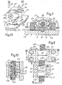
- the numeral 1 very summarily indicates a load bearing structure, to which a support assembly, indicated generically with 3, must be attached; said assembly 3 must cooperate with a threaded bar 5, rotation of which obliges axial movement of the assembly 3 and therefore of the structure 1 attached thereto.
- the assembly 3 comprises a modular support 7, which forms a through seat 7A to house a movement nut 9; the nut rests against a stop 7B formed in the seat 7A, and is locked against rotation with respect to the support 7.
- the modular support 7 has through holes 10 - in this case four in number - to receive screws 12 for attaching the modular support 7 to the load bearing structure 1.
- the assembly of the support 7 and of the nut 9 can be attached to the load bearing structure 1 simply by providing on said load bearing structure holes 14 positioned corresponding to the position of the holes 10 produced in the block of the modular support 7.
- the modular support 7 inferiorly (looking at the drawing) has a transverse housing 16, partially received in which is a tongue 17, projecting partially under the modular support 7.
- a transverse seat 18 with respect to the axis of the seat 7A, suitable to receive the projecting portion of the tongue 17, must be produced in the structure 1.
- the tongue 17 can also be dimensioned to interfere with the nut 9, to thus also perform the function of blocking the nut 9 against axial and angular movements.
- the tongue can be fixed to the support 7 with screws 19.
- the user of the assembly 3, 7, 9 only requires to prepare on the load bearing structure 1 the threaded holes 14 to engage the screws 12 and the transverse seat 18, without any other need for specific measures, which are instead required when the user must prepare the structure 1 specifically in order to attach components received from the supplier of the assembly of a nut and of a support for said nut.
- the tongue 17 ensures exact positioning of the assembly 3, which is locked with the screws 12.
- Figures 5 to 7 show an embodiment equivalent to the one in Figures 1 to 4 with an assembly 23 intended to cooperate with a threaded bar 25.
- the assembly 23 comprises a modular support 27 which forms a through seat 27A with axial stop 27B for a nut 29 similar to the one 9, but differing therefrom due to the presence of a flanging 29A which is received in a housing 27C formed coaxially to the through seat 27A, 27B produced in the support 27.
- optional accessories can be provided, such as felt wear pads 32, 33 and optional manifolds 34 for rubber sleeves combined with the threaded bar 25.
- the modular support 27 is attached - as in the previous case - using screws 28 similar to those 12 for attaching to the load bearing structure 1, and with the advantages already mentioned.
- the support 27 is positioned with the aid of a tongue 35 partly received in a transverse seat 36 in the structure 31 (equivalent to the one 1) and partly in a seat 37 ( Figure 6 ) in the support 27.
- the nut 29 is locked rotatingly with respect to the support 27, with screws 29E, which pass through the flange. 29A to be screwed into specific threaded holes in the support 27.
- the accessories such as those 32 and 33, are attached suitably, for example with screws, to the support 27.
- a lubrication orifice 38 is provided (see Figure 6 ) in the support 27 for lubrication, which is supplied for the inside of the nut 29 (and similarly of the nut 9 in Figures 1 to 4 ) through a passage 39, which reaches the annular groove 29F (and 9F respectively) produced in the seat or preferably in the nut; from the annular groove 29F the lubricant can reach - through one or more passages 29G - the inner threaded hole of the respective nut.
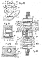
- Figures 8 to 11 show an embodiment providing an arrangement similar to that of the previous embodiments with a threaded bar 45, a support 57 for a movement nut 59 (similar to the one 9 or 29). However, in this embodiment, there is also a supplementary unit 43 with a supplementary support 47 and a supplementary nut 49, to reduce and eliminate any clearance that may occur during progressive wear of the movement system.
- This embodiment provides for a modular support 57 with through seat 57A for a nut 59, which rests against a stop 57B.
- the modular support 57 can be attached by means of screws 61, which pass through said support and are screwed into holes 63 in the structure 54.
- a transverse tongue 65 is provided, partly received in a transverse seat 67 of the structure 54, and partly in a trace 66 produced in the support 47; said trace 66 and the tongue 65 can have dimensions which interfere in the seat 57A to lock, also axially and angularly, the movement of the nut 59; all according to the previous embodiments.
- the unit 43 comprises the supplementary modular support 47 which has a through seat 47A for the supplementary nut 49, which is received in said through seat 47A and which rests against a stop 47B oriented opposite the axial stop 57B for the nut 59.
- Produced in the supplementary modular support 47 are longitudinal guides 51 - i.e. parallel to the axis of the seat 47A and of the threaded bar 45 - with which fixing clamps 53 for attaching to the load bearing structure 54 (corresponding to those 1 and 31 in the previous examples) can cooperate by means of screws 55 that pass through holes of the clamps 53 to reach threaded holes 56 produced in the load-bearing structure 54.
- said further support 47 can be attached to the load bearing structure with locking screws that pass through the support with slotted holes to allow adjustment.
- the supplementary support 47 is equipped with a tongue 70 which extends longitudinally and is formed by a transverse member 71 received and fastened with screws 71A in a transverse trace 72, which interferes with the seat 47A and with the nut 49 to lock it longitudinally and angularly in the support 47.
- the embodiment in Figures 12 to 15 is similar to the embodiment in Figures 8 to 11 , but includes accessories such as felt wear pads 82 and 84 for external protection of the nuts 89 and 99 equivalent to those 49 and 59 in the example in Figures 8 to 11 , but differing with respect thereto due to being equipped with flanges 89A and 99A, and with a dust seal 86, to protect the gap between the modular support 87 (similar to the one 47) and the fixed modular support 97 (similar to the one 57).
- the support 97 is attached in a fixed manner to the load bearing structure 94 (equivalent to the one 54) while the modular support 87 can be adjusted by providing fixing clamps 93 (similar to those 53).
- the support 87 is guided to slide limitedly by means of a tongue 99 partly received in the support 87 and partly and slidingly in a longitudinal seat 101 produced in the structure 94.
- the modular support 97 is instead constrained to the structure 94, as well as by the screws 103, also by a tongue 104 which is partly received in a transverse seat 105 produced in said support 97, and partly in a transverse seat 106 produced in the structure 94, in which seat the tongue 104 can slide limitedly, all for similar functions to those indicated with reference to Figures 8 to 11 .
- the assembly described can be installed on the load bearing structure simply by providing, for attachment, threaded holes in positions easily controllable by means of a template. This allows fast attachment of an assembly provided by the specialized manufacturer of movement systems with threaded bar and cooperating nut.
Landscapes
- Engineering & Computer Science (AREA)
- General Engineering & Computer Science (AREA)
- Mechanical Engineering (AREA)
- Transmission Devices (AREA)
- Pivots And Pivotal Connections (AREA)
- Mutual Connection Of Rods And Tubes (AREA)
- Chair Legs, Seat Parts, And Backrests (AREA)
- Standing Axle, Rod, Or Tube Structures Coupled By Welding, Adhesion, Or Deposition (AREA)
- Seats For Vehicles (AREA)
Claims (6)
- Stützanordnung für wenigstens horizontale Bewegungen mittels einer Kupplung zwischen einer Gewindestange (45; 114) und einer Mutter (59; 99) mit einer durchgehenden Gewindebohrung, mit:einem Modulhalter (57; 97) mit Löchern für Schrauben zum Befestigen einer tragfähigen Struktur (54; 94) und mit einem durchgehenden Sitz (57A) und einer Mutter (59; 99), die in dem durchgehenden Sitz (57A) aufgenommen werden kann; dadurch gekennzeichnet, dass die Anordnung einen weiteren bewegbaren Modulhalter (57; 87) mit einem durchgehenden Sitz (47A) für eine zusätzliche Mutter (49; 89) aufweist, wobei die zwei Muttern (49, 59; 89, 99) für die zwei Halter (47, 57; 87, 97) mit entsprechenden axialen Anschlägen (47B, 57B) einander gegenüberliegend kooperieren und der weitere bewegbare Halter (47; 87) auf variable Weise mit Bezug auf den Modulhalter (57; 97) der Mutter (59; 99) sperrbar ist, um den axialen Spalt zwischen den zwei Muttern (49, 59; 89, 99) einzustellen.
- Stützanordnung nach Anspruch 1, dadurch gekennzeichnet, dass ein axialer Anschlag (57B) in dem durchgehenden Sitz (57A) ausgebildet ist.
- Stützanordnung nach Anspruch 1 oder 2, dadurch gekennzeichnet, dass die Mutter (99) einen Flansch (99A) aufweist und dass in dem Modulhalter (97) eine Aufnahme mit Löchern für den Flansch ausgebildet ist.
- Stützanordnung nach einem der vorstehenden Ansprüche, dadurch gekennzeichnet, dass die Anordnung wenigstens eine Feder (65) aufweist, die in den Sitzen in der tragfähigen Struktur und in dem Halter aufgenommen ist.
- Stützanordnung nach einem der vorstehenden Ansprüche, dadurch gekennzeichnet, dass Verschleissschutzteile (82, 84) vorgesehen sein können, die zum Schutz des durchgehenden Sitzes dienen.
- Stützanordnung nach einem der vorstehenden Ansprüche, dadurch gekennzeichnet, dass der Modulhalter (97) und der bewegbare Halter (87) Muttern (99, 89) mit entgegengesetzt angeordneten Flanschen aufweisen.
Applications Claiming Priority (3)
| Application Number | Priority Date | Filing Date | Title |
|---|---|---|---|
| ITFI20050126 ITFI20050126A1 (it) | 2005-06-10 | 2005-06-10 | Complesso di supporto per movimentazioni tramite barra filettata e chiocciola operativa e con chiocciola di sicurezza |
| ITFI20050124 ITFI20050124A1 (it) | 2005-06-10 | 2005-06-10 | Un complesso di supporto per movimentazione tramite accoppiamento fra barra filettata e chiocciola con foro passante filettato |
| PCT/IT2006/000423 WO2006131948A2 (en) | 2005-06-10 | 2006-06-07 | A support assembly for receiving a nut coupled to a threaded bar |
Publications (2)
| Publication Number | Publication Date |
|---|---|
| EP1904267A2 EP1904267A2 (de) | 2008-04-02 |
| EP1904267B1 true EP1904267B1 (de) | 2009-07-15 |
Family
ID=36917180
Family Applications (1)
| Application Number | Title | Priority Date | Filing Date |
|---|---|---|---|
| EP06756314A Not-in-force EP1904267B1 (de) | 2005-06-10 | 2006-06-07 | Stützanordnung zur aufnahme einer mit einer gewindestange verbundenen mutter |
Country Status (10)
| Country | Link |
|---|---|
| US (1) | US8079279B2 (de) |
| EP (1) | EP1904267B1 (de) |
| JP (1) | JP5033793B2 (de) |
| KR (1) | KR20080019280A (de) |
| AU (1) | AU2006256384B2 (de) |
| BR (1) | BRPI0613696A2 (de) |
| CA (1) | CA2610590A1 (de) |
| DE (1) | DE602006007853D1 (de) |
| ES (1) | ES2327271T3 (de) |
| WO (1) | WO2006131948A2 (de) |
Families Citing this family (7)
| Publication number | Priority date | Publication date | Assignee | Title |
|---|---|---|---|---|
| DE102011003698B4 (de) * | 2011-02-07 | 2019-05-09 | Schaeffler Technologies AG & Co. KG | Spindelantrieb |
| CN103277476A (zh) * | 2013-04-25 | 2013-09-04 | 苏州市职业大学 | 一种能消除丝杠螺母间隙的装置 |
| CN103624340B (zh) * | 2013-12-12 | 2015-10-07 | 宁波瑞亚紧固件制造有限公司 | 船用柴油机汽缸内运动螺母攻牙机夹具 |
| CN107683253B (zh) * | 2015-04-09 | 2019-12-10 | 格雷奥朗佩特有限公司 | 升降设备 |
| US11383960B2 (en) * | 2019-07-02 | 2022-07-12 | Nabholz Construction Corporation | Drop table with motor feedback |
| US11498817B2 (en) * | 2019-07-02 | 2022-11-15 | Nabholz Construction Corporation | Nut gap monitoring system |
| US11167664B2 (en) * | 2020-04-08 | 2021-11-09 | Adient Engineering and IP GmbH | Safety device |
Family Cites Families (20)
| Publication number | Priority date | Publication date | Assignee | Title |
|---|---|---|---|---|
| US2187390A (en) * | 1938-03-30 | 1940-01-16 | Reliance Elevator Mfg Company | Safety and indicating mechanism for elevators |
| US2734394A (en) * | 1953-08-21 | 1956-02-14 | chauvel | |
| US3398598A (en) * | 1966-10-28 | 1968-08-27 | Bendix Corp | Motion translation device |
| US3533298A (en) * | 1968-08-28 | 1970-10-13 | Gerber Scientific Instr Co | Lead screw and nut mechanism |
| GB2114703B (en) * | 1981-12-04 | 1985-09-04 | Hiroshi Teramachi | Ball screw and nut mechanism and two-speed feed arrangement incorporating same |
| US4872795A (en) * | 1988-09-09 | 1989-10-10 | Dana Corporation | Nut assembly with rotatable sleeve for taking up backlash |
| US5195391A (en) * | 1988-10-31 | 1993-03-23 | Deutsche Star Gmbh | Linear guiding and driving unit |
| JPH0386238U (de) * | 1989-12-25 | 1991-08-30 | ||
| US5239297A (en) * | 1990-08-20 | 1993-08-24 | Kley Victor B | Position-encoded screw and method and system for calibrating a position-encoded screw |
| US5171002A (en) * | 1992-01-06 | 1992-12-15 | Laser Machining, Inc. | Machine tool apparatus |
| JPH05277870A (ja) * | 1992-03-27 | 1993-10-26 | Nippon Thompson Co Ltd | 駆動装置及びこれを具備したxy駆動装置 |
| JPH07221134A (ja) * | 1994-02-04 | 1995-08-18 | Disco Abrasive Syst Ltd | ボールネジとナットによる送り機構 |
| US6338285B2 (en) * | 1996-06-17 | 2002-01-15 | Nsk Ltd. | Feed screw device |
| US5755310A (en) * | 1996-09-17 | 1998-05-26 | Joyce/Dayton Corporation | Ratchet lifting nut assembly |
| JP2000088070A (ja) * | 1998-09-09 | 2000-03-28 | Smc Corp | 電動アクチュエータ |
| JP4436559B2 (ja) * | 2000-11-14 | 2010-03-24 | 日本トムソン株式会社 | 潤滑装置を備えたボールねじ装置 |
| US7278332B2 (en) * | 2002-01-17 | 2007-10-09 | Nsk Ltd. | Linear motion device |
| JP2003232428A (ja) * | 2002-02-12 | 2003-08-22 | Ntn Corp | ボールねじのシール装置 |
| DE20315835U1 (de) * | 2003-10-15 | 2005-02-24 | Dewert Antriebs- Und Systemtechnik Gmbh & Co. Kg | Linearantrieb |
| US7152496B2 (en) | 2003-11-14 | 2006-12-26 | Jaegar Industrial Co. Ltd. | Screw nut assembly of linear actuation device |
-
2006
- 2006-06-07 WO PCT/IT2006/000423 patent/WO2006131948A2/en active Application Filing
- 2006-06-07 AU AU2006256384A patent/AU2006256384B2/en not_active Ceased
- 2006-06-07 US US11/916,715 patent/US8079279B2/en not_active Expired - Fee Related
- 2006-06-07 CA CA002610590A patent/CA2610590A1/en not_active Abandoned
- 2006-06-07 DE DE602006007853T patent/DE602006007853D1/de active Active
- 2006-06-07 ES ES06756314T patent/ES2327271T3/es active Active
- 2006-06-07 KR KR1020087000552A patent/KR20080019280A/ko not_active Application Discontinuation
- 2006-06-07 EP EP06756314A patent/EP1904267B1/de not_active Not-in-force
- 2006-06-07 BR BRPI0613696-6A patent/BRPI0613696A2/pt not_active Application Discontinuation
- 2006-06-07 JP JP2008515381A patent/JP5033793B2/ja not_active Expired - Fee Related
Also Published As
| Publication number | Publication date |
|---|---|
| KR20080019280A (ko) | 2008-03-03 |
| DE602006007853D1 (de) | 2009-08-27 |
| AU2006256384A1 (en) | 2006-12-14 |
| WO2006131948A2 (en) | 2006-12-14 |
| BRPI0613696A2 (pt) | 2011-01-25 |
| ES2327271T3 (es) | 2009-10-27 |
| JP5033793B2 (ja) | 2012-09-26 |
| WO2006131948A3 (en) | 2007-03-08 |
| AU2006256384B2 (en) | 2012-02-09 |
| US20080202286A1 (en) | 2008-08-28 |
| EP1904267A2 (de) | 2008-04-02 |
| US8079279B2 (en) | 2011-12-20 |
| CA2610590A1 (en) | 2006-12-14 |
| JP2008545941A (ja) | 2008-12-18 |
Similar Documents
| Publication | Publication Date | Title |
|---|---|---|
| EP1904267B1 (de) | Stützanordnung zur aufnahme einer mit einer gewindestange verbundenen mutter | |
| US10857912B2 (en) | Screw-based adjustment mechanism, rail comprising such an adjustment mechanism, and seat comprising such a rail | |
| US5911474A (en) | Bicycle seat | |
| CN106555528B (zh) | 用于窗开闭调节器中的滑轮加强的装置和方法 | |
| US9139303B2 (en) | Plinth-mounted seat assembly and mounting sub-assemblies | |
| US7537188B2 (en) | Adjusting device | |
| US10773746B2 (en) | Adjustable steering column assembly | |
| JPH06503636A (ja) | モジュールディスクブレーキ | |
| GB2326200A (en) | Slide puck adjustable bearing system | |
| US7574940B2 (en) | Steering column assembly including anti-rotation device | |
| US7635223B2 (en) | Linear guide device with separate circulatory units | |
| CN101460352B (zh) | 齿轮组件的改进 | |
| US7365304B2 (en) | Angular position measuring device having a movable stop element to limit the axial spring motion between a maching part and a second assembly and measuring system having such an angular position measuring device | |
| EP3694746B1 (de) | Antiklappersystem für fluggastsitzbeine mit positionsbeschränkung | |
| CN210800516U (zh) | 手动六自由度微调平台和具有其的传感器调节机构 | |
| US6742402B1 (en) | Steering-angle sensor | |
| CN212220127U (zh) | 卡扣及车辆 | |
| WO2020204859A1 (en) | A door adjustment mechanism | |
| CN215595295U (zh) | 吊轮 | |
| CN111417567A (zh) | 用于将第一机动车部件紧固到第二机动车部件的机动车紧固系统 | |
| US11805910B2 (en) | Locking device for furniture, rotatable furniture and method for locking a rotatable furniture | |
| US20220326445A1 (en) | Optical Bridge | |
| CN214948019U (zh) | 一种支架装置、装载支架和带有支架装置的产品 | |
| US11298751B2 (en) | Adjustable cartridge for boring bar | |
| JP4396786B2 (ja) | ガイドレールにおける停止部材取付台の固定機構 |
Legal Events
| Date | Code | Title | Description |
|---|---|---|---|
| PUAI | Public reference made under article 153(3) epc to a published international application that has entered the european phase |
Free format text: ORIGINAL CODE: 0009012 |
|
| 17P | Request for examination filed |
Effective date: 20071206 |
|
| AK | Designated contracting states |
Kind code of ref document: A2 Designated state(s): AT BE BG CH CY CZ DE DK EE ES FI FR GB GR HU IE IS IT LI LT LU LV MC NL PL PT RO SE SI SK TR |
|
| DAX | Request for extension of the european patent (deleted) | ||
| 17Q | First examination report despatched |
Effective date: 20080602 |
|
| DAX | Request for extension of the european patent (deleted) | ||
| GRAP | Despatch of communication of intention to grant a patent |
Free format text: ORIGINAL CODE: EPIDOSNIGR1 |
|
| GRAS | Grant fee paid |
Free format text: ORIGINAL CODE: EPIDOSNIGR3 |
|
| GRAA | (expected) grant |
Free format text: ORIGINAL CODE: 0009210 |
|
| AK | Designated contracting states |
Kind code of ref document: B1 Designated state(s): AT BE BG CH CY CZ DE DK EE ES FI FR GB GR HU IE IS IT LI LT LU LV MC NL PL PT RO SE SI SK TR |
|
| REG | Reference to a national code |
Ref country code: CH Ref legal event code: EP Ref country code: GB Ref legal event code: FG4D |
|
| REG | Reference to a national code |
Ref country code: IE Ref legal event code: FG4D |
|
| REF | Corresponds to: |
Ref document number: 602006007853 Country of ref document: DE Date of ref document: 20090827 Kind code of ref document: P |
|
| REG | Reference to a national code |
Ref country code: ES Ref legal event code: FG2A Ref document number: 2327271 Country of ref document: ES Kind code of ref document: T3 |
|
| NLV1 | Nl: lapsed or annulled due to failure to fulfill the requirements of art. 29p and 29m of the patents act | ||
| PG25 | Lapsed in a contracting state [announced via postgrant information from national office to epo] |
Ref country code: AT Free format text: LAPSE BECAUSE OF FAILURE TO SUBMIT A TRANSLATION OF THE DESCRIPTION OR TO PAY THE FEE WITHIN THE PRESCRIBED TIME-LIMIT Effective date: 20090715 Ref country code: SE Free format text: LAPSE BECAUSE OF FAILURE TO SUBMIT A TRANSLATION OF THE DESCRIPTION OR TO PAY THE FEE WITHIN THE PRESCRIBED TIME-LIMIT Effective date: 20090715 Ref country code: FI Free format text: LAPSE BECAUSE OF FAILURE TO SUBMIT A TRANSLATION OF THE DESCRIPTION OR TO PAY THE FEE WITHIN THE PRESCRIBED TIME-LIMIT Effective date: 20090715 Ref country code: IS Free format text: LAPSE BECAUSE OF FAILURE TO SUBMIT A TRANSLATION OF THE DESCRIPTION OR TO PAY THE FEE WITHIN THE PRESCRIBED TIME-LIMIT Effective date: 20091115 Ref country code: LT Free format text: LAPSE BECAUSE OF FAILURE TO SUBMIT A TRANSLATION OF THE DESCRIPTION OR TO PAY THE FEE WITHIN THE PRESCRIBED TIME-LIMIT Effective date: 20090715 |
|
| PG25 | Lapsed in a contracting state [announced via postgrant information from national office to epo] |
Ref country code: LV Free format text: LAPSE BECAUSE OF FAILURE TO SUBMIT A TRANSLATION OF THE DESCRIPTION OR TO PAY THE FEE WITHIN THE PRESCRIBED TIME-LIMIT Effective date: 20090715 Ref country code: NL Free format text: LAPSE BECAUSE OF FAILURE TO SUBMIT A TRANSLATION OF THE DESCRIPTION OR TO PAY THE FEE WITHIN THE PRESCRIBED TIME-LIMIT Effective date: 20090715 Ref country code: PL Free format text: LAPSE BECAUSE OF FAILURE TO SUBMIT A TRANSLATION OF THE DESCRIPTION OR TO PAY THE FEE WITHIN THE PRESCRIBED TIME-LIMIT Effective date: 20090715 Ref country code: SI Free format text: LAPSE BECAUSE OF FAILURE TO SUBMIT A TRANSLATION OF THE DESCRIPTION OR TO PAY THE FEE WITHIN THE PRESCRIBED TIME-LIMIT Effective date: 20090715 |
|
| PG25 | Lapsed in a contracting state [announced via postgrant information from national office to epo] |
Ref country code: PT Free format text: LAPSE BECAUSE OF FAILURE TO SUBMIT A TRANSLATION OF THE DESCRIPTION OR TO PAY THE FEE WITHIN THE PRESCRIBED TIME-LIMIT Effective date: 20091115 Ref country code: BG Free format text: LAPSE BECAUSE OF FAILURE TO SUBMIT A TRANSLATION OF THE DESCRIPTION OR TO PAY THE FEE WITHIN THE PRESCRIBED TIME-LIMIT Effective date: 20091015 |
|
| PG25 | Lapsed in a contracting state [announced via postgrant information from national office to epo] |
Ref country code: DK Free format text: LAPSE BECAUSE OF FAILURE TO SUBMIT A TRANSLATION OF THE DESCRIPTION OR TO PAY THE FEE WITHIN THE PRESCRIBED TIME-LIMIT Effective date: 20090715 Ref country code: RO Free format text: LAPSE BECAUSE OF FAILURE TO SUBMIT A TRANSLATION OF THE DESCRIPTION OR TO PAY THE FEE WITHIN THE PRESCRIBED TIME-LIMIT Effective date: 20090715 Ref country code: EE Free format text: LAPSE BECAUSE OF FAILURE TO SUBMIT A TRANSLATION OF THE DESCRIPTION OR TO PAY THE FEE WITHIN THE PRESCRIBED TIME-LIMIT Effective date: 20090715 Ref country code: CZ Free format text: LAPSE BECAUSE OF FAILURE TO SUBMIT A TRANSLATION OF THE DESCRIPTION OR TO PAY THE FEE WITHIN THE PRESCRIBED TIME-LIMIT Effective date: 20090715 |
|
| PLBE | No opposition filed within time limit |
Free format text: ORIGINAL CODE: 0009261 |
|
| STAA | Information on the status of an ep patent application or granted ep patent |
Free format text: STATUS: NO OPPOSITION FILED WITHIN TIME LIMIT |
|
| PG25 | Lapsed in a contracting state [announced via postgrant information from national office to epo] |
Ref country code: SK Free format text: LAPSE BECAUSE OF FAILURE TO SUBMIT A TRANSLATION OF THE DESCRIPTION OR TO PAY THE FEE WITHIN THE PRESCRIBED TIME-LIMIT Effective date: 20090715 Ref country code: BE Free format text: LAPSE BECAUSE OF FAILURE TO SUBMIT A TRANSLATION OF THE DESCRIPTION OR TO PAY THE FEE WITHIN THE PRESCRIBED TIME-LIMIT Effective date: 20090715 |
|
| 26N | No opposition filed |
Effective date: 20100416 |
|
| PG25 | Lapsed in a contracting state [announced via postgrant information from national office to epo] |
Ref country code: GR Free format text: LAPSE BECAUSE OF FAILURE TO SUBMIT A TRANSLATION OF THE DESCRIPTION OR TO PAY THE FEE WITHIN THE PRESCRIBED TIME-LIMIT Effective date: 20091016 |
|
| PG25 | Lapsed in a contracting state [announced via postgrant information from national office to epo] |
Ref country code: MC Free format text: LAPSE BECAUSE OF NON-PAYMENT OF DUE FEES Effective date: 20100630 |
|
| REG | Reference to a national code |
Ref country code: CH Ref legal event code: PL |
|
| PG25 | Lapsed in a contracting state [announced via postgrant information from national office to epo] |
Ref country code: IT Free format text: LAPSE BECAUSE OF FAILURE TO SUBMIT A TRANSLATION OF THE DESCRIPTION OR TO PAY THE FEE WITHIN THE PRESCRIBED TIME-LIMIT Effective date: 20090715 |
|
| PG25 | Lapsed in a contracting state [announced via postgrant information from national office to epo] |
Ref country code: IE Free format text: LAPSE BECAUSE OF NON-PAYMENT OF DUE FEES Effective date: 20100607 Ref country code: LI Free format text: LAPSE BECAUSE OF NON-PAYMENT OF DUE FEES Effective date: 20100630 Ref country code: CH Free format text: LAPSE BECAUSE OF NON-PAYMENT OF DUE FEES Effective date: 20100630 |
|
| PG25 | Lapsed in a contracting state [announced via postgrant information from national office to epo] |
Ref country code: CY Free format text: LAPSE BECAUSE OF FAILURE TO SUBMIT A TRANSLATION OF THE DESCRIPTION OR TO PAY THE FEE WITHIN THE PRESCRIBED TIME-LIMIT Effective date: 20090715 |
|
| PG25 | Lapsed in a contracting state [announced via postgrant information from national office to epo] |
Ref country code: HU Free format text: LAPSE BECAUSE OF FAILURE TO SUBMIT A TRANSLATION OF THE DESCRIPTION OR TO PAY THE FEE WITHIN THE PRESCRIBED TIME-LIMIT Effective date: 20100116 Ref country code: LU Free format text: LAPSE BECAUSE OF NON-PAYMENT OF DUE FEES Effective date: 20100607 |
|
| PG25 | Lapsed in a contracting state [announced via postgrant information from national office to epo] |
Ref country code: TR Free format text: LAPSE BECAUSE OF FAILURE TO SUBMIT A TRANSLATION OF THE DESCRIPTION OR TO PAY THE FEE WITHIN THE PRESCRIBED TIME-LIMIT Effective date: 20090715 |
|
| REG | Reference to a national code |
Ref country code: FR Ref legal event code: PLFP Year of fee payment: 10 |
|
| REG | Reference to a national code |
Ref country code: FR Ref legal event code: PLFP Year of fee payment: 11 |
|
| REG | Reference to a national code |
Ref country code: FR Ref legal event code: PLFP Year of fee payment: 12 |
|
| REG | Reference to a national code |
Ref country code: FR Ref legal event code: PLFP Year of fee payment: 13 |
|
| PGFP | Annual fee paid to national office [announced via postgrant information from national office to epo] |
Ref country code: DE Payment date: 20180615 Year of fee payment: 13 |
|
| PGFP | Annual fee paid to national office [announced via postgrant information from national office to epo] |
Ref country code: FR Payment date: 20180614 Year of fee payment: 13 |
|
| PGFP | Annual fee paid to national office [announced via postgrant information from national office to epo] |
Ref country code: ES Payment date: 20180711 Year of fee payment: 13 Ref country code: GB Payment date: 20180614 Year of fee payment: 13 |
|
| REG | Reference to a national code |
Ref country code: DE Ref legal event code: R119 Ref document number: 602006007853 Country of ref document: DE |
|
| GBPC | Gb: european patent ceased through non-payment of renewal fee |
Effective date: 20190607 |
|
| PG25 | Lapsed in a contracting state [announced via postgrant information from national office to epo] |
Ref country code: GB Free format text: LAPSE BECAUSE OF NON-PAYMENT OF DUE FEES Effective date: 20190607 Ref country code: DE Free format text: LAPSE BECAUSE OF NON-PAYMENT OF DUE FEES Effective date: 20200101 |
|
| PG25 | Lapsed in a contracting state [announced via postgrant information from national office to epo] |
Ref country code: FR Free format text: LAPSE BECAUSE OF NON-PAYMENT OF DUE FEES Effective date: 20190630 |
|
| REG | Reference to a national code |
Ref country code: ES Ref legal event code: FD2A Effective date: 20201027 |
|
| PG25 | Lapsed in a contracting state [announced via postgrant information from national office to epo] |
Ref country code: ES Free format text: LAPSE BECAUSE OF NON-PAYMENT OF DUE FEES Effective date: 20190608 |