EP1903302B1 - Entfernungsmesser - Google Patents
Entfernungsmesser Download PDFInfo
- Publication number
- EP1903302B1 EP1903302B1 EP07104404A EP07104404A EP1903302B1 EP 1903302 B1 EP1903302 B1 EP 1903302B1 EP 07104404 A EP07104404 A EP 07104404A EP 07104404 A EP07104404 A EP 07104404A EP 1903302 B1 EP1903302 B1 EP 1903302B1
- Authority
- EP
- European Patent Office
- Prior art keywords
- unit
- signal
- measuring beam
- modulation
- phase difference
- Prior art date
- Legal status (The legal status is an assumption and is not a legal conclusion. Google has not performed a legal analysis and makes no representation as to the accuracy of the status listed.)
- Active
Links
- 238000001514 detection method Methods 0.000 claims description 55
- 238000005259 measurement Methods 0.000 claims description 34
- 238000005070 sampling Methods 0.000 claims description 29
- 238000006243 chemical reaction Methods 0.000 claims description 19
- 230000000630 rising effect Effects 0.000 claims description 18
- 230000005484 gravity Effects 0.000 claims description 5
- 238000000034 method Methods 0.000 description 28
- 238000012545 processing Methods 0.000 description 22
- 238000010586 diagram Methods 0.000 description 8
- 238000012935 Averaging Methods 0.000 description 6
- 230000003287 optical effect Effects 0.000 description 6
- 238000002366 time-of-flight method Methods 0.000 description 5
- 230000000694 effects Effects 0.000 description 3
- 230000002093 peripheral effect Effects 0.000 description 3
- 230000003111 delayed effect Effects 0.000 description 2
- 238000013461 design Methods 0.000 description 2
- 238000012544 monitoring process Methods 0.000 description 2
- 230000008707 rearrangement Effects 0.000 description 2
- 230000001131 transforming effect Effects 0.000 description 2
- 230000005856 abnormality Effects 0.000 description 1
- 238000010276 construction Methods 0.000 description 1
- 230000003247 decreasing effect Effects 0.000 description 1
- 230000000593 degrading effect Effects 0.000 description 1
- 238000002474 experimental method Methods 0.000 description 1
- 238000001914 filtration Methods 0.000 description 1
- 230000010354 integration Effects 0.000 description 1
- 230000003993 interaction Effects 0.000 description 1
- 230000001678 irradiating effect Effects 0.000 description 1
- 230000031700 light absorption Effects 0.000 description 1
- 239000000463 material Substances 0.000 description 1
- 230000010355 oscillation Effects 0.000 description 1
- 239000004065 semiconductor Substances 0.000 description 1
- 230000035945 sensitivity Effects 0.000 description 1
- 230000001360 synchronised effect Effects 0.000 description 1
- 238000012546 transfer Methods 0.000 description 1
Images


Classifications
-
- G—PHYSICS
- G01—MEASURING; TESTING
- G01S—RADIO DIRECTION-FINDING; RADIO NAVIGATION; DETERMINING DISTANCE OR VELOCITY BY USE OF RADIO WAVES; LOCATING OR PRESENCE-DETECTING BY USE OF THE REFLECTION OR RERADIATION OF RADIO WAVES; ANALOGOUS ARRANGEMENTS USING OTHER WAVES
- G01S17/00—Systems using the reflection or reradiation of electromagnetic waves other than radio waves, e.g. lidar systems
- G01S17/02—Systems using the reflection of electromagnetic waves other than radio waves
- G01S17/06—Systems determining position data of a target
- G01S17/08—Systems determining position data of a target for measuring distance only
- G01S17/10—Systems determining position data of a target for measuring distance only using transmission of interrupted, pulse-modulated waves
-
- G—PHYSICS
- G01—MEASURING; TESTING
- G01S—RADIO DIRECTION-FINDING; RADIO NAVIGATION; DETERMINING DISTANCE OR VELOCITY BY USE OF RADIO WAVES; LOCATING OR PRESENCE-DETECTING BY USE OF THE REFLECTION OR RERADIATION OF RADIO WAVES; ANALOGOUS ARRANGEMENTS USING OTHER WAVES
- G01S7/00—Details of systems according to groups G01S13/00, G01S15/00, G01S17/00
- G01S7/48—Details of systems according to groups G01S13/00, G01S15/00, G01S17/00 of systems according to group G01S17/00
- G01S7/497—Means for monitoring or calibrating
-
- G—PHYSICS
- G01—MEASURING; TESTING
- G01S—RADIO DIRECTION-FINDING; RADIO NAVIGATION; DETERMINING DISTANCE OR VELOCITY BY USE OF RADIO WAVES; LOCATING OR PRESENCE-DETECTING BY USE OF THE REFLECTION OR RERADIATION OF RADIO WAVES; ANALOGOUS ARRANGEMENTS USING OTHER WAVES
- G01S17/00—Systems using the reflection or reradiation of electromagnetic waves other than radio waves, e.g. lidar systems
- G01S17/02—Systems using the reflection of electromagnetic waves other than radio waves
- G01S17/06—Systems determining position data of a target
- G01S17/08—Systems determining position data of a target for measuring distance only
- G01S17/32—Systems determining position data of a target for measuring distance only using transmission of continuous waves, whether amplitude-, frequency-, or phase-modulated, or unmodulated
- G01S17/36—Systems determining position data of a target for measuring distance only using transmission of continuous waves, whether amplitude-, frequency-, or phase-modulated, or unmodulated with phase comparison between the received signal and the contemporaneously transmitted signal
Definitions
- the present invention relates to a rangefinder that has: a light source for outputting a measuring beam; an AM modulation unit for AM modulating the measuring beam with a modulation signal consisting of a sinusoidal wave; a light receiving unit for detecting a reflected beam that is part of the measuring beam modulated by the AM modulation unit and reflected by a measurement object; a phase difference detection unit for finding a phase difference between the measuring beam and the reflected beam; and a distance arithmetic unit for calculating a distance to the measurement object based on the phase difference detected by the phase difference detection unit.
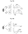
- a laser rangefinder for measuring a distance by modulating a measuring beam outputted from a laser light source LD, irradiating it onto an object X, and detecting the reflected beam from the object X with a photodetector PD, as modulation methods of the measuring beam, two kinds of methods of the AM (Amplitude Modulation) method and the TOF (Time of Flight) method have been put into practical use.
- the AM method is a method where, as shown in FIG.
- the measuring beam being AM modulated with a sinusoidal wave and its reflected beam are subjected to photoelectric exchange, and the phase difference ⁇ between these signals is calculated, and a distance is calculated from the phase difference ⁇ ;
- the TOF method is a method where, as shown in FIG. 9B and Formula 2, the measuring beam modulated to be pulses and its reflected beam are subjected to photoelectric exchange, and a distance is calculated from a delay time ⁇ t between these signals.
- L designates a distance to the object, C the velocity of light, f a modulation frequency, ⁇ the phase difference, and ⁇ t the delay time.
- Rangefinders of this kind are used for a vision sensor of a robot and an unmanned transfer vehicle, an open/shut sensor of a door, a monitor sensor for detecting existence/absence of an intruder into a monitoring area, further a safety sensor that detects a human or an object approaching a danger apparatus and stops it safely, and the like.
- a rangefinder is used in the case of recognizing a shape of a vehicle and a shape of a human.
- the ETC system it is used as a sensor for determining a type of a vehicle and counting the number of passing vehicles and as a monitoring sensor for detecting crowdedness and a flow of people by counting the number of people.
- the AM method has a characteristic that multiple measuring points for phase difference calculation can be set up and accordingly averaging processing of distance calculation is easy, which results in a higher measurement accuracy, it presents a problem that it is impossible to measure accurate distance when the phase delay exceeds one period of the modulation frequency.
- U.S. Pat. No. 5180992 discloses a technique whereby the measuring beam is modulated by mutually different three kinds of modulation frequencies and a correct distance is determined from the calculated distance values based on reflected beams corresponding to the respective frequencies. In this case, the accuracy of distance measurement is governed by a signal having the highest frequency.
- the TOF method since a laser beam with a short emission pulse width is used, it has a feature that emission intensity can be set high compared with the AM method and accordingly detection sensitivity is high; therefore, it becomes possible to measure a long distance while satisfying Class 1 of International Standard for the Safety of Laser Products IEC (International Electrotechnical Commission) 60825-1.
- U.S. Pat. No. 5455669 discloses a technique whereby the reflection signal is measured by using a rising edge signal and a falling edge signal of the counter of a 1.5 GHz clock signal for measurement, and thereby a distance is measured with a resolution of 3 GHz.
- the U.S. Pat. No. 5180992 also poses a problem that it is necessary to irradiate measuring beams modulated with three kinds of frequencies to measure one point, which lengthens emission duration, and accordingly it is difficult to satisfy a regulation of Class 1 of Safety Standard IEC60825-1, which is intended to assure the safety of a laser beam required by the laser rangefinder adapted for general environment to the human eye.
- the AM method is used being limited to a rangefinder of a red laser that satisfies Class 2 of Safety Standard IEC60825-1 in limited environments, such as a case where a detection object made up of a retroreflector etc. is disposed in a predetermined movement area and is used to detect a travelling locus of crane equipment moving on a predetermined route.
- US-A-2004/135992 discloses a rangefinder according to the preamble of claim 1.
- the object of the present invention is, in view of the above-mentioned problem, to provide a rangefinder that can shorten the emission duration and can correct a wavenumber error while adopting the AM method.
- the present invention provides a rangefinder according to claim 1.
- the rangefinder according to the present invention has an AD conversion unit that converts an analog reflection signal corresponding to the reflected beam detected by the light receiving unit into a digital reflection signal with a sampling signal that is shifted in frequency from the modulation signal and comes into synchronization to a specific phase of the modulation signal once every N times, wherein the digital reflection signal as converted by the AD conversion unit is Fourier transformed to detect the phase difference by the phase difference detection unit.
- the phase difference detection unit detects the phase difference by Fourier transforming a digital reflection signal as converted by the AD conversion unit that is subjected to averaging processing over a plurality of modulation periods at sampling timings for each corresponding phase in the respective period.
- the rangefinder has an AD conversion unit that converts an analog reflection signal corresponding to the reflected beam detected by the light receiving unit into the digital reflection signal with the sampling signal that is shifted in frequency from the modulation signal and synchronizes with a specific phase of the modulation signal once every N times, wherein the wavenumber detection unit calculates average values for the digital reflection signal as converted by the AD conversion unit within one modulation period while a time is shifted by one sampling timing each time to get one average value, differential calculus is performed on an average waveform obtained by arranging the average values in time sequence, and the wave position of the sinusoidal wave is calculated based on a timing showing a position of the center of gravity of an obtained differential waveform and an output timing of the measuring beam.
- the rangefinder has a determination unit that calculates average values for the digital reflection signal as converted by the AD conversion unit within one modulation period while a time is shifted by one sampling timing each time to get one average value, and determines existence/presence of disturbance based on an average waveform obtained by arranging the average values in time sequence, from its rising edge to its falling edge.
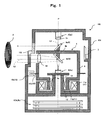
- a scanning rangefinder 100 is constructed such that in a substantially cylindrical casing 101 covered with a light absorption member whose inner wall surface absorbs stray light, such as blackout curtains, a light projection unit 3 for outputting a measuring beam and a light receiving unit 5 for detecting a reflected beam are arranged being opposed to each other, and a scan unit 4 for scanning the measuring beam is disposed between the light projection unit 3 and the light receiving unit 5.
- the scan unit 4 is equipped with a rotating body 8 rotating about a predetermined rotating shaft center P, a deflection mirror 9 rotating as one body with the rotating body 8, and a motor 11 for driving the rotating body 8 to rotate.
- the rotating body 8 consists of a surrounding wall 8a in the form of a cylinder whose diameter in the lower end is reduced and a top plate part 8b, and is supported rotatably by a hollow shaft 13 through a bearing 12 provided in its inner circumferential surface.
- the deflection mirror 9 consists of a first deflection mirror 9a disposed on the top face of the top plate part 8b of the rotating body 8 and a second deflection mirror 9b disposed on the underside of the top plate part 8b, each being arranged with a tilt angle of approximately 45° to the rotating shaft center P.
- the motor 11 consists of a rotor made up of a magnet 11b fixed to a peripheral surface of the lower end of the surrounding wall 8a being reduced in diameter and a stator made up of a coil 11a disposed on the casing side, and is configured to allow the rotating body 8 to rotate about the rotating shaft center P by interaction between the coil 11a and the magnet 11b.
- a slit plate 15a having an optical slit is provided on the peripheral surface of the rotating body 8 and a photointerrupter 15b is disposed on a rotation path of the slit plate 15a, and these members constitute a scan angle detection unit 15 for detecting a scan angle of the rotating body 8.
- the light projection unit 3 is constructed to have a light source 3a made up of a light emitting element using a semiconductor laser and a drive circuit 3b of the light emitting element.
- the light emitting element is fixedly disposed above the casing 101 so that a light axis L1 of the measuring beam outputted therefrom and the rotating shaft center P may coincide with each other.
- An optical lens 3c for converting the beam into a beam with a constant diameter is disposed on the optical axis L1.
- the light receiving unit 5 is disposed and fixed inside the rotating body 8 so as to be opposed to the light projection unit 3 across the scan unit 4 on the rotating shaft center P, and is constructed to have a photodetector 5a made up of an avalanche photodiode for detecting the reflected beam and a light receiving circuit 5b for amplifying a reflection signal that is subjected to photoelectric exchange by a photodetector 5a.
- a transparent window 102 having a fixed width in the vertical direction so that the measuring beam outputted from the light projection unit 3 may be irradiated to measurement object space by the scan unit 4, and a reflected beam reflected by a measurement object X existing in the measurement object space may be detected by the light receiving unit 5.
- the measuring beam emitted from the light projection unit 3 becomes incident on the first deflection mirror 9a along the optical axis L1, is deflected to a horizontal direction, and is irradiated to the measurement object space through the transparent window 102.
- a reflected beam that is part of a measuring beam inputted from a horizontal direction through the transparent window 102 and reflected by the measurement object is deflected by the second deflection mirror 9b downwardly in the vertical direction and is guided to the light receiving unit 5.
- a light receiving lens 14 for focusing the reflected beam from the measurement object onto the light receiving unit 5 is provided on an optical axis L2 along which the reflected beam is guided to the light receiving unit 5.
- a signal processing board 9 that controls rotation of the scan unit 4 and calculates a distance to the measurement object based on the reflection signal that is emitted from a light emitting element by drive and control and is detected by the light receiving unit 5.
- the signal processing board 9 grasps an orientation in which the measurement object corresponding to the reflected beam exists by calculating a rotation angle of the scan unit 4 based on a pulse signal inputted from the scan angle detection unit 15.
- the transparent window 102 is disposed so as to allow the measuring beam to scan in a range from approximately 180° to 270° about the rotating shaft center P.
- a prism as a light guiding member 7 for guiding reference light for correcting a distance calculated with the reflected beam is disposed.
- the light receiving unit 5 detects the reference light through the light guiding member 7, and in this occasion a reference distance from the light projection unit 3 to the light receiving unit 5 inside the rangefinder is calculated.
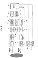
- the signal processing circuit is constructed to have the following, as shown in FIG. 2 : the drive circuit 3b consisting of a burst drive unit for pulse-driving the light source 3a to operate in burst emission and an AM modulation unit for AM modulating the emitted measuring beam with a modulation signal consisting of a sinusoidal wave; the light receiving circuit 5b for amplifying a reflection signal that is the reflected beam subjected to photoelectric exchange at the photodetector 5a; an oscillator 94 for generating a reference clock; an AD conversion unit 90 for converting an analog reflection signal amplified by the light receiving circuit 5b into a digital reflection signal; a phase difference detection unit 91 for finding a phase difference between the measuring beam and the reflected beam; a wavenumber detection unit 92 for detecting a wavenumber of the sinusoidal wave based on a delay time between output of the measuring beam and detection of the reflected beam; a distance
- the AM modulation unit AM modulates the measuring beam in the form of pulses outputted from the light source by the burst drive unit and irradiates it onto the measurement object, and a wavenumber arithmetic unit calculates the distance to the measurement object based on the delay time of the reflected beam. At this time, the wavenumber is found as a quotient obtained by dividing the calculated distance by the wavelength of the modulation signal by the AM modulation unit.
- the phase difference arithmetic unit obtains the phase difference between the measuring beam and the reflected beam. Based on the phase difference, the distance arithmetic unit calculates a tentative distance to the measurement object as within one wavelength of the modulation signal. An accurate distance to the measurement object is calculated by adding a distance corresponding to the wave position found by the wave position arithmetic unit to the obtained tentative distance.
- the distance arithmetic unit 93 is constructed to have a microcomputer and its peripheral circuit, and is configured to control the whole system.
- a motor control circuit 16 for driving the motor 11 and the scan angle detection unit 15 are connected with the distance arithmetic unit 93.
- a motor driving signal When power is turned on in the system, a motor driving signal will be outputted to the motor control circuit 16 from the distance arithmetic unit 93, and the motor control circuit 16 drives the motor 11 at a predetermined speed.
- a pulse signal outputted from the scan angle detection unit 15 is inputted into the distance arithmetic unit 93, and the distance arithmetic unit 93 grasps an output direction of the measuring beam by the scan unit 4 based on said pulse signal.
- a slit plate 15a constituting the scan angle detection unit 15 is formed such that its slit spacing at a predetermined reference position of the rotating body 8, namely, at a position where the reference light is guided to the light receiving unit 5 from the above-mentioned light guiding member 7 is made different from those at other positions. Accordingly, the reference position is grasped based on the waveform of the detected pulse signal, and by counting the pulses from the reference position, a rotation angle from the reference position is calculated.
- the reference clock outputted from the oscillator 94 is divided by a frequency divider 95 in 1/N and is inputted into the drive circuit 3b, generating the modulation signal of a sinusoidal wave on the basis of the frequency division period.
- the light source is driven to a maximum power of 200 mW for a 0.288 ⁇ s in synchronization with a drive pulse of a predetermined period, in this embodiment 18 ⁇ s, and a duty ratio of 1.6% outputted from the distance arithmetic unit 93.
- the measuring beam outputted from the light source is AM modulated with the modulation signal and is outputted.
- the measuring beam is irradiated to the measurement object space as burst light that is an AM modulated sinusoidal wave.
- the light receiving unit 5 detects the reflected beam from the measurement object that is delayed by a propagation time of light compared to the measuring beam and has a shifted phase.
- the AD conversion unit 90 analog-to-digital converts the reflection signal based on a sampling signal that is an output produced by a frequency divider 96 for dividing the reference clock outputted from the oscillator 94 into 1/M.
- the AM method In order to realize a detection distance of 10 m, the AM method requires the measuring beam to have a power (maximum emission output) of 200 mW or more. Then, in order to realize Class 1 of Safety Standard IEC 60825-1 that gives laser light safety requirements, the rangefinder is designed to realize Class 1 by using the measuring beam that is driven to operate in burst emission and thereby lowering an average emission output.
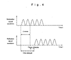
- the reflection signal detected by the light receiving unit 5 is delayed by a time ⁇ t from a rising edge of the modulation signal that has the same frequency and phase as those of the measuring beam and is shifted in phase by ⁇ .
- a time ⁇ t For example, in the case of a modulation frequency of 50 MHz, one wavelength of the signal equals to approximately 3 m.
- a time delay ⁇ t proportional to the distance shown in the figure becomes 2 waves + ⁇ . Therefore, a detection distance is calculated to be (2 + ⁇ /2 ⁇ ) ⁇ 3000 mm.
- the wavenumber detection unit 92 detects a time delay ⁇ t from a rising edge timing of the drive pulse to the rising edge timing of the reflection signal, finds a distance corresponding to said time delay using the above-mentioned Formula 2 based on the time delay ⁇ t, and calculates the wavenumber of the modulation signal as an integer value from a quotient obtained by dividing the distance by a wavelength of the modulation signal.
- the phase difference detection unit 91 calculates a phase delay ⁇ as within one wavelength of the reflection signal with respect to the modulation signal.
- the distance arithmetic unit 93 calculates a distance corresponding to the wavenumber of the modulation signal detected by the wavenumber detection unit 92 and a distance corresponding to the phase delay ⁇ as within one wavelength detected by the phase difference detection unit 91 respectively, and finds the distance to the measurement object from the calculated sum result.
- the reference distance is calculated based on the wavenumber of the modulation signal detected by the wavenumber detection unit 92 and the phase delay ⁇ as within one wavelength detected by the phase difference detection unit 91.
- the reference distance is smaller than the wavelength of the modulation signal, it is not necessary to detect the wavenumber, and a distance corresponding to the phase delay ⁇ as within one wavelength detected by the phase difference detection unit 91 will be the reference distance.
- the reference distance is calculated and the distance to the measurement object detected based on the reflected beam during next one scan is corrected based on said reference distance.
- the distance from the rangefinder 100 to the measurement object and its direction are detected.
- the phase difference detection unit 91 and the wavenumber detection unit 92 will be explained in detail below.
- the phase difference detection unit 91 is constructed to have a rearrangement processing unit 91a for rearranging a reflection signal value that is converted into a digital signal by the AD conversion unit 90 in time sequence and a phase difference calculation unit 91b for Fourier transforming the reflection signal that is configured by rearranging the signal value to detect its phase.
- the sampling signal is shifted in frequency from the modulation signal, becoming a signal that synchronizes with a specific phase of the modulation signal once every N time.
- N is a positive integer value, and when the value of N is decreased, the number of samplings within one wavelength of the modulation signal will decrease. In this case, if the reflection signal suffers distortion due to an unstable reflected beam from the measurement object and a frequency characteristic of an amplifier, phase arithmetic may be led to a mistake. Therefore, it is preferable to adopt normally a value of eight or more.
- sampling timing of a frequency of 250 MHz in the AD conversion unit 90 is made to synchronize with a specific phase of the reflection signal once every nine times (in the figure, sampling point D1), and at other eight sampling timings the reflection signal waveform values are obtained as pieces of amplitude data corresponding to different specific phases within one period of the reflection signal. These pieces of amplitude data are stored in internal memory sequentially corresponding to sampling timings.
- a phase ⁇ of the reflection signal is calculated by performing Fourier transform by applying Formula 3 to values each of which is obtained by averaging pieces of down-converted signal data over eight periods. That is, the phase difference detection unit 91 is configured to Fourier transform the digital reflection signal that is subjected to averaging processing over a plurality of frequency division periods at sampling timings for each corresponding phase in the respective period to detect the phase difference.
- both the sampling signal and the modulation signal are generated on the basis of the reference clock from the oscillator 94 and are synchronized with each other, it is not necessary to calculate a phase of the measuring beam and the calculated phase ⁇ is obtained just as the phase delay ⁇ . Moreover, an effect caused by waveform fluctuation at the time of sampling is small, which enables high-accuracy measurement.
- the wavenumber detection unit 92 is constructed to have an average/differential arithmetic unit 92a that performs differential calculus on an average waveform obtained by arranging the average values within one frequency division period for the digital reflection signal as converted by the AD conversion unit 90 while a time is shifted by one sampling timing each time to get one average value; and a wavenumber calculation unit 92b that calculates the wavenumber of the sinusoidal wave based on the timing showing a position of the center of gravity of the differential waveform obtained by the average/differential arithmetic unit 92a and an output timing of the measuring beam.
- average values for one period of the modulation signal are found while a time is shifted by one sampling timing each time to get one average value for the reflection signal being AD converted, and the average waveform is calculated by arranging the obtained average values in time sequence. Therefore, even when the rising edge timing of detected light suffers variation due to intensity of the reflected beam, a waveform with a smoothed rising edge characteristic can be obtained. Then, the position of the center of gravity of the differential waveform obtained by performing differential calculus on the average waveform like this is set as a rising edge timing of the reflected beam, whereby it becomes possible to calculate the rising edge timing accurately.
- the average/differential arithmetic unit 92a first performs processing in which, for the digital reflection signal D1, D2, ..., D9, D10, ..., D19, ... as converted by the AD conversion unit 90, moving average values of the digital reflection signals (D1, D2, ..., D9), (D10, D11, ..., D 18), ... in one frequency division period are obtained while a time is shifted by one sampling timing each time to get one average value, and the moving average values thus obtained are arranged along the sampling period, whereby a moving average waveform B1, B2, ..., B9, ...is obtained, as shown in the lower part of FIG. 6 .
- the wavenumber calculation unit 92b finds the wavenumber as a quotient obtained by dividing the found time delay ⁇ t by the period of the modulation signal. Thus, since the wave position calculation unit 92b calculates only the wavenumber of the modulation signal, an accuracy of the vertex position W of the deferential edge is not required so much. To calculate the center-of-gravity arithmetic expression, an operation that targets as much number of signals as samplings of one period of the modulation frequency will suffice. However, it is preferable to target the number of sampling equal to two periods, i.e., signals at nine points.
- the light receiving circuit 5b is equipped with a band pass filter with a steep filtering characteristic in order to detect a reflection signal modulated with a single modulation signal, whereby it becomes possible to eliminate noise light entering from the outside effectively.
- the wavenumber calculation unit 92b is further equipped with a determination unit for determining existence/absence of interference light from the outside based on the moving average waveform, from its rising edge to its falling edge.
- the rangefinder can be configured to show error indication in, for example, a display unit provided in the rangefinder.
- the phase difference detection unit 91 is made to perform arithmetic mean processing only on normal pieces of data that is the remainder when the data of the pertinent period is eliminated from the signal data over eight periods, on which normally averaging processing is done for each phase. By this procedure, it becomes possible to calculate the phase ⁇ of the reflection signal without causing reduction in detection accuracy.
- the reflected beam is affected by any disturbance, for example, by a measuring beam of a rangefinder of the same type located near the pertinent rangefinder, a conspicuous fluctuation will be found in a partial waveform from its rising edge to its falling edge of the average waveform. Accordingly, it becomes possible to effectively detect disturbance that cannot be detected by the phase difference detection unit.
- the above-mentioned signal processing block of the phase difference detection unit 91 and the wavenumber detection unit 92 can be made up of an ASIC that is integration of a plurality of logical computing elements, and can be implemented by integrating a digital signal processor therein, if needed.
- the rangefinder is enabled to realize rangefinding with a detection accuracy of approximately 7.5 mm for a detection distance of approximately 10 m.
- the oscillation frequency of the oscillator 94, the division ratio of the frequency divider 95, and the period and duty ratio of a pulse driving signal to the light source are shown just for an example, and can be altered appropriately in the design within a range where an action and an effect of the present invention can be attained. However, an experiment has cleared that in order to realize a measurement accuracy of 10 mm, a modulation signal of 50 MHz or more and the number of detection points of 60 or more are needed.
- the embodiment described above is one embodiment of the present invention, and a concrete configuration of parts, such as a shape, a material, and a circuit configuration, can be altered in the design appropriately within a range where the action and effect by the present invention can be attained.
- the light receiving unit 5 is disposed on the light projection unit 3 side; a deflection mirror consisting of the first deflection mirror 9a and the second deflection mirror 9b provided in the scan unit 4 is made up of a singe deflection mirror; and an optical system for guiding the reflected beam to the light receiving unit 5 is provided.
Landscapes
- Physics & Mathematics (AREA)
- Engineering & Computer Science (AREA)
- Electromagnetism (AREA)
- Computer Networks & Wireless Communication (AREA)
- General Physics & Mathematics (AREA)
- Radar, Positioning & Navigation (AREA)
- Remote Sensing (AREA)
- Optical Radar Systems And Details Thereof (AREA)
- Measurement Of Optical Distance (AREA)
Claims (2)
- Entfernungsmesser (100), umfassend:eine Lichtquelle (3a) zum Ausgeben eines Messstrahls;eine Burst-Treibereinheit zum Pulstreiben der Lichtquelle derart, dass sie bei Burst-Emission betrieben wird;eine AM-Modulationseinheit zum AM-Modulieren des Meßstrahls mit einem Modulationssignal, welches aus einer sinusförmigen Welle besteht;eine Lichtempfangseinheit (5) zum Erfassen eines reflektierten Strahls, der Teil des Messstrahls ist, welcher durch die AM-Modulationseinheit moduliert und durch ein Messobjekt reflektiert wurde;eine Phasendifferenzerfassungseinheit (91) zum Feststellen einer Phasendifferenz zwischen dem Messstrahl und dem reflektierten Strahl;einer Wellenzahlerfassungseinheit (92) zum Erfassen einer Wellenzahl der sinusförmigen Welle basierend auf einer Verzögerungszeit von der Ausgabe des Messstrahls zur Erfassung des reflektierten Strahls;eine Abstandsarithmetikeinheit (93) zum Berechnen eines Abstands zum Messobjekt basierend auf der Wellenzahl, die durch die Wellenzahlerfassungseinheit (92) erfasst wurde, und der Phasendifferenz, die durch die Phasendifferenzerfassungseinheit (91) erfasst wurde,dadurch gekennzeichnet, dass der Entfernungsmesser (100) ferner umfasst:eine AD-Umwandlungseinheit (90) zum Umwandeln eines analogen Reflektionssignals, welches dem reflektierten Strahl entspricht, der durch die Lichtempfangseinheit (5) erfasst wurde, in ein digitales Reflektionssignal mit einem Samplingsignal, welches von dem Modulationssignal Frequenz verschoben ist, und Synchronisieren mit einer bestimmten Phase des Modulationssignals einmal alle N Male, undwobei die Wellenzahlerfassungseinheit (92) dazu ausgelegt ist, Durchschnittswerte für das digitale Reflektionssignal, wie es durch die AD-Umwandlungseinheit (90) umgewandelt wurde, innerhalb einer Modulationsperiode zu berechnen, indem jedes Mal eine Zeit um eine Samplingzeitspanne verschoben ist, um einen Durchschnittswert zu erhalten, eine Differentialrechnung auf einer Durchschnittswellenform durchzuführen, die durch Anordnen der Durchschnittswerte in zeitlicher Folge erhalten ist, und die Wellenzahl der sinusförmigen Welle basierend auf einer Zeitspanne, die eine Position des Schwerpunkts einer erhaltenen differenziellen Wellenform darstellt, und einer Ausgabezeitspanne des Messstrahls zu berechnen.
- Entfernungsmesser (100) nach Anspruch 1, ferner umfassend eine Bestimmungseinheit zum Bestimmen, dass eine Störung aufgetreten ist, wenn eine andere Flanke als eine ansteigende Flanke und eine abfallende Flanke der differenziellen Wellenform, die der Durchschnittswellenform entspricht, erfasst ist.
Applications Claiming Priority (1)
| Application Number | Priority Date | Filing Date | Title |
|---|---|---|---|
| JP2006253833A JP4116053B2 (ja) | 2006-09-20 | 2006-09-20 | 測距装置 |
Publications (3)
| Publication Number | Publication Date |
|---|---|
| EP1903302A2 EP1903302A2 (de) | 2008-03-26 |
| EP1903302A3 EP1903302A3 (de) | 2010-04-21 |
| EP1903302B1 true EP1903302B1 (de) | 2013-02-27 |
Family
ID=38752465
Family Applications (1)
| Application Number | Title | Priority Date | Filing Date |
|---|---|---|---|
| EP07104404A Active EP1903302B1 (de) | 2006-09-20 | 2007-03-19 | Entfernungsmesser |
Country Status (3)
| Country | Link |
|---|---|
| US (1) | US7388655B2 (de) |
| EP (1) | EP1903302B1 (de) |
| JP (1) | JP4116053B2 (de) |
Families Citing this family (43)
| Publication number | Priority date | Publication date | Assignee | Title |
|---|---|---|---|---|
| US7755743B2 (en) * | 2006-10-18 | 2010-07-13 | Panasonic Electric Works Co., Ltd. | Spatial information detecting apparatus |
| US7746450B2 (en) * | 2007-08-28 | 2010-06-29 | Science Applications International Corporation | Full-field light detection and ranging imaging system |
| US8125620B2 (en) * | 2007-10-18 | 2012-02-28 | PulsedLight, LLC | Optical sensor device |
| DE102008045387B4 (de) | 2008-09-02 | 2017-02-09 | Carl Zeiss Ag | Vorrichtung und Verfahren zum Vermessen einer Oberfläche |
| DE102008045386B4 (de) | 2008-09-02 | 2017-07-13 | Carl Zeiss Ag | Vorrichtung und Verfahren zum Bestimmen einer Objektposition |
| JP5572319B2 (ja) * | 2009-01-31 | 2014-08-13 | 株式会社キーエンス | 安全光電スイッチ |
| US9035820B2 (en) * | 2009-03-31 | 2015-05-19 | Nec Corporation | Measurement device, measurement system, measurement method, and program |
| GB2472085A (en) * | 2009-07-24 | 2011-01-26 | Wayne Rudd | Methods and apparatus for determining the time of receipt of a received signal |
| JP5696324B2 (ja) * | 2009-09-29 | 2015-04-08 | 富士通株式会社 | 走行体 |
| US8760631B2 (en) | 2010-01-27 | 2014-06-24 | Intersil Americas Inc. | Distance sensing by IQ domain differentiation of time of flight (TOF) measurements |
| JP5218494B2 (ja) * | 2010-07-30 | 2013-06-26 | オムロン株式会社 | 変位センサ |
| JP2012037294A (ja) * | 2010-08-05 | 2012-02-23 | Jtekt Corp | 超音波計測方法および超音波工作物径測定装置 |
| JP2012093143A (ja) * | 2010-10-25 | 2012-05-17 | Panasonic Corp | 障害物検知装置 |
| WO2012056791A1 (ja) * | 2010-10-26 | 2012-05-03 | アルプス電気株式会社 | 距離測定装置 |
| AT511310B1 (de) * | 2011-04-07 | 2013-05-15 | Riegl Laser Measurement Sys | Verfahren zur entfernungsmessung |
| JP5753449B2 (ja) * | 2011-06-30 | 2015-07-22 | 株式会社トプコン | 光波距離測定方法及び光波距離装置 |
| US9168774B2 (en) * | 2012-01-06 | 2015-10-27 | Zih Corp. | Tri-state detector for detecting types of light |
| JP2013195117A (ja) * | 2012-03-16 | 2013-09-30 | Ricoh Co Ltd | 測距装置 |
| US9354051B2 (en) * | 2012-09-13 | 2016-05-31 | Laser Technology, Inc. | System and method for a rangefinding instrument incorporating pulse and continuous wave signal generating and processing techniques for increased distance measurement accuracy |
| US9879995B2 (en) | 2012-09-13 | 2018-01-30 | Laser Technology, Inc. | System and method for superimposing a virtual aiming mechanism with a projected system beam in a compact laser-based rangefinding instrument |
| DE102012021830A1 (de) * | 2012-11-08 | 2014-05-08 | Valeo Schalter Und Sensoren Gmbh | Optoelektronische Detektionseinrichtung mit einstellbarer Biasspannung eines Avalanche-Photodetektors für ein Kraftfahrzeug, Kraftfahrzeug und entsprechendes Verfahren |
| CN103760566A (zh) * | 2014-01-08 | 2014-04-30 | 苏州新桥电子科技有限公司 | 激光测距系统 |
| US9897690B2 (en) | 2014-10-27 | 2018-02-20 | Laser Technology, Inc. | Technique for a pulse/phase based laser rangefinder utilizing a single photodiode in conjunction with separate pulse and phase receiver circuits |
| JP6455088B2 (ja) * | 2014-11-06 | 2019-01-23 | 株式会社デンソー | 光飛行型測距装置 |
| US10816905B2 (en) * | 2015-04-08 | 2020-10-27 | Cymer, Llc | Wavelength stabilization for an optical source |
| JP6902902B2 (ja) * | 2017-03-30 | 2021-07-14 | 株式会社トプコン | 光波距離計 |
| JP6902901B2 (ja) * | 2017-03-30 | 2021-07-14 | 株式会社トプコン | 光波距離計 |
| JP7290571B2 (ja) | 2017-03-31 | 2023-06-13 | ベロダイン ライダー ユーエスエー,インコーポレイテッド | 統合化されたlidar照明出力制御 |
| CN115575928A (zh) | 2017-05-08 | 2023-01-06 | 威力登激光雷达美国有限公司 | Lidar数据获取与控制 |
| EP3474039B1 (de) * | 2017-10-20 | 2019-09-25 | Sick AG | Entfernungsmessender optoelektronischer sensor und verfahren zur abstandsbestimmung |
| US11340336B2 (en) | 2017-12-07 | 2022-05-24 | Ouster, Inc. | Rotating light ranging system with optical communication uplink and downlink channels |
| WO2019113368A1 (en) * | 2017-12-07 | 2019-06-13 | Ouster, Inc. | Rotating compact light ranging system |
| EP3525004B1 (de) * | 2018-02-08 | 2020-10-14 | Cedes AG | Tof sensor mit prüfsender |
| JP7061364B2 (ja) * | 2018-06-11 | 2022-04-28 | 国立大学法人東京農工大学 | 距離測定装置及び距離測定方法 |
| US10712434B2 (en) | 2018-09-18 | 2020-07-14 | Velodyne Lidar, Inc. | Multi-channel LIDAR illumination driver |
| US11885958B2 (en) | 2019-01-07 | 2024-01-30 | Velodyne Lidar Usa, Inc. | Systems and methods for a dual axis resonant scanning mirror |
| KR102299264B1 (ko) * | 2019-01-16 | 2021-09-07 | 삼성전자주식회사 | 라이다 장치 |
| US20220252702A1 (en) * | 2019-07-09 | 2022-08-11 | The Regents Of The University Of California | Pulsed-Coherent Electronic Front End for Lidar and Radar Detection and Ranging |
| US20220291380A1 (en) * | 2019-07-12 | 2022-09-15 | Sony Group Corporation | Semiconductor device |
| JP7445107B2 (ja) * | 2019-08-05 | 2024-03-07 | 株式会社トリマティス | レーザ測距装置 |
| CN111077512B (zh) * | 2019-11-26 | 2023-12-26 | 歌尔光学科技有限公司 | Tof模组标定方法及系统 |
| JP7417859B2 (ja) * | 2020-03-19 | 2024-01-19 | 株式会社リコー | 距離補正情報の算出方法、測距装置、移動体及びステレオカメラ装置 |
| JP7233628B1 (ja) * | 2022-09-30 | 2023-03-06 | 三菱電機株式会社 | 光制御装置 |
Family Cites Families (12)
| Publication number | Priority date | Publication date | Assignee | Title |
|---|---|---|---|---|
| DE68925998T2 (de) | 1988-06-29 | 1996-09-12 | Topcon Corp | Hochauflösendes Zeitdifferenzmessgerät |
| JPH04154318A (ja) * | 1990-10-18 | 1992-05-27 | Fujitsu Ltd | Pll周波数シンセサイザ |
| JP3141120B2 (ja) | 1992-02-21 | 2001-03-05 | 株式会社トプコン | 位相測定装置及び距離測定装置 |
| US5455669A (en) * | 1992-12-08 | 1995-10-03 | Erwin Sick Gmbh Optik-Elektronik | Laser range finding apparatus |
| JPH1020036A (ja) * | 1996-06-28 | 1998-01-23 | Toyota Central Res & Dev Lab Inc | 距離測定方法および装置 |
| KR100218307B1 (ko) | 1996-07-01 | 1999-09-01 | 구본준 | 반도체 메모리소자의 칼럼디코딩회로 |
| JP2000206244A (ja) | 1999-01-20 | 2000-07-28 | Kubota Corp | 測距装置 |
| EP1311873B1 (de) | 2000-08-25 | 2011-08-10 | Leica Geosystems AG | Verfahren und vorrichtung zur entfernungsmessung |
| EP1576385A2 (de) * | 2002-11-26 | 2005-09-21 | James F. Munro | Vorrichtung zur präzisen distanz- und geschwindigkeitsmessungund verfahren dafür |
| JP4104991B2 (ja) | 2003-01-16 | 2008-06-18 | 株式会社トプコン | 光波距離計 |
| JP4002199B2 (ja) | 2003-02-28 | 2007-10-31 | 株式会社ソキア | 光波距離計 |
| JP3935897B2 (ja) | 2004-06-15 | 2007-06-27 | 北陽電機株式会社 | 光波測距装置 |
-
2006
- 2006-09-20 JP JP2006253833A patent/JP4116053B2/ja active Active
-
2007
- 2007-03-19 EP EP07104404A patent/EP1903302B1/de active Active
- 2007-03-20 US US11/723,542 patent/US7388655B2/en active Active
Also Published As
| Publication number | Publication date |
|---|---|
| JP4116053B2 (ja) | 2008-07-09 |
| US20080088818A1 (en) | 2008-04-17 |
| JP2008076131A (ja) | 2008-04-03 |
| EP1903302A3 (de) | 2010-04-21 |
| US7388655B2 (en) | 2008-06-17 |
| EP1903302A2 (de) | 2008-03-26 |
Similar Documents
| Publication | Publication Date | Title |
|---|---|---|
| EP1903302B1 (de) | Entfernungsmesser | |
| US11467282B2 (en) | Chirped coherent laser radar system and method | |
| US7602485B2 (en) | Optical window contamination detecting device for optical apparatus | |
| EP1901092B1 (de) | Vorrichtung zur Distanzmessung | |
| US8831908B2 (en) | Signal processing apparatus used for operations for range finding and scanning rangefinder | |
| JP5598831B2 (ja) | 走査式測距装置 | |
| US7543750B2 (en) | Laser velocimetric image scanning | |
| EP3428685B1 (de) | Laserradarvorrichtung | |
| EP2690463B1 (de) | Signalverarbeitungvorrichtung eines abstandsmessungsscanners, signalverarbeitungsverfahren und abstandsmessungsscanner | |
| JP2004538492A (ja) | 距離を測定する装置 | |
| JPH1020035A (ja) | レーザ距離測定装置 | |
| JP2012242189A (ja) | 走査式測距装置の信号処理装置、信号処理方法、及び走査式測距装置 | |
| US7408628B2 (en) | Radar apparatus | |
| US20240288558A1 (en) | Optical measuring device and method | |
| CN109116322A (zh) | 一种位移和距离激光雷达系统的回光消除方法 | |
| EP3647812A1 (de) | Empfangsvorrichtung, steuerungsverfahren, programm und speichermedium | |
| JPH09297014A (ja) | レーザレーダ三次元形状計測装置 | |
| US20240118427A1 (en) | Lidar system, vehicle and operation method | |
| EP3715909A1 (de) | Lichtwellenentfernungsmesser | |
| US20220120904A1 (en) | Imaging lidar | |
| JPH08105971A (ja) | マルチパルスによる測距方法とその装置 | |
| US20240094387A1 (en) | Optical sensing system, optical sensing device, and optical sensing method | |
| JPH0921871A (ja) | 半導体レーザ距離測定装置 | |
| JPH09210639A (ja) | 外径測定装置 | |
| WO2004029656A1 (en) | A range finder and method of determining range |
Legal Events
| Date | Code | Title | Description |
|---|---|---|---|
| PUAI | Public reference made under article 153(3) epc to a published international application that has entered the european phase |
Free format text: ORIGINAL CODE: 0009012 |
|
| AK | Designated contracting states |
Kind code of ref document: A2 Designated state(s): AT BE BG CH CY CZ DE DK EE ES FI FR GB GR HU IE IS IT LI LT LU LV MC MT NL PL PT RO SE SI SK TR |
|
| AX | Request for extension of the european patent |
Extension state: AL BA HR MK YU |
|
| PUAL | Search report despatched |
Free format text: ORIGINAL CODE: 0009013 |
|
| AK | Designated contracting states |
Kind code of ref document: A3 Designated state(s): AT BE BG CH CY CZ DE DK EE ES FI FR GB GR HU IE IS IT LI LT LU LV MC MT NL PL PT RO SE SI SK TR |
|
| AX | Request for extension of the european patent |
Extension state: AL BA HR MK RS |
|
| RIC1 | Information provided on ipc code assigned before grant |
Ipc: G01C 15/00 20060101ALI20100315BHEP Ipc: G01C 3/08 20060101AFI20071207BHEP Ipc: G01S 17/10 20060101ALI20100315BHEP |
|
| 17P | Request for examination filed |
Effective date: 20101021 |
|
| AKX | Designation fees paid |
Designated state(s): DE |
|
| AXX | Extension fees paid |
Extension state: HR Payment date: 20101021 Extension state: BA Payment date: 20101021 Extension state: RS Payment date: 20101021 Extension state: MK Payment date: 20101021 Extension state: AL Payment date: 20101021 |
|
| GRAP | Despatch of communication of intention to grant a patent |
Free format text: ORIGINAL CODE: EPIDOSNIGR1 |
|
| GRAS | Grant fee paid |
Free format text: ORIGINAL CODE: EPIDOSNIGR3 |
|
| GRAA | (expected) grant |
Free format text: ORIGINAL CODE: 0009210 |
|
| AK | Designated contracting states |
Kind code of ref document: B1 Designated state(s): DE |
|
| REG | Reference to a national code |
Ref country code: DE Ref legal event code: R096 Ref document number: 602007028647 Country of ref document: DE Effective date: 20130425 |
|
| PLBE | No opposition filed within time limit |
Free format text: ORIGINAL CODE: 0009261 |
|
| STAA | Information on the status of an ep patent application or granted ep patent |
Free format text: STATUS: NO OPPOSITION FILED WITHIN TIME LIMIT |
|
| 26N | No opposition filed |
Effective date: 20131128 |
|
| REG | Reference to a national code |
Ref country code: DE Ref legal event code: R097 Ref document number: 602007028647 Country of ref document: DE Effective date: 20131128 |
|
| P01 | Opt-out of the competence of the unified patent court (upc) registered |
Effective date: 20230419 |
|
| PGFP | Annual fee paid to national office [announced via postgrant information from national office to epo] |
Ref country code: DE Payment date: 20240130 Year of fee payment: 18 |