EP1902805A2 - Werkzeug für die Bearbeitung eines Werkstücks - Google Patents
Werkzeug für die Bearbeitung eines Werkstücks Download PDFInfo
- Publication number
- EP1902805A2 EP1902805A2 EP07014752A EP07014752A EP1902805A2 EP 1902805 A2 EP1902805 A2 EP 1902805A2 EP 07014752 A EP07014752 A EP 07014752A EP 07014752 A EP07014752 A EP 07014752A EP 1902805 A2 EP1902805 A2 EP 1902805A2
- Authority
- EP
- European Patent Office
- Prior art keywords
- tool
- threads
- region
- flute
- cutting edge
- Prior art date
- Legal status (The legal status is an assumption and is not a legal conclusion. Google has not performed a legal analysis and makes no representation as to the accuracy of the status listed.)
- Granted
Links
- 238000003754 machining Methods 0.000 title claims description 10
- 238000005520 cutting process Methods 0.000 claims description 69
- 238000010079 rubber tapping Methods 0.000 claims description 45
- 230000002093 peripheral effect Effects 0.000 claims description 12
- 230000007423 decrease Effects 0.000 claims description 3
- 229910000831 Steel Inorganic materials 0.000 description 9
- 239000010959 steel Substances 0.000 description 9
- 238000004519 manufacturing process Methods 0.000 description 4
- 238000005121 nitriding Methods 0.000 description 1
- 238000007790 scraping Methods 0.000 description 1
Images


Classifications
-
- B—PERFORMING OPERATIONS; TRANSPORTING
- B23—MACHINE TOOLS; METAL-WORKING NOT OTHERWISE PROVIDED FOR
- B23G—THREAD CUTTING; WORKING OF SCREWS, BOLT HEADS, OR NUTS, IN CONJUNCTION THEREWITH
- B23G5/00—Thread-cutting tools; Die-heads
- B23G5/02—Thread-cutting tools; Die-heads without means for adjustment
- B23G5/06—Taps
-
- B—PERFORMING OPERATIONS; TRANSPORTING
- B23—MACHINE TOOLS; METAL-WORKING NOT OTHERWISE PROVIDED FOR
- B23G—THREAD CUTTING; WORKING OF SCREWS, BOLT HEADS, OR NUTS, IN CONJUNCTION THEREWITH
- B23G2200/00—Details of threading tools
- B23G2200/04—Tools with negative cutting angles
-
- B—PERFORMING OPERATIONS; TRANSPORTING
- B23—MACHINE TOOLS; METAL-WORKING NOT OTHERWISE PROVIDED FOR
- B23G—THREAD CUTTING; WORKING OF SCREWS, BOLT HEADS, OR NUTS, IN CONJUNCTION THEREWITH
- B23G2200/00—Details of threading tools
- B23G2200/48—Spiral grooves, i.e. spiral flutes
-
- B—PERFORMING OPERATIONS; TRANSPORTING
- B23—MACHINE TOOLS; METAL-WORKING NOT OTHERWISE PROVIDED FOR
- B23G—THREAD CUTTING; WORKING OF SCREWS, BOLT HEADS, OR NUTS, IN CONJUNCTION THEREWITH
- B23G2210/00—Details of threads produced
- B23G2210/04—Internal threads
-
- B—PERFORMING OPERATIONS; TRANSPORTING
- B23—MACHINE TOOLS; METAL-WORKING NOT OTHERWISE PROVIDED FOR
- B23G—THREAD CUTTING; WORKING OF SCREWS, BOLT HEADS, OR NUTS, IN CONJUNCTION THEREWITH
- B23G2210/00—Details of threads produced
- B23G2210/16—Multiple start threads
-
- Y—GENERAL TAGGING OF NEW TECHNOLOGICAL DEVELOPMENTS; GENERAL TAGGING OF CROSS-SECTIONAL TECHNOLOGIES SPANNING OVER SEVERAL SECTIONS OF THE IPC; TECHNICAL SUBJECTS COVERED BY FORMER USPC CROSS-REFERENCE ART COLLECTIONS [XRACs] AND DIGESTS
- Y10—TECHNICAL SUBJECTS COVERED BY FORMER USPC
- Y10T—TECHNICAL SUBJECTS COVERED BY FORMER US CLASSIFICATION
- Y10T408/00—Cutting by use of rotating axially moving tool
- Y10T408/86—Tool-support with means to permit positioning of the Tool relative to support
- Y10T408/87—Tool having stepped cutting edges
- Y10T408/8725—Tool having stepped cutting edges including means to permit relative axial positioning of edges
- Y10T408/8734—Tool having stepped cutting edges including means to permit relative axial positioning of edges including central Tool axially movable relative to support
-
- Y—GENERAL TAGGING OF NEW TECHNOLOGICAL DEVELOPMENTS; GENERAL TAGGING OF CROSS-SECTIONAL TECHNOLOGIES SPANNING OVER SEVERAL SECTIONS OF THE IPC; TECHNICAL SUBJECTS COVERED BY FORMER USPC CROSS-REFERENCE ART COLLECTIONS [XRACs] AND DIGESTS
- Y10—TECHNICAL SUBJECTS COVERED BY FORMER USPC
- Y10T—TECHNICAL SUBJECTS COVERED BY FORMER US CLASSIFICATION
- Y10T408/00—Cutting by use of rotating axially moving tool
- Y10T408/89—Tool or Tool with support
- Y10T408/904—Tool or Tool with support with pitch-stabilizing ridge
- Y10T408/9048—Extending outwardly from tool-axis
Definitions
- the invention relates to a tool for machining a workpiece, which tool is rotatable about a tool axis, comprising a tool shank and a tool head.
- the tool head has at least one cutting edge, at least one scraping gate and at least one flute.
- a tool may be, for example, a tap, as in the DE 83 24 835 U1 is described.
- the tap from the DE 83 24 835 U1 has in its shaft part three evenly distributed over the circumference arranged axially parallel dirt grooves, between which teeth supporting webs are arranged.
- On the head side in the gate area of the tap this is conically formed by a portion of the tips of the teeth.
- peeling cutout grooves are arranged, which merge with their rear ends in the straight groove grooves and are directed towards the front side of the tap down.
- forwardly tapered webs are formed, which carry a cutting edge.
- Such taps with a Hälanschnitt are particularly suitable for threading in through holes.
- the chips are applied in the cutting direction, so that they fall out of the well and prevent the cutting process by a chip jam.
- the invention has for its object to provide a tool of the type mentioned above such that the cutting performance of the tool is as good as possible.
- a tool for machining a workpiece which tool is rotatable about a tool axis, comprising a tool shank and a tool head, which tool head at least one cutting edge, at least one of the cutting edge associated, substantially in the direction of the tool axis extending Schwarzlanterrorism and at least one of the cutting edge associated, extending substantially in the direction of the tool axis flute, wherein the flute has a left twist and the Schwarzlan plinth is skewed to the left or wherein the flute has a Georgiadrall and the Schlan plinth is right-oblique.
- the scraper neck goes over into the flute.
- a tool with a cutting edge, a cutting edge and a flute which includes a left-hand twist and whose associated blade is skewed to the left or which includes a right-hand twist and whose Schwarzrough is right-angled, has good cutting properties.
- a right-hand thread is machined when the flute includes a left-hand twist and its associated Schwarzlanterrorism is skewed left, or a left-hand thread is processed when the flute includes a right-hand twist and their associated Schwarzieri is right-oblique.
- Such a tool shows good performance and has been found particularly advantageous in the through hole machining of steels with higher strength and for machining through holes at high speed, wherein the tool is rotated about its tool axis.
- the tool for machining of tempered steels, nitriding steels, hot working steels, hardened steels, cold work steels, case hardening steels and / or alloyed steels eg 42CrMo4V with a tensile strength R m of about 1000 N / mm 2 or C45 with a tensile strength R m of approx. 600 N / mm 2 , to be used.
- the cutting speed v c is about 5 to 50 m / min, preferably 10 m / min, and in the processing of C45 about 10 to 100 m / min, preferably 20 m / min.
- the tool is thus preferably operated in a cutting speed range of about 5 to 100 m / min.
- the peeling gate By means of the peeling gate, the chips produced during the cutting process are thereby applied to the front from a through hole.
- the left-handed flute serves for axial chip removal.
- the helix angle of the left-hand twist or the right-hand spiral of the flute is between 2 ° and 15 °, preferably 5 ° to 7 °, relative to the tool axis of the tool.
- the Schlanußschräge the Schilanußs is between 5 ° and 20 °, preferably 8 ° to 12 °, and the Schwarzne Trent the Schilanitess between 3 ° and 15 °, preferably 8 ° to 10 °.
- the peel angle and the peel angle are also indicated on the tool axis of the tool.
- the skiving crop bevel is skewed to the left or skewed to the right in relation to the tool axis.
- the cutting edge of the tool comprises a peripheral cutting edge.
- the rake angle of the peripheral edge to the skiving gate or to the flute with respect to the tangent to the cutting edge of the peripheral cutting edge in the cutting direction is between + 30 ° and -5 °.
- the rake angle can vary between different designs of the tool.
- the rake angle of the peripheral cutting edge changes starting from the end face on the tool head in the direction of the tool shank.
- the rake angle can vary with respect to a specific measuring point on the tool. The rake angle can therefore change differently in the case of different embodiments of the tool, starting from the end face on the tool head in the direction of the tool shank.
- the rake angle varies continuously in the specified range of + 30 ° and -5 ° from the end face of the tool head to the end of the skiving gate, wherein both the initial value and the final value are variable.
- the rake angle can change, but does not necessarily change.
- the rake angle according to a variant of the invention has a final value between + 30 ° and -5 °, preferably between + 15 ° and -5 °.
- the length of the peel of the tool is between about one fifth (1/5) to three quarters (3/4) of the length of the flute, d. H. If the flute were to be measured from the end face of the tool to its end on the tool head, the coulter cut extends over approximately one-fifth to three-quarters of the length of the flute starting from the end face of the tool on which the coulter cut begins.
- the core diameter of the tool increases toward the tool shank.
- the cross-sectional area of the cutting edge also increases, starting from the end face of the tool head in the direction of the tool shank, wherein the tooth width of the cutting edge preferably also increases.
- the tool has a plurality of cutting edges, for example three, four, five or more cutting edges and that the tool is a tapping tool which comprises a helically running external thread.
- the external thread is arranged on the cutting edges or the peripheral cutting edges of the cutting edges, which are separated from one another by the peeling sections and flutes. If the tool has a flute with a left twist and a coulter cut, which is inclined to the left, this tool is preferably intended for the production of right-hand threads. If, on the other hand, the tool has a flute with a right-hand twist and a coulter-cut which is right-angled, then this tool is preferably provided for the production of left-hand threads.
- the threads of the external thread are flattened and in a subsequent to the first region of the second region of the tool head full threads available, including a thread without Flattening is understood, which may well be interrupted by Schlanismee or flutes.
- the flattening of the threads in the first region decreases starting from the end face of the tool head to the second region.
- the tool has a subsequent to the second region third range of threads of the tool head, in which the threads are also flattened.
- the flattening of the threads in the third region increases starting from the second region in the direction of the tool shank.
- the second region of the threads starts approximately in the region of the end of the Schlanterrorisms, in the preferred three to nine threads, which, as already mentioned, are flattened, are present.
- the second area follows the gate.
- the tapping tool 1 shows a tool according to the invention for the machining of a workpiece, which is a tapping tool 1 in the case of the present exemplary embodiment.
- the tapping tool 1 comprises a tool shank 2 for clamping into a machine tool and a tool head 3.
- the tool shank 2 merges into the tool head 3 via a phase P.
- the tapping tool 1 comprises a tool axis in the form of a central axis M about which the tapping tool 1 is rotatable.
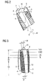
- FIGS. 2 and 3 show part of the tool head 3 of the tapping tool 1 from FIG.
- FIGS. 2 and 3 show part of the tool head 3 of the tapping tool 1 from FIG.
- the tapping tool 1 is designed such that the flutes 9 and the cutting edges 4 to 7 have a left-hand twist with respect to the tool center axis M.
- the helix angle ⁇ of a flute 9 is entered as an example in FIG.
- the helix angle ⁇ of a flute 9 may be in the tapping tool 1 between 2 ° and 15 ° and is given in relation to the central axis M of the tapping tool 1.
- the helix angle ⁇ is about 5 ° to 7 °.
- the helix angle ⁇ is chosen equal in the case of the present embodiment in all flutes 9.
- the tapping tool 1 is configured in such a way that the peeling sections 8 each have a peel angle ⁇ A of between 5 ° and 20 °, preferably approximately 8 ° to 12 ° with respect to the central axis M of the tapping tool 1 have.
- the peeling leading bevel ⁇ A is chosen to be the same for all peeling sections 8 and is likewise indicated with respect to the center axis M of the tapping tool 1 (see FIG.
- the Schwarzlanismeschräge is left skew in the case of the present embodiment in cooperation with a left-tipped flute 9.
- the tapping tool is preferably provided for the production of right-hand threads.
- the peel angle ⁇ is the inclination of the core of the peel angle 8 against the center axis M of the tapping tool 1, which peel angle 8 merges into a flute 9.
- the peel angle inclination ⁇ is approximately 8 ° to 10 °.
- a scarfing section 8 extends over approximately one-fifth to three-quarters of the length of a flute 9, which can be seen from FIGS. 1 to 3.
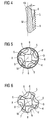
- the tapping tool 1 also has, along its tool head 3, various cutting areas provided with the external thread, which are entered in FIG.
- the so-called gate starting from the end face of the tool head 3, the threads of the external thread are flattened, the flattening of the threads in the first region I starting from the end face of the tool head 3 on the second area II decreases. This results in a conical configuration of the region I of the tapping tool 1.
- the tapping tool 1 in the first region I which substantially corresponds to the region of the Schlanterrorisms 8, six threads, which are more or less flattened on.
- the first region I is adjoined by a second region II of threads of the external thread, wherein the threads arranged in the second region II are full threads, ie threads without flattening of the external thread of the tapping tool 1.
- the threads arranged in the second region II are full threads, ie threads without flattening of the external thread of the tapping tool 1.
- three full threads of the external thread are arranged in the second region II.
- a third region III follows, in which, starting from the second region II, the threads are flattened again in the direction of the tool shank 2 of the tapping tool 1, the flattening increasing starting from the second region II in the direction of the tool shank 2.
- the adjoining the third region III region of the tool head 3 is therefore smaller in the maximum diameter than the second region II in the maximum diameter.
- the threads of the tool head 3 are interrupted by the Schlanuße 8 and flutes 9.
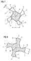
- FIG. 3 To explain the structure of the tapping tool 1, four sections VII to X are further entered in FIG. 3, the sectional views of which are illustrated in FIGS. 7 to 10.
- the sectional views VII to X can be seen on the one hand that in the case of the present embodiment in the tapping tool 1, the rake angle ⁇ P of the peripheral cutting edges 11 of the cutting edges 4 to 7, preferably continuously changed starting from the end face on the tool head 3 in the direction of the tool shank 2 ,
- the rake angle ⁇ P is approximately equal to all peripheral cutting edges 11 of the cutting edges 4 to 7 in a cross section.
- the rake angle ⁇ P which is given with respect to a circumferential cutting edge 12 and a tangent in the cutting direction S to the peripheral cutting edge 12 of one of the peripheral cutting edges 11 of the cutting edges 4 to 7, can be seen from the end face of the tool head 3, which is shown in FIG , change from + 30 ° to -5 ° at the end of a skiving gate 8.
- This last embodiment of the rake angle ⁇ P is not shown in the figures.
- a last small positive rake angle ⁇ P is entered by way of example at the circumferential cutting edge 12 of the cutting edge 5.
- the core diameter d of the tapping tool 1 increases starting from the end face of the tool head 3 in the direction of the tool shank 2. This is evident both from FIG. 7 in which the actual core diameter d and with an enlarged ßerten circle indicated the increasing core diameter d registered is to recognize and from the Figures 8 to 10 and 6, which shows a plan view of the tapping tool 1.
- each cutting edge 4 to 7 also increases, with the cutting width or tooth width Z b of each cutting edge 4 to 7 additionally increasing.
- FIG. 8 and FIG. 10 show by way of example the tooth width Z b for the cutting edge 4.
- the cross-sectional areas of the cutting edges 4 to 7 and the tooth widths Z b of the cutting edges 4 to 7 are approximately the same for all cutting edges 4 to 7 in a cross section.
- tapping tool 1 The embodiment of the tapping tool 1 described above can also be seen from the plan views, as shown in Figures 5 and 6, wherein additionally in Figure 5, the external thread of the cutting 4 to 7 is shown in the drawing, as shown in FIG 6 in comparison to FIG 5 was waived.
- the tapping tool 1 described above is particularly suitable for machining through holes of higher strength steels or for machining through holes at high speed, because of its structure.
- the resulting by the threads of the external thread of the tapping tool 1 in the processing of a through hole chips forward, d. H. deployed out of the through hole.
- For "stray" chips, so shavings that do not move forward, provided with a left twist flutes 9 are provided for the removal of the chips.
- the tapping tool can have less than four cutting edges, but also more than four cutting edges.
- the tapping tool may have three or five cutting edges.
- the cutting edges can be arranged with the same or unequal pitch around the central axis M.
- the details of the helix angle of the flutes, the peel angle bevels and the rake angle relate to the respective circumferential cutting edge of a cutting edge, wherein all cutting edges are configured substantially the same.
- the tool can also have one or more flutes with a right-handed twist, which are associated with a Schlanintroductory or those Schwarzethres, which are skewed to the right or right skew.
- Such a trained tapping tool is preferably provided for the production of left-hand threads.
- angle settings for example for the helix angle, the peel angle bevel, the peel angle tendency and / or the rake angle as described above in connection with the present embodiment are selectable within the scope of the invention.
- tapping tool need not necessarily have three such portions I to III as described above.
- the dimensioning of the tapping tool itself is selected depending on the workpieces to be machined or the through-holes to be processed.
- the thread profile angles are preferably between 50 ° and 70 ° and the thread flank angles between 25 ° and 35 °.
Landscapes
- Engineering & Computer Science (AREA)
- Mechanical Engineering (AREA)
- Milling Processes (AREA)
- Turning (AREA)
- Auxiliary Devices For Machine Tools (AREA)
Abstract
Description
- Die Erfindung betrifft ein Werkzeug für die Bearbeitung eines Werkstücks, welches Werkzeug um eine Werkzeugachse drehbar ist, aufweisend einen Werkzeugschaft und einen Werkzeugkopf. Der Werkzeugkopf weist wenigstens eine Schneide, wenigstens einen Schälanschnitt und wenigstens eine Spannut auf.
- Bei einem derartigen Werkzeug kann es sich beispielsweise um einen Gewindebohrer handeln, wie er in der
DE 83 24 835 U1 beschrieben ist. Der Gewindebohrer aus derDE 83 24 835 U1 weist in seinem Schaftteil drei gleichmäßig über den Umfang verteilt angeordnete achsparallele Schmutznuten auf, zwischen denen Zähne tragende Stege angeordnet sind. Kopfseitig im Anschnittbereich des Gewindebohrers ist dieser konisch ausgebildet durch einen Abschnitt der Spitzen der Zähne. In diesem Bereich sind Schälausschnittnuten angeordnet, die mit ihren rückwärtigen Enden in die gerade verlaufenden Schmutznuten übergehen und zur Stirnseite des Gewindebohrers hin tiefer gerichtet sind. Dadurch werden sich nach vorne verjüngende Stege ausgebildet, die eine Schneidkante tragen. - Derartige Gewindebohrer mit einem Schälanschnitt sind besonders geeignet zum Gewindeschneiden in Durchgangsbohrungen. Dabei werden die Späne in Schnittrichtung ausgebracht, so dass diese aus dem Bohrloch fallen und den Schnittprozess nicht durch einen Spanstau hindern.
- Der Erfindung liegt die Aufgabe zugrunde, ein Werkzeug der eingangs genannten Art derart anzugeben, dass die Schnittleistung des Werkzeugs möglichst gut ist.
- Nach der Erfindung wird diese Aufgabe gelöst durch ein Werkzeug für die Bearbeitung eines Werkstücks, welches Werkzeug um eine Werkzeugachse drehbar ist, aufweisend einen Werkzeugschaft und einen Werkzeugkopf, welcher Werkzeugkopf wenigstens eine Schneide, wenigstens einen der Schneide zugeordneten, sich im Wesentlichen in Richtung der Werkzeugachse erstreckenden Schälanschnitt und wenigstens eine der Schneide zugeordnete, sich im Wesentlichen in Richtung der Werkzeugachse erstreckende Spannut umfasst, wobei die Spannut einen Linksdrall aufweist und der Schälanschnitt linksschräg ist oder wobei die Spannut einen Rechtsdrall aufweist und der Schälanschnitt rechtsschräg ist. Der Schälanschnitt geht dabei in die Spannut über. Es hat sich gezeigt, dass ein Werkzeug mit einer Schneide, einem Schälanschnitt und einer Spannut, die einen Linksdrall umfasst und deren zugeordneter Schälanschnitt linksschräg ist oder die einen Rechtsdrall umfasst und deren Schälanschnitt rechtsschräg ist, gute Schnitteigenschaften aufweist. Insbesondere wenn das Werkzeug eine Gewindebohrwerkzeug ist, wird ein Rechtsgewinde bearbeitet, wenn die Spannut einen Linksdrall umfasst und deren zugeordneter Schälanschnitt linksschräg ist, bzw. wird ein Linksgewinde bearbeitet, wenn die Spannut einen Rechtsdrall umfasst und deren zugeordneter Schälanschnitt rechtsschräg ist.
- Ein derartiges Werkzeug zeigt gute Standleistungen und hat sich insbesondere als vorteilhaft erwiesen bei der Durchgangslochbearbeitung von Stählen mit höherer Festigkeit und zur Bearbeitung von Durchgangslöchern mit Hochgeschwindigkeit, wobei das Werkzeug um seine Werkzeugachse gedreht wird. Beispielsweise kann das Werkzeug zur Bearbeitung von Vergütungsstählen, Nitrierstählen, Warmarbeitsstählen, gehärteten Stählen, Kaltarbeitsstählen, Einsatzstählen und/oder legierten Stählen, z.B. 42CrMo4V mit einer Zugfestigkeit Rm von ca. 1000 N/mm2 oder C45 mit einer Zugfestigkeit Rm von ca. 600 N/mm2, verwendet werden. Bei der Bearbeitung von 42CrMo4V beträgt die Schnittgeschwindigkeit vc ca. 5 bis 50 m/min, bevorzugt 10 m/min, und bei der Bearbeitung von C45 ca. 10 bis 100 m/min, bevorzugt 20 m/min. Das Werkzeug wird also vorzugsweise in einem Schnittgeschwindigkeitsbereich von ca. 5 bis 100 m/min betrieben.
- Mittels des Schälanschnitts werden dabei die beim Schneidprozess entstehenden Späne nach vorne aus einem Durchgangsloch ausgebracht. Für sogenannte "verirrte" Späne, die sich nicht wie erwünscht nach vorne, sondern in Richtung des Werkzeugschaftes bewegen, dient die linksgedrallte Spannut zur axialen Spanabfuhr.
- Nach einer Variante der Erfindung beträgt der Drallwinkel des Linksdralls oder des Rechtsdralls der Spannut zwischen 2° und 15°, vorzugsweise 5° bis 7°, bezogen auf die Werkzeugachse des Werkzeugs.
- Nach Ausführungsformen der Erfindung beträgt die Schälanschnittschräge des Schälanschnitts zwischen 5° und 20°, vorzugsweise 8° bis 12°, und die Schälanschnittneigung des Schälanschnitts zwischen 3° und 15°, vorzugsweise 8° bis 10°. Die Schälanschnittschräge und die Schälanschnittneigung werden ebenfalls auf die Werkzeugachse des Werkzeugs bezogen angegeben. Die Schälanschnittschräge ist in Bezug auf die Werkzeugachse linksschräg oder rechtsschräg.
- Die Schneide des Werkzeugs umfasst eine Umfangsschneide. Der Spanwinkel der Umfangsschneide zum Schälanschnitt bzw. zur Spannut bezogen auf die Tangente an die Schneidkante der Umfangsschneide in Schnittrichtung beträgt zwischen +30° und -5°. Der Spanwinkel kann zwischen unterschiedlichen Ausführungen des Werkzeugs variieren. Nach einer Variante der Erfindung verändert sich der Spanwinkel der Umfangsschneide ausgehend von der Stirnseite am Werkzeugkopf in Richtung auf den Werkzeugschaft. Bei unterschiedlichen Ausführungsformen des Werkzeugs kann der Spanwinkel dabei bezogen auf eine bestimmte Messstelle am Werkzeug variieren. Der Spanwinkel kann sich bei unterschiedlichen Ausführungsformen des Werkzeugs also ausgehend von der Stirnseite am Werkzeugkopf in Richtung auf den Werkzeugschaft unterschiedlich verändern. Bevorzugt verändert sich der Spanwinkel kontinuierlich in dem angegebenen Bereich von +30° und -5° von der Stirnseite des Werkzeugkopfs bis zum Ende des Schälanschnitts, wobei sowohl der Anfangswert als auch der Endwert variabel sind. Der Spanwinkel kann sich also ändern, muss sich aber nicht notwendigerweise ändern. Am Ende des Schälanschnitts weist der Spanwinkel nach einer Variante der Erfindung einen Endwert zwischen +30° und -5°, vorzugsweise zwischen +15° und -5° auf.
- Die Länge des Schälanschnitts des Werkzeugs erstreckt sich zwischen ca. einem Fünftel (1/5) bis zu drei Vierteln (3/4) der Länge der Spannut, d. h. würde man die Spannut von der Stirnseite des Werkzeugs bis zu ihrem Ende am Werkzeugkopf messen, so erstreckt sich der Schälanschnitt über ca. ein Fünftel bis zu Dreivierteln der Länge der Spannut ausgehend von der Stirnseite des Werkzeugs, an der der Schälanschnitt beginnt.
- Nach Ausführungsformen der Erfindung nimmt der Seelendurchmesser des Werkzeugs, ausgehend von der Stirnseite des Werkzeugkopfs in Richtung auf den Werkzeugschaft zu. Dabei vergrößert sich auch die Querschnittsfläche der Schneide, ausgehend von der Stirnseite des Werkzeugkopfes in Richtung auf den Werkzeugschaft, wobei bevorzugt auch die Zahnbreite der Schneide zunimmt.
- Varianten der Erfindung sehen vor, dass das Werkzeug mehrere Schneiden, beispielsweise drei, vier, fünf oder mehr Schneiden aufweist und dass es sich bei dem Werkzeug um ein Gewindebohrwerkzeug handelt, welches ein schraubenlinienförmig verlaufendes Außengewinde umfasst. Das Außengewinde ist dabei an den Schneiden bzw. den Umfangsschneiden der Schneiden angeordnet, welche durch die Schälanschnitte und Spannuten voneinander getrennt sind. Weist das Werkzeug eine Spannut mit einem Linksdrall und einen Schälanschnitt, der linksschräg ist, auf, so ist dieses Werkzeug bevorzugt zur Fertigung von Rechtsgewinden vorgesehen. Weist das Werkzeug hingegen eine Spannut mit einem Rechtsdrall und einen Schälanschnitt, der rechtsschräg ist, auf, so ist diese Werkzeug bevorzugt zur Fertigung von Linksgewinden vorgesehen.
- Nach einer Variante der Erfindung sind ausgehend von der Stirnseite des Werkzeugkopfes in einem ersten Bereich des Werkzeugkopfes, dem Anschnitt oder Anschnittbereich, die Gewindegänge des Außengewindes abgeflacht und in einem sich an den ersten Bereich anschließenden zweiten Bereich des Werkzeugkopfes volle Gewindegänge vorhanden, worunter ein Gewindegang ohne Abflachung verstanden wird, der durchaus durch Schälanschnitte oder Spannuten unterbrochen sein kann. Die Abflachung der Gewindegänge in dem ersten Bereich nimmt dabei ausgehend von der Stirnseite des Werkzeugkopfes auf den zweiten Bereich ab.
- Nach einer Ausführungsform der Erfindung weist das Werkzeug einen sich an den zweiten Bereich anschließenden dritten Bereich von Gewindegängen des Werkzeugkopfes auf, in dem die Gewindegänge ebenfalls abgeflacht sind. Die Abflachung der Gewindegänge in dem dritten Bereich nimmt dabei ausgehend von dem zweiten Bereich in Richtung auf den Werkzeugschaft zu.
- Bevorzugt sind in dem zweiten Bereich zwischen einem und zehn volle Gewindegänge vorhanden. Der zweite Bereich der Gewindegänge beginnt dabei ungefähr im Bereich des Endes des Schälanschnitts, in dem bevorzugt drei bis neun Gewindegänge, die, wie bereits erwähnt, abgeflacht sind, vorhanden sind. Der zweite Bereich schließt sich an den Anschnitt an.
- Ein Ausführungsbeispiel der Erfindung ist in den beigefügten schematischen Zeichnungen dargestellt. Es zeigen:
- FIG 1
- in einer perspektivischen Darstellung ein Gewindebohrwerkzeug nach der Erfindung,
- FIG 2
- in einer perspektivischen Darstellung einen Abschnitt des Gewindebohrwerkzeuges aus FIG 1,
- FIG 3
- in einer Seitenansicht einen Abschnitt des Gewindebohrwerkzeuges aus FIG 1,
- FIG 4
- in einer geschnittenen Darstellung einen Teil des Gewindebohrwerkzeugs aus FIG 1,
- FIG 5 und FIG 6
- Draufsichten auf das Gewindebohrwerkzeug aus FIG 1 und
- FIG 7 bis FIG 10
- verschiedene Querschnittsdarstellungen des Gewindebohrwerkzeugs aus FIG 1 gemäß der in FIG 3 eingetragenen Schnittlinien.
- In FIG 1 ist ein erfindungsgemäßes Werkzeug für die spanabhebende Bearbeitung eines Werkstücks dargestellt, bei dem es sich im Falle des vorliegenden Ausführungsbeispiels um ein Gewindebohrwerkzeug 1 handelt. Das Gewindebohrwerkzeug 1 umfasst einen Werkzeugschaft 2 zum Einspannen in eine Werkzeugmaschine und einen Werkzeugkopf 3. Der Werkzeugschaft 2 geht über eine Phase P in den Werkzeugkopf 3 über. Das Gewindebohrwerkzeug 1 umfasst eine Werkzeugachse in Form einer Mittelachse M, um die das Gewindebohrwerkzeug 1 drehbar ist.
- Im Falle des vorliegenden Ausführungsbeispiels sind am Werkzeugkopf 3 des Gewindebohrwerkzeugs 1 vier Schneiden 4 bis 7 um die Mittelachse M angeordnet, die mit einem Außengewinde versehen sind, das in FIG 1 jedoch nicht eingezeichnet ist. Das Außengewinde der Schneiden 4 bis 7, welches sich schraubenlinienförmig verlaufend entlang des Werkzeugkopfes 3 erstreckt, ist in den FIG 2 und 3 zu erkennen, die einen Teil des Werkzeugkopfes 3 des Gewindebohrwerkzeuges 1 aus FIG 1 zeigen. Wie insbesondere den FIG 1 und 2 entnommen werden kann, ist zwischen zwei aufeinanderfolgenden Schneiden der Schneiden 4 bis 7 stirnseitig des Werkzeugkopfes 3 jeweils ein Schälanschnitt 8 und sich an den Schälanschnitt 8 anschließend eine Spannut 9 vorhanden. An der Stirnseite weist das Gewindebohrwerkzeug 1 im Falle des vorliegenden Ausführungsbeispiels im Übrigen eine Zentrierspitze 10 auf.
- Das Gewindebohrwerkzeug 1 ist erfindungsgemäß derart ausgebildet, dass die Spannuten 9 bzw. die Schneiden 4 bis 7 einen Linksdrall in Bezug auf die Werkzeugmittelachse M aufweisen. Der Drallwinkel γ einer Spannut 9 ist in FIG 3 exemplarisch eingetragen. Der Drallwinkel γ einer Spannut 9 kann bei dem Gewindebohrwerkzeug 1 zwischen 2° und 15° betragen und wird in Bezug auf die Mittelachse M des Gewindebohrwerkzeugs 1 angegeben. Bevorzugt beträgt der Drallwinkel γ ca. 5° bis 7°. Der Drallwinkel γ ist im Falle des vorliegenden Ausführungsbeispiels bei allen Spannuten 9 gleich gewählt.
- Des Weiteren ist das Gewindebohrwerkzeug 1 im Falle des vorliegenden Ausführungsbeispiels derart ausgestaltet, dass die Schälanschnitte 8 jeweils eine Schälanschnittschräge bzw. einen Schälanschnittwinkel γA zwischen 5° und 20°, bevorzugt ca. 8° bis 12° in Bezug auf die Mittelachse M des Gewindebohrwerkzeugs 1 aufweisen. Die Schälanschnittschräge γA ist im Falle des vorliegenden Ausführungsbeispiels bei allen Schälanschnitten 8 gleich gewählt und wird ebenfalls in Bezug auf die Mittelachse M des Gewindebohrwerkzeugs 1 angegeben (vgl. FIG 3). Die Schälanschnittschräge ist im Falle des vorliegenden Ausführungsbeispiels linksschräg in Zusammenwirkung mit einer linksgedrallten Spannut 9. Das Gewindebohrwerkzeug ist bevorzugt zur Fertigung von Rechtsgewinden vorgesehen.
- Die Schälanschnittneigung λ eines jeden der Schälanschnitte 8 beträgt zwischen 3° und 15° bezogen auf die Mittelachse M des Gewindebohrwerkzeugs 1. Für einen Ausschnitt eines Schnittes durch das Gewindebohrwerkzeug 1 aus FIG 1 ist die Schälanschnittneigung λ eines Schälanschnitts 8 in Bezug auf die Mittelachse M in FIG 4 exemplarisch dargestellt. Bei der Schälanschnittneigung λ handelt es sich dabei um die Neigung der Seele des Schälanschnitts 8 gegen die Mittelachse M des Gewindebohrwerkzeugs 1, welcher Schälanschnitt 8 in eine Spannut 9 übergeht. Im Falle des vorliegenden Ausführungsbeispiels beträgt die Schälanschnittneigung λ ca. 8° bis 10°.
- Bevorzugt erstreckt sich ein Schälanschnitt 8 über ca. ein Fünftel bis zu drei Vierteln der Länge einer Spannut 9, was aus den FIG 1 bis 3 zu erkennen ist.
- Das Gewindebohrwerkzeug 1 weist im Falle des vorliegenden Ausführungsbeispiels darüber hinaus längs seines Werkzeugkopfes 3 verschiedene mit dem Außengewinde versehene Schnittbereiche auf, die in FIG 3 eingetragen sind. In dem ersten mit I gekennzeichneten Schnittbereich des Gewindebohrwerkzeugs 1, dem sogenannten Anschnitt, sind ausgehend von der Stirnseite des Werkzeugkopfes 3 die Gewindegänge des Außengewindes abgeflacht, wobei die Abflachung der Gewindegänge in dem ersten Bereich I ausgehend von der Stirnseite des Werkzeugkopfes 3 auf den zweiten Bereich II zu abnimmt. Dadurch ergibt sich eine konische Ausgestaltung des Bereichs I des Gewindebohrwerkzeugs 1. Im Falle des vorliegenden Ausführungsbeispiels weist das Gewindebohrwerkzeug 1 in dem ersten Bereich I, der im Wesentlichen dem Bereich des Schälanschnitts 8 entspricht, sechs Gewindegänge, die mehr oder weniger abgeflacht sind, auf.
- An den ersten Bereich I schließt sich ein zweiter Bereich II von Gewindegängen des Außengewindes an, wobei die in dem zweiten Bereich II angeordneten Gewindegänge volle Gewindegänge, also Gewindegänge ohne Abflachung des Außengewindes des Gewindebohrwerkzeugs 1 sind. Im Falle des vorliegenden Ausführungsbeispieles sind im zweiten Bereich II drei volle Gewindegänge des Außengewindes angeordnet. An den zweiten Bereich II schließt sich schließlich ein dritter Bereich III an, in dem ausgehend von dem zweiten Bereich II die Gewindegänge in Richtung auf den Werkzeugschaft 2 des Gewindebohrwerkzeugs 1 zu wieder abgeflacht sind, wobei die Abflachung ausgehend von dem zweiten Bereich II in Richtung auf den Werkzeugschaft 2 zunimmt. Der sich an den dritten Bereich III anschließende Bereich des Werkzeugkopfes 3 ist demnach im maximalen Durchmesser kleiner als der zweite Bereich II im maximalen Durchmesser.
- Wie insbesondere den Figuren 1 bis 3 entnommen werden kann, sind die Gewindegänge des Werkzeugkopfes 3 durch die Schälanschnitte 8 und Spannuten 9 unterbrochen.
- Zur Erläuterung des Aufbaus des Gewindebohrwerkzeugs 1 sind in FIG 3 des Weiteren vier Schnitte VII bis X eingetragen, deren Schnittansichten in den FIG 7 bis 10 dargestellt sind. Den Schnittansichten VII bis X kann zum einen entnommen werden, dass sich im Falle des vorliegenden Ausführungsbeispiels bei dem Gewindebohrwerkzeug 1 der Spanwinkel γP der Umfangsschneiden 11 der Schneiden 4 bis 7 ausgehend von der Stirnseite am Werkzeugkopf 3 in Richtung auf den Werkzeugschaft 2 bevorzugt kontinuierlich verändert. Der Spanwinkel γP ist dabei an allen Umfangsschneiden 11 der Schneiden 4 bis 7 in einem Querschnitt ungefähr gleich. Der Spanwinkel γP, welcher jeweils bezüglich einer Umfangsschneidkante 12 bzw. einer Tangente in Schnittrichtung S an die Umfangsschneidkante 12 einer der Umfangsschneiden 11 der Schneiden 4 bis 7 angegeben wird, kann sich ausgehend von der Stirnseite des Werkzeugkopfes 3, was in FIG 7 dargestellt ist, von +30° bis zu -5° am Ende eines Schälanschnitts 8 verändern. Diese letzte Ausgestaltung des Spanwinkels γP ist in den Figuren aber nicht dargestellt. In FIG 10 ist für das vorliegenden Ausführungsbeispiel ein letzter kleiner positiver Spanwinkel γP exemplarisch an der Umfangsschneidkante 12 der Schneide 5 eingetragen.
- Wie aus den FIG 7 bis 10 zu erkennen, vergrößert sich der Seelendurchmesser d des Gewindebohrwerkzeugs 1 ausgehend von der Stirnseite des Werkzeugkopfes 3 in Richtung auf den Werkzeugschaft 2. Dies ist sowohl aus FIG 7, in welcher der aktuelle Seelendurchmesser d und mit einem vergrö-ßerten Kreis angedeutet der zunehmende Seelendurchmesser d eingetragen ist, zu erkennen sowie aus den FIG 8 bis 10 als auch aus FIG 6, welche eine Draufsicht auf das Gewindebohrwerkzeug 1 zeigt.
- Ausgehend von der Stirnseite des Werkzeugkopfes 3 in Richtung auf den Werkzeugschaft 2 vergrößert sich auch jeweils die Querschnittsfläche einer jeden Schneide 4 bis 7, wobei zusätzlich die Schneidenbreite bzw. Zahnbreite Zb einer jeden Schneide 4 bis 7 zunimmt. In den FIG 8 und FIG 10 ist exemplarisch die Zahnbreite Zb für die Schneide 4 eingetragen. Die Querschnittsflächen der Schneiden 4 bis 7 und die Zahnbreiten Zb der Schneiden 4 bis 7 sind dabei für allen Schneiden 4 bis 7 in einem Querschnitt ungefähr gleich.
- Die vorstehend beschriebene Ausgestaltung des Gewindebohrwerkzeugs 1 ist auch aus den Draufsichten, wie sie in den FIG 5 und 6 dargestellt sind, erkennbar, wobei zusätzlich in FIG 5 das Außengewinde der Schneiden 4 bis 7 zeichnerisch dargestellt ist, worauf in FIG 6 im Vergleich zu FIG 5 verzichtet wurde.
- Das vorstehend beschriebene Gewindebohrwerkzeug 1 eignet sich aufgrund seines Aufbaus besonders für die Bearbeitung von Durchgangslöchern von Stählen mit höherer Festigkeit bzw. zur Bearbeitung von Durchgangslöchern mit Hochgeschwindigkeit. Dabei werden die durch die Gewindegänge des Außengewindes des Gewindebohrwerkzeugs 1 bei der Bearbeitung eines Durchgangsloches entstehenden Späne nach vorne, d. h. aus dem Durchgangsloch heraus ausgebracht. Für "verirrte" Späne, also Späne, die sich nicht nach vorne bewegen, sind die mit einem Linksdrall versehenen Spannuten 9 zur Abführung der Späne vorgesehen.
- Der vorstehend beschriebene Aufbau eines erfindungsgemäßen Werkzeugs, insbesondere eines erfindungsgemäßen Gewindebohrwerkzeugs ist nur exemplarisch zu verstehen und kann im Rahmen der Erfindung auch anders ausgeführt sein. So kann das Gewindebohrwerkzeug weniger als vier Schneiden, aber auch mehr als vier Schneiden aufweisen. Insbesondere kann das Gewindebohrwerkzeug drei oder fünf Schneiden aufweisen. Die Schneiden können mit gleicher oder mit ungleicher Teilung um die Mittelachse M angeordnet sein. Die Angaben des Drallwinkels der Spannuten, der Schälanschnittschrägen und der Spanwinkel beziehen sich dabei auf die jeweilige Umfangsschneidkante einer Schneide, wobei alle Schneiden im Wesentlichen gleich ausgestaltet sind.
- Im Unterschied zu dem beschriebenen Ausführungsbeispiel kann das Werkzeug auch eine oder mehrere Spannuten mit einem Rechtsdrall aufweisen, der ein Schälanschnitt bzw. denen Schälanschnitte zugeordnet sind, der rechtsschräg bzw. die rechtsschräg ausgebildet sind. Ein derart ausgebildetes Gewindebohrwerkzeug ist bevorzugt zur Fertigung von Linksgewinden vorgesehen.
- Im Übrigen sind andere Winkeleinstellungen, beispielsweise für den Drallwinkel, die Schälanschnittschräge, die Schälanschnittneigung und/oder den Spanwinkel als vorstehend im Zusammenhang mit dem vorliegenden Ausführungsbeispiels beschrieben im Rahmen der Erfindung wählbar.
- Gleiches gilt für die Anzahl der Gewindegänge in den Bereichen I bis III sowie für die Wahl der Länge des Schälanschnitts. Das Gewindebohrwerkzeug muss auch nicht notwendigerweise, wie vorstehend beschrieben, drei derartige Bereiche I bis III aufweisen.
- Die Bemaßung des Gewindebohrwerkzeugs an sich wird dabei jeweils in Abhängigkeit von dem zu bearbeitenden Werkstücken bzw. den zu bearbeitenden Durchgangsbohrlöchern gewählt. Bevorzugt betragen die Gewindeprofilwinkel dabei zwischen 50° und 70° und die Gewindeflankenwinkel zwischen 25° und 35°.
-
- 1
- Gewindebohrwerkzeug
- 2
- Werkzeugschaft
- 3
- Werkzeugkopf
- 4 bis 7
- Schneiden
- 8
- Schälanschnitt
- 9
- Spannut
- 10
- Zentrierspitze
- 11
- Umfangsschneide
- 12
- Umfangsschneidkante
- γ
- Drallwinkel
- γA
- Schälanschnittschräge
- λ
- Schälanschnittneigung
- γP
- Spanwinkel
- d
- Seelendurchmesser
- Zb
- Zahnbreite
- M
- Mittelachse
- S
- Schnittrichtung
- P
- Phase
- D
- Drehrichtung
- I bis III
- Bereiche
- VII bis X
- Schnitte
Claims (10)
- Werkzeug für die Bearbeitung eines Werkstücks, welches Werkzeug um eine Werkzeugachse (M) drehbar ist, aufweisend
einen Werkzeugschaft (2) und einen Werkzeugkopf (3),
welcher Werkzeugkopf (3) wenigstens eine Schneide (4 bis 7), wenigstens einen der Schneide (4 bis 7) zugeordneten Schälanschnitt (8) und wenigstens eine der Schneide (4 bis 7) zugeordnete Spannut (9) umfasst,
wobei die Spannut (9) einen Linksdrall aufweist und der Schälanschnitt (8) linksschräg ist oder wobei die Spannut (9) einen Rechtsdrall aufweist und der Schälanschnitt (8) rechtsschräg ist. - Werkzeug nach Anspruch 1, bei dem der Drallwinkel (γ) des Linksdralls oder des Rechtsdralls der Spannut (9) zwischen 2° und 15° beträgt.
- Werkzeug nach Anspruch 1 oder 2, bei dem der Schälanschnitt (8) eine Schälanschnittschräge (γA) zwischen 5° und 20° linksschräg oder rechtsschräg aufweist und/oder bei dem der Schälanschnitt (8) eine Schälanschnittneigung (λ) zwischen 3° und 15° aufweist.
- Werkzeug nach einem der Ansprüche 1 bis 4, bei dem die Schneide (4 bis 7) eine Umfangsschneide (11) umfasst, welche einen Spanwinkel (γP) aufweist, welcher zwischen +30° und -5° beträgt und/oder welcher sich ausgehend von der Stirnseite am Werkzeugkopf (3) in Richtung auf den Werkzeugschaft (2), vorzugsweise kontinuierlich, verändert.
- Werkzeug nach Anspruch 4, bei dem der Spanwinkel (γP) am Ende des Schälanschnitts (8) zwischen +30° und -5° beträgt.
- Werkzeug nach einem der Ansprüche 1 bis 5, bei dem sich der Schälanschnitt (8) zwischen ca. einem Fünftel (1 /5) bis zu drei Vierteln (3/4) der Länge der Spannut (9) erstreckt
und/oder bei dem der Seelendurchmesser (d) ausgehend von der Stirnseite des Werkzeugkopfes (3) in Richtung auf den Werkzeugschaft (2) zunimmt
und/oder bei dem sich die Querschnittsfläche der Schneide (4 bis 7) ausgehend von der Stirnseite des Werkzeugkopfes (3) in Richtung auf den Werkzeugschaft (2) vergrößert. - Werkzeug nach einem der Ansprüche 1 bis 6, welches mehrere Schneiden (4 bis 7) aufweist und/oder welches ein Gewindebohrwerkzeug (1) ist und vorzugsweise ein schraubenlinienförmig verlaufendes Außengewinde aufweist.
- Werkzeug nach Anspruch 7, bei dem ausgehend von der Stirnseite des Werkzeugkopfes (3) in einem ersten Bereich (I) die Gewindegänge des Außengewindes abgeflacht sind und in einem sich an den ersten Bereich (I) anschließenden zweiten Bereiche (II) volle Gewindegänge vorhanden sind, wobei vorzugsweise die Abflachung der Gewindegänge in dem ersten Bereich (I) ausgehend von der Stirnseite des Werkzeugkopfes (3) auf den zweiten Bereich (II) abnimmt.
- Werkzeug nach Anspruch 8, welches einen sich an den zweiten Bereich (II) anschließenden dritten Bereich (III) von Gewindegängen aufweist, in dem die Gewindegänge abgeflacht sind, wobei vorzugsweise die Abflachung der Gewindegänge in dem dritten Bereich (III) ausgehend von dem zweiten Bereich (II) in Richtung auf den Werkzeugschaft (2) zunimmt.
- Werkzeug nach Anspruch 8 oder Anspruch 9, bei dem in dem zweiten Bereich (II) zwischen einem und zehn volle Gewindegänge vorhanden sind und/oder bei dem im Bereich des Endes des Schälanschnitts (8) der zweite Bereich (II) der Gewindegänge beginnt und/oder bei dem im Bereich des Schälanschnitts (8) drei bis neun Gewindegänge vorhanden sind.
Priority Applications (1)
| Application Number | Priority Date | Filing Date | Title |
|---|---|---|---|
| PL07014752T PL1902805T3 (pl) | 2006-09-19 | 2007-07-27 | Narzędzie do obróbki przedmiotu obrabianego |
Applications Claiming Priority (1)
| Application Number | Priority Date | Filing Date | Title |
|---|---|---|---|
| DE102006044575A DE102006044575A1 (de) | 2006-09-19 | 2006-09-19 | Werkzeug für die Bearbeitung eines Werkstücks |
Publications (3)
| Publication Number | Publication Date |
|---|---|
| EP1902805A2 true EP1902805A2 (de) | 2008-03-26 |
| EP1902805A3 EP1902805A3 (de) | 2009-10-21 |
| EP1902805B1 EP1902805B1 (de) | 2011-03-09 |
Family
ID=38829640
Family Applications (1)
| Application Number | Title | Priority Date | Filing Date |
|---|---|---|---|
| EP07014752A Active EP1902805B1 (de) | 2006-09-19 | 2007-07-27 | Werkzeug für die Bearbeitung eines Werkstücks |
Country Status (6)
| Country | Link |
|---|---|
| US (1) | US8272817B2 (de) |
| EP (1) | EP1902805B1 (de) |
| AT (1) | ATE500916T1 (de) |
| DE (2) | DE102006044575A1 (de) |
| ES (1) | ES2361728T3 (de) |
| PL (1) | PL1902805T3 (de) |
Cited By (1)
| Publication number | Priority date | Publication date | Assignee | Title |
|---|---|---|---|---|
| EP2346637A2 (de) * | 2008-10-14 | 2011-07-27 | Kennametal Inc. | Gewindeschneider und herstellungsverfahren dafür |
Families Citing this family (10)
| Publication number | Priority date | Publication date | Assignee | Title |
|---|---|---|---|---|
| US8087856B2 (en) * | 2006-09-22 | 2012-01-03 | Reed Gary J | Double helix thread cutting tap |
| US7665934B2 (en) * | 2006-10-18 | 2010-02-23 | Kennametal Inc. | Cutting tap and method of making a cutting tap |
| IL211236A0 (en) * | 2011-02-15 | 2011-04-28 | Vladimir Volokh | Rotary cutter |
| US20150016911A1 (en) * | 2012-03-09 | 2015-01-15 | Osg Corporation | Spiral tap |
| JP5816368B2 (ja) * | 2012-07-17 | 2015-11-18 | オーエスジー株式会社 | スパイラルタップ |
| US20160039024A1 (en) * | 2013-04-08 | 2016-02-11 | Juko Seiki Co., Ltd. | Cutting tool for processing nut of sliding screw device and method for processing nut of sliding screw device |
| DK3145666T3 (en) * | 2014-05-20 | 2018-07-16 | Natalino Capone | DRILLING TOOLS |
| US9839984B2 (en) * | 2014-08-14 | 2017-12-12 | Kennametal Inc. | Method of making a cutting tap with a correction grind |
| WO2022032178A1 (en) | 2020-08-06 | 2022-02-10 | Mate Precision Technologies Inc. | Vise assembly |
| US11878381B2 (en) | 2020-08-06 | 2024-01-23 | Mate Precision Technologies Inc. | Tooling base assembly |
Citations (9)
| Publication number | Priority date | Publication date | Assignee | Title |
|---|---|---|---|---|
| DE416709C (de) * | 1923-07-22 | 1925-07-23 | Gustav Kuntze Dipl Ing | Gewindebohrer zum Schneiden von kegeligem Gewinde |
| US2202236A (en) * | 1938-04-27 | 1940-05-28 | Greenfield Tap & Die Corp | Tap |
| GB1090875A (en) * | 1964-08-16 | 1967-11-15 | Firth Brown Tools Ltd | Improvements in screw-cutting taps |
| DE2331927A1 (de) * | 1973-06-22 | 1975-01-23 | Ishihashi Seiko Higashioosaka | Werkzeug zum schneiden von innengewinde |
| FR2350163A1 (fr) * | 1976-05-03 | 1977-12-02 | Glimpel Emuge Werk | Taraud a entree progressive |
| DE8324835U1 (de) * | 1983-08-30 | 1983-12-08 | Wilhelm Fette Gmbh, 2053 Schwarzenbek | Gewindebohrer |
| FR2701226A1 (fr) * | 1993-02-08 | 1994-08-12 | Rineau Freres Outillage Armor | Taraud à goujures hélicoïdales évolutives. |
| RU2021085C1 (ru) * | 1991-06-17 | 1994-10-15 | Акционерное общество "Автонормаль" | Метчик для нарезания точных резьб |
| JP2001353623A (ja) * | 2000-06-12 | 2001-12-25 | Osg Corp | スパイラルタップおよびその製造方法 |
Family Cites Families (9)
| Publication number | Priority date | Publication date | Assignee | Title |
|---|---|---|---|---|
| US3328814A (en) * | 1964-12-07 | 1967-07-04 | Nat Twist Drill & Tool Company | Tap |
| US4708542A (en) * | 1985-04-19 | 1987-11-24 | Greenfield Industries, Inc. | Threading tap |
| JPH01171725A (ja) * | 1987-12-23 | 1989-07-06 | O S G Kk | チップカーラ付ねじれ溝タップ |
| US5562371A (en) * | 1995-06-07 | 1996-10-08 | Lock-N-Stitch International | Tap with a non-cutting pilot |
| US6012882A (en) * | 1995-09-12 | 2000-01-11 | Turchan; Manuel C. | Combined hole making, threading, and chamfering tool with staggered thread cutting teeth |
| US5842924A (en) * | 1997-02-25 | 1998-12-01 | Manos; Mark R. | Thread repairing tool |
| SE518461C2 (sv) * | 2001-02-21 | 2002-10-15 | Henrik Hansson | Benskruv, sätt för att framställa dess gängor och borr för att borra hål för detsamma |
| SE522664C2 (sv) * | 2001-04-30 | 2004-02-24 | Sandvik Ab | Skärande gängtapp och förfarande för dess tillverkning |
| US7144208B2 (en) * | 2004-06-07 | 2006-12-05 | Kennametal Inc. | Low torque tap |
-
2006
- 2006-09-19 DE DE102006044575A patent/DE102006044575A1/de not_active Withdrawn
-
2007
- 2007-07-27 DE DE502007006649T patent/DE502007006649D1/de active Active
- 2007-07-27 PL PL07014752T patent/PL1902805T3/pl unknown
- 2007-07-27 EP EP07014752A patent/EP1902805B1/de active Active
- 2007-07-27 ES ES07014752T patent/ES2361728T3/es active Active
- 2007-07-27 AT AT07014752T patent/ATE500916T1/de active
- 2007-09-10 US US11/852,867 patent/US8272817B2/en active Active
Patent Citations (9)
| Publication number | Priority date | Publication date | Assignee | Title |
|---|---|---|---|---|
| DE416709C (de) * | 1923-07-22 | 1925-07-23 | Gustav Kuntze Dipl Ing | Gewindebohrer zum Schneiden von kegeligem Gewinde |
| US2202236A (en) * | 1938-04-27 | 1940-05-28 | Greenfield Tap & Die Corp | Tap |
| GB1090875A (en) * | 1964-08-16 | 1967-11-15 | Firth Brown Tools Ltd | Improvements in screw-cutting taps |
| DE2331927A1 (de) * | 1973-06-22 | 1975-01-23 | Ishihashi Seiko Higashioosaka | Werkzeug zum schneiden von innengewinde |
| FR2350163A1 (fr) * | 1976-05-03 | 1977-12-02 | Glimpel Emuge Werk | Taraud a entree progressive |
| DE8324835U1 (de) * | 1983-08-30 | 1983-12-08 | Wilhelm Fette Gmbh, 2053 Schwarzenbek | Gewindebohrer |
| RU2021085C1 (ru) * | 1991-06-17 | 1994-10-15 | Акционерное общество "Автонормаль" | Метчик для нарезания точных резьб |
| FR2701226A1 (fr) * | 1993-02-08 | 1994-08-12 | Rineau Freres Outillage Armor | Taraud à goujures hélicoïdales évolutives. |
| JP2001353623A (ja) * | 2000-06-12 | 2001-12-25 | Osg Corp | スパイラルタップおよびその製造方法 |
Cited By (2)
| Publication number | Priority date | Publication date | Assignee | Title |
|---|---|---|---|---|
| EP2346637A2 (de) * | 2008-10-14 | 2011-07-27 | Kennametal Inc. | Gewindeschneider und herstellungsverfahren dafür |
| EP2346637A4 (de) * | 2008-10-14 | 2013-06-05 | Kennametal Inc | Gewindeschneider und herstellungsverfahren dafür |
Also Published As
| Publication number | Publication date |
|---|---|
| US8272817B2 (en) | 2012-09-25 |
| DE102006044575A1 (de) | 2008-03-27 |
| PL1902805T3 (pl) | 2011-08-31 |
| ATE500916T1 (de) | 2011-03-15 |
| EP1902805A3 (de) | 2009-10-21 |
| ES2361728T3 (es) | 2011-06-21 |
| EP1902805B1 (de) | 2011-03-09 |
| DE502007006649D1 (de) | 2011-04-21 |
| US20080069653A1 (en) | 2008-03-20 |
Similar Documents
| Publication | Publication Date | Title |
|---|---|---|
| EP1902805B1 (de) | Werkzeug für die Bearbeitung eines Werkstücks | |
| DE112007003489B4 (de) | Spiralgewindebohrer | |
| DE69729467T2 (de) | Kaltformgewindebohrer mit inner diameter feinbearbeitungseinsatz und dessen herstellungsmethode | |
| EP2229257B1 (de) | Gewindebohrer und verfahren zur herstellung eines gewindebohrers | |
| DE102010006796B4 (de) | Verfahren zur Herstellung eines Bohrers, sowie Bohrer | |
| DE102006026853A1 (de) | Spanabhebendes Werkzeug | |
| DE3706282A1 (de) | Umlaufendes schneidwerkzeug | |
| DE102014108219A1 (de) | Rotationswerkzeug sowie Verfahren zur Herstellung eines Rotationswerkzeugs | |
| EP2454043B1 (de) | Bohrer | |
| EP1864736A2 (de) | Gewindeerzeugungswerkzeug mit Kantenübergang | |
| EP2929966B1 (de) | Vollfräswerkzeug zur rotierenden Materialbearbeitung | |
| EP2848343A1 (de) | Fräser mit Kordel aus einem speziellen Zahnprofil | |
| DE1575120A1 (de) | Selbstschneidende Schraube | |
| DE102007034087A1 (de) | Fräserwerkzeug | |
| DE102006032005B4 (de) | Werkzeug mit sich veränderndem Nutdrallwinkel | |
| DE112006004174T5 (de) | Spiralnut-Gewindeschneider | |
| DE202016106331U1 (de) | Gewindewerkzeuge mit Fluidkanälen | |
| DE1953183C3 (de) | Selbstbohrende Schneidschraube | |
| DE112008004051T5 (de) | Spiralgewindebohrer | |
| DE102019218421A1 (de) | Holzbohrer | |
| DE102010025148A1 (de) | Spanabhebendes Werkzeug | |
| EP1958589A1 (de) | Dentalfraeser | |
| EP2915613B1 (de) | Querlochsenker | |
| DE2331927A1 (de) | Werkzeug zum schneiden von innengewinde | |
| DE102018115624A1 (de) | Stufenbohrer |
Legal Events
| Date | Code | Title | Description |
|---|---|---|---|
| PUAI | Public reference made under article 153(3) epc to a published international application that has entered the european phase |
Free format text: ORIGINAL CODE: 0009012 |
|
| AK | Designated contracting states |
Kind code of ref document: A2 Designated state(s): AT BE BG CH CY CZ DE DK EE ES FI FR GB GR HU IE IS IT LI LT LU LV MC MT NL PL PT RO SE SI SK TR |
|
| AX | Request for extension of the european patent |
Extension state: AL BA HR MK YU |
|
| PUAL | Search report despatched |
Free format text: ORIGINAL CODE: 0009013 |
|
| AK | Designated contracting states |
Kind code of ref document: A3 Designated state(s): AT BE BG CH CY CZ DE DK EE ES FI FR GB GR HU IE IS IT LI LT LU LV MC MT NL PL PT RO SE SI SK TR |
|
| AX | Request for extension of the european patent |
Extension state: AL BA HR MK RS |
|
| AKX | Designation fees paid | ||
| 17P | Request for examination filed |
Effective date: 20100421 |
|
| RBV | Designated contracting states (corrected) |
Designated state(s): AT BE BG CH CY CZ DE DK EE ES FI FR GB GR HU IE IS IT LI LT LU LV MC MT NL PL PT RO SE SI SK TR |
|
| GRAP | Despatch of communication of intention to grant a patent |
Free format text: ORIGINAL CODE: EPIDOSNIGR1 |
|
| RIC1 | Information provided on ipc code assigned before grant |
Ipc: B23G 5/06 20060101AFI20100909BHEP |
|
| GRAS | Grant fee paid |
Free format text: ORIGINAL CODE: EPIDOSNIGR3 |
|
| GRAA | (expected) grant |
Free format text: ORIGINAL CODE: 0009210 |
|
| AK | Designated contracting states |
Kind code of ref document: B1 Designated state(s): AT BE BG CH CY CZ DE DK EE ES FI FR GB GR HU IE IS IT LI LT LU LV MC MT NL PL PT RO SE SI SK TR |
|
| REG | Reference to a national code |
Ref country code: GB Ref legal event code: FG4D Free format text: NOT ENGLISH |
|
| REG | Reference to a national code |
Ref country code: CH Ref legal event code: EP |
|
| REG | Reference to a national code |
Ref country code: IE Ref legal event code: FG4D Free format text: LANGUAGE OF EP DOCUMENT: GERMAN |
|
| REF | Corresponds to: |
Ref document number: 502007006649 Country of ref document: DE Date of ref document: 20110421 Kind code of ref document: P |
|
| REG | Reference to a national code |
Ref country code: DE Ref legal event code: R096 Ref document number: 502007006649 Country of ref document: DE Effective date: 20110421 |
|
| REG | Reference to a national code |
Ref country code: CH Ref legal event code: NV Representative=s name: FIAMMENGHI-FIAMMENGHI |
|
| REG | Reference to a national code |
Ref country code: SE Ref legal event code: TRGR |
|
| REG | Reference to a national code |
Ref country code: ES Ref legal event code: FG2A Ref document number: 2361728 Country of ref document: ES Kind code of ref document: T3 Effective date: 20110621 |
|
| REG | Reference to a national code |
Ref country code: NL Ref legal event code: VDEP Effective date: 20110309 |
|
| PG25 | Lapsed in a contracting state [announced via postgrant information from national office to epo] |
Ref country code: GR Free format text: LAPSE BECAUSE OF FAILURE TO SUBMIT A TRANSLATION OF THE DESCRIPTION OR TO PAY THE FEE WITHIN THE PRESCRIBED TIME-LIMIT Effective date: 20110610 Ref country code: LT Free format text: LAPSE BECAUSE OF FAILURE TO SUBMIT A TRANSLATION OF THE DESCRIPTION OR TO PAY THE FEE WITHIN THE PRESCRIBED TIME-LIMIT Effective date: 20110309 Ref country code: LV Free format text: LAPSE BECAUSE OF FAILURE TO SUBMIT A TRANSLATION OF THE DESCRIPTION OR TO PAY THE FEE WITHIN THE PRESCRIBED TIME-LIMIT Effective date: 20110309 |
|
| LTIE | Lt: invalidation of european patent or patent extension |
Effective date: 20110309 |
|
| PG25 | Lapsed in a contracting state [announced via postgrant information from national office to epo] |
Ref country code: SI Free format text: LAPSE BECAUSE OF FAILURE TO SUBMIT A TRANSLATION OF THE DESCRIPTION OR TO PAY THE FEE WITHIN THE PRESCRIBED TIME-LIMIT Effective date: 20110309 Ref country code: CY Free format text: LAPSE BECAUSE OF FAILURE TO SUBMIT A TRANSLATION OF THE DESCRIPTION OR TO PAY THE FEE WITHIN THE PRESCRIBED TIME-LIMIT Effective date: 20110309 Ref country code: NL Free format text: LAPSE BECAUSE OF FAILURE TO SUBMIT A TRANSLATION OF THE DESCRIPTION OR TO PAY THE FEE WITHIN THE PRESCRIBED TIME-LIMIT Effective date: 20110309 Ref country code: FI Free format text: LAPSE BECAUSE OF FAILURE TO SUBMIT A TRANSLATION OF THE DESCRIPTION OR TO PAY THE FEE WITHIN THE PRESCRIBED TIME-LIMIT Effective date: 20110309 |
|
| REG | Reference to a national code |
Ref country code: PL Ref legal event code: T3 |
|
| REG | Reference to a national code |
Ref country code: IE Ref legal event code: FD4D |
|
| PG25 | Lapsed in a contracting state [announced via postgrant information from national office to epo] |
Ref country code: IE Free format text: LAPSE BECAUSE OF FAILURE TO SUBMIT A TRANSLATION OF THE DESCRIPTION OR TO PAY THE FEE WITHIN THE PRESCRIBED TIME-LIMIT Effective date: 20110309 Ref country code: PT Free format text: LAPSE BECAUSE OF FAILURE TO SUBMIT A TRANSLATION OF THE DESCRIPTION OR TO PAY THE FEE WITHIN THE PRESCRIBED TIME-LIMIT Effective date: 20110711 Ref country code: EE Free format text: LAPSE BECAUSE OF FAILURE TO SUBMIT A TRANSLATION OF THE DESCRIPTION OR TO PAY THE FEE WITHIN THE PRESCRIBED TIME-LIMIT Effective date: 20110309 |
|
| PG25 | Lapsed in a contracting state [announced via postgrant information from national office to epo] |
Ref country code: SK Free format text: LAPSE BECAUSE OF FAILURE TO SUBMIT A TRANSLATION OF THE DESCRIPTION OR TO PAY THE FEE WITHIN THE PRESCRIBED TIME-LIMIT Effective date: 20110309 Ref country code: CZ Free format text: LAPSE BECAUSE OF FAILURE TO SUBMIT A TRANSLATION OF THE DESCRIPTION OR TO PAY THE FEE WITHIN THE PRESCRIBED TIME-LIMIT Effective date: 20110309 Ref country code: RO Free format text: LAPSE BECAUSE OF FAILURE TO SUBMIT A TRANSLATION OF THE DESCRIPTION OR TO PAY THE FEE WITHIN THE PRESCRIBED TIME-LIMIT Effective date: 20110309 Ref country code: IS Free format text: LAPSE BECAUSE OF FAILURE TO SUBMIT A TRANSLATION OF THE DESCRIPTION OR TO PAY THE FEE WITHIN THE PRESCRIBED TIME-LIMIT Effective date: 20110709 |
|
| PG25 | Lapsed in a contracting state [announced via postgrant information from national office to epo] |
Ref country code: MT Free format text: LAPSE BECAUSE OF FAILURE TO SUBMIT A TRANSLATION OF THE DESCRIPTION OR TO PAY THE FEE WITHIN THE PRESCRIBED TIME-LIMIT Effective date: 20110309 |
|
| PLBE | No opposition filed within time limit |
Free format text: ORIGINAL CODE: 0009261 |
|
| STAA | Information on the status of an ep patent application or granted ep patent |
Free format text: STATUS: NO OPPOSITION FILED WITHIN TIME LIMIT |
|
| BERE | Be: lapsed |
Owner name: EMUGE-WERK RICHARD GLIMPEL G.M.B.H. & CO.KG FABRIK Effective date: 20110731 |
|
| 26N | No opposition filed |
Effective date: 20111212 |
|
| PG25 | Lapsed in a contracting state [announced via postgrant information from national office to epo] |
Ref country code: MC Free format text: LAPSE BECAUSE OF NON-PAYMENT OF DUE FEES Effective date: 20110731 Ref country code: DK Free format text: LAPSE BECAUSE OF FAILURE TO SUBMIT A TRANSLATION OF THE DESCRIPTION OR TO PAY THE FEE WITHIN THE PRESCRIBED TIME-LIMIT Effective date: 20110309 |
|
| REG | Reference to a national code |
Ref country code: DE Ref legal event code: R097 Ref document number: 502007006649 Country of ref document: DE Effective date: 20111212 |
|
| PG25 | Lapsed in a contracting state [announced via postgrant information from national office to epo] |
Ref country code: BE Free format text: LAPSE BECAUSE OF NON-PAYMENT OF DUE FEES Effective date: 20110731 |
|
| PGFP | Annual fee paid to national office [announced via postgrant information from national office to epo] |
Ref country code: GB Payment date: 20120731 Year of fee payment: 6 Ref country code: SE Payment date: 20120731 Year of fee payment: 6 |
|
| PGFP | Annual fee paid to national office [announced via postgrant information from national office to epo] |
Ref country code: PL Payment date: 20120712 Year of fee payment: 6 |
|
| PGFP | Annual fee paid to national office [announced via postgrant information from national office to epo] |
Ref country code: ES Payment date: 20120829 Year of fee payment: 6 Ref country code: FR Payment date: 20120814 Year of fee payment: 6 Ref country code: IT Payment date: 20120725 Year of fee payment: 6 |
|
| PG25 | Lapsed in a contracting state [announced via postgrant information from national office to epo] |
Ref country code: LU Free format text: LAPSE BECAUSE OF NON-PAYMENT OF DUE FEES Effective date: 20110727 |
|
| REG | Reference to a national code |
Ref country code: AT Ref legal event code: MM01 Ref document number: 500916 Country of ref document: AT Kind code of ref document: T Effective date: 20120731 |
|
| PG25 | Lapsed in a contracting state [announced via postgrant information from national office to epo] |
Ref country code: TR Free format text: LAPSE BECAUSE OF FAILURE TO SUBMIT A TRANSLATION OF THE DESCRIPTION OR TO PAY THE FEE WITHIN THE PRESCRIBED TIME-LIMIT Effective date: 20110309 |
|
| PG25 | Lapsed in a contracting state [announced via postgrant information from national office to epo] |
Ref country code: HU Free format text: LAPSE BECAUSE OF FAILURE TO SUBMIT A TRANSLATION OF THE DESCRIPTION OR TO PAY THE FEE WITHIN THE PRESCRIBED TIME-LIMIT Effective date: 20110309 Ref country code: AT Free format text: LAPSE BECAUSE OF NON-PAYMENT OF DUE FEES Effective date: 20120731 |
|
| PGFP | Annual fee paid to national office [announced via postgrant information from national office to epo] |
Ref country code: CH Payment date: 20130725 Year of fee payment: 7 |
|
| REG | Reference to a national code |
Ref country code: SE Ref legal event code: EUG |
|
| GBPC | Gb: european patent ceased through non-payment of renewal fee |
Effective date: 20130727 |
|
| REG | Reference to a national code |
Ref country code: FR Ref legal event code: ST Effective date: 20140331 |
|
| PG25 | Lapsed in a contracting state [announced via postgrant information from national office to epo] |
Ref country code: SE Free format text: LAPSE BECAUSE OF NON-PAYMENT OF DUE FEES Effective date: 20130728 Ref country code: GB Free format text: LAPSE BECAUSE OF NON-PAYMENT OF DUE FEES Effective date: 20130727 |
|
| PG25 | Lapsed in a contracting state [announced via postgrant information from national office to epo] |
Ref country code: FR Free format text: LAPSE BECAUSE OF NON-PAYMENT OF DUE FEES Effective date: 20130731 Ref country code: IT Free format text: LAPSE BECAUSE OF NON-PAYMENT OF DUE FEES Effective date: 20130727 |
|
| PG25 | Lapsed in a contracting state [announced via postgrant information from national office to epo] |
Ref country code: BG Free format text: LAPSE BECAUSE OF NON-PAYMENT OF DUE FEES Effective date: 20110309 |
|
| REG | Reference to a national code |
Ref country code: ES Ref legal event code: FD2A Effective date: 20140905 |
|
| REG | Reference to a national code |
Ref country code: PL Ref legal event code: LAPE |
|
| PG25 | Lapsed in a contracting state [announced via postgrant information from national office to epo] |
Ref country code: PL Free format text: LAPSE BECAUSE OF NON-PAYMENT OF DUE FEES Effective date: 20130727 Ref country code: ES Free format text: LAPSE BECAUSE OF NON-PAYMENT OF DUE FEES Effective date: 20130728 |
|
| REG | Reference to a national code |
Ref country code: CH Ref legal event code: PL |
|
| PG25 | Lapsed in a contracting state [announced via postgrant information from national office to epo] |
Ref country code: CH Free format text: LAPSE BECAUSE OF NON-PAYMENT OF DUE FEES Effective date: 20140731 Ref country code: LI Free format text: LAPSE BECAUSE OF NON-PAYMENT OF DUE FEES Effective date: 20140731 |
|
| PGFP | Annual fee paid to national office [announced via postgrant information from national office to epo] |
Ref country code: DE Payment date: 20230731 Year of fee payment: 17 |