EP1900616A2 - Fahrerhauslagerung - Google Patents
Fahrerhauslagerung Download PDFInfo
- Publication number
- EP1900616A2 EP1900616A2 EP07017445A EP07017445A EP1900616A2 EP 1900616 A2 EP1900616 A2 EP 1900616A2 EP 07017445 A EP07017445 A EP 07017445A EP 07017445 A EP07017445 A EP 07017445A EP 1900616 A2 EP1900616 A2 EP 1900616A2
- Authority
- EP
- European Patent Office
- Prior art keywords
- cab
- connection point
- point
- cabin
- frame connection
- Prior art date
- Legal status (The legal status is an assumption and is not a legal conclusion. Google has not performed a legal analysis and makes no representation as to the accuracy of the status listed.)
- Granted
Links
Images


Classifications
-
- B—PERFORMING OPERATIONS; TRANSPORTING
- B62—LAND VEHICLES FOR TRAVELLING OTHERWISE THAN ON RAILS
- B62D—MOTOR VEHICLES; TRAILERS
- B62D33/00—Superstructures for load-carrying vehicles
- B62D33/06—Drivers' cabs
- B62D33/063—Drivers' cabs movable from one position into at least one other position, e.g. tiltable, pivotable about a vertical axis, displaceable from one side of the vehicle to the other
- B62D33/067—Drivers' cabs movable from one position into at least one other position, e.g. tiltable, pivotable about a vertical axis, displaceable from one side of the vehicle to the other tiltable
- B62D33/07—Drivers' cabs movable from one position into at least one other position, e.g. tiltable, pivotable about a vertical axis, displaceable from one side of the vehicle to the other tiltable characterised by the device for locking the cab in the tilted or in the driving position
- B62D33/071—Locking devices for cabins in driving position; Shock and vibration absorbing devices therefor
Definitions
- the invention relates to a cab suspension for commercial vehicles according to the preamble of patent claim 1.
- Such a cab bearing is known from the prior art ( DE 101 13 798 A1 ) known.
- the movable and elastic suspension of the cab should keep twisting of the frame and vibrations from the cab and increase the comfort of the occupants.
- rolling movements rotation about the vehicle longitudinal axis
- the center of gravity of the cab should be located in the so-called roll center.
- the beats DE 101 13 798 A1 Before that on both sides a trailing arm and a trailing arm are provided, which are hinged at one end to the carrier of the cab and the other end to frame-fixed bearings, that the carrier of the cab on both sides each have a first Anlenklager for the trailing arm and one each has second Anlenklager for the semi-trailing arm, wherein the two Anlenklager are each arranged at different heights and at different distances from the longitudinal center of the vehicle, and that the frame of the vehicle on both sides each have a single frame fixed bearing for the one end of the trailing arm and for one end the trailing arm is provided.
- This construction makes it possible to move the rolling center significantly upwards, so that it is located near the center of gravity of the cab.
- the in the DE 101 13 798 A1 The proposed measures are limited to the front cab storage facilities and deal only with the influence that the geometry of the front cab supports has on the position of the rolling center in relation to the center of gravity of the cab.
- the disadvantage here is that the ride comfort is improved by these measures, However, the achieved ride comfort is further improvement.
- a further disadvantage is that a handlebar arrangement comprising a plurality of individual links is provided, which increases the manufacturing and assembly costs.
- the invention has the object of providing a cab support with the features of the preamble of claim 1 such that the ride comfort in the cab cab is further improved with low manufacturing and assembly costs. This object is achieved by a cab suspension with the features of claim 1.
- Advantageous embodiments of the invention cab storage are given in the dependent claims.
- the invention is based on the recognition that the position of the roll axis and the pitch axis of a cab cab can be selectively displaced by kinematic and structural changes of the storage facilities of cab bearings, by a first, the front storage facilities of the cab storage associated rolling center and a second, the rear bearing device the rolling bearing assigned center of the cab can be selectively shifted and thereby positioned so that the roll axis and the pitch axis run near the cabin center of gravity.
- the respective lever arm existing from the center of gravity of the cab is minimized relative to the roll axis or the pitch axis of the driver's cab, so that the rotational movements of the cab are minimized.
- the front storage facilities of the cab bearing each have two spatially employed three-point link.
- These three-point link can be designed in particular as a three-point semi-trailing arm.
- the three-point semi-trailing arm can in extreme cases as spatial employed trailing arm or be designed as spatially employed control arm.
- the use of spatially arranged three-point links, in particular three-point oblique links is provided in the rear bearing device as well as in the front bearing devices.
- the rear bearing device of the cabin connection point may have a lock pin which is insertable into the lock of a Domanitati the cab and lockable with this.
- a lock pin which is insertable into the lock of a Domanitati the cab and lockable with this.
- both the roll axis and the pitch axis corresponding to the spatial arrangement can move freely and align optimally to the requirements.
- a large increase in ride comfort is achieved with a balanced cost-benefit ratio, without the need for a complex and costly active system.
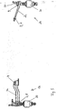
- the cab support according to the invention is shown in a perspective view. In order to increase the clarity of the graphic representation, all components of the cab cab and the vehicle frame or other vehicle body were not shown.
- the cab bearing shown in Figure 1 has two front storage facilities 1 a, 1b.
- Each of the front bearing devices 1 a, 1 b has a three-point linkage arrangement 3 a, 3 b.
- the three-point linkage assembly 3a, 3b are each formed as a wishbone. This can be designed as einschaliges sheet metal stamping or as a multi-shell profile component.
- a frame connection element is provided at the frame connection point 4. This is designed as a screw-on plate with fastening tabs.
- 3b cab connection points 5, 6 are arranged on the seen in the direction of travel front end of the wishbone 3a.
- the two cabin connection points of each wishbone 3a, 3b are at the same spatial level.
- 3b further fasteners 20 are arranged, which are connectable to the cab cab.
- a spring-damper element 30 is arranged in each case.
- These spring-damper elements are based with their the triangular links 3a, 3b remote end on the vehicle body, z. B. from the vehicle frame.
- the two front storage facilities are connected to each other via a stabilizer 40.
- each triangular link 3a, 3b the frame connection point 4 is arranged at a higher spatial level than the cabin connection points 5, 6. Furthermore, it can be seen that the respective cabin connection point 5 closer to the center line of the vehicle is arranged as the respective cabin connection point 6. From the vehicle center line, one can also say that the cabin connection point 5 is an inner cabin connection point and the cabin connection point 6 is an outer cabin connection point.
- the frame connection point 4 of a wishbone 3a, 3b is arranged spatially at a higher level than the two cabin connection points 5, 6.
- the respective wishbone 3a, 3b may also be formed so that the first (inner) Kabinenanitatistician 5 is disposed at a higher level than the second (outer) Kabinenanitatistician 6.
- this embodiment of the invention is not shown in Figure 1.
- each rear bearing device 2a, 2b comprises a three-point linkage arrangement 2c.
- the three-point linkage assembly 2c is designed as a wishbone in sheet metal shell construction. It may be a single-shell construction in the form of a sheet metal stamping. Likewise it can be a two-shelled or even Merchalige Act construction, in which the wishbone is composed of several profiles or Blechpressieri.
- the wishbone 2c has a first 7 and a second frame connection point 8 for the connection of the wishbone 2c to the vehicle body.
- the wishbone is arranged so that the frame connection point 7 is arranged closer to the vehicle centerline than the frame connection point 8.
- the wishbone 2c is oriented so that the frame connection points 7, 8 are arranged at a higher spatial level than the cabin connection point 9. Particularly advantageous It is, if at the same time also seen from the vehicle center inside, d. H. Frame connection point 7 lying closer to the centerline of the vehicle is arranged at a higher level than the outer frame connection point 8. This embodiment of the invention is shown in FIG. 2b and will be described in more detail below.
- a cabin connection point 9 is arranged at the rear end of each wishbone 2c seen in the direction of travel.
- a lock pin 50 is provided which serves to connect the wishbone 2c to the cab.
- the cab then has a Domanitati with a lock, in which the lock pin 50 is inserted and in which the lock pin can be locked.
- each rear bearing device 2a, 2b has an approximately crescent-shaped recess 51.
- a spring-damper device 30 is provided, which is supported at its end remote from the cabin connection point 9 on the vehicle body.
- FIG. 2a shows the cab suspension according to FIG. 1 in a view in the direction of travel.
- Seen from the vehicle center inside frame connection points 7 of the wishbone 2c are arranged on the same spatial level as the outer frame connection points 8.
- Good to see is also seen in the direction of travel rear cabin connection point 9 of the wishbone 2c.
- This carries a lock pin 50 for connecting the wishbone 2c to the cab.
- the cab attachment point 9 of each wishbone 2c is at a lower spatial level than the frame attachment points 7, 8 of the wishbone 2c.
- the spring-damper units 30 arranged one behind the other in the direction of travel can also be seen, as well as the stabilizer 40 interconnecting the front bearing devices.
- the front bearing devices 1a, 1b are largely shown in FIG. 2a by the rear bearing devices 2a. 2b hidden.
- FIG. 2 b shows an embodiment of the invention modified with respect to FIG. 2 a.
- the view from behind in the direction of travel shown in Figure 2b is the same view shown in Figure 2a.
- the vehicle interior ie the frame connection points 7 arranged closer to the vehicle center
- the vehicle exterior ie farther away from the vehicle center
- the wishbone 2c are also arranged transversely to the direction of travel obliquely, so that in each case the vehicle interior frame connection point 7 is arranged at a higher level in space than the respective vehicle outer frame connection point 8.
- This additional oblique employment of the wishbone 2c further targeted displacement of the rear roller center is achieved. Due to the double oblique position of the wishbone, the position of the rear roller center in
- FIG. 3 the cab support according to the invention shown in FIG. 2a is shown in side view.
- a front bearing device 1a and a rear bearing device 2a can be seen.
- the frame connection point 4 of the front bearing device 1 a is arranged spatially at a higher level than the cabin connection points 5, 6 lying one behind the other in FIG. 3. This is achieved by a corresponding shaping of the three-point link 3a. This has a cranking, by which the frame connection point 4 is brought to a higher level than the cabin connection points 5, 6.
- the rear bearing device 2 has a triangular link 2c, in which the frame connection points 7, 8 arranged transversely to the direction of travel are arranged at the same height level. In contrast, the frame connection points 7, 8 arranged on a higher spatial level than the cabin connection point 9 of the wishbone 2c. This is achieved by a corresponding employment of the wishbone 2c relative to the horizontal.
- Figure 4 shows the embodiment of the invention according to FIG 2b in a side view transverse to the direction of travel.
- the double oblique employment of the wishbone 2c on the one hand in the direction of travel and on the other hand transverse to the direction of travel can be seen particularly well.
- the respective frame connection points 7, 8 are at a higher level in space than the respective cabin connection points 9, and at the same time, on the other hand, the frame connection point 7 arranged closer to the vehicle center is at a higher level in space than the respective one, further away from the vehicle center Frame connection point 8.
Abstract
Description
- Die Erfindung betrifft eine Fahrerhauslagerung für Nutzfahrzeuge gemäß dem Oberbegriff des Patentanspruchs 1.
- Eine derartige Fahrerhauslagerung ist aus dem Stand der Technik (
DE 101 13 798 A1 ) bekannt. Bei dieser bekannten Fahrerhauslagerung soll die bewegliche und elastische Aufhängung des Fahrerhauses Verwindungen des Rahmens und Schwingungen vom Fahrerhaus fernhalten und den Komfort der Insassen erhöhen. Hierzu sollen Rollbewegungen (Drehung um die Fahrzeuglängsachse) des Fahrerhauses, vor allem bei Kurvenfahrten, verhindert werden. Um derartige Rollbewegungen zu verhindern, sollte der Schwerpunkt des Fahrerhauses im so genannten Rollzentrum liegen. Um dies zu erreichen, schlägt dieDE 101 13 798 A1 vor, dass auf beiden Seiten je ein Längslenker und ein Schräglenker vorgesehen sind, die mit einem Ende am Träger des Fahrerhauses und mit dem anderen Ende an rahmenfesten Lagern angelenkt sind, dass der Träger des Fahrerhauses beiderseits je ein erstes Anlenklager für den Längslenker und je ein zweites Anlenklager für den Schräglenker besitzt, wobei die beiden Anlenklager jeweils in verschiedener Höhe und in verschiedenem Abstand von der Längsmitte des Fahrzeuges angeordnet sind, und dass am Rahmen des Fahrzeuges beiderseits je ein einziges rahmenfestes Lager für das eine Ende des Längslenkers und für das eine Ende des Schräglenkers vorgesehen ist. Durch diese Konstruktion gelingt es, das Rollzentrum deutlich nach oben zu verschieben, so dass es in der Nähe des Schwerpunktes des Fahrerhauses angeordnet ist. - Die in der
DE 101 13 798 A1 vorgeschlagenen Maßnahmen beschränken sich auf die vorderen Fahrerhauslagerungseinrichtungen und beschäftigen sich lediglich mit dem Einfluss, den die Geometrie der vorderen Fahrerhauslagerungen auf die Lage des Rollzentrums im Verhältnis zum Schwerpunkt des Fahrerhauses hat. Nachteilig ist dabei, dass der Fahrkomfort durch diese Maßnahmen zwar verbessert wird, jedoch ist der erreichte Fahrkomfort weiter verbesserungsfähig. Nachteilig ist weiter, dass eine mehrere Einzellenker umfassende Lenkeranordnung vorgesehen ist, was den Fertigungs- und Montageaufwand erhöht. - Der Erfindung liegt die Aufgabe zugrunde, eine Fahrerhauslagerung mit den Merkmalen des Oberbegriffes des Patentanspruchs 1 derart weiterzubilden, dass der Fahrkomfort in der Fahrerhauskabine bei geringem Fertigungs- und Montageaufwand weiter verbessert wird. Diese Aufgabe wird erfindungsgemäß durch eine Fahrerhauslagerung mit den Merkmalen des Patentanspruchs 1 gelöst. Vorteilhafte Ausgestaltungen der erfindungsgemäßen Fahrerhauslagerung sind in den Unteransprüchen angegeben.
- Die Erfindung geht von der Erkenntnis aus, dass durch kinematische und konstruktive Änderungen der Lagereinrichtungen von Fahrerhauslagerungen die Lage der Wankachse und der Nickachse einer Fahrerhauskabine gezielt verlagert werden kann, indem ein erstes, den vorderen Lagereinrichtungen der Fahrerhauslagerung zugeordnetes Rollzentrum und ein zweites, der hinteren Lagereinrichtung der Fahrerhauslagerung zugeordnetes Rollzentrum gezielt verlagert und dadurch so positioniert werden können, dass die Wankachse und die Nickachse in der Nähe des Kabinenschwerpunktes verlaufen. Durch diese Maßnahme wird der vom Schwerpunkt der Fahrerhauskabine aus bestehende jeweilige Hebelarm zu der Wankachse bzw. der Nickachse des Fahrerhauses minimiert, so dass die rotatorischen Bewegungen der Kabine minimiert werden. Derartige rotatorische Bewegungen der Kabine treten insbesondere bei Schaltvorgängen, beim Anfahren und beim Bremsen sowie auch bei unebener Straße und Kurvenfahrt auf. Erfindungsgemäß wurde erkannt, dass diese unerwünschten rotatorischen Bewegungen durch die gezielte, aufeinander abgestimmte Ausrichtung der vorderen Lagereinheiten und der mindestens einen hinteren Lagereinheit der Fahrerhauslagerung verringert bzw. minimiert werden können.
- Erfindungsgemäß weisen die vorderen Lagereinrichtungen der Fahrerhauslagerung je zwei räumlich angestellte Dreipunktlenker auf. Diese Dreipunkt-Lenker können insbesondere als Dreipunkt-Schräglenker ausgebildet sein. Je nach gewünschter Kinematik können die Dreipunkt-Schräglenker im Extremfall auch als räumlich angestellte Längslenker oder auch als räumlich angestellte Querlenker ausgeführt sein. Um die Wankachse und die Nickachse signifikant nach den Bedürfnissen der Kinematik auslegen zu können, ist es gemäß einer der vorliegenden Erfindung zugrunde liegenden Erkenntnis erforderlich, neben den vorderen Lagereinrichtungen der Fahrerhauslagerung auch die hintere Lagereinrichtung der Fahrerhauslagerung zu betrachten und mit in die Konstruktion einzubeziehen, indem die hintere und die vorderen Lagereinrichtungen aufeinander abgestimmt werden. Erfindungsgemäß ist bei der hinteren Lagereinrichtung ebenso wie bei den vorderen Lagereinrichtungen der Einsatz räumlich angeordneter Dreipunktlenker, insbesondere Dreipunkt-Schräglenker vorgesehen.
- Zusätzlich kann bei der hinteren Lagereinrichtung der Kabinenanbindungspunkt einen Schlosszapfen aufweisen, der in das Schloss einer Domanbindung des Fahrerhauses einführbar und mit diesem verriegelbar ist. Auf diese Weise können die aufgrund der erfindungsgemäß ausgebildeten Kinematik entstehenden Kräfte in Längs-, Quer- und Vertikalrichtung aufgenommen werden. Gleichzeitig wird es dadurch ermöglicht, das Fahrerhaus in Fahrtrichtung gesehen nach vorne abkippen zu können. Dies ist beispielsweise erforderlich, um Wartungs- und Reparaturarbeiten am Motor vornehmen zu können.
- Durch die erfindungsgemäße räumliche Anordnung der Lenker der vorderen und hinteren Lagereinrichtungen lassen sich sowohl die Wankachse als auch die Nickachse korrespondierend zur räumlichen Anordnung frei verschieben und optimal auf die Anforderungen ausrichten. Dadurch wird eine große Steigerung des Fahrkomforts bei einem ausgewogenen Kosten-Nutzenverhältnis erreicht, ohne dass ein aufwändiges und kostenintensives aktives System erforderlich ist.
- Im Folgenden wird die Erfindung anhand eines Ausführungsbeispiels näher erläutert. Im Einzelnen zeigen
- Figur 1
- eine erfindungsgemäße Fahrerhauslagerung mit vorderen und hinteren Lagereinrichtungen in einer perspektivischen Darstellung,
- Figur 2a
- die Fahrerhauslagerung gemäß Figur 1 in einer Ansicht von hinten in Fahrtrichtung,
- Fig. 2b
- eine Fahrerhauslagerung in einer Ansicht in Fahrtrichtung in einer gegenüber Figur 2a abgewandelten Ausführungsform,
- Figur 3
- die erfindungsgemäße Fahrerhauslagerung gemäß Figur 2a in einer Seitenansicht,
- Figur 4
- die Fahrerhauslagerung gemäß Figur 2b in einer Seitenansicht.
- In Figur 1 ist die erfindungsgemäße Fahrerhauslagerung in einer perspektivischen Ansicht dargestellt. Um die Klarheit der zeichnerischen Darstellung zu erhöhen, wurden alle Bauteile der Fahrerhauskabine und des Fahrzeugrahmens bzw. sonstigen Fahrzeugaufbaus nicht dargestellt.
- Die in Figur 1 dargestellte Fahrerhauslagerung weist zwei vordere Lagereinrichtungen 1 a, 1b auf. Jede der vorderen Lagereinrichtungen 1 a, 1b weist eine Dreipunktlenkeranordnung 3a, 3b auf. Im dargestellten Ausführungsbeispiel ist die Dreipunktlenkeranordnung 3a, 3b jeweils als Dreieckslenker ausgebildet. Dieser kann als einschaliges Blechpressteil oder auch als mehrschaliges Profilbauteil ausgebildet sein.
- An dem in Fahrtrichtung gesehen hinten liegenden Ende des Dreipunktlenkers 3a, 3b ist jeweils ein Rahmenanbindungspunkt 4 für die Anbindung des Dreipunktlenkers 3a, 3b an den nicht dargestellten Fahrzeugaufbau angeordnet. An dem Rahmenanbindungspunkt 4 ist ein Rahmenanbindungselement vorgesehen. Dieses ist als anschraubbare Platte mit Befestigungslaschen ausgebildet. An dem in Fahrtrichtung gesehen vorderen Ende der Dreieckslenker 3a, 3b sind Kabinenanbindungspunkte 5, 6 angeordnet. Bei dem in Figur 1 dargestellten Ausführungsbeispiel befinden sich die beiden Kabinenanbindungspunkte jedes Dreieckslenkers 3a, 3b auf demselben räumlichen Niveau. Auf dem jeweiligen Dreieckslenker 3a, 3b sind weiter Befestigungselemente 20 angeordnet, welche mit der Fahrerhauskabine verbindbar sind.
- Unter dem jeweiligen Dreiecklenker 3a, 3b ist jeweils ein Feder-Dämpfer-Element 30 angeordnet. Diese Feder-Dämpfer-Elemente stützen sich mit ihrem den Dreieckslenkern 3a, 3b abgewandten Ende auf dem Fahrzeugaufbau, z. B. auf dem Fahrzeugrahmen ab.
- Die beiden vorderen Lagereinrichtungen sind über einen Stabilisator 40 miteinander verbunden.
- In der räumlichen Darstellung der Figur 1 ist zu erkennen, dass bei jedem Dreieckslenker 3a, 3b der Rahmenanbindungspunkt 4 auf einem höheren räumlichen Niveau angeordnet ist, als die Kabinenanbindungspunkte 5, 6. Weiterhin ist zu erkennen, dass der jeweilige Kabinenanbindungspunkt 5 näher an der Mittellinie des Fahrzeugs angeordnet ist, als der jeweilige Kabinenanbindungspunkt 6. Von der Fahrzeugmittellinie aus gesehen, kann man auch davon sprechen, dass der Kabinenanbindungspunkt 5 ein innerer Kabinenanbindungspunkt und der Kabinenanbindungspunkt 6 ein äußerer Kabinenanbindungspunkt ist.
- Gemäß der Erfindung muss zumindest sichergestellt sein, dass der Rahmenanbindungspunkt 4 eines Dreieckslenkers 3a, 3b räumlich gesehen auf einem höheren Niveau angeordnet ist als die beiden Kabinenanbindungspunkte 5, 6.
- Zusätzlich kann der jeweilige Dreieckslenker 3a, 3b auch so ausgebildet sein, dass der erste (innere) Kabinenanbindungspunkt 5 auf einem höheren Niveau angeordnet ist, als der zweite (äußere) Kabinenanbindungspunkt 6. Diese Ausführungsform der Erfindung ist jedoch in Figur 1 nicht dargestellt.
- Bei dem in Figur 1 dargestellten Ausführungsbeispiel sind zwei hintere Lagereinrichtungen 2a, 2b vorgesehen. Jede hintere Lagereinrichtung 2a, 2b umfasst eine Dreipunktlenkeranordnung 2c. Im dargestellten Ausführungsbeispiel ist die Dreipunktlenkeranordnung 2c als Dreieckslenker in Blechschalenbauweise ausgeführt. Es kann sich dabei um eine einschalige Bauweise in Form eines Blechpressteils handeln. Ebenso kann es sich um eine zweischalige oder sogar mehrschalige Bauweise handeln, bei der der Dreieckslenker aus mehreren Profilen bzw. Blechpressteilen zusammengesetzt ist.
- Der Dreieckslenker 2c weist einen ersten 7 und einen zweiten Rahmenanbindungspunkt 8 für die Anbindung des Dreieckslenkers 2c an den Fahrzeugaufbau auf. Dabei ist der Dreieckslenker so angeordnet, dass der Rahmenanbindungspunkt 7 näher an der Fahrzeugmittellinie angeordnet ist als der Rahmenanbindungspunkt 8. Erfindungsgemäß ist der Dreieckslenker 2c so ausgerichtet, dass die Rahmenanbindungspunkte 7, 8 auf einem höheren räumlichen Niveau angeordnet sind als der Kabinenanbindungspunkt 9. Besonders vorteilhaft ist es, wenn dabei gleichzeitig auch der von der Fahrzeugmitte aus gesehen innen liegende, d. h. näher an der Fahrzeugmittellinie liegende Rahmenanbindungspunkt 7 auf einem höheren Niveau angeordnet ist als der äußere Rahmenanbindungspunkt 8. Diese Ausführungsform der Erfindung ist in Figur 2b dargestellt und wird weiter unten näher beschrieben.
- An dem in Fahrtrichtung gesehen hinteren Ende jedes Dreieckslenkers 2c ist ein Kabinenanbindungspunkt 9 angeordnet. An dem Kabinenanbindungspunkt 9 ist ein Schlosszapfen 50 vorgesehen, welcher zur Verbindung des Dreieckslenkers 2c mit dem Fahrerhaus dient. Das Fahrerhaus weist dann eine Domanbindung mit einem Schloss auf, in welches der Schlosszapfen 50 einführbar ist und in welchem der Schlosszapfen verriegelt werden kann.
- Um Gewicht zu sparen, weist der Dreieckslenker 2c jeder hinteren Lagereinrichtung 2a, 2b eine etwa sichelförmige Ausnehmung 51 auf. Unterhalb des Kabinenanbindungspunktes 9 ist eine Feder-Dämpfer-Einrichtung 30 vorgesehen, die sich mit ihrem dem Kabinenanbindungspunkt 9 abgewandten Ende an dem Fahrzeugaufbau abstützt.
- Durch die in Figur 1 dargestellte Kombination der Ausrichtung der vorderen Dreipunktlenkeranordnung 3a und 3b und der hinteren Dreipunktlenkeranordnung 2c im Raum wird eine Verlagerung des hinteren und des vorderen Rollzentrums in Richtung Schwerpunkt der Fahrerhauskabine erreicht. Dadurch verläuft sowohl die Wankachse als auch die Nickachse der Fahrerhauskabine in der Nähe des Fahrerhauskabinenschwerpunktes. Dadurch wird ein besonders geringer Abstand zwischen dem Fahrerhauskabinenschwerpunkt einerseits und der Wankachse und der Nickachse andererseits erreicht, so dass die den Fahrkomfort negativ beeinflussenden rotatorischen Bewegungen um die Wankachse und die Nickachse auf ein Minimum reduziert werden. Im Idealfall kann es sogar erreicht werden, dass die Wankachse und die Nickachse durch den Fahrerhauskabinenschwerpunkt verläuft, so dass der Hebelarm für die unerwünschten rotatorischen Bewegungen gleich Null wird und diese somit entfallen.
- In Figur 2a ist die Fahrerhauslagerung gemäß Figur 1 in einer Ansicht in Fahrtrichtung dargestellt. Gut zu erkennen sind die schräg zur Fahrzeugmitte hin ansteigend ausgerichteten Dreieckslenker 2c der hinteren Lagereinrichtungen 2a, 2b. Die von der Fahrzeugmitte aus gesehen innen liegenden Rahmenanbindungspunkte 7 der Dreieckslenker 2c sind auf dem gleichen räumlichen Niveau angeordnet wie die äußeren Rahmenanbindungspunkte 8. Gut zu erkennen ist auch der in Fahrtrichtung gesehen hintere Kabinenanbindungspunkt 9 des Dreieckslenkers 2c. Dieser trägt einen Schlosszapfen 50 zur Verbindung des Dreieckslenkers 2c mit dem Fahrerhaus. Es ist ebenfalls zu erkennen, dass sich der Kabinenanbindungspunkt 9 jedes Dreieckslenkers 2c auf einem niedrigeren räumlichen Niveau befindet als die Rahmenanbindungspunkte 7, 8 des Dreieckslenkers 2c.
- In Figur 2a sind ebenfalls die in Fahrtrichtung gesehen hintereinander angeordneten Feder-Dämpfer-Einheiten 30 zu erkennen, sowie der die vorderen Lagereinrichtungen miteinander verbindende Stabilisator 40. Die vorderen Lagereinrichtungen 1a, 1b sind in der Darstellung in Figur 2a größtenteils von den hinteren Lagereinrichtungen 2a, 2b verdeckt.
- In Figur 2b ist eine gegenüber Figur 2a abgewandelte Ausführungsform der Erfindung dargestellt. Die in Figur 2b dargestellte Ansicht von hinten in Fahrtrichtung ist dieselbe Ansicht, die in Figur 2a dargestellt ist. Im Unterschied zu Figur 2a sind bei der in Figur 2b dargestellten Ausführungsform bei beiden hinteren Lagereinrichtungen 2a, 2b die fahrzeuginneren, d.h. die näher zur Fahrzeugmitte hin angeordneten Rahmenanbindungspunkte 7 auf einem räumlich höheren Niveau angeordnet als die fahrzeugäußeren, d.h. weiter von der Fahrzeugmitte weg angeordneten Rahmenanbindungspunkte 8. Zusätzlich zu der schrägen Anstellung des Dreieckslenkers 2c in Fahrtrichtung, durch die die jeweiligen Rahmenanbindungspunkte 7, 8 auf einem höheren räumlichen Niveau angeordnet sind als die jeweiligen Kabinenanbindungspunkte 9, sind die Dreieckslenker 2c auch quer zur Fahrtrichtung schräg angeordnet, so dass jeweils der fahrzeuginnere Rahmenanbindungspunkt 7 auf einem höheren Niveau im Raum angeordnet ist als der jeweilige fahrzeugäußere Rahmenanbindungspunkt 8. Durch diese zusätzliche schräge Anstellung der Dreieckslenker 2c wird eine weitere gezielte Verlagerung des hinteren Rollzentrums erreicht. Durch die doppelt schräge Anstellung des Dreieckslenkers kann die Lage des hinteren Rollzentrums im Raum somit besonders gut beeinflusst werden.
- In Figur 3 ist die erfindungsgemäße Fahrerhauslagerung gemäß Fig. 2a in der Seitenansicht dargestellt. Einer besseren Übersichtlichkeit wegen ist nur die jeweils vordere und hintere Lagereinrichtung einer Fahrzeughälfte dargestellt. Zu erkennen ist jeweils eine vordere Lagereinrichtung 1 a und eine hintere Lagereinrichtung 2a. In dieser Seitenansicht ist besonders gut zu erkennen, dass der Rahmenanbindungspunkt 4 der vorderen Lagereinrichtung 1 a räumlich auf einem höheren Niveau angeordnet ist als die in Figur 3 hintereinander liegenden Kabinenanbindungspunkte 5, 6. Dies wird durch eine entsprechende Ausformung des Dreipunktlenkers 3a erreicht. Dieser weist eine Kröpfung auf, durch die der Rahmenanbindungspunkt 4 auf ein höheres Niveau gebracht wird als die Kabinenanbindungspunkte 5, 6.
- Die hintere Lagereinrichtung 2 weist einen Dreieckslenker 2c auf, bei dem die Rahmenanbindungspunkte 7, 8 quer zur Fahrtrichtung gesehen auf demselben Höhenniveau angeordnet sind. Dagegen sind die Rahmenanbindungspunkte 7, 8 auf einem räumlich höheren Niveau angeordnet als der Kabinenanbindungspunkt 9 des Dreieckslenkers 2c. Dies wird durch eine entsprechende Anstellung des Dreieckslenkers 2c gegenüber der Horizontalen erreicht.
- Unter dem Kabinenanbindungspunkt 9 des Dreieckslenkers 2c ist wiederum die Feder-Dämpfer-Einheit 30 angeordnet. Analog ist die Feder-Dämpfer-Einheit 30 bei der vorderen Lagereinrichtung 1a unter den Kabinenanbindungspunkten 5, 6 angeordnet.
- Figur 4 zeigt die Ausführungsform der Erfindung gemäß Figur 2b in einer Seitenansicht quer zur Fahrtrichtung. Analog zu Figur 3 sind nur die vorderen Lagereinrichtung 1 a und die hintere Lagereinrichtung 2a einer Fahrzeughälfte dargestellt, um eine bessere Übersichtlichkeit zu erreichen. In dieser Darstellung ist die doppelt schräge Anstellung des Dreieckslenkers 2c einerseits in Fahrtrichtung und andererseits quer zur Fahrtrichtung besonders gut zu erkennen. Einerseits befinden sich die jeweiligen Rahmenanbindungspunkte 7, 8 auf einem höheren Niveau im Raum als die jeweiligen Kabinenanbindungspunkte 9, und gleichzeitig befindet sich andererseits der näher zur Fahrzeugmitte hin angeordnete Rahmenanbindungspunkt 7 auf einem höheren Niveau im Raum als der jeweilige, weiter von der Fahrzeugmitte weg angeordnete Rahmenanbindungspunkt 8.
-
- 1 a
- vordere Lagereinrichtung
- 1 b
- vordere Lagereinrichtung
- 2, 2a
- hintere Lagereinrichtung
- 2c
- Dreipunkt-Lenkeranordnung; Dreieckslenker
- 3a, 3b
- Dreipunkt-Lenkeranordnung; Dreieckslenker
- 4
- Rahmenanbindungspunkt
- 5
- Kabinenanbindungspunkt
- 6
- Kabinenanbindungspunkt
- 7
- Rahmenanbindungspunkt
- 8
- Rahmenanbindungspunkt
- 9
- Kabinenanbindungspunkt
- 20
- Befestigungselement
- 30
- Feder-Dämpfer-Einheit
- 40
- Stabilisator
- 50
- Schlosszapfen
- 51
- Ausnehmung
Claims (4)
- Fahrerhauslagerung für Nutzfahrzeuge, umfassenda) in Fahrtrichtung gesehen zwei vordere Lagereinrichtungen (1a, 1 b) und mindestens eine hintere Lagereinrichtung (2),b) jede vordere Lagereinrichtung weist eine Dreipunkt-Lenkeranordnung (3a, 3b), einen Rahmenanbindungspunkt (4) für die Anbindung der Dreipunkt-Lenkeranordnung (3a, 3b) an den Fahrzeugaufbau und einen ersten (5) und einen zweiten Kabinenanbindungspunkt (6) für die Anbindung der Dreipunkt-Lenkeranordnung an die Fahrerhauskabine auf, wobei der erste Kabinenanbindungspunkt (5) näher an der Fahrzeugmittellinie angeordnet ist als der zweite Kabinenanbindungspunkt (6), dadurch gekennzeichnet,c) dass die mindestens eine hintere Lagereinrichtung (2) eine Dreipunkt-Lenkeranordnung (2c), einen ersten (7) und einen zweiten Rahmenanbindungspunkt (8) für die Anbindung der Dreipunkt-Lenkeranordnung (2c) an den Fahrzeugaufbau und einen Kabinenanbindungspunkt (9) für die Anbindung der Dreipunkt-Lenkeranordnung an die Fahrerhauskabine aufweist, wobei der erste Rahmenanbindungspunkt (7) näher an der Fahrzeugmittellinie angeordnet ist als der zweite Rahmenanbindungspunkt,d) dass die Dreipunkt-Lenkeranordnungen (3a, 3b) der vorderen Lagereinrichtungen (1 a, 1 b) jeweils so ausgerichtet sind, dass der Rahmenanbindungspunkt (4) auf einem höheren Niveau angeordnet ist als die Kabinenanbindungspunkte (5, 6),e) und dass die Dreipunkt-Lenkeranordnung (2c) der hinteren Lagereinrichtung (2) so ausgerichtet ist, dass der erste Rahmenanbindungspunkt (7) und der zweite Rahmenanbindungspunkt (8) auf einem höheren Niveau angeordnet sind als der Kabinenanbindungspunkt (9).
- Fahrerhauslagerung nach Anspruch 1, dadurch gekennzeichnet, dass die Dreipunkt-Lenkeranordnungen (3a, 3b) der vorderen Lagereinrichtungen (1a, 1 b) jeweils so ausgerichtet sind, dass der erste Kabinenanbindungspunkt (5) auf einem höheren Niveau angeordnet ist als der zweite Kabinenanbindungspunkt (6).
- Fahrerhauslagerung nach Anspruch 1 oder 2, dadurch gekennzeichnet, dass die Dreipunkt-Lenkeranordnung (2c) so ausgerichtet ist, dass der erste Rahmenanbindungspunkt (7) auf einem höheren Niveau angeordnet ist als der zweite Rahmenanbindungspunkt (8).
- Fahrerhauslagerung nach einem der vorhergehenden Ansprüche, dadurch gekennzeichnet, dass zwei gleich aufgebaute hintere Lagereinrichtungen (2a, 2b) vorgesehen sind.
Applications Claiming Priority (1)
| Application Number | Priority Date | Filing Date | Title |
|---|---|---|---|
| DE102006044150A DE102006044150A1 (de) | 2006-09-15 | 2006-09-15 | Fahrerhauslagerung |
Publications (3)
| Publication Number | Publication Date |
|---|---|
| EP1900616A2 true EP1900616A2 (de) | 2008-03-19 |
| EP1900616A3 EP1900616A3 (de) | 2009-06-17 |
| EP1900616B1 EP1900616B1 (de) | 2011-06-29 |
Family
ID=38829627
Family Applications (1)
| Application Number | Title | Priority Date | Filing Date |
|---|---|---|---|
| EP07017445A Not-in-force EP1900616B1 (de) | 2006-09-15 | 2007-09-06 | Fahrerhauslagerung |
Country Status (3)
| Country | Link |
|---|---|
| EP (1) | EP1900616B1 (de) |
| AT (1) | ATE514618T1 (de) |
| DE (1) | DE102006044150A1 (de) |
Cited By (1)
| Publication number | Priority date | Publication date | Assignee | Title |
|---|---|---|---|---|
| CN107848580A (zh) * | 2015-07-25 | 2018-03-27 | 戴姆勒股份公司 | 用于将驾驶室支承在商用车的车架上的支承装置 |
Families Citing this family (4)
| Publication number | Priority date | Publication date | Assignee | Title |
|---|---|---|---|---|
| DE102010035976A1 (de) | 2010-09-01 | 2011-05-12 | Daimler Ag | Geteilter Stabilisator einer Nutzfahrzeug-Fahrerhauslagerung |
| DE102010055947A1 (de) | 2010-12-23 | 2011-08-25 | Daimler AG, 70327 | Hintere Lagerung eines Nutzfahrzeugfahrerhauses |
| DE102012003450A1 (de) | 2012-02-21 | 2012-10-11 | Daimler Ag | Fahrerhausaufhängung eines Nutzkraftfahrzeugs |
| DE102012008150A1 (de) | 2012-04-24 | 2013-10-24 | Man Truck & Bus Ag | Fahrerhauslagerung |
Citations (2)
| Publication number | Priority date | Publication date | Assignee | Title |
|---|---|---|---|---|
| EP0043532A2 (de) | 1980-07-07 | 1982-01-13 | Siemens Aktiengesellschaft | Digitale Halbleiterschaltung für eine elektronische Orgel |
| EP0943532A2 (de) | 1998-03-18 | 1999-09-22 | Hino Jidosha Kogyo Kabushiki Kaisha | Aufhängung für ein Fahrerhaus |
Family Cites Families (4)
| Publication number | Priority date | Publication date | Assignee | Title |
|---|---|---|---|---|
| JPS61157070U (de) * | 1985-03-22 | 1986-09-29 | ||
| SE9602297L (sv) * | 1996-06-07 | 1997-11-10 | Scania Cv Ab | Motorfordon innefattande fjädrande uppburen fordonshytt |
| ATA4562000A (de) * | 2000-03-20 | 2001-07-15 | Steyr Antriebstechnik Ges M B | Nutzfahrzeug mit elastisch aufgehängtem fahrerhaus |
| ATA4772000A (de) * | 2000-03-21 | 2001-07-15 | Steyr Antriebstechnik Ges M B | Nutzfahrzeug mit elastisch aufgehängtem fahrerhaus |
-
2006
- 2006-09-15 DE DE102006044150A patent/DE102006044150A1/de not_active Ceased
-
2007
- 2007-09-06 AT AT07017445T patent/ATE514618T1/de active
- 2007-09-06 EP EP07017445A patent/EP1900616B1/de not_active Not-in-force
Patent Citations (2)
| Publication number | Priority date | Publication date | Assignee | Title |
|---|---|---|---|---|
| EP0043532A2 (de) | 1980-07-07 | 1982-01-13 | Siemens Aktiengesellschaft | Digitale Halbleiterschaltung für eine elektronische Orgel |
| EP0943532A2 (de) | 1998-03-18 | 1999-09-22 | Hino Jidosha Kogyo Kabushiki Kaisha | Aufhängung für ein Fahrerhaus |
Cited By (1)
| Publication number | Priority date | Publication date | Assignee | Title |
|---|---|---|---|---|
| CN107848580A (zh) * | 2015-07-25 | 2018-03-27 | 戴姆勒股份公司 | 用于将驾驶室支承在商用车的车架上的支承装置 |
Also Published As
| Publication number | Publication date |
|---|---|
| ATE514618T1 (de) | 2011-07-15 |
| EP1900616B1 (de) | 2011-06-29 |
| DE102006044150A1 (de) | 2008-03-27 |
| EP1900616A3 (de) | 2009-06-17 |
Similar Documents
| Publication | Publication Date | Title |
|---|---|---|
| DE60125410T2 (de) | Fahrzeugaufhängungssystem | |
| EP3303098B1 (de) | Radaufhängungsanordnung | |
| DE102004028161B4 (de) | Unterfahrschutz für Personenkraftfahrzeuge zur Anordnung unter Längsträgerniveau vor einem Hilfsrahmen oder Achsträger als zusätzliche Crashebene | |
| DE102013020563B4 (de) | Aktiv verstellbare Radaufhängung für die Räder einer Achse eines Kraftfahrzeugs | |
| DE60008009T2 (de) | Einzelradaufhängung | |
| EP3386840B1 (de) | Hinterachshilfsrahmen sowie kraftfahrzeug mit einem derartigen hinterachshilfsrahmen | |
| DE102014205632A1 (de) | Einzelradaufhängung sowie Hinterachse mit Einzelradaufhängungen für ein Fahrzeug und entsprechend ausgestattetes Fahrzeug | |
| EP3400140B1 (de) | Radaufhängung | |
| DE4200482A1 (de) | Aufhaengungstragestruktur fuer ein selbstfahrendes fahrzeug | |
| DE102020126656A1 (de) | Karosserie für ein fahrzeug | |
| EP1900616B1 (de) | Fahrerhauslagerung | |
| DE102015009474A1 (de) | Halteeinrichtung zum schwenkbaren Halten eines Fahrerhauses an einem Rahmen eines Nutzfahrzeugs | |
| DE102020130723A1 (de) | Kupplungsstruktur einer Radaufhängung | |
| DE102015209595B4 (de) | Radaufhängungsanordnung | |
| EP3071874B1 (de) | Anordnung eines druckgastanks in einem zweispurigen kraftfahrzeug | |
| DE10163220A1 (de) | Kraftfahrzeugvorderwagen | |
| WO2022089881A1 (de) | Fahrzeug mit batteriehalterung | |
| WO2016202513A1 (de) | Gelenkverbindung und anordnung zur aufhängung eines rades | |
| DE102017214640A1 (de) | Fahrzeugachse mit einer zentral angeordneten Antriebseinheit | |
| DE102017214639A1 (de) | Radaufhängung für ein Kraftfahrzeug | |
| EP1231083B1 (de) | Achsaufhängung für Starrachsen von Nutzfahrzeugen | |
| DE102013015615B4 (de) | Frontstruktur für ein Kraftfahrzeug | |
| DE102020112535B4 (de) | Radmodul für ein Kraftfahrzeug | |
| DE102017202179A1 (de) | Achsanordnung für ein Fahrzeug und Fahrzeug | |
| DE102017007553B4 (de) | Kraftfahrzeug mit einer Versteifungsvorrichtung und Versteifungsvorrichtung für ein Kraftfahrzeug |
Legal Events
| Date | Code | Title | Description |
|---|---|---|---|
| PUAI | Public reference made under article 153(3) epc to a published international application that has entered the european phase |
Free format text: ORIGINAL CODE: 0009012 |
|
| AK | Designated contracting states |
Kind code of ref document: A2 Designated state(s): AT BE BG CH CY CZ DE DK EE ES FI FR GB GR HU IE IS IT LI LT LU LV MC MT NL PL PT RO SE SI SK TR |
|
| AX | Request for extension of the european patent |
Extension state: AL BA HR MK YU |
|
| PUAL | Search report despatched |
Free format text: ORIGINAL CODE: 0009013 |
|
| AK | Designated contracting states |
Kind code of ref document: A3 Designated state(s): AT BE BG CH CY CZ DE DK EE ES FI FR GB GR HU IE IS IT LI LT LU LV MC MT NL PL PT RO SE SI SK TR |
|
| AX | Request for extension of the european patent |
Extension state: AL BA HR MK RS |
|
| 17P | Request for examination filed |
Effective date: 20091116 |
|
| 17Q | First examination report despatched |
Effective date: 20091207 |
|
| AKX | Designation fees paid |
Designated state(s): AT BE BG CH CY CZ DE DK EE ES FI FR GB GR HU IE IS IT LI LT LU LV MC MT NL PL PT RO SE SI SK TR |
|
| GRAP | Despatch of communication of intention to grant a patent |
Free format text: ORIGINAL CODE: EPIDOSNIGR1 |
|
| GRAS | Grant fee paid |
Free format text: ORIGINAL CODE: EPIDOSNIGR3 |
|
| GRAA | (expected) grant |
Free format text: ORIGINAL CODE: 0009210 |
|
| AK | Designated contracting states |
Kind code of ref document: B1 Designated state(s): AT BE BG CH CY CZ DE DK EE ES FI FR GB GR HU IE IS IT LI LT LU LV MC MT NL PL PT RO SE SI SK TR |
|
| REG | Reference to a national code |
Ref country code: GB Ref legal event code: FG4D Free format text: NOT ENGLISH |
|
| REG | Reference to a national code |
Ref country code: CH Ref legal event code: EP |
|
| REG | Reference to a national code |
Ref country code: IE Ref legal event code: FG4D Free format text: LANGUAGE OF EP DOCUMENT: GERMAN |
|
| REG | Reference to a national code |
Ref country code: DE Ref legal event code: R096 Ref document number: 502007007535 Country of ref document: DE Effective date: 20110818 |
|
| REG | Reference to a national code |
Ref country code: SE Ref legal event code: TRGR |
|
| REG | Reference to a national code |
Ref country code: NL Ref legal event code: VDEP Effective date: 20110629 |
|
| PG25 | Lapsed in a contracting state [announced via postgrant information from national office to epo] |
Ref country code: LT Free format text: LAPSE BECAUSE OF FAILURE TO SUBMIT A TRANSLATION OF THE DESCRIPTION OR TO PAY THE FEE WITHIN THE PRESCRIBED TIME-LIMIT Effective date: 20110629 |
|
| PGFP | Annual fee paid to national office [announced via postgrant information from national office to epo] |
Ref country code: IE Payment date: 20110901 Year of fee payment: 5 |
|
| PG25 | Lapsed in a contracting state [announced via postgrant information from national office to epo] |
Ref country code: FI Free format text: LAPSE BECAUSE OF FAILURE TO SUBMIT A TRANSLATION OF THE DESCRIPTION OR TO PAY THE FEE WITHIN THE PRESCRIBED TIME-LIMIT Effective date: 20110629 Ref country code: GR Free format text: LAPSE BECAUSE OF FAILURE TO SUBMIT A TRANSLATION OF THE DESCRIPTION OR TO PAY THE FEE WITHIN THE PRESCRIBED TIME-LIMIT Effective date: 20110930 Ref country code: SI Free format text: LAPSE BECAUSE OF FAILURE TO SUBMIT A TRANSLATION OF THE DESCRIPTION OR TO PAY THE FEE WITHIN THE PRESCRIBED TIME-LIMIT Effective date: 20110629 Ref country code: LV Free format text: LAPSE BECAUSE OF FAILURE TO SUBMIT A TRANSLATION OF THE DESCRIPTION OR TO PAY THE FEE WITHIN THE PRESCRIBED TIME-LIMIT Effective date: 20110629 |
|
| REG | Reference to a national code |
Ref country code: IE Ref legal event code: FD4D |
|
| PG25 | Lapsed in a contracting state [announced via postgrant information from national office to epo] |
Ref country code: EE Free format text: LAPSE BECAUSE OF FAILURE TO SUBMIT A TRANSLATION OF THE DESCRIPTION OR TO PAY THE FEE WITHIN THE PRESCRIBED TIME-LIMIT Effective date: 20110629 Ref country code: CZ Free format text: LAPSE BECAUSE OF FAILURE TO SUBMIT A TRANSLATION OF THE DESCRIPTION OR TO PAY THE FEE WITHIN THE PRESCRIBED TIME-LIMIT Effective date: 20110629 Ref country code: IE Free format text: LAPSE BECAUSE OF FAILURE TO SUBMIT A TRANSLATION OF THE DESCRIPTION OR TO PAY THE FEE WITHIN THE PRESCRIBED TIME-LIMIT Effective date: 20110629 Ref country code: IS Free format text: LAPSE BECAUSE OF FAILURE TO SUBMIT A TRANSLATION OF THE DESCRIPTION OR TO PAY THE FEE WITHIN THE PRESCRIBED TIME-LIMIT Effective date: 20111029 Ref country code: PT Free format text: LAPSE BECAUSE OF FAILURE TO SUBMIT A TRANSLATION OF THE DESCRIPTION OR TO PAY THE FEE WITHIN THE PRESCRIBED TIME-LIMIT Effective date: 20111031 Ref country code: NL Free format text: LAPSE BECAUSE OF FAILURE TO SUBMIT A TRANSLATION OF THE DESCRIPTION OR TO PAY THE FEE WITHIN THE PRESCRIBED TIME-LIMIT Effective date: 20110629 |
|
| PG25 | Lapsed in a contracting state [announced via postgrant information from national office to epo] |
Ref country code: RO Free format text: LAPSE BECAUSE OF FAILURE TO SUBMIT A TRANSLATION OF THE DESCRIPTION OR TO PAY THE FEE WITHIN THE PRESCRIBED TIME-LIMIT Effective date: 20110629 Ref country code: SK Free format text: LAPSE BECAUSE OF FAILURE TO SUBMIT A TRANSLATION OF THE DESCRIPTION OR TO PAY THE FEE WITHIN THE PRESCRIBED TIME-LIMIT Effective date: 20110629 Ref country code: PL Free format text: LAPSE BECAUSE OF FAILURE TO SUBMIT A TRANSLATION OF THE DESCRIPTION OR TO PAY THE FEE WITHIN THE PRESCRIBED TIME-LIMIT Effective date: 20110629 Ref country code: CY Free format text: LAPSE BECAUSE OF FAILURE TO SUBMIT A TRANSLATION OF THE DESCRIPTION OR TO PAY THE FEE WITHIN THE PRESCRIBED TIME-LIMIT Effective date: 20110629 |
|
| BERE | Be: lapsed |
Owner name: THYSSENKRUPP AUTOMOTIVE SYSTEMS G.M.B.H. Effective date: 20110930 |
|
| PG25 | Lapsed in a contracting state [announced via postgrant information from national office to epo] |
Ref country code: MC Free format text: LAPSE BECAUSE OF NON-PAYMENT OF DUE FEES Effective date: 20110930 |
|
| REG | Reference to a national code |
Ref country code: CH Ref legal event code: PL |
|
| PLBE | No opposition filed within time limit |
Free format text: ORIGINAL CODE: 0009261 |
|
| STAA | Information on the status of an ep patent application or granted ep patent |
Free format text: STATUS: NO OPPOSITION FILED WITHIN TIME LIMIT |
|
| 26N | No opposition filed |
Effective date: 20120330 |
|
| PG25 | Lapsed in a contracting state [announced via postgrant information from national office to epo] |
Ref country code: BE Free format text: LAPSE BECAUSE OF NON-PAYMENT OF DUE FEES Effective date: 20110930 Ref country code: DK Free format text: LAPSE BECAUSE OF FAILURE TO SUBMIT A TRANSLATION OF THE DESCRIPTION OR TO PAY THE FEE WITHIN THE PRESCRIBED TIME-LIMIT Effective date: 20110629 |
|
| PG25 | Lapsed in a contracting state [announced via postgrant information from national office to epo] |
Ref country code: CH Free format text: LAPSE BECAUSE OF NON-PAYMENT OF DUE FEES Effective date: 20110930 Ref country code: LI Free format text: LAPSE BECAUSE OF NON-PAYMENT OF DUE FEES Effective date: 20110930 |
|
| REG | Reference to a national code |
Ref country code: DE Ref legal event code: R097 Ref document number: 502007007535 Country of ref document: DE Effective date: 20120330 |
|
| PG25 | Lapsed in a contracting state [announced via postgrant information from national office to epo] |
Ref country code: MT Free format text: LAPSE BECAUSE OF FAILURE TO SUBMIT A TRANSLATION OF THE DESCRIPTION OR TO PAY THE FEE WITHIN THE PRESCRIBED TIME-LIMIT Effective date: 20110629 |
|
| PG25 | Lapsed in a contracting state [announced via postgrant information from national office to epo] |
Ref country code: ES Free format text: LAPSE BECAUSE OF FAILURE TO SUBMIT A TRANSLATION OF THE DESCRIPTION OR TO PAY THE FEE WITHIN THE PRESCRIBED TIME-LIMIT Effective date: 20111010 |
|
| PG25 | Lapsed in a contracting state [announced via postgrant information from national office to epo] |
Ref country code: LU Free format text: LAPSE BECAUSE OF NON-PAYMENT OF DUE FEES Effective date: 20110906 |
|
| PG25 | Lapsed in a contracting state [announced via postgrant information from national office to epo] |
Ref country code: BG Free format text: LAPSE BECAUSE OF FAILURE TO SUBMIT A TRANSLATION OF THE DESCRIPTION OR TO PAY THE FEE WITHIN THE PRESCRIBED TIME-LIMIT Effective date: 20110929 |
|
| PG25 | Lapsed in a contracting state [announced via postgrant information from national office to epo] |
Ref country code: TR Free format text: LAPSE BECAUSE OF FAILURE TO SUBMIT A TRANSLATION OF THE DESCRIPTION OR TO PAY THE FEE WITHIN THE PRESCRIBED TIME-LIMIT Effective date: 20110629 |
|
| PG25 | Lapsed in a contracting state [announced via postgrant information from national office to epo] |
Ref country code: HU Free format text: LAPSE BECAUSE OF FAILURE TO SUBMIT A TRANSLATION OF THE DESCRIPTION OR TO PAY THE FEE WITHIN THE PRESCRIBED TIME-LIMIT Effective date: 20110629 |
|
| REG | Reference to a national code |
Ref country code: AT Ref legal event code: MM01 Ref document number: 514618 Country of ref document: AT Kind code of ref document: T Effective date: 20120906 |
|
| PG25 | Lapsed in a contracting state [announced via postgrant information from national office to epo] |
Ref country code: AT Free format text: LAPSE BECAUSE OF NON-PAYMENT OF DUE FEES Effective date: 20120906 |
|
| REG | Reference to a national code |
Ref country code: DE Ref legal event code: R082 Ref document number: 502007007535 Country of ref document: DE |
|
| REG | Reference to a national code |
Ref country code: DE Ref legal event code: R081 Ref document number: 502007007535 Country of ref document: DE Owner name: ZF FRIEDRICHSHAFEN AG, DE Free format text: FORMER OWNER: THYSSENKRUPP AUTOMOTIVE SYSTEMS GMBH, 45145 ESSEN, DE Effective date: 20140812 |
|
| PGFP | Annual fee paid to national office [announced via postgrant information from national office to epo] |
Ref country code: GB Payment date: 20140903 Year of fee payment: 8 Ref country code: SE Payment date: 20140911 Year of fee payment: 8 |
|
| REG | Reference to a national code |
Ref country code: FR Ref legal event code: TP Owner name: ZF FRIEDRICHSHAFEN AG, DE Effective date: 20141103 |
|
| PGFP | Annual fee paid to national office [announced via postgrant information from national office to epo] |
Ref country code: IT Payment date: 20140915 Year of fee payment: 8 |
|
| PGFP | Annual fee paid to national office [announced via postgrant information from national office to epo] |
Ref country code: FR Payment date: 20140906 Year of fee payment: 8 |
|
| REG | Reference to a national code |
Ref country code: GB Ref legal event code: 732E Free format text: REGISTERED BETWEEN 20150409 AND 20150415 |
|
| PG25 | Lapsed in a contracting state [announced via postgrant information from national office to epo] |
Ref country code: IE Free format text: LAPSE BECAUSE OF FAILURE TO SUBMIT A TRANSLATION OF THE DESCRIPTION OR TO PAY THE FEE WITHIN THE PRESCRIBED TIME-LIMIT Effective date: 20111230 |
|
| PG25 | Lapsed in a contracting state [announced via postgrant information from national office to epo] |
Ref country code: IT Free format text: LAPSE BECAUSE OF NON-PAYMENT OF DUE FEES Effective date: 20150906 |
|
| REG | Reference to a national code |
Ref country code: SE Ref legal event code: EUG |
|
| GBPC | Gb: european patent ceased through non-payment of renewal fee |
Effective date: 20150906 |
|
| PG25 | Lapsed in a contracting state [announced via postgrant information from national office to epo] |
Ref country code: SE Free format text: LAPSE BECAUSE OF NON-PAYMENT OF DUE FEES Effective date: 20150907 |
|
| REG | Reference to a national code |
Ref country code: FR Ref legal event code: ST Effective date: 20160531 |
|
| PG25 | Lapsed in a contracting state [announced via postgrant information from national office to epo] |
Ref country code: GB Free format text: LAPSE BECAUSE OF NON-PAYMENT OF DUE FEES Effective date: 20150906 |
|
| PG25 | Lapsed in a contracting state [announced via postgrant information from national office to epo] |
Ref country code: FR Free format text: LAPSE BECAUSE OF NON-PAYMENT OF DUE FEES Effective date: 20150930 |
|
| PGFP | Annual fee paid to national office [announced via postgrant information from national office to epo] |
Ref country code: DE Payment date: 20200826 Year of fee payment: 14 |
|
| REG | Reference to a national code |
Ref country code: DE Ref legal event code: R119 Ref document number: 502007007535 Country of ref document: DE |
|
| PG25 | Lapsed in a contracting state [announced via postgrant information from national office to epo] |
Ref country code: DE Free format text: LAPSE BECAUSE OF NON-PAYMENT OF DUE FEES Effective date: 20220401 |