EP1900489B1 - Seitenwandkonstruktion einer Gussform - Google Patents
Seitenwandkonstruktion einer Gussform Download PDFInfo
- Publication number
- EP1900489B1 EP1900489B1 EP07397031A EP07397031A EP1900489B1 EP 1900489 B1 EP1900489 B1 EP 1900489B1 EP 07397031 A EP07397031 A EP 07397031A EP 07397031 A EP07397031 A EP 07397031A EP 1900489 B1 EP1900489 B1 EP 1900489B1
- Authority
- EP
- European Patent Office
- Prior art keywords
- sidewall
- construction
- casting
- surface plate
- sidewall construction
- Prior art date
- Legal status (The legal status is an assumption and is not a legal conclusion. Google has not performed a legal analysis and makes no representation as to the accuracy of the status listed.)
- Active
Links
Images


Classifications
-
- B—PERFORMING OPERATIONS; TRANSPORTING
- B28—WORKING CEMENT, CLAY, OR STONE
- B28B—SHAPING CLAY OR OTHER CERAMIC COMPOSITIONS; SHAPING SLAG; SHAPING MIXTURES CONTAINING CEMENTITIOUS MATERIAL, e.g. PLASTER
- B28B7/00—Moulds; Cores; Mandrels
-
- B—PERFORMING OPERATIONS; TRANSPORTING
- B28—WORKING CEMENT, CLAY, OR STONE
- B28B—SHAPING CLAY OR OTHER CERAMIC COMPOSITIONS; SHAPING SLAG; SHAPING MIXTURES CONTAINING CEMENTITIOUS MATERIAL, e.g. PLASTER
- B28B7/00—Moulds; Cores; Mandrels
- B28B7/0002—Auxiliary parts or elements of the mould
- B28B7/0014—Fastening means for mould parts, e.g. for attaching mould walls on mould tables; Mould clamps
- B28B7/002—Fastening means for mould parts, e.g. for attaching mould walls on mould tables; Mould clamps using magnets
-
- B—PERFORMING OPERATIONS; TRANSPORTING
- B28—WORKING CEMENT, CLAY, OR STONE
- B28B—SHAPING CLAY OR OTHER CERAMIC COMPOSITIONS; SHAPING SLAG; SHAPING MIXTURES CONTAINING CEMENTITIOUS MATERIAL, e.g. PLASTER
- B28B7/00—Moulds; Cores; Mandrels
- B28B7/0002—Auxiliary parts or elements of the mould
- B28B7/0014—Fastening means for mould parts, e.g. for attaching mould walls on mould tables; Mould clamps
- B28B7/0017—Fastening means for mould parts, e.g. for attaching mould walls on mould tables; Mould clamps for attaching mould walls on mould tables
-
- B—PERFORMING OPERATIONS; TRANSPORTING
- B28—WORKING CEMENT, CLAY, OR STONE
- B28B—SHAPING CLAY OR OTHER CERAMIC COMPOSITIONS; SHAPING SLAG; SHAPING MIXTURES CONTAINING CEMENTITIOUS MATERIAL, e.g. PLASTER
- B28B7/00—Moulds; Cores; Mandrels
- B28B7/02—Moulds with adjustable parts specially for modifying at will the dimensions or form of the moulded article
-
- Y—GENERAL TAGGING OF NEW TECHNOLOGICAL DEVELOPMENTS; GENERAL TAGGING OF CROSS-SECTIONAL TECHNOLOGIES SPANNING OVER SEVERAL SECTIONS OF THE IPC; TECHNICAL SUBJECTS COVERED BY FORMER USPC CROSS-REFERENCE ART COLLECTIONS [XRACs] AND DIGESTS
- Y10—TECHNICAL SUBJECTS COVERED BY FORMER USPC
- Y10S—TECHNICAL SUBJECTS COVERED BY FORMER USPC CROSS-REFERENCE ART COLLECTIONS [XRACs] AND DIGESTS
- Y10S425/00—Plastic article or earthenware shaping or treating: apparatus
- Y10S425/033—Magnet
Definitions
- the present invention relates to a sidewall construction of a casting mold to be used in casting of concrete elements and being fixed to the casting bed by means of magnets.
- Detachable sidewall constructions of casting molds for elements cast of concrete are known in the art, said sidewall constructions being equipped with different fixing solutions.
- the sidewalls can be positioned to the casting bed at desired places, depending on the size and form of the product to be cast.
- the flat mold to be used is in general a table or a tipping mold equipped with sidewalls.
- a casting machine moves above the table and batches the concrete mix to the mold. After the concrete is hardened, the table is tipped about a tilting axle provided on one side of the table, into an almost upright position, the sidewall of the mold ending up to be the uppermost will be removed, and the element is lifted away from the table using lugs provided on its sides.
- the position of the upper sidewall must be movable depending on the size of the element to be cast, and for that purpose, removable sidewalls can be used.
- removable and adjustable sidewall parts also door or window openings can be formed to the element in desired places.
- EP-A-1 075 917 discloses a magnet unit fixing to the counter part provided to the sidewall through an oblique protrusion or jaw of its front surface attaching to the respective oblique groove of the counter part.
- the front surface of the magnet unit is manufactured so that it is precisely in the angle of 90° with respect to the casting bed, when the magnet unit is fixed to the sidewall, whereby the front surface, due to the wedging effect the fixing system is characterized of, attaches to the back surface of the sidewall and keeps the sidewall always vertical.
- the magnet unit of EP-A-1 075 917 is provided with a tiltable magnet that in its lower position can be fixed to the casting bed or turned up in the readiness position.
- the casting bed usually comprises immovable lower and end walls at the edges of the casting bed, said walls being fixed by means of hinges to the casting bed.
- These sidewalls fixed to the casting bed with hinges have a heavy construction, and it is labour-consuming to remove them from the casting bed and to change them. It is not possible to form different through-holes required for these sidewalls e.g. by the reinforcing without breaking the side molds.
- the sizes of the production runs of the elements to be cast are very small, the forms of the elements to be cast must be changed frequently, whereby the sidewall sizes of the casting mold must be correspondingly changed. For these reasons the casting molds made of wood and veneer are increasingly used, causing big material consumption due to the small production runs.
- EP 0 462 771 A2 discloses a casting mold for casting concrete element.
- a mold sidewall construction comprising a mold surface plate defining the surface of the product to be cast and a support construction to which the mold surface plate is fixed to.
- the support construction is formed of two horizontal profiles and at least one vertical piece connecting the horizontal profiles, which vertical piece is attached to the back surfaces of the horizontal profiles.
- the sidewall of the casting mold is formed of an easily convertible frame formed of aluminium profiles, whereby an easily changeable surface placed against the cast is attached to the frame.
- a convertible sidewall construction for different production runs can be easily and economically provided.
- the sidewall construction according to the invention is simple and lightweight and easily cleanable.
- the sidewall construction of the present invention is characterized by the features of Claim 1.
- the sidewall construction according to the invention shown in Figure 1 comprises a support construction including two horizontal aluminium profiles 1 and 2 and vertical aluminium profiles 3 connecting those.
- the support construction is fixed to a mold surface plate 4 setting against the product to be cast.
- Horizontal aluminium profiles 1 and 2 are advantageously fixed to the vertical aluminium profiles 3 by means of coarse threaded bolts or screws (not shown in Fig. 1 ), whereby the joint is robust and the joint can be easily loosened e.g. for cleaning.
- coarse threaded bolts it is also not necessary to form threads to the vertical aluminium profiles, but the threads of the screw bite into the aluminium of the profile.
- the vertical aluminium profiles 3 are preferably formed so that their depth in the transversal direction of the sidewall construction is adequate to provide an adequate supporting effect to the upper horizontal aluminium profile 1, when the casting mold equipped with said sidewall constructions if filled with concrete mass.
- the depth of the vertical aluminium profile 3 in the longitudinal direction of the sidewall construction is determined based mainly on adequate internal stiffness of the support construction.
- the depth of the horizontal aluminium profiles 1 and 2 in the transversal direction of the sidewall construction is determined by the form of the vertical aluminium profiles.
- the side construction is fixed to the casting bed through the lower horizontal aluminium profile 2.
- the aluminium profiles 1, 2 and 3 forming the support construction of the sidewall construction are advantageously sold as piece-goods, whereby the sidewall construction can be easily manufactured to desired lengths and heights by cutting the profiles to pieces of desired length.
- the mold surface plate is made of wood or veneer.
- a casting mold according to the present invention shown in Fig. 1 is easily made, lightweight and economical. In addition, it is easily convertible according to the needs of different production runs.
- Figure 2 shows a cross-sectional view of one alternative sidewall construction of a casting mold according to the invention, comprising an upper and a lower horizontal aluminium profile 1 and 2, a vertical aluminium profile 3 connecting those and a mold surface plate 4.
- the figure also shows the coarse threaded bolts 5 fixing the vertical aluminium profile 3 to the upper and lower aluminium profiles 1 and 2.
- the mold surface plate 4 is manufactured of plastic, the upper and lower parts thereof being provided with grooves adapted to receive the protrusions formed to the respective edges of the upper and lower aluminium profiles 1 and 2 setting against the mold surface plate.
- a simple and easily demountable connection system is provided between the support construction formed by the aluminium profiles 1, 2 and 3 of the sidewall construction and the mold surface plate 4, said system significantly facilitating and speeding up the mounting and cleaning of the sidewall construction.
- the described sidewall construction is lightweight and easily convertible for different molds in short production runs.
- Figure 3 shows an alternative embodiment of the sidewall construction of a casting mold according to the invention, wherein the support construction formed of the aluminium profiles 1, 2 and 3 and the coarse threaded bolts 5 is also fixed to a plastic mold surface plate 4.
- Fig. 3 makes it possible to use a usual plastic plate as mold surface plate, whereby the plastic plate, when forming a mold surface plate, is cut to predetermined outer dimensions and grooves are formed onto the back surface thereof for fixing to the support construction.
- This kind of a solution further enhances the convertibility and economic efficiency of the sidewall construction according to the invention.
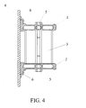
- Figure 4 shows an alternative embodiment of the sidewall construction according to the present invention, comprising a support construction formed of aluminium profiles 1, 2 and 3 and coarse threaded bolts 5, and a mold surface plate 4 fixed to the support construction.
- the mold surface plate 4 is formed of a metal plate like steel plate, having clamps 6 attached e.g. by welding for fixing the support construction. As shown in the figure, said clamps 6 form grooves to the back wall of the mold surface plate 4, where the protrusions formed to the edges of the upper and lower horizontal aluminium profile 1 and 2 set, said edges setting against the back wall of the mold surface plate 4.
- Figure 5 shows an alternative embodiment of the sidewall construction according to the invention, comprising a support construction formed of aluminium profiles 1, 2 and 3 and of coarse threaded bolts 5, and a mold surface plate 4 fixed to the support construction.
- the mold surface plate 4 is formed of a metal sheet having its ends bent towards the back wall of the mold surface plate, whereby grooves are formed to the upper and lower edges of the mold surface plate for the protrusions of the upper and lower horizontal aluminium profiles 1 and 2.
- the bends can also be formed advantageously to the mold surface plate 4 so that the mold surface plate will be strained between the tongues of the horizontal aluminium profiles 1 and 2, thus securing that the mold surface plate 4 will be correctly positioned and kept in place.
- the mold surface plate 4 keeps thus its form better during the cast.
- Figure 5 also shows an example of fixing the sidewall construction of a casting mold according to the invention onto a casting bed.
- the magnet unit 7 is positioned with respect to the sidewall construction so that the part of the lower horizontal aluminium profile 2 extending outwards from the mold surface, sets itself inside the magnet unit as shown in the figure.
- the fixed attachment of the magnet unit 7 to the sidewall construction will be secured by means of a driving pin 8 adjusted to go to the lower horizontal aluminium profile 2 through a hole formed thereto.
- Patent application FI 20060060 This kind of a magnet unit is described in Patent application FI 20060060 .
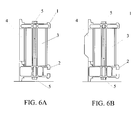
- the horizontal aluminium profiles 1 and 2 form with their edge surfaces a part of the mold surface that defines the product to be cast.
- the mold surface plate 4 is interposed between the upper horizontal aluminium profile 1 and the lower horizontal aluminium profile 2 so that the mold surface plate 4 is supported with its back surface on the vertical aluminium profile 3.
- Fig. 6B it is possible with this kind of a solution to shape the surface of the concrete product to be cast defined against the sidewall construction according to the invention.
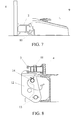
- Figure 7 shows one way of fixing the casting mold in accordance with the invention to the casting bed by means of a magnet unit disclosed in the publication EP-A-1 075 917 .
- a magnet unit disclosed in the publication EP-A-1 075 917 .
- the lower horizontal aluminium profile 2 with the mold surface plate 4 attached thereto are shown, being the most essential components of the sidewall construction from the point of view of this fixing solution.
- a connecting part 10 is placed in interlocking to the outer end of the lower horizontal aluminium profile 2, thus forming a connecting surface with a groove for the magnet unit 9.
- a bolt connection can be used, if necessary, for improving the attachment of the connecting part 10 to the aluminium profile 2.
- Figure 8 shows one way for fixing the sidewall construction according to the invention to the edge of the casting bed.
- the lower horizontal aluminium profile 2 with the mold surface plate 4 attached thereto are shown, being the most essential components of the sidewall construction from the point of view of this fixing solution.
- the sidewall construction of the casting mold is fixed with a fixing bolt 11 to a hinge part 12 being through pin 13 pivotably fixed to the edge of the casting bed.
- the hinge part is locked in place with a detachable locking pin 14.
- the hinge part 12 together with the sidewall construction can be turned outwards from the casting bed, whereby the cast product can be removed from the casting bed.
- the vertical position of the horizontal aluminium profiles 1 and 2 can be changed, as necessary, so that they can be placed in optimal positions, e.g. for positioning the reinforcing steels of the product to be cast, said steels eventually penetrating the mold surface plates of the casting mold 4, in a desired way to the casting mold.
- the sidewall construction according to the invention provides a lightweight sidewall construction having a simple construction to be used for casting concrete elements, said sidewall construction being easily cleanable and detachable from the casting bed.
- the solution according to the invention provides a simple solution for converting the sidewall construction as necessary, when casting short production runs.
- the sidewall construction according to the invention is in terms of support construction not limited to two vertical aluminium profiles connecting horizontal aluminium profiles. Based on the requirements set to the sidewall construction, the sidewall construction according to the invention can also be implemented, when necessary, with one vertical aluminium profile, or correspondingly, especially with long sidewall construction, more than two vertical aluminium profiles can be used, when necessary.
Landscapes
- Engineering & Computer Science (AREA)
- Manufacturing & Machinery (AREA)
- Chemical & Material Sciences (AREA)
- Ceramic Engineering (AREA)
- Mechanical Engineering (AREA)
- Forms Removed On Construction Sites Or Auxiliary Members Thereof (AREA)
- Details Of Indoor Wiring (AREA)
- Road Signs Or Road Markings (AREA)
- Sewage (AREA)
Claims (5)
- Seitenwandkonstruktion zum Gießen von Betonelementen, wobei die Seitenwandkonstruktion eine Formoberflächenplatte (4), die die Oberfläche des zu gießenden Produkts definiert, und eine Tragkonstruktion (1, 2, 3) umfasst, an der die Formoberflächenplatte abnehmbar befestigt ist, und wobei die Seitenwandkonstruktion an dem Gießbett mittels Magneten (7, 9) befestigt ist,
wobei die Tragkonstruktion, wenn sie an einem Gießbett befestigt ist, aus zwei horizontalen Aluminiumprofilen (1, 2) und aus zumindest einem vertikalen Aluminiumprofil (3) gebildet ist, das zwischen den horizontalen Aluminiumprofilen angeordnet ist und die horizontalen Profile verbindet, und dass das zumindest eine vertikale Aluminiumprofil an den horizontalen Aluminiumprofilen mittels Grobgewindebolzen oder -schrauben (5) befestigt ist. - Seitenwandkonstruktion einer Gussform nach Anspruch 1,
dadurch gekennzeichnet, dass zumindest zwei vertikale Aluminiumprofile (3) vorgesehen sind. - Seitenwandkonstruktion einer Gussform nach Anspruch 1 oder 2,
dadurch gekennzeichnet, dass die Formoberflächenplatte (4) an der Tragkonstruktion (1, 2, 3) durch formschlüssige Flächen befestigt ist. - Seitenwandkonstruktion einer Gussform nach Anspruch 1 oder 2,
dadurch gekennzeichnet, dass die Formoberflächenplatte (4) zwischen den horizontalen Aluminiumprofilen (1, 2) angeordnet ist. - Seitenwandkonstruktion einer Gussform nach einem der Ansprüche 1 bis 4,
dadurch gekennzeichnet, dass die Formoberflächenplatte (4) aus Holzwerkstoff, Kunststoff oder Metall hergestellt ist.
Applications Claiming Priority (1)
| Application Number | Priority Date | Filing Date | Title |
|---|---|---|---|
| FI20060816A FI126463B (fi) | 2006-09-13 | 2006-09-13 | Valumuotin laitarakenne |
Publications (3)
| Publication Number | Publication Date |
|---|---|
| EP1900489A2 EP1900489A2 (de) | 2008-03-19 |
| EP1900489A3 EP1900489A3 (de) | 2010-10-06 |
| EP1900489B1 true EP1900489B1 (de) | 2012-11-21 |
Family
ID=37067143
Family Applications (1)
| Application Number | Title | Priority Date | Filing Date |
|---|---|---|---|
| EP07397031A Active EP1900489B1 (de) | 2006-09-13 | 2007-09-10 | Seitenwandkonstruktion einer Gussform |
Country Status (7)
| Country | Link |
|---|---|
| US (1) | US7931250B2 (de) |
| EP (1) | EP1900489B1 (de) |
| AU (1) | AU2007214294B2 (de) |
| ES (1) | ES2400231T3 (de) |
| FI (1) | FI126463B (de) |
| NO (1) | NO337903B1 (de) |
| NZ (1) | NZ561108A (de) |
Cited By (1)
| Publication number | Priority date | Publication date | Assignee | Title |
|---|---|---|---|---|
| EP2821193A1 (de) | 2013-07-03 | 2015-01-07 | Elematic Oy Ab | Verfahren zur Einstellung einer Seitenwandeinheit und Seitenwandeinheit |
Families Citing this family (11)
| Publication number | Priority date | Publication date | Assignee | Title |
|---|---|---|---|---|
| EP2064030B1 (de) * | 2006-09-15 | 2013-05-22 | SRB Construction Technologies Pty Ltd. | Magnetklemmenanordnung |
| FI125405B (fi) * | 2008-04-29 | 2015-09-30 | Elematic Oyj | Valumuotin laitarakenne |
| FI20105685A7 (fi) * | 2010-06-15 | 2011-12-16 | Elematic Oy Ab | Valumuotin laitayksikkö sekä laitayksikön irrotusyksikkö |
| CN101852012A (zh) * | 2010-06-25 | 2010-10-06 | 山西惠丰型材有限公司 | 一种塑料清水混凝土建筑模板 |
| CN101922232A (zh) * | 2010-09-06 | 2010-12-22 | 常州市天绿塑业有限公司 | 塑料建筑模板 |
| CN103522399B (zh) * | 2013-10-31 | 2016-03-02 | 深圳海龙建筑制品有限公司 | 拼装可调的建筑预制件模具 |
| CH711101A2 (de) * | 2015-05-18 | 2016-11-30 | Airlight Energy Ip Sa | Verfahren zum Herstellen eines masshaltigen Betonwerkstücks und masshaltige Betonwerkstücke. |
| EP3403797A1 (de) * | 2017-05-18 | 2018-11-21 | RATEC Maschinenentwicklungs- und Verwaltungs-GmbH | Vorrichtung und system zum aufbau einer betonschalung |
| CN111761694B (zh) * | 2020-06-30 | 2021-08-13 | 五冶集团上海有限公司 | 一种适合预制混凝土梁产品生产的模板制作方法 |
| CN112727124A (zh) * | 2021-01-06 | 2021-04-30 | 中国化学工程第十一建设有限公司 | 地脚螺栓预埋定位模具及地脚螺栓安装方法 |
| CN113863653A (zh) * | 2021-09-28 | 2021-12-31 | 北京怡泰盛达技术发展有限责任公司 | 一种建筑专用模板及制备方法 |
Family Cites Families (22)
| Publication number | Priority date | Publication date | Assignee | Title |
|---|---|---|---|---|
| US3385557A (en) | 1965-09-15 | 1968-05-28 | Robert D. Rambelle | Multi-purpose building member |
| US4254932A (en) * | 1979-09-04 | 1981-03-10 | James Durbin | Concrete wall forming system |
| DE3035691A1 (de) * | 1980-09-22 | 1982-05-06 | Kurt 2000 Hamburg Pätz | Halterung fuer stellbretter fuer die schuettung von beton fuer decken an bauten |
| DE3138686A1 (de) | 1981-09-29 | 1983-04-14 | Siemens AG, 1000 Berlin und 8000 München | Schalter fuer lichtleiter |
| DE3409452A1 (de) * | 1984-03-15 | 1985-09-26 | Dyckerhoff & Widmann AG, 8000 München | Verstellbare schalung fuer betonbauteile |
| AT390111B (de) * | 1984-11-16 | 1990-03-26 | Rund Stahl Bau Gmbh & Co | Schalung zur errichtung von baukoerpern aus gussfaehigen materialien, wie beispielsweise beton |
| US4709899A (en) * | 1985-10-28 | 1987-12-01 | Shimizu Construction Co., Ltd. | Climbing formwork apparatus for concrete placing |
| CA2006575C (en) * | 1989-12-22 | 1993-06-22 | Vittorio Spera | Prefabricated assembly for poured concrete forming structures |
| CA2013173A1 (en) | 1990-03-27 | 1991-09-27 | Stanley R. Sandwith | Reversible concrete formwork |
| FI88472C (fi) | 1990-06-18 | 1993-05-25 | Partek Concrete Oy Ab | Gjutform |
| DE4103775C2 (de) * | 1991-02-08 | 1993-10-21 | Maier G Paschal Werk | Schaltafel mit an ihren Rändern abstehenden Randstegen aus Flachmaterial |
| DE4237595C2 (de) * | 1992-11-06 | 1994-10-20 | Oesterr Doka Schalung | Vorrichtung zum Abstützen eines senkrecht zur Längsachse eines Schalungsträgers verlaufenden Schalungselements |
| US5398909A (en) * | 1993-09-13 | 1995-03-21 | Channel Form Systems Inc. | Channel beam and T-bolt system |
| DE4412753A1 (de) | 1994-04-13 | 1995-10-19 | Peri Gmbh | Metallisches Hohlprofil von Schalelementen |
| NO954164L (no) * | 1994-11-11 | 1996-05-13 | Atle Laland | Forskalingsramme |
| AUPO649897A0 (en) * | 1997-04-28 | 1997-05-29 | A.R. Tiltwall Services | Method and arrangement for forming construction panels and structures |
| FI3487U1 (fi) * | 1998-03-27 | 1998-07-23 | Addtek Res & Dev Oy Ab | Valumuotin irrotettava laitajärjestelmä |
| FI4258U1 (fi) * | 1999-08-09 | 1999-12-15 | Addtek Res & Dev Oy Ab | Valumuotin irrotettava laitajärjestelmä |
| US7584540B2 (en) * | 1999-12-22 | 2009-09-08 | Ronald Lindsay Dunlop | Method of constructing formwork and an element for casting concrete components |
| US6550215B1 (en) * | 2000-06-28 | 2003-04-22 | Pn Ii, Inc. | Precast concrete wall system |
| NZ508434A (en) | 2000-11-28 | 2002-03-01 | Brian John Payne | Adjustable and reusable forming system for concrete floors or foundations |
| US20050116131A1 (en) | 2001-04-02 | 2005-06-02 | Michael Samuel | Support device |
-
2006
- 2006-09-13 FI FI20060816A patent/FI126463B/fi not_active IP Right Cessation
-
2007
- 2007-08-27 US US11/892,795 patent/US7931250B2/en not_active Expired - Fee Related
- 2007-08-29 AU AU2007214294A patent/AU2007214294B2/en not_active Ceased
- 2007-08-31 NZ NZ561108A patent/NZ561108A/en not_active IP Right Cessation
- 2007-09-06 NO NO20074507A patent/NO337903B1/no not_active IP Right Cessation
- 2007-09-10 ES ES07397031T patent/ES2400231T3/es active Active
- 2007-09-10 EP EP07397031A patent/EP1900489B1/de active Active
Cited By (1)
| Publication number | Priority date | Publication date | Assignee | Title |
|---|---|---|---|---|
| EP2821193A1 (de) | 2013-07-03 | 2015-01-07 | Elematic Oy Ab | Verfahren zur Einstellung einer Seitenwandeinheit und Seitenwandeinheit |
Also Published As
| Publication number | Publication date |
|---|---|
| NZ561108A (en) | 2009-03-31 |
| FI20060816L (fi) | 2008-03-14 |
| US7931250B2 (en) | 2011-04-26 |
| US20080315067A1 (en) | 2008-12-25 |
| EP1900489A2 (de) | 2008-03-19 |
| FI126463B (fi) | 2016-12-30 |
| AU2007214294A1 (en) | 2008-04-03 |
| FI20060816A0 (fi) | 2006-09-13 |
| ES2400231T3 (es) | 2013-04-08 |
| EP1900489A3 (de) | 2010-10-06 |
| AU2007214294B2 (en) | 2011-07-28 |
| NO20074507L (no) | 2008-03-14 |
| NO337903B1 (no) | 2016-07-04 |
Similar Documents
| Publication | Publication Date | Title |
|---|---|---|
| EP1900489B1 (de) | Seitenwandkonstruktion einer Gussform | |
| US6276657B1 (en) | Removable side wall system for a casting mould | |
| US5956922A (en) | Wall forming system and method of forming a wall of hardenable material | |
| EP1810806A2 (de) | Seitenwandanordnung für eine Giessform und eine Befestigungseinheit | |
| EP2113353B1 (de) | Seitenwandkonstruktion einer Gussform | |
| WO2003058008A1 (en) | Method and apparatus for forming construction panels and structures | |
| KR101095933B1 (ko) | 거푸집 고정용 거치대 | |
| KR20100102798A (ko) | 건축부자재 설치용 브라켓 | |
| KR200303750Y1 (ko) | 건축물 축조용 거푸집 보강대의 클램프 | |
| EP1114904A1 (de) | Befestigungskonstruktion und Installationsverfahren | |
| EP2641713B1 (de) | Betongussformsystem | |
| KR200420504Y1 (ko) | 거푸집 지지장치 | |
| WO2008135636A1 (en) | Method and apparatus for constructing a footing mould | |
| JP2778023B2 (ja) | 笠コンクリート用型枠 | |
| JPH0236844Y2 (de) | ||
| KR200448795Y1 (ko) | 거푸집 드럽헤드 | |
| AU2005203150A1 (en) | Formwork arrangement | |
| JP2001081967A (ja) | 型枠吊り金具 | |
| IL295429B1 (en) | Casting mold | |
| KR200448791Y1 (ko) | 거푸집 해체장치의 상판상하강장치 | |
| KR200447082Y1 (ko) | 거푸집 데스크빔 고정장치 | |
| JP2022140972A (ja) | べた基礎のコンクリート一体打ち施工方法 | |
| KR20000004214U (ko) | 거푸집용 수평조절대 | |
| JPH07158269A (ja) | 型枠装置 | |
| JPH0585939U (ja) | スラブ工事型枠受け金物 |
Legal Events
| Date | Code | Title | Description |
|---|---|---|---|
| PUAI | Public reference made under article 153(3) epc to a published international application that has entered the european phase |
Free format text: ORIGINAL CODE: 0009012 |
|
| AK | Designated contracting states |
Kind code of ref document: A2 Designated state(s): AT BE BG CH CY CZ DE DK EE ES FI FR GB GR HU IE IS IT LI LT LU LV MC MT NL PL PT RO SE SI SK TR |
|
| AX | Request for extension of the european patent |
Extension state: AL BA HR MK YU |
|
| PUAL | Search report despatched |
Free format text: ORIGINAL CODE: 0009013 |
|
| AK | Designated contracting states |
Kind code of ref document: A3 Designated state(s): AT BE BG CH CY CZ DE DK EE ES FI FR GB GR HU IE IS IT LI LT LU LV MC MT NL PL PT RO SE SI SK TR |
|
| AX | Request for extension of the european patent |
Extension state: AL BA HR MK RS |
|
| RIC1 | Information provided on ipc code assigned before grant |
Ipc: B28B 7/00 20060101AFI20080102BHEP Ipc: E04G 11/50 20060101ALI20100830BHEP |
|
| 17P | Request for examination filed |
Effective date: 20110311 |
|
| AKX | Designation fees paid |
Designated state(s): AT BE BG CH CY CZ DE DK EE ES FI FR GB GR HU IE IS IT LI LT LU LV MC MT NL PL PT RO SE SI SK TR |
|
| 17Q | First examination report despatched |
Effective date: 20110909 |
|
| GRAC | Information related to communication of intention to grant a patent modified |
Free format text: ORIGINAL CODE: EPIDOSCIGR1 |
|
| GRAP | Despatch of communication of intention to grant a patent |
Free format text: ORIGINAL CODE: EPIDOSNIGR1 |
|
| RAP1 | Party data changed (applicant data changed or rights of an application transferred) |
Owner name: PCE TECHNOLOGIES OY |
|
| GRAS | Grant fee paid |
Free format text: ORIGINAL CODE: EPIDOSNIGR3 |
|
| GRAA | (expected) grant |
Free format text: ORIGINAL CODE: 0009210 |
|
| RAP1 | Party data changed (applicant data changed or rights of an application transferred) |
Owner name: ELEMATIC OY AB |
|
| AK | Designated contracting states |
Kind code of ref document: B1 Designated state(s): AT BE BG CH CY CZ DE DK EE ES FI FR GB GR HU IE IS IT LI LT LU LV MC MT NL PL PT RO SE SI SK TR |
|
| REG | Reference to a national code |
Ref country code: GB Ref legal event code: FG4D |
|
| REG | Reference to a national code |
Ref country code: CH Ref legal event code: EP |
|
| REG | Reference to a national code |
Ref country code: AT Ref legal event code: REF Ref document number: 584807 Country of ref document: AT Kind code of ref document: T Effective date: 20121215 |
|
| REG | Reference to a national code |
Ref country code: IE Ref legal event code: FG4D |
|
| REG | Reference to a national code |
Ref country code: DE Ref legal event code: R096 Ref document number: 602007026810 Country of ref document: DE Effective date: 20130117 |
|
| REG | Reference to a national code |
Ref country code: NL Ref legal event code: T3 |
|
| REG | Reference to a national code |
Ref country code: ES Ref legal event code: FG2A Ref document number: 2400231 Country of ref document: ES Kind code of ref document: T3 Effective date: 20130408 |
|
| REG | Reference to a national code |
Ref country code: AT Ref legal event code: MK05 Ref document number: 584807 Country of ref document: AT Kind code of ref document: T Effective date: 20121121 |
|
| REG | Reference to a national code |
Ref country code: LT Ref legal event code: MG4D |
|
| PG25 | Lapsed in a contracting state [announced via postgrant information from national office to epo] |
Ref country code: FI Free format text: LAPSE BECAUSE OF FAILURE TO SUBMIT A TRANSLATION OF THE DESCRIPTION OR TO PAY THE FEE WITHIN THE PRESCRIBED TIME-LIMIT Effective date: 20121121 Ref country code: LT Free format text: LAPSE BECAUSE OF FAILURE TO SUBMIT A TRANSLATION OF THE DESCRIPTION OR TO PAY THE FEE WITHIN THE PRESCRIBED TIME-LIMIT Effective date: 20121121 Ref country code: SE Free format text: LAPSE BECAUSE OF FAILURE TO SUBMIT A TRANSLATION OF THE DESCRIPTION OR TO PAY THE FEE WITHIN THE PRESCRIBED TIME-LIMIT Effective date: 20121121 |
|
| PG25 | Lapsed in a contracting state [announced via postgrant information from national office to epo] |
Ref country code: PT Free format text: LAPSE BECAUSE OF FAILURE TO SUBMIT A TRANSLATION OF THE DESCRIPTION OR TO PAY THE FEE WITHIN THE PRESCRIBED TIME-LIMIT Effective date: 20130321 Ref country code: SI Free format text: LAPSE BECAUSE OF FAILURE TO SUBMIT A TRANSLATION OF THE DESCRIPTION OR TO PAY THE FEE WITHIN THE PRESCRIBED TIME-LIMIT Effective date: 20121121 Ref country code: PL Free format text: LAPSE BECAUSE OF FAILURE TO SUBMIT A TRANSLATION OF THE DESCRIPTION OR TO PAY THE FEE WITHIN THE PRESCRIBED TIME-LIMIT Effective date: 20121121 Ref country code: GR Free format text: LAPSE BECAUSE OF FAILURE TO SUBMIT A TRANSLATION OF THE DESCRIPTION OR TO PAY THE FEE WITHIN THE PRESCRIBED TIME-LIMIT Effective date: 20130222 Ref country code: LV Free format text: LAPSE BECAUSE OF FAILURE TO SUBMIT A TRANSLATION OF THE DESCRIPTION OR TO PAY THE FEE WITHIN THE PRESCRIBED TIME-LIMIT Effective date: 20121121 |
|
| PG25 | Lapsed in a contracting state [announced via postgrant information from national office to epo] |
Ref country code: AT Free format text: LAPSE BECAUSE OF FAILURE TO SUBMIT A TRANSLATION OF THE DESCRIPTION OR TO PAY THE FEE WITHIN THE PRESCRIBED TIME-LIMIT Effective date: 20121121 |
|
| PG25 | Lapsed in a contracting state [announced via postgrant information from national office to epo] |
Ref country code: BG Free format text: LAPSE BECAUSE OF FAILURE TO SUBMIT A TRANSLATION OF THE DESCRIPTION OR TO PAY THE FEE WITHIN THE PRESCRIBED TIME-LIMIT Effective date: 20130221 Ref country code: DK Free format text: LAPSE BECAUSE OF FAILURE TO SUBMIT A TRANSLATION OF THE DESCRIPTION OR TO PAY THE FEE WITHIN THE PRESCRIBED TIME-LIMIT Effective date: 20121121 Ref country code: CZ Free format text: LAPSE BECAUSE OF FAILURE TO SUBMIT A TRANSLATION OF THE DESCRIPTION OR TO PAY THE FEE WITHIN THE PRESCRIBED TIME-LIMIT Effective date: 20121121 Ref country code: SK Free format text: LAPSE BECAUSE OF FAILURE TO SUBMIT A TRANSLATION OF THE DESCRIPTION OR TO PAY THE FEE WITHIN THE PRESCRIBED TIME-LIMIT Effective date: 20121121 Ref country code: EE Free format text: LAPSE BECAUSE OF FAILURE TO SUBMIT A TRANSLATION OF THE DESCRIPTION OR TO PAY THE FEE WITHIN THE PRESCRIBED TIME-LIMIT Effective date: 20121121 |
|
| PG25 | Lapsed in a contracting state [announced via postgrant information from national office to epo] |
Ref country code: RO Free format text: LAPSE BECAUSE OF FAILURE TO SUBMIT A TRANSLATION OF THE DESCRIPTION OR TO PAY THE FEE WITHIN THE PRESCRIBED TIME-LIMIT Effective date: 20121121 |
|
| PLBE | No opposition filed within time limit |
Free format text: ORIGINAL CODE: 0009261 |
|
| STAA | Information on the status of an ep patent application or granted ep patent |
Free format text: STATUS: NO OPPOSITION FILED WITHIN TIME LIMIT |
|
| 26N | No opposition filed |
Effective date: 20130822 |
|
| REG | Reference to a national code |
Ref country code: DE Ref legal event code: R097 Ref document number: 602007026810 Country of ref document: DE Effective date: 20130822 |
|
| PG25 | Lapsed in a contracting state [announced via postgrant information from national office to epo] |
Ref country code: MC Free format text: LAPSE BECAUSE OF FAILURE TO SUBMIT A TRANSLATION OF THE DESCRIPTION OR TO PAY THE FEE WITHIN THE PRESCRIBED TIME-LIMIT Effective date: 20121121 |
|
| REG | Reference to a national code |
Ref country code: CH Ref legal event code: PL |
|
| REG | Reference to a national code |
Ref country code: IE Ref legal event code: MM4A |
|
| PG25 | Lapsed in a contracting state [announced via postgrant information from national office to epo] |
Ref country code: IE Free format text: LAPSE BECAUSE OF NON-PAYMENT OF DUE FEES Effective date: 20130910 Ref country code: LI Free format text: LAPSE BECAUSE OF NON-PAYMENT OF DUE FEES Effective date: 20130930 Ref country code: CH Free format text: LAPSE BECAUSE OF NON-PAYMENT OF DUE FEES Effective date: 20130930 |
|
| PG25 | Lapsed in a contracting state [announced via postgrant information from national office to epo] |
Ref country code: TR Free format text: LAPSE BECAUSE OF FAILURE TO SUBMIT A TRANSLATION OF THE DESCRIPTION OR TO PAY THE FEE WITHIN THE PRESCRIBED TIME-LIMIT Effective date: 20121121 Ref country code: MT Free format text: LAPSE BECAUSE OF FAILURE TO SUBMIT A TRANSLATION OF THE DESCRIPTION OR TO PAY THE FEE WITHIN THE PRESCRIBED TIME-LIMIT Effective date: 20121121 Ref country code: CY Free format text: LAPSE BECAUSE OF FAILURE TO SUBMIT A TRANSLATION OF THE DESCRIPTION OR TO PAY THE FEE WITHIN THE PRESCRIBED TIME-LIMIT Effective date: 20121121 |
|
| PG25 | Lapsed in a contracting state [announced via postgrant information from national office to epo] |
Ref country code: HU Free format text: LAPSE BECAUSE OF FAILURE TO SUBMIT A TRANSLATION OF THE DESCRIPTION OR TO PAY THE FEE WITHIN THE PRESCRIBED TIME-LIMIT; INVALID AB INITIO Effective date: 20070910 Ref country code: LU Free format text: LAPSE BECAUSE OF NON-PAYMENT OF DUE FEES Effective date: 20130910 |
|
| PG25 | Lapsed in a contracting state [announced via postgrant information from national office to epo] |
Ref country code: IS Free format text: LAPSE BECAUSE OF FAILURE TO SUBMIT A TRANSLATION OF THE DESCRIPTION OR TO PAY THE FEE WITHIN THE PRESCRIBED TIME-LIMIT Effective date: 20121121 |
|
| REG | Reference to a national code |
Ref country code: FR Ref legal event code: PLFP Year of fee payment: 10 |
|
| REG | Reference to a national code |
Ref country code: FR Ref legal event code: PLFP Year of fee payment: 11 |
|
| REG | Reference to a national code |
Ref country code: FR Ref legal event code: PLFP Year of fee payment: 12 |
|
| PGFP | Annual fee paid to national office [announced via postgrant information from national office to epo] |
Ref country code: IT Payment date: 20190925 Year of fee payment: 13 Ref country code: NL Payment date: 20190918 Year of fee payment: 13 Ref country code: FR Payment date: 20190926 Year of fee payment: 13 |
|
| PGFP | Annual fee paid to national office [announced via postgrant information from national office to epo] |
Ref country code: BE Payment date: 20190918 Year of fee payment: 13 |
|
| PGFP | Annual fee paid to national office [announced via postgrant information from national office to epo] |
Ref country code: GB Payment date: 20190925 Year of fee payment: 13 |
|
| PGFP | Annual fee paid to national office [announced via postgrant information from national office to epo] |
Ref country code: ES Payment date: 20191022 Year of fee payment: 13 |
|
| REG | Reference to a national code |
Ref country code: NL Ref legal event code: MM Effective date: 20201001 |
|
| GBPC | Gb: european patent ceased through non-payment of renewal fee |
Effective date: 20200910 |
|
| REG | Reference to a national code |
Ref country code: BE Ref legal event code: MM Effective date: 20200930 |
|
| PG25 | Lapsed in a contracting state [announced via postgrant information from national office to epo] |
Ref country code: NL Free format text: LAPSE BECAUSE OF NON-PAYMENT OF DUE FEES Effective date: 20201001 |
|
| PG25 | Lapsed in a contracting state [announced via postgrant information from national office to epo] |
Ref country code: FR Free format text: LAPSE BECAUSE OF NON-PAYMENT OF DUE FEES Effective date: 20200930 |
|
| PG25 | Lapsed in a contracting state [announced via postgrant information from national office to epo] |
Ref country code: GB Free format text: LAPSE BECAUSE OF NON-PAYMENT OF DUE FEES Effective date: 20200910 Ref country code: BE Free format text: LAPSE BECAUSE OF NON-PAYMENT OF DUE FEES Effective date: 20200930 |
|
| PG25 | Lapsed in a contracting state [announced via postgrant information from national office to epo] |
Ref country code: IT Free format text: LAPSE BECAUSE OF NON-PAYMENT OF DUE FEES Effective date: 20200910 |
|
| REG | Reference to a national code |
Ref country code: ES Ref legal event code: FD2A Effective date: 20220117 |
|
| PG25 | Lapsed in a contracting state [announced via postgrant information from national office to epo] |
Ref country code: ES Free format text: LAPSE BECAUSE OF NON-PAYMENT OF DUE FEES Effective date: 20200911 |
|
| PGFP | Annual fee paid to national office [announced via postgrant information from national office to epo] |
Ref country code: DE Payment date: 20250919 Year of fee payment: 19 |