EP1897185B1 - Terminal feeding device for a termination machine - Google Patents
Terminal feeding device for a termination machine Download PDFInfo
- Publication number
- EP1897185B1 EP1897185B1 EP06785677.3A EP06785677A EP1897185B1 EP 1897185 B1 EP1897185 B1 EP 1897185B1 EP 06785677 A EP06785677 A EP 06785677A EP 1897185 B1 EP1897185 B1 EP 1897185B1
- Authority
- EP
- European Patent Office
- Prior art keywords
- feeder
- termination
- terminal
- carriage
- actuator
- Prior art date
- Legal status (The legal status is an assumption and is not a legal conclusion. Google has not performed a legal analysis and makes no representation as to the accuracy of the status listed.)
- Not-in-force
Links
Images


Classifications
-
- H—ELECTRICITY
- H01—ELECTRIC ELEMENTS
- H01R—ELECTRICALLY-CONDUCTIVE CONNECTIONS; STRUCTURAL ASSOCIATIONS OF A PLURALITY OF MUTUALLY-INSULATED ELECTRICAL CONNECTING ELEMENTS; COUPLING DEVICES; CURRENT COLLECTORS
- H01R43/00—Apparatus or processes specially adapted for manufacturing, assembling, maintaining, or repairing of line connectors or current collectors or for joining electric conductors
- H01R43/04—Apparatus or processes specially adapted for manufacturing, assembling, maintaining, or repairing of line connectors or current collectors or for joining electric conductors for forming connections by deformation, e.g. crimping tool
- H01R43/048—Crimping apparatus or processes
- H01R43/055—Crimping apparatus or processes with contact member feeding mechanism
-
- B—PERFORMING OPERATIONS; TRANSPORTING
- B23—MACHINE TOOLS; METAL-WORKING NOT OTHERWISE PROVIDED FOR
- B23P—METAL-WORKING NOT OTHERWISE PROVIDED FOR; COMBINED OPERATIONS; UNIVERSAL MACHINE TOOLS
- B23P19/00—Machines for simply fitting together or separating metal parts or objects, or metal and non-metal parts, whether or not involving some deformation; Tools or devices therefor so far as not provided for in other classes
-
- H—ELECTRICITY
- H01—ELECTRIC ELEMENTS
- H01R—ELECTRICALLY-CONDUCTIVE CONNECTIONS; STRUCTURAL ASSOCIATIONS OF A PLURALITY OF MUTUALLY-INSULATED ELECTRICAL CONNECTING ELEMENTS; COUPLING DEVICES; CURRENT COLLECTORS
- H01R43/00—Apparatus or processes specially adapted for manufacturing, assembling, maintaining, or repairing of line connectors or current collectors or for joining electric conductors
- H01R43/04—Apparatus or processes specially adapted for manufacturing, assembling, maintaining, or repairing of line connectors or current collectors or for joining electric conductors for forming connections by deformation, e.g. crimping tool
- H01R43/042—Hand tools for crimping
-
- Y—GENERAL TAGGING OF NEW TECHNOLOGICAL DEVELOPMENTS; GENERAL TAGGING OF CROSS-SECTIONAL TECHNOLOGIES SPANNING OVER SEVERAL SECTIONS OF THE IPC; TECHNICAL SUBJECTS COVERED BY FORMER USPC CROSS-REFERENCE ART COLLECTIONS [XRACs] AND DIGESTS
- Y10—TECHNICAL SUBJECTS COVERED BY FORMER USPC
- Y10T—TECHNICAL SUBJECTS COVERED BY FORMER US CLASSIFICATION
- Y10T29/00—Metal working
- Y10T29/49—Method of mechanical manufacture
- Y10T29/49002—Electrical device making
- Y10T29/49117—Conductor or circuit manufacturing
- Y10T29/49174—Assembling terminal to elongated conductor
-
- Y—GENERAL TAGGING OF NEW TECHNOLOGICAL DEVELOPMENTS; GENERAL TAGGING OF CROSS-SECTIONAL TECHNOLOGIES SPANNING OVER SEVERAL SECTIONS OF THE IPC; TECHNICAL SUBJECTS COVERED BY FORMER USPC CROSS-REFERENCE ART COLLECTIONS [XRACs] AND DIGESTS
- Y10—TECHNICAL SUBJECTS COVERED BY FORMER USPC
- Y10T—TECHNICAL SUBJECTS COVERED BY FORMER US CLASSIFICATION
- Y10T29/00—Metal working
- Y10T29/53—Means to assemble or disassemble
- Y10T29/5313—Means to assemble electrical device
- Y10T29/532—Conductor
- Y10T29/53209—Terminal or connector
- Y10T29/53213—Assembled to wire-type conductor
Definitions
- This invention relates to terminal crimping machines, and more specifically, to motor controlled feeder devices for terminal crimping machines.
- Figure 1 illustrates a perspective view of a termination machine or terminator 100 having a termination tool 102 with terminating tooling and a feeder device 104.
- the terminator 100 is illustrated as a terminal crimping machine used for crimping connectors to wires, however, other types of terminators 100 may be used, such as, an IDC machine, a welding machine, and the like that attach connectors to wires using processes other than crimping, or the terminator 100 may be another type of crimping machine such as a lead frame machine.
- the termination tool 102 is illustrated and described hereinafter as an applicator 102.
- the applicator 102 is coupled to a frame 105 of the terminator 100.
- the applicator 102 may be removed and replaced with a different applicator, such as when the applicator 102 is worn or damaged or when an applicator having a different configuration is desired.
- the applicator 102 has a terminating zone or crimping zone 106 and includes crimp-tooling 108 for crimping electrical connectors or terminals 110 to an end of a wire 112 in the crimping zone 106.
- the feeder device 104 is positioned to feed terminals accurately to the applicator 102 and presents the terminals 110 to the crimping zone 106.
- the feeder device 104 may be positioned adjacent to, or even coupled to, the applicator 102.
- the feeder device 104 may be positioned remote with respect to the applicator 102, but still delivers the terminals 110 to the crimping zone 106.
- the terminals 110 may be guided to the crimp zone 106 by a guide member (not shown) to ensure proper positioning of the terminals 110 within the crimping zone 106.
- the wires 112 are delivered to the crimping zone 106 by a wire feeder (not shown) or a bench machine (not shown) in a wire loading direction 114.
- the feeder device 104 may be configured to deliver, and the applicator 102 may be configured to receive, multiple sized terminals for crimping.
- the feeder device 104 may be configured to deliver either side-feed terminals or end-feed terminals.
- Side-feed terminals are arranged side-by-side on a carrier strip and end-feed terminals are arranged successively, end-to-end.
- the terminator 100 is configured to receive applicators 102 for either type of terminal, namely the side-feed or the end-feed terminals.
- a first type of applicator 102 may be configured to receive side-feed terminals and a second type of applicator 102 may be configured to receive end-feed terminals.
- the side-feed and end feed types of applicators 102 may be interchanged with the terminator 100.
- a side-feed type applicator 102 is illustrated in Figure 1 .
- the crimp-tooling 108 is driven through a crimp stroke by a driving mechanism 116 of the terminator 100 toward a stationary anvil 118.
- the crimp stroke has both a downward component and an upward component.
- the crimping of the terminal 110 to the wire 112 occurs during the downward component of the crimp stroke.
- the driving mechanism 116 is driven by a terminator actuator 120.
- the terminator actuator 120 may be a motor having a drive shaft that moves driving mechanism 116.
- the terminator actuator 120 may be a linear actuator, a piezoelectric actuator, and the like.
- the operation of the terminator actuator 120 is controlled by a control module 122.
- Figure 2 illustrates a perspective view of a side-feed type applicator 102 and the feeder device 104.
- the feeder device 104 is positioned adjacent to the applicator 102 and presents side-feed terminals 110 to the crimping zone 106 of the applicator 102.
- Figure 3 illustrates a perspective view of an end-feed type applicator 102A and the feeder device 104.
- the applicator 102A is similar to the applicator 102 shown in Figure 2 . As such, like reference numerals are used to identify like features.
- the applicator 102 includes a frame 130 having a base 132.
- the anvil 118 is coupled to the base 132.
- the frame 130 includes a front 134, a rear 136, a side 138, a side 140, and a central cavity 142.
- the feeder device 104 is positioned adjacent to the rear 136 and the terminals 110 are carried or advanced in a feed direction from the rear 136 toward the front 134, such as in the feed direction of arrow A.
- the terminals 110 may be presented along the side 138.
- the sides 138 and 140 extend generally parallel to the feed direction of the terminals 110.
- a ram 144 is received within the central cavity 142 and is movable with respect to the frame 130.
- the crimp-tooling 108 is coupled to the ram 144 and is positioned adjacent to the side 138.
- the ram 144 is coupled to the driving mechanism 116 (shown in Figure 1 ) of the terminator 100 (shown in Figure 1 ).
- the driving mechanism 116 moves the ram 144 vertically in a lifting or reset direction, shown by arrow B, generally away from the anvil 118 and a crimping direction, shown by arrow C, generally toward the anvil 118.
- the feeding of the terminals 110 and the driving of the ram 144 are coordinated. For example, as the ram 144 is moved in the lifting direction, the terminals 110 are advanced in the feed direction by the feeder device 104.
- the terminals 110 may also be advanced while the ram 144 is moved in the crimping direction.
- the terminals 110 are located in the crimping zone 106 and are stationary as the crimp-tooling nears the crimping zone 106.
- the feeder device 104 is positioned adjacent to the applicator 102A and presents end-feed terminals 110A to the crimping zone 106 of the applicator 102A.
- the end-feed terminals are stacked end-to-end and fed to a central portion of the rear 136 of the applicator 102A, generally equidistant from the sides 138 and 140.
- the crimp-tooling 108 is also centrally located between the sides 138 and 140.
- FIG 4 illustrates a perspective view of the feeder device 104 with a cover 160 removed.
- the feeder device 104 may be separately provided from the applicator 102 (shown in Figures 1-3 ) and removably coupled to the applicator 102.
- the feeder device 104 may be permanently coupled to the applicator 102.
- the feeder device 104 may be coupled to a portion of the frame 105 (shown in Figure 1 ) of the terminator 100 (shown in Figure 1 ).
- the feeder device 104 includes a feeder actuator 200 joined to a lead screw 202 and a feeder carriage 204 also coupled to the lead screw 202.
- the feeder device 104 may include a ball screw or another type of driving mechanism in place of the lead screw 202.
- the feeder actuator 200 is a servo motor.
- the feeder actuator 200 may be a stepper motor, or another type of actuator such as, for example, a linear actuator, a piezoelectric actuator or motor, and the like.
- the feeder actuator 200 includes a controller 203 for controlling the operation of the feeder actuator 200.
- the controller 203 may communicate with the control module 122 (shown in Figure 1 ) to coordinate the operation of the feeder actuator 200 with the operation of the driving mechanism 116 (shown in Figure 1 ).
- the feeder actuator 200 may be joined to the control module 122 of the terminator 100 for controlling the operation of the feeder actuator 200.
- the feeder actuator 200 rotates the lead screw 202 about an axis of rotation 205, and the rotational motion of the lead screw 202 is transferred to linear motion of the feeder carriage 204.
- the feeder carriage 204 is moveable linearly between an advanced position, wherein the feeder carriage 204 is moved to a preset position in the direction of arrow D, and a retracted position, wherein the feeder carriage 204 is moved to a preset position in the direction of arrow E.
- the terminals 110 are positioned in the crimping zone 106.
- the feeder device 104 engages a new terminal for advancement.
- the feeder actuator 200 rotates the lead screw 202 in both a forward driving direction and a rearward driving direction.
- the feeder actuator 200 rotates the lead screw 202 in a clockwise direction, and in the rearward driving direction the feeder actuator 200 rotates the lead screw 202 in a counter-clockwise direction.
- the feeder actuator 200 rotates the lead screw 202 in a counter-clockwise direction, and in the rearward driving direction the feeder actuator 200 rotates the lead screw 202 in a clockwise direction.
- the feeder carriage 204 is moved in the direction of the advanced position.
- the feeder carriage 204 is moved in the direction of the retracted position.
- the amount of rotation of the lead screw 202 is controlled and may be programmable based on the particular application for the terminator 100, such as, for example, the size of the terminals 110 (shown in Figure 1 ) or the spacing of the terminals 110.
- the feeder device 104 may include a belt drive or a gear drive coupled between the feeder actuator 200 and the lead screw 202.
- the feeder carriage 204 may be rotated by the feeder actuator 200 to advance the terminals 110 to the crimping zone 106.
- the feeder device 104 includes a frame 206 having a front support plate 208 and a rear support plate 210.
- the front and rear support plates 208 and 210 are planar and extend parallel to one another.
- Each support plate 208 and 210 includes a front surface 212 and a rear surface 214.
- the rear support plate 210 supports the feeder actuator 200, and the feeder actuator 200 is positioned along a portion of the rear surface 214 of the rear support plate 210.
- the front support plate 208 supports a mounting bracket 216, and the mounting bracket 216 is positioned along the front surface 212 of the front support plate 208.
- the frame 206 includes a tube 220 extending between the front and rear support plates 208 and 210.
- the tube 220 may support the front and rear support plates 208 and 210 and maintain the spacing between the front and rear support plates 208 and 210.
- the tube 220 may also carry wires between the front and rear support plates 208 and 210, as will be described in more detail below.
- the feeder carriage 204 includes a body 230 having a front end 232, a rear end 234, a top end 236, a bottom end 238, and sides 240 extending between each of the ends.
- the feeder carriage 204 may be box-shaped.
- the feeder carriage 204 includes a plurality of openings extending therethrough, such as an upper guide opening 242, a lower guide opening 244, a lead screw opening (not shown), and a sensor device opening 246.
- the openings extend generally between the front end 232 and the rear end 234 of the body 230.
- the openings may be substantially aligned. In other embodiments, the openings may be off-set with respect to one another.
- the upper guide opening 242 receives an upper bushing 248 and the lower guide opening receives a lower bushing 250.
- the upper bushing 248 receives an upper guide rail 252 and the lower bushing 250 receives a lower guide rail 254.
- the upper and lower guide rails 252 and 254 are received in the gap 218 and extend between the front and rear support plates 208 and 210.
- the upper and lower guide rails 252 and 254 support the feeder carriage 204 and define a path of travel for the feeder carriage 204.
- the upper and lower guide rails 252 and 254 support the front and rear support plates 208 and 210 and maintain the spacing between the front and rear support plates 208 and 210.
- the feeder carriage 204 includes a lead screw nut 260 secured thereto.
- the lead screw nut 260 may be integrally formed with the feeder carriage body 230.
- the lead screw nut 260 is aligned with the lead screw opening and threadably engages the lead screw 202. Rotational motion of the lead screw 202 is transferred to linear motion of the feeder carriage 204 by the threaded relationship between the lead screw 202 and the lead screw nut 260.
- a feeding member assembly 270 is coupled to the feeder carriage 204 and carried by the feeder carriage 204 between the advanced position and the retracted position.
- the feeding member assembly 270 includes a mounting block 272 that is removably coupled to the side of the body 230 at the bottom end 238.
- the mounting block 272 may be coupled directly to the bottom end 238 and may be substantially centered with respect to the sides 240 of the body 230.
- the mounting block 272 may be substantially centered with respect to the body 230.
- the feeding member assembly 270 also includes a terminal feeding member 274 removably coupled to the mounting block 272.
- the terminal feeding member 274 includes a tip 276 configured to engage the terminals 110 or the carrier strip for the terminals 110.
- the feeder device 104 may include a sensor device 280 for determining the linear position of the feeder carriage 204.
- the sensor device includes a sensor arm 282 extending within the gap 218 and positioned adjacent to the feeder carriage to determine the relative position of the feeder carriage 204 with respect to the feeder actuator 200.
- the sensor arm 282 extends through the sensor device opening 246 of the body 230.
- the feeder carriage 204 is moveable along the sensor arm 282, and a signal representing the position of the feeder carriage 204 is transmitted to either the controller 203 for the feeder actuator 200 or to the control module 122 for the terminal crimping machine 100.
- the sensor device 280 thus provides feedback to the controller 203 for controlling the position of the feeder carriage 204.
- a closed loop feedback may be provided to the feeder device 104.
- the cover 160 extends over the components of the feeder device 104 such as the feeder actuator 200 and the feeder carriage 204.
- the cover 160 may be coupled to the front and rear support plates 208 and 210.
- the cover 160 includes a slot 284 in a bottom portion of the cover 160 to allow for linear movement of the feeder carriage 204.
- the feeding member assembly 270 extends below the cover 160 and is accessible from outside of the cover 160. The feeding member assembly 270 moves along the slot 284 during operation of the feeder device 104.
- other components of the feeder device 104 may be exposed outside the cover 160, such as the feeder actuator 200.
- FIG 5 illustrates a cross sectional view of the applicator 102 and the feeder device 104 taken generally along a plane extending through the sensor arm 282 shown in Figure 4 .
- the front and rear support plates 208 and 210 support the various components of the feeder device 104.
- the rear support plate 210 supports the feeder actuator 200.
- the rear support plate 210 includes a housing portion 300 defining a cavity 302.
- a shaft portion 304 of the feeder actuator 200 is received in the cavity 302.
- a coupler 306 is also received in the cavity 302 and directly couples the shaft portion 304 to the lead screw 202.
- an intervening linkage may be provided between the shaft portion 304 and the lead screw 202, such as gears.
- Bearings 308 are provided between the lead screw 202 and each of the front and rear support plates 208 and 210 to facilitate rotation of the lead screw 202.
- the bearings 308 are positioned proximate a forward end 310 and a rearward end 312 of the lead screw 202.
- bushings may be used in place of bearings 308.
- Figure 5 also illustrates the lead screw 202 extending through the lead screw opening, described above and now shown generally at 314.
- the lead screw nut 260 extends through the lead screw opening 314.
- the sensor device 280 is also illustrated as being supported by each of the front and rear support plates 208 and 210.
- the sensor arm 282 extends through the sensor device opening 246 in the body 230 of the feeder carriage 204 and interacts with a sensor 316 also received within the sensor device opening 246.
- the upper and lower guide rails 252 and 254 are supported by each of the front and rear support plates 208 and 210. Each guide rail 252 and 254 extends between a forward end 320 engaging the front support plate 208 and a rearward end 322 engaging the rear support plate 210. Optionally, the upper and lower guide rails 252 and 254 may be secured to the front and rear support plates 208 and 210 by fasteners such as screws.
- the upper and lower guide rails 252 and 254 also extend through the upper and lower bushings 248 and 250, respectively. The upper and lower bushings 248 and 250 slide along the upper and lower guide rails 252 and 254 during movement of the feeder carriage 104.
- FIG 6 illustrates a perspective view of the applicator 102 and the feeder device 104.
- the applicator 102 includes a mounting bracket 330 coupled to the rear 136 of the frame 130.
- the mounting bracket 216 of the feeder device 104 is removably coupled to the mounting bracket 330 of the applicator 102.
- the applicator 102 thus supports the feeder device 104 generally above the terminals 110 such that the terminal feeding member 274 of the feeding member assembly 270 may engage the terminals 110 or the carrier strip for the terminals 110.
- the feeder device 104 may be coupled to another portion of the terminator 100 (shown in Figure 1 ) such that applicators 102 may be interchanged in the terminator 100 without moving the feeder device 104.
- the feeder device 104 includes a release 332 to release or detach the feeder device 104 from the applicator 102 or the terminator 100.
- the cost of the applicator 102, and thus the terminator 100, may be reduced because a single feeder device 104 may be interchangeable with various applicators 102.
- the applicator 102 includes a memory device 334 coupled to the mounting bracket 330.
- the memory device 334 may include information, such as feeding parameters based on the type of applicator 102, relating to a feed stroke for the feeder device 104.
- the feeder device 104 may be configured to read the information from the memory device 334, or the information may be otherwise transmitted or transferred to the feeder device 104 to control the feed stroke and properly position the terminals 110 within the crimping zone 106.
- the feeder device 104 includes a reader/writer device 336 (shown in Figure 4 ) that reads the information from the memory device 334.
- the memory device 334 transmits the information to controller 203 via a wire (not shown) running through tube 220 (shown in Figure 4 ).
- the feeder device 104 may automatically adjust the feed stroke without a user's adjustment based on the information.
- the memory device 334 is a RAM-type memory device that is readable and writable by the controller 203.
- the memory device may be a radio frequency identification tag.
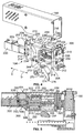
- FIG 7 illustrates the feeding member assembly 270 for the feeder device 104 (shown in Figures 1-6 ).
- the mounting block 272 extends between a mounting end 340 and a mating end 342 and includes opposed side surfaces 344 and 346.
- the mounting end 340 is configured to be attached to the feeder carriage 204 (shown in Figure 4 ) as described above.
- the terminal feeding member 274 is removably coupled to the mating end 342 of the mounting block 272.
- a fastener 348 is used to couple the terminal feeding member 274 to the mounting block 272.
- the fastener 348 may be removed to remove the terminal feeding member 274 from the mounting block 272.
- the terminal feeding member 274 is rotatably coupled to the mounting block 272 and the terminal feeding member 274 rotates generally in the direction of arrow F.
- the feeding member assembly 270 may include a stopper 350 to limit a range of motion of the terminal feeding member 274.
- the feeding member assembly 270 may also include a pusher 352 that biases the terminal feeding member 274 in the direction of the stopper 350.
- the pusher 352 is spring loaded against the terminal feeding member 274.
- the terminal feeding member 274 illustrated in Figure 7 is utilized in a side-feed type applicator 102, such as the applicator 102 shown in Figure 2 .
- the side-feed type applicator accepts terminals 110 (shown in Figure 1 ) on a carrier strip.
- the tip 276 of the side-feed type terminal feeding member 274 is sized and shaped to fit into holes provided in the carrier strip for the terminals 110.
- the tip 276 is also positioned at an edge of the terminal feeding member 274.
- FIG 8 illustrates another feeding member assembly 270A for the feeder device 104.
- the feeding member assembly 270A is similar to the feeding member assembly 270 shown in Figure 7 , and as such, like reference numerals will be used to identify like features.
- the terminal feeding member 274 is removably coupled to the mounting block 272.
- a fastener 348 is used to couple the terminal feeding member 274 to the mounting block 272.
- the terminal feeding member 274 illustrated in Figure 8 is utilized in an end-feed type applicator 102, such as the applicator 102A shown in Figure 3 .
- the end-feed type applicator accepts terminals 110A (shown in Figure 3 ) arranged end-to-end.
- the tip 276 of the end-feed type terminal feeding member 274 is sized and shaped to engage an upwardly projecting portion of the terminals 110A.
- Figure 9 illustrates a perspective view of the feeder device 104 in a retracted position.
- Figure 10 illustrates a perspective view of the feeder device 104 in an advanced position.
- the cover 160 shown in Figure 4
- Figure 4 the cover 160 of the feeder device 104 has been removed for clarity.
- the terminals 110 are supplied to a base 360 from a reel (not shown).
- the base 360 is positioned adjacent to the applicator 102 and generally below the feeder device 104.
- a drag bar (not shown) may be used to securely position the terminals 110 with respect to the base 360 and to hold the terminals in tension to resist forward motion of the terminals toward the crimping zone 106.
- the terminals 110 may be side-feed terminals or end-feed terminals depending on the particular application. Figures 9 and 10 illustrate side-feed terminals having a carrier strip.
- the terminals 110 and the feeder device 104 are in a retracted position. In the retracted position, no terminal is located within the crimping zone 106 of the applicator 102. Additionally, in the retracted position, the terminal feeding member 274 of the feeder device 104 engages a hole 362 of the carrier strip. The terminal feeding member 274 is biased downward into the hole by the pusher 352 (shown in Figure 7 ). Additionally, the terminal feeding member 274 maintains engagement with the carrier strip during the feeding stroke via the pusher 352.
- the feeder device 104 transfers the terminals 110 to the advanced position, shown in Figure 10 , wherein one of the terminals 110 is positioned in the crimping zone 106 directly between the anvil 118 and the crimp tooling 108.
- the feeder device 104 transfers the terminals 110 independently of the operation of the applicator 102.
- the feeder actuator 200 is operated and rotates the lead screw 202 in the forward driving direction for a predetermined amount of time or a predetermined amount of revolutions.
- the rotation of the lead screw 202 transfers the feeder carriage 204 a corresponding predetermined distance from the retracted position to the advanced position.
- the feeder actuator 200 then rotates the lead screw 202 in the rearward driving direction for a predetermined amount of time or a predetermined amount of revolutions.
- the rotation of the lead screw 202 transfers the feeder carriage 204 a corresponding predetermined distance from the advanced position to the retracted position.
- a feed stroke of the feeder device 104 is accomplished independently of a crimping stroke of the applicator 102.
- a feed stroke is defined as the transfer of the feeder carriage 204 from the retracted position, to the advanced position, and back to the retracted position.
- a crimping stroke is defined as the transfer of the crimp tooling 108 from a retracted position, to a crimp position, and back to the retracted position.
- the feeder device 204 may advance multiple terminals to the crimping zone 106 during a single feed stroke, wherein one terminal is presented to the crimp zone 106 during each crimp stroke.
- the applicator 102 thus may have multiple crimp strokes for each feed stroke.
- the feeder actuator 200 may control the position of the feeder carriage 204 at any given time.
- the position of the feeder carriage 204 over time defines a motion profile of the feeder carriage 204, and the feeder actuator 200 controls the motion profile.
- the motion profile may be controlled by defining a starting position of the feeder carriage 204, controlling a stopping position of the feeder carriage 204, controlling a speed of the feeder carriage 204, controlling an acceleration or deceleration of the feeder carriage 204, and the like. These variables may be adjusted or altered during the feed stroke to provide a controlled motion profile and a more consistent feed position. For example, the speed of the feeder carriage 204 may be slowed near the limits of the range of motion of the feeder carriage 204.
- the feeder carriage 204 may thus have controlled acceleration from, and controlled deceleration toward, the retracted position and/or the advanced position.
- the feeder carriage 204 may have a different speed during the advancing portion of the feed stroke than the retracting portion of the feed stroke.
- the speed may be varied by varying the speed of the feeder actuator 200 and the speed of rotation of the lead screw 202.
- the speed of the feeder carriage 204 may be varied independently of a crimping stroke of the applicator.
- the crimp stroke of the applicator 102 may have a constant speed, but the speed of the feed stroke of the feeder carriage 204 may be varied.
- the feed stroke is operated independently of the crimp stroke.
- the motion profile may include multiple stopping positions along the feed stroke such that multiple terminals 110 may be feed to the termination zone 106 during a single feed stroke. The acceleration from and deceleration to each stopping position may be controlled.
- the feed stroke is programmable and controlled by controller 203.
- the retracted position and the advanced position may be determined and/or adjusted based on inputs to the controller 203, such as by pushing advance or retract buttons on a computer or dials on the feeder device 104 or terminator 100. Manual or mechanical adjustments by a user to linkages between the applicator 102 and feeder device 104 are not required. Set up time and down time are thus reduced.
- the retracted position and the advanced position may be determined based on the type of applicator 102 used.
- the memory device 334 (shown in Figure 6 ) may provide information to the controller to define the advanced and retracted positions of the feeder carriage 204.
- a monitoring system may be provided to provide feedback to the controller relating to the position of the terminals with respect to the crimping zone to automatically adjust the feed stroke.
- a camera (not shown) or optical sensing device may be provided to determine the advanced and/or retracted positions. Adjustments to the advanced or retracted positions may be made based on inputs from the camera. As such, a closed loop feedback may be provided to the feeder device 104.
- a terminator 100 is thus provided having a feeder actuator 200 controlled feeder device 104 that reduces setup time since the feed stroke and the terminal position may be programmable.
- the operator simply pushes advance or retract buttons on the feed device to change the stroke or position.
- the cost of the overall crimping system may be reduced because each terminator 100 will require only one feeder device 104 since the feeder device 104 is removable from the applicator 102.
- the feeder device provides flexibility in the rate and final position of terminal feeding to improve crimp quality.
- the feeder actuator 200 is programmed to provide a slow and controlled acceleration and deceleration profile thereby providing more consistent feed position.
Description
- This invention relates to terminal crimping machines, and more specifically, to motor controlled feeder devices for terminal crimping machines.
- Current terminal crimping machines use a mechanical feeder device to feed strip-carried, tape carried, or end-to-end electrical connectors/terminals to crimp tooling of an applicator. Significant time and effort is required by machine operators to make adjustments to the feed stroke and/or position of the feeder device with respect to the crimp-tooling. These adjustments must be made when a different sized terminal is to be used. Additionally, these adjustments may be required during a crimping run.
- The problem to be solved with current feeder devices is that the cam and linkage mechanisms are mechanically linked to the crimping process, thus the current connector/terminal feeder devices operate at a rate relative to the rate of the crimping process. Thus rapid feeding, and the tolerance and clearance stack up associated with multiple mechanical linkage components, causes variation in the terminal placement which in turn causes variation in the crimping process and crimp performance. Consequently, in order to prevent feed problems, the operator may slow the terminal feed speed which in turn slows the production rate.
EP 0 887 897JP2001297849 - The solution to the problem is provided by a feeder device as defined by the appended claim 1.
- The invention will now be described, by way of example, with reference to the accompanying drawings in which:
-
Figure 1 illustrates a perspective view of a terminal crimping machine formed in accordance with an exemplary embodiment of the present invention. -
Figure 2 illustrates a perspective view of an applicator and a feeder device for the terminal crimping machine shown inFigure 1 . -
Figure 3 illustrates another perspective view of the applicator and the feeder device shown inFigure 2 . -
Figure 4 illustrates a perspective view of the feeder device for the machine shown inFigure 1 with a cover removed. -
Figure 5 illustrates a cross sectional view of the applicator and the feeder device. -
Figure 6 illustrates a perspective view of the applicator and the feeder device. -
Figure 7 illustrates an exemplary terminal feeding member assembly for the feeder device. -
Figure 8 illustrates another exemplary terminal feeding member assembly for the feeder device. -
Figure 9 illustrates a perspective view of the feeder device in a retracted position. -
Figure 10 illustrates a perspective view of the feeder device in an advanced position. -
Figure 1 illustrates a perspective view of a termination machine orterminator 100 having atermination tool 102 with terminating tooling and afeeder device 104. Theterminator 100 is illustrated as a terminal crimping machine used for crimping connectors to wires, however, other types ofterminators 100 may be used, such as, an IDC machine, a welding machine, and the like that attach connectors to wires using processes other than crimping, or theterminator 100 may be another type of crimping machine such as a lead frame machine. Thetermination tool 102 is illustrated and described hereinafter as anapplicator 102. - The
applicator 102 is coupled to aframe 105 of theterminator 100. Theapplicator 102 may be removed and replaced with a different applicator, such as when theapplicator 102 is worn or damaged or when an applicator having a different configuration is desired. Theapplicator 102 has a terminating zone orcrimping zone 106 and includes crimp-tooling 108 for crimping electrical connectors orterminals 110 to an end of awire 112 in thecrimping zone 106. Thefeeder device 104 is positioned to feed terminals accurately to theapplicator 102 and presents theterminals 110 to thecrimping zone 106. Optionally, thefeeder device 104 may be positioned adjacent to, or even coupled to, theapplicator 102. Alternatively, thefeeder device 104 may be positioned remote with respect to theapplicator 102, but still delivers theterminals 110 to thecrimping zone 106. Theterminals 110 may be guided to thecrimp zone 106 by a guide member (not shown) to ensure proper positioning of theterminals 110 within thecrimping zone 106. Thewires 112 are delivered to thecrimping zone 106 by a wire feeder (not shown) or a bench machine (not shown) in awire loading direction 114. - The
feeder device 104 may be configured to deliver, and theapplicator 102 may be configured to receive, multiple sized terminals for crimping. Thefeeder device 104 may be configured to deliver either side-feed terminals or end-feed terminals. Side-feed terminals are arranged side-by-side on a carrier strip and end-feed terminals are arranged successively, end-to-end. Theterminator 100 is configured to receiveapplicators 102 for either type of terminal, namely the side-feed or the end-feed terminals. Thus a first type ofapplicator 102 may be configured to receive side-feed terminals and a second type ofapplicator 102 may be configured to receive end-feed terminals. The side-feed and end feed types ofapplicators 102 may be interchanged with theterminator 100. A side-feed type applicator 102 is illustrated inFigure 1 . - During operation, the crimp-
tooling 108 is driven through a crimp stroke by adriving mechanism 116 of theterminator 100 toward astationary anvil 118. The crimp stroke has both a downward component and an upward component. The crimping of theterminal 110 to thewire 112 occurs during the downward component of the crimp stroke. Thedriving mechanism 116 is driven by aterminator actuator 120. Optionally, theterminator actuator 120 may be a motor having a drive shaft that movesdriving mechanism 116. Alternatively, theterminator actuator 120 may be a linear actuator, a piezoelectric actuator, and the like. The operation of theterminator actuator 120 is controlled by acontrol module 122. -
Figure 2 illustrates a perspective view of a side-feed type applicator 102 and thefeeder device 104. Thefeeder device 104 is positioned adjacent to theapplicator 102 and presents side-feed terminals 110 to thecrimping zone 106 of theapplicator 102.Figure 3 illustrates a perspective view of an end-feed type applicator 102A and thefeeder device 104. Theapplicator 102A is similar to theapplicator 102 shown inFigure 2 . As such, like reference numerals are used to identify like features. - The
applicator 102 includes aframe 130 having abase 132. Theanvil 118 is coupled to thebase 132. Theframe 130 includes afront 134, arear 136, aside 138, aside 140, and acentral cavity 142. Thefeeder device 104 is positioned adjacent to the rear 136 and theterminals 110 are carried or advanced in a feed direction from therear 136 toward thefront 134, such as in the feed direction of arrow A. Optionally, theterminals 110 may be presented along theside 138. Thesides terminals 110. Aram 144 is received within thecentral cavity 142 and is movable with respect to theframe 130. The crimp-tooling 108 is coupled to theram 144 and is positioned adjacent to theside 138. Theram 144 is coupled to the driving mechanism 116 (shown inFigure 1 ) of the terminator 100 (shown inFigure 1 ). Thedriving mechanism 116 moves theram 144 vertically in a lifting or reset direction, shown by arrow B, generally away from theanvil 118 and a crimping direction, shown by arrow C, generally toward theanvil 118. The feeding of theterminals 110 and the driving of theram 144 are coordinated. For example, as theram 144 is moved in the lifting direction, theterminals 110 are advanced in the feed direction by thefeeder device 104. Optionally, theterminals 110 may also be advanced while theram 144 is moved in the crimping direction. Theterminals 110 are located in the crimpingzone 106 and are stationary as the crimp-tooling nears the crimpingzone 106. - Turning to
Figure 3 , thefeeder device 104 is positioned adjacent to theapplicator 102A and presents end-feed terminals 110A to the crimpingzone 106 of theapplicator 102A. The end-feed terminals are stacked end-to-end and fed to a central portion of the rear 136 of theapplicator 102A, generally equidistant from thesides tooling 108 is also centrally located between thesides -
Figure 4 illustrates a perspective view of thefeeder device 104 with acover 160 removed. Thefeeder device 104 may be separately provided from the applicator 102 (shown inFigures 1-3 ) and removably coupled to theapplicator 102. Optionally, thefeeder device 104 may be permanently coupled to theapplicator 102. Alternatively, thefeeder device 104 may be coupled to a portion of the frame 105 (shown inFigure 1 ) of the terminator 100 (shown inFigure 1 ). - The
feeder device 104 includes afeeder actuator 200 joined to alead screw 202 and afeeder carriage 204 also coupled to thelead screw 202. Alternatively, thefeeder device 104 may include a ball screw or another type of driving mechanism in place of thelead screw 202. In the illustrated embodiment, thefeeder actuator 200 is a servo motor. Alternatively, thefeeder actuator 200 may be a stepper motor, or another type of actuator such as, for example, a linear actuator, a piezoelectric actuator or motor, and the like. Thefeeder actuator 200 includes acontroller 203 for controlling the operation of thefeeder actuator 200. Thecontroller 203 may communicate with the control module 122 (shown inFigure 1 ) to coordinate the operation of thefeeder actuator 200 with the operation of the driving mechanism 116 (shown inFigure 1 ). Alternatively, thefeeder actuator 200 may be joined to thecontrol module 122 of theterminator 100 for controlling the operation of thefeeder actuator 200. - During operation, the
feeder actuator 200 rotates thelead screw 202 about an axis of rotation 205, and the rotational motion of thelead screw 202 is transferred to linear motion of thefeeder carriage 204. For example, thefeeder carriage 204 is moveable linearly between an advanced position, wherein thefeeder carriage 204 is moved to a preset position in the direction of arrow D, and a retracted position, wherein thefeeder carriage 204 is moved to a preset position in the direction of arrow E. In the advanced position, theterminals 110 are positioned in the crimpingzone 106. In the retracted position, thefeeder device 104 engages a new terminal for advancement. Thefeeder actuator 200 rotates thelead screw 202 in both a forward driving direction and a rearward driving direction. Optionally, in the forward driving direction, thefeeder actuator 200 rotates thelead screw 202 in a clockwise direction, and in the rearward driving direction thefeeder actuator 200 rotates thelead screw 202 in a counter-clockwise direction. Alternatively, in the forward driving direction, thefeeder actuator 200 rotates thelead screw 202 in a counter-clockwise direction, and in the rearward driving direction thefeeder actuator 200 rotates thelead screw 202 in a clockwise direction. When thelead screw 202 is operated in the forward driving direction, thefeeder carriage 204 is moved in the direction of the advanced position. When thelead screw 202 is operated in the rearward driving direction, thefeeder carriage 204 is moved in the direction of the retracted position. The amount of rotation of thelead screw 202 is controlled and may be programmable based on the particular application for theterminator 100, such as, for example, the size of the terminals 110 (shown inFigure 1 ) or the spacing of theterminals 110. Optionally, thefeeder device 104 may include a belt drive or a gear drive coupled between thefeeder actuator 200 and thelead screw 202. In an alternative embodiment, thefeeder carriage 204 may be rotated by thefeeder actuator 200 to advance theterminals 110 to the crimpingzone 106. - In an exemplary embodiment, the
feeder device 104 includes aframe 206 having afront support plate 208 and arear support plate 210. The front andrear support plates support plate front surface 212 and arear surface 214. Therear support plate 210 supports thefeeder actuator 200, and thefeeder actuator 200 is positioned along a portion of therear surface 214 of therear support plate 210. Thefront support plate 208 supports a mountingbracket 216, and the mountingbracket 216 is positioned along thefront surface 212 of thefront support plate 208. Therear surface 214 of thefront support plate 208 and the front surface of therear support plate 210 face one another and are separated by a distance such that agap 218 exists between the front andrear support plates lead screw 202 and thefeeder carriage 204 are received in thegap 218. Optionally, theframe 206 includes atube 220 extending between the front andrear support plates tube 220 may support the front andrear support plates rear support plates tube 220 may also carry wires between the front andrear support plates - The
feeder carriage 204 includes abody 230 having afront end 232, arear end 234, atop end 236, abottom end 238, and sides 240 extending between each of the ends. Optionally, thefeeder carriage 204 may be box-shaped. In an exemplary embodiment, thefeeder carriage 204 includes a plurality of openings extending therethrough, such as an upper guide opening 242, alower guide opening 244, a lead screw opening (not shown), and asensor device opening 246. The openings extend generally between thefront end 232 and therear end 234 of thebody 230. In one embodiment, the openings may be substantially aligned. In other embodiments, the openings may be off-set with respect to one another. - The upper guide opening 242 receives an
upper bushing 248 and the lower guide opening receives alower bushing 250. Theupper bushing 248 receives an upper guide rail 252 and thelower bushing 250 receives alower guide rail 254. The upper andlower guide rails 252 and 254 are received in thegap 218 and extend between the front andrear support plates lower guide rails 252 and 254 support thefeeder carriage 204 and define a path of travel for thefeeder carriage 204. The upper andlower guide rails 252 and 254 support the front andrear support plates rear support plates - The
feeder carriage 204 includes alead screw nut 260 secured thereto. Optionally, thelead screw nut 260 may be integrally formed with thefeeder carriage body 230. Thelead screw nut 260 is aligned with the lead screw opening and threadably engages thelead screw 202. Rotational motion of thelead screw 202 is transferred to linear motion of thefeeder carriage 204 by the threaded relationship between thelead screw 202 and thelead screw nut 260. - A feeding
member assembly 270 is coupled to thefeeder carriage 204 and carried by thefeeder carriage 204 between the advanced position and the retracted position. The feedingmember assembly 270 includes amounting block 272 that is removably coupled to the side of thebody 230 at thebottom end 238. Optionally, the mountingblock 272 may be coupled directly to thebottom end 238 and may be substantially centered with respect to the sides 240 of thebody 230. Alternatively, the mountingblock 272 may be substantially centered with respect to thebody 230. The feedingmember assembly 270 also includes aterminal feeding member 274 removably coupled to themounting block 272. Theterminal feeding member 274 includes atip 276 configured to engage theterminals 110 or the carrier strip for theterminals 110. - Optionally, the
feeder device 104 may include asensor device 280 for determining the linear position of thefeeder carriage 204. The sensor device includes asensor arm 282 extending within thegap 218 and positioned adjacent to the feeder carriage to determine the relative position of thefeeder carriage 204 with respect to thefeeder actuator 200. Optionally, thesensor arm 282 extends through the sensor device opening 246 of thebody 230. Thefeeder carriage 204 is moveable along thesensor arm 282, and a signal representing the position of thefeeder carriage 204 is transmitted to either thecontroller 203 for thefeeder actuator 200 or to thecontrol module 122 for theterminal crimping machine 100. Thesensor device 280 thus provides feedback to thecontroller 203 for controlling the position of thefeeder carriage 204. Alternatively, other types of sensor devices may be used to provide feedback to thecontroller 203 relating to the position of thefeeder carriage 204, such as, for example, an optical sensing device, or other types of linear position sensors. As such, a closed loop feedback may be provided to thefeeder device 104. - The
cover 160 extends over the components of thefeeder device 104 such as thefeeder actuator 200 and thefeeder carriage 204. Optionally, thecover 160 may be coupled to the front andrear support plates cover 160 includes aslot 284 in a bottom portion of thecover 160 to allow for linear movement of thefeeder carriage 204. For example, the feedingmember assembly 270 extends below thecover 160 and is accessible from outside of thecover 160. The feedingmember assembly 270 moves along theslot 284 during operation of thefeeder device 104. Optionally, other components of thefeeder device 104 may be exposed outside thecover 160, such as thefeeder actuator 200. -
Figure 5 illustrates a cross sectional view of theapplicator 102 and thefeeder device 104 taken generally along a plane extending through thesensor arm 282 shown inFigure 4 . The front andrear support plates feeder device 104. For example, therear support plate 210 supports thefeeder actuator 200. Therear support plate 210 includes ahousing portion 300 defining a cavity 302. Ashaft portion 304 of thefeeder actuator 200 is received in the cavity 302. A coupler 306 is also received in the cavity 302 and directly couples theshaft portion 304 to thelead screw 202. Alternatively, an intervening linkage may be provided between theshaft portion 304 and thelead screw 202, such as gears.Bearings 308 are provided between thelead screw 202 and each of the front andrear support plates lead screw 202. Thebearings 308 are positioned proximate aforward end 310 and arearward end 312 of thelead screw 202. Alternatively, bushings may be used in place ofbearings 308.Figure 5 also illustrates thelead screw 202 extending through the lead screw opening, described above and now shown generally at 314. Thelead screw nut 260 extends through thelead screw opening 314. - The
sensor device 280 is also illustrated as being supported by each of the front andrear support plates sensor arm 282 extends through thesensor device opening 246 in thebody 230 of thefeeder carriage 204 and interacts with asensor 316 also received within thesensor device opening 246. - The upper and
lower guide rails 252 and 254 are supported by each of the front andrear support plates guide rail 252 and 254 extends between aforward end 320 engaging thefront support plate 208 and arearward end 322 engaging therear support plate 210. Optionally, the upper andlower guide rails 252 and 254 may be secured to the front andrear support plates lower guide rails 252 and 254 also extend through the upper andlower bushings lower bushings lower guide rails 252 and 254 during movement of thefeeder carriage 104. -
Figure 6 illustrates a perspective view of theapplicator 102 and thefeeder device 104. Theapplicator 102 includes a mountingbracket 330 coupled to the rear 136 of theframe 130. During assembly, the mountingbracket 216 of thefeeder device 104 is removably coupled to the mountingbracket 330 of theapplicator 102. Theapplicator 102 thus supports thefeeder device 104 generally above theterminals 110 such that theterminal feeding member 274 of the feedingmember assembly 270 may engage theterminals 110 or the carrier strip for theterminals 110. Alternatively, thefeeder device 104 may be coupled to another portion of the terminator 100 (shown inFigure 1 ) such thatapplicators 102 may be interchanged in theterminator 100 without moving thefeeder device 104. Optionally, thefeeder device 104 includes arelease 332 to release or detach thefeeder device 104 from theapplicator 102 or theterminator 100. The cost of theapplicator 102, and thus theterminator 100, may be reduced because asingle feeder device 104 may be interchangeable withvarious applicators 102. - According to the invention, the
applicator 102 includes amemory device 334 coupled to the mountingbracket 330. Thememory device 334 may include information, such as feeding parameters based on the type ofapplicator 102, relating to a feed stroke for thefeeder device 104. Thefeeder device 104 may be configured to read the information from thememory device 334, or the information may be otherwise transmitted or transferred to thefeeder device 104 to control the feed stroke and properly position theterminals 110 within the crimpingzone 106. According to the invention, thefeeder device 104 includes a reader/writer device 336 (shown inFigure 4 ) that reads the information from thememory device 334. Thememory device 334 transmits the information tocontroller 203 via a wire (not shown) running through tube 220 (shown inFigure 4 ). Thefeeder device 104 may automatically adjust the feed stroke without a user's adjustment based on the information. In one embodiment, thememory device 334 is a RAM-type memory device that is readable and writable by thecontroller 203. Alternatively, the memory device may be a radio frequency identification tag. -
Figure 7 illustrates the feedingmember assembly 270 for the feeder device 104 (shown inFigures 1-6 ). The mountingblock 272 extends between a mountingend 340 and amating end 342 and includes opposed side surfaces 344 and 346. The mountingend 340 is configured to be attached to the feeder carriage 204 (shown inFigure 4 ) as described above. Theterminal feeding member 274 is removably coupled to themating end 342 of the mountingblock 272. Optionally, afastener 348 is used to couple theterminal feeding member 274 to themounting block 272. Thefastener 348 may be removed to remove theterminal feeding member 274 from the mountingblock 272. In an exemplary embodiment, theterminal feeding member 274 is rotatably coupled to themounting block 272 and theterminal feeding member 274 rotates generally in the direction of arrow F. Optionally, the feedingmember assembly 270 may include astopper 350 to limit a range of motion of theterminal feeding member 274. The feedingmember assembly 270 may also include apusher 352 that biases theterminal feeding member 274 in the direction of thestopper 350. For example, in one embodiment, thepusher 352 is spring loaded against theterminal feeding member 274. - The
terminal feeding member 274 illustrated inFigure 7 is utilized in a side-feed type applicator 102, such as theapplicator 102 shown inFigure 2 . The side-feed type applicator accepts terminals 110 (shown inFigure 1 ) on a carrier strip. Thetip 276 of the side-feed typeterminal feeding member 274 is sized and shaped to fit into holes provided in the carrier strip for theterminals 110. Thetip 276 is also positioned at an edge of theterminal feeding member 274. -
Figure 8 illustrates another feedingmember assembly 270A for thefeeder device 104. The feedingmember assembly 270A is similar to the feedingmember assembly 270 shown inFigure 7 , and as such, like reference numerals will be used to identify like features. Theterminal feeding member 274 is removably coupled to themounting block 272. Optionally, afastener 348 is used to couple theterminal feeding member 274 to themounting block 272. Theterminal feeding member 274 illustrated inFigure 8 is utilized in an end-feed type applicator 102, such as theapplicator 102A shown inFigure 3 . The end-feed type applicator acceptsterminals 110A (shown inFigure 3 ) arranged end-to-end. Thetip 276 of the end-feed typeterminal feeding member 274 is sized and shaped to engage an upwardly projecting portion of theterminals 110A. - The operation of the
terminator 100 will be discussed with reference toFigures 9 and 10. Figure 9 illustrates a perspective view of thefeeder device 104 in a retracted position.Figure 10 illustrates a perspective view of thefeeder device 104 in an advanced position. In each ofFigures 9 and 10 , the cover 160 (shown inFigure 4 ) of thefeeder device 104 has been removed for clarity. - In operation, the
terminals 110 are supplied to a base 360 from a reel (not shown). Thebase 360 is positioned adjacent to theapplicator 102 and generally below thefeeder device 104. Optionally, a drag bar (not shown) may be used to securely position theterminals 110 with respect to thebase 360 and to hold the terminals in tension to resist forward motion of the terminals toward the crimpingzone 106. Theterminals 110 may be side-feed terminals or end-feed terminals depending on the particular application.Figures 9 and 10 illustrate side-feed terminals having a carrier strip. - As illustrated in
Figure 9 , theterminals 110 and thefeeder device 104 are in a retracted position. In the retracted position, no terminal is located within the crimpingzone 106 of theapplicator 102. Additionally, in the retracted position, theterminal feeding member 274 of thefeeder device 104 engages ahole 362 of the carrier strip. Theterminal feeding member 274 is biased downward into the hole by the pusher 352 (shown inFigure 7 ). Additionally, theterminal feeding member 274 maintains engagement with the carrier strip during the feeding stroke via thepusher 352. - In operation, the
feeder device 104 transfers theterminals 110 to the advanced position, shown inFigure 10 , wherein one of theterminals 110 is positioned in the crimpingzone 106 directly between theanvil 118 and thecrimp tooling 108. Thefeeder device 104 transfers theterminals 110 independently of the operation of theapplicator 102. For example, thefeeder actuator 200 is operated and rotates thelead screw 202 in the forward driving direction for a predetermined amount of time or a predetermined amount of revolutions. The rotation of thelead screw 202 transfers the feeder carriage 204 a corresponding predetermined distance from the retracted position to the advanced position. Thefeeder actuator 200 then rotates thelead screw 202 in the rearward driving direction for a predetermined amount of time or a predetermined amount of revolutions. The rotation of thelead screw 202 transfers the feeder carriage 204 a corresponding predetermined distance from the advanced position to the retracted position. - In an exemplary embodiment, a feed stroke of the
feeder device 104 is accomplished independently of a crimping stroke of theapplicator 102. A feed stroke is defined as the transfer of thefeeder carriage 204 from the retracted position, to the advanced position, and back to the retracted position. A crimping stroke is defined as the transfer of thecrimp tooling 108 from a retracted position, to a crimp position, and back to the retracted position. In one embodiment, thefeeder device 204 may advance multiple terminals to the crimpingzone 106 during a single feed stroke, wherein one terminal is presented to thecrimp zone 106 during each crimp stroke. Theapplicator 102 thus may have multiple crimp strokes for each feed stroke. - Optionally, the
feeder actuator 200 may control the position of thefeeder carriage 204 at any given time. The position of thefeeder carriage 204 over time defines a motion profile of thefeeder carriage 204, and thefeeder actuator 200 controls the motion profile. The motion profile may be controlled by defining a starting position of thefeeder carriage 204, controlling a stopping position of thefeeder carriage 204, controlling a speed of thefeeder carriage 204, controlling an acceleration or deceleration of thefeeder carriage 204, and the like. These variables may be adjusted or altered during the feed stroke to provide a controlled motion profile and a more consistent feed position. For example, the speed of thefeeder carriage 204 may be slowed near the limits of the range of motion of thefeeder carriage 204. Thefeeder carriage 204 may thus have controlled acceleration from, and controlled deceleration toward, the retracted position and/or the advanced position. Thefeeder carriage 204 may have a different speed during the advancing portion of the feed stroke than the retracting portion of the feed stroke. The speed may be varied by varying the speed of thefeeder actuator 200 and the speed of rotation of thelead screw 202. Additionally, the speed of thefeeder carriage 204 may be varied independently of a crimping stroke of the applicator. For example, the crimp stroke of theapplicator 102 may have a constant speed, but the speed of the feed stroke of thefeeder carriage 204 may be varied. As such, the feed stroke is operated independently of the crimp stroke. Additionally, as indicated above, the motion profile may include multiple stopping positions along the feed stroke such thatmultiple terminals 110 may be feed to thetermination zone 106 during a single feed stroke. The acceleration from and deceleration to each stopping position may be controlled. - According to the invention, the feed stroke is programmable and controlled by
controller 203. For example, the retracted position and the advanced position may be determined and/or adjusted based on inputs to thecontroller 203, such as by pushing advance or retract buttons on a computer or dials on thefeeder device 104 orterminator 100. Manual or mechanical adjustments by a user to linkages between theapplicator 102 andfeeder device 104 are not required. Set up time and down time are thus reduced. Additionally, the retracted position and the advanced position may be determined based on the type ofapplicator 102 used. For example, the memory device 334 (shown inFigure 6 ) may provide information to the controller to define the advanced and retracted positions of thefeeder carriage 204. - Optionally, a monitoring system (not shown) may be provided to provide feedback to the controller relating to the position of the terminals with respect to the crimping zone to automatically adjust the feed stroke. For example, a camera (not shown) or optical sensing device may be provided to determine the advanced and/or retracted positions. Adjustments to the advanced or retracted positions may be made based on inputs from the camera. As such, a closed loop feedback may be provided to the
feeder device 104. - A
terminator 100 is thus provided having afeeder actuator 200 controlledfeeder device 104 that reduces setup time since the feed stroke and the terminal position may be programmable. Thus, unlike current systems that require the operator to use tools and adjusting linkage, the operator simply pushes advance or retract buttons on the feed device to change the stroke or position. Secondly, the cost of the overall crimping system may be reduced because eachterminator 100 will require only onefeeder device 104 since thefeeder device 104 is removable from theapplicator 102. Additionally, since no linkage mechanism is required on theapplicator 102, the cost of an applicator is reduced. Finally, the feeder device provides flexibility in the rate and final position of terminal feeding to improve crimp quality. Thefeeder actuator 200 is programmed to provide a slow and controlled acceleration and deceleration profile thereby providing more consistent feed position. - While the invention has been described in terms of various specific embodiments, those skilled in the art will recognize that the invention can be practiced with modification within the scope of the claims.
Claims (9)
- A feeder device (104) configured to be used with a termination machine (100) having a termination tool (102), the device comprising:a frame (206) configured to be located proximate to a termination zone (106) of the termination tool;a feeder carriage (204) mounted to the frame, the feeder carriage being movable in a terminal feeding direction to an advanced position; andcharacterized by:an electric actuator (200) mounted to the frame and joined to the feeder carriage, the actuator driving the feeder carriage in the terminal feeding direction to the advanced position to locate a terminal (110) at the termination zone, wherein the actuator (200) controls motion profiles which define a starting position, a stopping position, a speed, and an acceleration or deacceleration of the feeder carriage;a controller (203), wherein the controller is programmable to control the operation of the actuator (200); anda mounting bracket (216) for removably coupling the feeder device (104) to a mounting bracket (330) of the termination tool (102), wherein the mounting bracket (216) of the feeder device (104) comprises a reader device (336) configured to read information defining advanced and retracted positions of the feeder carriage (204) from a memory device (334) that is coupled to the mounting bracket (330) of the termination tool (102), and transmit the information to the controller.
- The feeder device (104) of claim 1, further comprising a terminal feeding member (270) configured to engage one of a terminal (110) and a carrier strip for a terminal, the terminal feeding member being carried by the feeder carriage (204), and the terminal feeding member being configured to advance the terminals toward the termination zone (106) as the feeder carriage is moved in the terminal feeding direction.
- The feeder device (104) of claim 1, further comprising a lead screw (202) coupled to the actuator (200), the feeder carriage (204) threadably coupled to the lead screw such that, as the actuator rotates the lead screw, the feeder carriage moves linearly along the terminal feeding direction.
- The feeder device (104) of claim 1, further comprising:a controller (203) for controlling an operation of the electric actuator (200); anda sensor (316) for determining a position of the feeder carriage, wherein the controller operates the electric actuator based on the position of the feeder carriage (204).
- A termination system (100) comprising:a termination tool (102) having termination tooling (108) configured to terminate a terminal (110) to a wire (112) in a termination zone (106), the termination tool (102) comprising a mounting bracket (330) for removably coupling a feeder device (104) to the mounting bracket (330), wherein a memory device (334) is coupled to the mounting bracket (330); andthe feeder device (104) of claim 1.
- The termination system (100) of claim 5, further comprising a terminal feeding member (270) configured to engage one of a terminal (100) and a carrier strip for a terminal, the terminal feeding member being carried by the feeder carriage (204) and being configured to advance the terminals toward the termination zone (106) as the feeder carriage is moved in the terminal feeding direction.
- The termination system (100) of claim 5, wherein the feeder device (104) is removably coupled to the termination tool (102).
- The termination system (100) of claim 5, the termination tooling (108) moveable along a termination stroke, the feeder device (104) configured to successively feed terminals (110) to the termination zone (106) synchronously with the termination stroke.
- The termination system (100) of claim 5, further comprising a control module (122) operatively coupled to the termination tool (102) and the feeder device (104), the control module configured to operate the termination tool in a termination operation and the control module configured to operate the feeder device in a feeding operation, wherein the control module coordinates the termination operation and the feeding operation.
Applications Claiming Priority (2)
| Application Number | Priority Date | Filing Date | Title |
|---|---|---|---|
| US69547605P | 2005-06-30 | 2005-06-30 | |
| PCT/US2006/025047 WO2007005433A1 (en) | 2005-06-30 | 2006-06-27 | Terminal feeding device for a termination machine |
Publications (2)
| Publication Number | Publication Date |
|---|---|
| EP1897185A1 EP1897185A1 (en) | 2008-03-12 |
| EP1897185B1 true EP1897185B1 (en) | 2016-03-16 |
Family
ID=37101667
Family Applications (1)
| Application Number | Title | Priority Date | Filing Date |
|---|---|---|---|
| EP06785677.3A Not-in-force EP1897185B1 (en) | 2005-06-30 | 2006-06-27 | Terminal feeding device for a termination machine |
Country Status (7)
| Country | Link |
|---|---|
| US (2) | US7247061B2 (en) |
| EP (1) | EP1897185B1 (en) |
| JP (1) | JP5041549B2 (en) |
| KR (1) | KR100964443B1 (en) |
| CN (1) | CN100546128C (en) |
| MX (1) | MX2007016399A (en) |
| WO (1) | WO2007005433A1 (en) |
Families Citing this family (38)
| Publication number | Priority date | Publication date | Assignee | Title |
|---|---|---|---|---|
| US7572133B2 (en) | 2005-11-14 | 2009-08-11 | Cooper Technologies Company | Separable loadbreak connector and system |
| US7997943B2 (en) * | 2006-05-18 | 2011-08-16 | Tyco Electronics Corporation | Transverse wedge connector |
| US7387546B2 (en) * | 2006-05-18 | 2008-06-17 | Tyco Electronics Corporation | Combination wedge tap connector having a visual alignment indicator |
| US7309263B2 (en) * | 2006-05-18 | 2007-12-18 | Tyco Electronics Corporation | Combination wedge tap connector |
| US7677933B2 (en) | 2006-05-18 | 2010-03-16 | Tyco Electronics Corporation | Stirrup-type power utility electrical connector assemblies |
| US7854620B2 (en) | 2007-02-20 | 2010-12-21 | Cooper Technologies Company | Shield housing for a separable connector |
| US7950939B2 (en) | 2007-02-22 | 2011-05-31 | Cooper Technologies Company | Medium voltage separable insulated energized break connector |
| US7666012B2 (en) | 2007-03-20 | 2010-02-23 | Cooper Technologies Company | Separable loadbreak connector for making or breaking an energized connection in a power distribution network |
| US7862390B2 (en) * | 2007-05-16 | 2011-01-04 | Tyco Electronics Corporation | Power utility connector with a plurality of conductor receiving channels |
| US7661979B2 (en) | 2007-06-01 | 2010-02-16 | Cooper Technologies Company | Jacket sleeve with grippable tabs for a cable connector |
| KR100906208B1 (en) | 2007-08-06 | 2009-07-07 | 경신공업 주식회사 | Terminal feeder |
| US7695291B2 (en) | 2007-10-31 | 2010-04-13 | Cooper Technologies Company | Fully insulated fuse test and ground device |
| US7905735B2 (en) | 2008-02-25 | 2011-03-15 | Cooper Technologies Company | Push-then-pull operation of a separable connector system |
| US7950940B2 (en) | 2008-02-25 | 2011-05-31 | Cooper Technologies Company | Separable connector with reduced surface contact |
| US8056226B2 (en) | 2008-02-25 | 2011-11-15 | Cooper Technologies Company | Method of manufacturing a dual interface separable insulated connector with overmolded faraday cage |
| US7670162B2 (en) | 2008-02-25 | 2010-03-02 | Cooper Technologies Company | Separable connector with interface undercut |
| US8109776B2 (en) | 2008-02-27 | 2012-02-07 | Cooper Technologies Company | Two-material separable insulated connector |
| US7511224B1 (en) | 2008-03-11 | 2009-03-31 | Panduit Corp. | Compression connector with tap port configured to engage multiple sized tap wires in a single tap port |
| US7811113B2 (en) | 2008-03-12 | 2010-10-12 | Cooper Technologies Company | Electrical connector with fault closure lockout |
| US7878849B2 (en) | 2008-04-11 | 2011-02-01 | Cooper Technologies Company | Extender for a separable insulated connector |
| US7958631B2 (en) | 2008-04-11 | 2011-06-14 | Cooper Technologies Company | Method of using an extender for a separable insulated connector |
| US7655863B2 (en) * | 2008-04-16 | 2010-02-02 | Panduit Corp. | Multi-port compression connector with single tap wire access port |
| US7713099B2 (en) * | 2008-09-12 | 2010-05-11 | Burndy Technology Llc | Electrical connector |
| KR101067272B1 (en) * | 2009-12-03 | 2011-09-23 | (주)티에이치엔 | Attachment |
| KR101067273B1 (en) * | 2009-12-03 | 2011-09-23 | (주)티에이치엔 | Attachment |
| GB2478928B (en) | 2010-03-23 | 2014-04-23 | Circuitmaster Designs Ltd | An apparatus and method for feeding crimp terminals on a carrier strip into a crimping press |
| US7993169B1 (en) | 2010-04-23 | 2011-08-09 | Vladimir Hoxha | Connector assembly |
| EP2577803A1 (en) * | 2010-06-01 | 2013-04-10 | Koninklijke Philips Electronics N.V. | Kit of parts, contacting element and luminaire |
| JP2013105560A (en) * | 2011-11-11 | 2013-05-30 | Furukawa Electric Co Ltd:The | Terminal crimping device |
| US9548581B2 (en) * | 2013-05-07 | 2017-01-17 | Tyco Electronics Corporation | Terminal crimping machine with a terminal feed alignment aid |
| JP6125894B2 (en) * | 2013-05-10 | 2017-05-10 | 矢崎総業株式会社 | Terminal crimped wire manufacturing apparatus and terminal crimped wire manufacturing method |
| US9548580B2 (en) * | 2014-05-23 | 2017-01-17 | Tyco Electronics Corporation | Terminal crimping system with wire alignment aid |
| US9954336B2 (en) | 2014-07-15 | 2018-04-24 | Te Connectivity Corporation | Feeder device |
| US9871335B2 (en) * | 2014-09-29 | 2018-01-16 | Te Connectivity Corporation | Termination system with communication device |
| CN111168340A (en) * | 2017-08-22 | 2020-05-19 | 东莞市蓉工自动化科技有限公司 | Continuous pin inserting equipment of dipolar plug |
| CN108817906B (en) * | 2018-08-27 | 2023-07-14 | 宁波市拓泰智能科技有限公司 | Tubular motor micro-gap switch equipment |
| CN110181248B (en) * | 2019-07-03 | 2023-03-14 | 厦门科鑫电子有限公司 | Full-automatic precision glue core intelligent plug terminal boxing machine |
| DE102022110681A1 (en) * | 2022-05-02 | 2023-11-02 | Md Elektronik Gmbh | Tool for cable assembly and using at least one sensor to determine the position on such |
Citations (3)
| Publication number | Priority date | Publication date | Assignee | Title |
|---|---|---|---|---|
| EP0404350A2 (en) * | 1989-06-23 | 1990-12-27 | The Whitaker Corporation | Press with control circuit arrangement |
| JP2000138087A (en) * | 1998-11-02 | 2000-05-16 | Shin Meiwa Ind Co Ltd | Automatic applicator exchange device for crimping terminal |
| JP2001297849A (en) * | 2000-04-10 | 2001-10-26 | Sumitomo Wiring Syst Ltd | Terminal crimping device |
Family Cites Families (31)
| Publication number | Priority date | Publication date | Assignee | Title |
|---|---|---|---|---|
| US2731138A (en) * | 1952-08-27 | 1956-01-17 | Pekay Machine And Engineering | Belt conveyor frame construction |
| BE628093A (en) * | 1962-02-09 | |||
| US3329928A (en) * | 1964-10-01 | 1967-07-04 | Amp Inc | Adjustable wedge-type electrical connector |
| US3588791A (en) * | 1969-07-08 | 1971-06-28 | Amp Inc | Electrical connector |
| US3811105A (en) * | 1972-12-29 | 1974-05-14 | S Gerhard | Electrical connector |
| AU509164B2 (en) * | 1975-11-03 | 1980-04-24 | Amp Incorporated | Terminal applyin method and apparatus |
| US4027939A (en) * | 1976-03-03 | 1977-06-07 | Thomas William White | Electrical connector |
| JPS5632686A (en) * | 1979-08-27 | 1981-04-02 | Nippon Moretsukusu Kk | Chained terminal solderlessly bonding machine |
| US4279461A (en) * | 1979-10-10 | 1981-07-21 | International Telephone And Telegraph Corporation | Wedge connector |
| US4384753A (en) * | 1981-06-26 | 1983-05-24 | Amp Incorporated | Electrical edge connector |
| US4647323A (en) * | 1984-08-30 | 1987-03-03 | Amp Incorporated | Method and apparatus for forming cable harnesses |
| US4600264A (en) * | 1985-01-16 | 1986-07-15 | Utm Power Products, Inc. | Electric tap connector |
| US4863403A (en) * | 1988-06-27 | 1989-09-05 | Amp Incorporated | Electrical power tap |
| US5033187A (en) * | 1990-06-27 | 1991-07-23 | Amp Incorporated | Electrical lead terminating installation |
| US5152701A (en) * | 1991-07-24 | 1992-10-06 | Mario Polidori | Grid connector |
| US5538447A (en) * | 1994-12-09 | 1996-07-23 | Burndy Corporation | Electrical wedge connector |
| US5830019A (en) * | 1994-12-09 | 1998-11-03 | Burndy Corporation | Tubular wedge for an electrical wedge connector |
| US6367148B1 (en) | 1997-06-25 | 2002-04-09 | Panduit Corp. | Terminal applicator movement control mechanism |
| US6517391B1 (en) * | 1997-12-15 | 2003-02-11 | Framatome Connectors Usa Inc. | Insulation piercing wedge connector |
| JP2000140960A (en) * | 1998-11-02 | 2000-05-23 | Shin Meiwa Ind Co Ltd | Automatic changing device of applicator for press-fixing terminal |
| US6004165A (en) * | 1998-11-06 | 1999-12-21 | Thomas & Betts International | Multiple cable connector and method therefor |
| US6045414A (en) * | 1999-03-12 | 2000-04-04 | Maclean Power Systems | Vise connector |
| US6120334A (en) * | 1999-04-09 | 2000-09-19 | Timsit; Roland Sion | Electrical connector for piercing the insulation of an insulated cable |
| US6276052B1 (en) * | 1999-08-26 | 2001-08-21 | The Whitaker Corporation | Applicator seating sensor |
| JP3723039B2 (en) * | 2000-04-10 | 2005-12-07 | 住友電装株式会社 | Terminal crimping device |
| JP2002025363A (en) * | 2000-07-05 | 2002-01-25 | Japan Automat Mach Co Ltd | Electric wire processing device |
| US20020142674A1 (en) * | 2001-03-27 | 2002-10-03 | Richard Chadbourne | Electrical wedge connector having a wedge with an outer conductor support movably connected to an intermediate member |
| US6390861B1 (en) * | 2001-10-12 | 2002-05-21 | Delri Llc | Wedge tap connector and adapter for engaging the connector for cooperation with a fire-on tool |
| DE10154405A1 (en) * | 2001-11-06 | 2003-05-22 | Grote & Hartmann | Electrical-contact feeder for crimp press, has operating element arranged at the front, adjacent to a crimping tool and facing the operator of a lifting tool |
| JP2005141909A (en) * | 2002-07-10 | 2005-06-02 | Komax Holding Ag | Crimping press with contact feed |
| MX2008004577A (en) * | 2005-10-07 | 2008-11-28 | Cti Ind Inc | Terminal applicator apparatus, system, and method. |
-
2006
- 2006-06-07 US US11/449,062 patent/US7247061B2/en not_active Expired - Fee Related
- 2006-06-08 US US11/449,970 patent/US20070000124A1/en not_active Abandoned
- 2006-06-27 KR KR1020077030516A patent/KR100964443B1/en not_active IP Right Cessation
- 2006-06-27 JP JP2008519498A patent/JP5041549B2/en not_active Expired - Fee Related
- 2006-06-27 MX MX2007016399A patent/MX2007016399A/en not_active Application Discontinuation
- 2006-06-27 EP EP06785677.3A patent/EP1897185B1/en not_active Not-in-force
- 2006-06-27 WO PCT/US2006/025047 patent/WO2007005433A1/en active Application Filing
- 2006-06-27 CN CNB2006800238992A patent/CN100546128C/en not_active Expired - Fee Related
Patent Citations (3)
| Publication number | Priority date | Publication date | Assignee | Title |
|---|---|---|---|---|
| EP0404350A2 (en) * | 1989-06-23 | 1990-12-27 | The Whitaker Corporation | Press with control circuit arrangement |
| JP2000138087A (en) * | 1998-11-02 | 2000-05-16 | Shin Meiwa Ind Co Ltd | Automatic applicator exchange device for crimping terminal |
| JP2001297849A (en) * | 2000-04-10 | 2001-10-26 | Sumitomo Wiring Syst Ltd | Terminal crimping device |
Also Published As
| Publication number | Publication date |
|---|---|
| MX2007016399A (en) | 2008-03-07 |
| CN100546128C (en) | 2009-09-30 |
| JP2008545238A (en) | 2008-12-11 |
| EP1897185A1 (en) | 2008-03-12 |
| US20070000124A1 (en) | 2007-01-04 |
| CN101213710A (en) | 2008-07-02 |
| KR20080012382A (en) | 2008-02-11 |
| US7247061B2 (en) | 2007-07-24 |
| JP5041549B2 (en) | 2012-10-03 |
| US20070004289A1 (en) | 2007-01-04 |
| WO2007005433A1 (en) | 2007-01-11 |
| KR100964443B1 (en) | 2010-06-16 |
Similar Documents
| Publication | Publication Date | Title |
|---|---|---|
| EP1897185B1 (en) | Terminal feeding device for a termination machine | |
| CA2665486C (en) | Terminal applicator apparatus, system, and method | |
| US4279682A (en) | Apparatus for securing tape to leads of semiconductor lead frame | |
| EP2174390B1 (en) | Wire positioning device for a wire termination machine | |
| EP1786073B1 (en) | Crimp height adjustment mechanism | |
| US3800389A (en) | Electrical lead and harness manufacturing | |
| WO2015182609A1 (en) | Terminal crimping system | |
| US4612700A (en) | Component insertion apparatus | |
| US4125137A (en) | Apparatus for locating wires in predetermined co-planar relationship to each other | |
| EP0001891B1 (en) | Apparatus for inserting wires into electrical terminals | |
| GB2252060A (en) | Lead mounting apparatus | |
| KR20160086379A (en) | Terminal sending device | |
| JP3723040B2 (en) | Terminal crimping device | |
| EP0585985B1 (en) | Wire routing device | |
| US4354790A (en) | Feed mechanisms | |
| JP3723039B2 (en) | Terminal crimping device | |
| KR200312141Y1 (en) | Insert machine of mohair | |
| CN211719936U (en) | Front-mounted material belt conveying device applied to terminal riveting machine | |
| SU1593879A2 (en) | Arrangement for producing wire pins and press-fitting them to articles | |
| JP2003124689A (en) | Machine for mixing/inserting/mounting electronic component | |
| JP2992280B1 (en) | Multistage forging machine | |
| JPH04315783A (en) | Automatic pressure welding machine | |
| JP2020064905A (en) | Component supply device and component loading device | |
| KR20040067244A (en) | Insert machine of mohair |
Legal Events
| Date | Code | Title | Description |
|---|---|---|---|
| PUAI | Public reference made under article 153(3) epc to a published international application that has entered the european phase |
Free format text: ORIGINAL CODE: 0009012 |
|
| 17P | Request for examination filed |
Effective date: 20080108 |
|
| AK | Designated contracting states |
Kind code of ref document: A1 Designated state(s): CH DE GB IT LI |
|
| DAX | Request for extension of the european patent (deleted) | ||
| RBV | Designated contracting states (corrected) |
Designated state(s): CH DE GB IT LI |
|
| DAX | Request for extension of the european patent (deleted) | ||
| 17Q | First examination report despatched |
Effective date: 20100111 |
|
| GRAP | Despatch of communication of intention to grant a patent |
Free format text: ORIGINAL CODE: EPIDOSNIGR1 |
|
| INTG | Intention to grant announced |
Effective date: 20151208 |
|
| GRAS | Grant fee paid |
Free format text: ORIGINAL CODE: EPIDOSNIGR3 |
|
| GRAA | (expected) grant |
Free format text: ORIGINAL CODE: 0009210 |
|
| INTG | Intention to grant announced |
Effective date: 20160127 |
|
| AK | Designated contracting states |
Kind code of ref document: B1 Designated state(s): CH DE GB IT LI |
|
| REG | Reference to a national code |
Ref country code: GB Ref legal event code: FG4D |
|
| REG | Reference to a national code |
Ref country code: CH Ref legal event code: EP |
|
| REG | Reference to a national code |
Ref country code: DE Ref legal event code: R096 Ref document number: 602006048266 Country of ref document: DE |
|
| REG | Reference to a national code |
Ref country code: CH Ref legal event code: NV Representative=s name: MURGITROYD AND COMPANY, CH |
|
| REG | Reference to a national code |
Ref country code: DE Ref legal event code: R097 Ref document number: 602006048266 Country of ref document: DE |
|
| PLBE | No opposition filed within time limit |
Free format text: ORIGINAL CODE: 0009261 |
|
| STAA | Information on the status of an ep patent application or granted ep patent |
Free format text: STATUS: NO OPPOSITION FILED WITHIN TIME LIMIT |
|
| RAP2 | Party data changed (patent owner data changed or rights of a patent transferred) |
Owner name: TE CONNECTIVITY CORPORATION |
|
| 26N | No opposition filed |
Effective date: 20161219 |
|
| REG | Reference to a national code |
Ref country code: CH Ref legal event code: PFA Owner name: TE CONNECTIVITY CORPORATION, US Free format text: FORMER OWNER: TYCO ELECTRONICS CORPORATION, US |
|
| REG | Reference to a national code |
Ref country code: DE Ref legal event code: R082 Ref document number: 602006048266 Country of ref document: DE Representative=s name: MURGITROYD & COMPANY, DE Ref country code: DE Ref legal event code: R081 Ref document number: 602006048266 Country of ref document: DE Owner name: TE CONNECTIVITY CORPORATION, BERWYN, US Free format text: FORMER OWNER: TYCO ELECTRONICS CORPORATION, MIDDLETOWN, PA., US |
|
| PGFP | Annual fee paid to national office [announced via postgrant information from national office to epo] |
Ref country code: IT Payment date: 20180625 Year of fee payment: 13 Ref country code: GB Payment date: 20180627 Year of fee payment: 13 |
|
| GBPC | Gb: european patent ceased through non-payment of renewal fee |
Effective date: 20190627 |
|
| PG25 | Lapsed in a contracting state [announced via postgrant information from national office to epo] |
Ref country code: IT Free format text: LAPSE BECAUSE OF NON-PAYMENT OF DUE FEES Effective date: 20190627 Ref country code: GB Free format text: LAPSE BECAUSE OF NON-PAYMENT OF DUE FEES Effective date: 20190627 |
|
| PGFP | Annual fee paid to national office [announced via postgrant information from national office to epo] |
Ref country code: DE Payment date: 20200617 Year of fee payment: 15 Ref country code: CH Payment date: 20200616 Year of fee payment: 15 |
|
| REG | Reference to a national code |
Ref country code: DE Ref legal event code: R119 Ref document number: 602006048266 Country of ref document: DE |
|
| REG | Reference to a national code |
Ref country code: CH Ref legal event code: PL |
|
| PG25 | Lapsed in a contracting state [announced via postgrant information from national office to epo] |
Ref country code: LI Free format text: LAPSE BECAUSE OF NON-PAYMENT OF DUE FEES Effective date: 20210630 Ref country code: DE Free format text: LAPSE BECAUSE OF NON-PAYMENT OF DUE FEES Effective date: 20220101 Ref country code: CH Free format text: LAPSE BECAUSE OF NON-PAYMENT OF DUE FEES Effective date: 20210630 |