EP1895351A1 - Spectacle lens design method - Google Patents
Spectacle lens design method Download PDFInfo
- Publication number
- EP1895351A1 EP1895351A1 EP07016812A EP07016812A EP1895351A1 EP 1895351 A1 EP1895351 A1 EP 1895351A1 EP 07016812 A EP07016812 A EP 07016812A EP 07016812 A EP07016812 A EP 07016812A EP 1895351 A1 EP1895351 A1 EP 1895351A1
- Authority
- EP
- European Patent Office
- Prior art keywords
- power
- spectacle lens
- refractive surface
- spectacle
- bend angle
- Prior art date
- Legal status (The legal status is an assumption and is not a legal conclusion. Google has not performed a legal analysis and makes no representation as to the accuracy of the status listed.)
- Withdrawn
Links
Images


Classifications
-
- G—PHYSICS
- G02—OPTICS
- G02C—SPECTACLES; SUNGLASSES OR GOGGLES INSOFAR AS THEY HAVE THE SAME FEATURES AS SPECTACLES; CONTACT LENSES
- G02C7/00—Optical parts
- G02C7/02—Lenses; Lens systems ; Methods of designing lenses
- G02C7/06—Lenses; Lens systems ; Methods of designing lenses bifocal; multifocal ; progressive
- G02C7/061—Spectacle lenses with progressively varying focal power
-
- G—PHYSICS
- G02—OPTICS
- G02C—SPECTACLES; SUNGLASSES OR GOGGLES INSOFAR AS THEY HAVE THE SAME FEATURES AS SPECTACLES; CONTACT LENSES
- G02C7/00—Optical parts
- G02C7/02—Lenses; Lens systems ; Methods of designing lenses
- G02C7/024—Methods of designing ophthalmic lenses
- G02C7/027—Methods of designing ophthalmic lenses considering wearer's parameters
Definitions
- the present invention relates to a spectacle lens design method for designing a presbyopia correcting progressive-power lens attached to a spectacle frame having a large bend angle such as a wraparound-type frame.
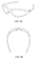
- FIGs. 3A and 3B are perspective views of an example of wraparound-type spectacle frame as viewed obliquely and from above, respectively.
- the wraparound-type spectacle frame having a large bend angle is curved along the shape of the wearer's face.
- lenses attached to the wraparound frame reach the sides of the face, and provide wide vision.
- the wraparound-type spectacle frame is used for spectacles such as protection spectacles for sports and eyeball protection spectacles to be worn by athletes.
- JP-A-2005-284059 discloses an optical design method appropriate for a spectacle frame having a large bend angle such as a wraparound-type frame.
- the optical design method disclosed in the above reference does not include a design method for a presbyopia correcting progressive-power lens.
- a spectacle lens design method for designing a spectacle lens attached to a spectacle frame having a bend angle of 200 degrees or larger includes: setting a distance portion, a near portion having power different from power of the distance portion, and a progressive portion which is disposed between the distance portion and the near portion and has a power progressively varying on at least either an object side refractive surface or an eyeball side refractive surface of the spectacle lens; adding astigmatic power to the entire distance portion for canceling aberration produced by the bend angle of the spectacle frame at a design reference point of the distance portion and astigmatic power to the entire near portion on either the object side refractive surface or the eyeball side refractive surface of the spectacle lens;for canceling aberration produced by the bend angle of the spectacle frame at a design reference point of the near portion; determining an aspherical surface addition quantity which provides the optimum optical properties throughout the object side refractive surface or the eyeball side refractive surface of the spectacle lens; and adding prismatic power to the entire distance portion for canceling prismatic power produced
- the spectacle lens design method is a method for designing a progressive-power lens provided with a progressive refractive surface which has the distance portion, the near portion having power different from power of the distance portion, and the progressive portion which is disposed between the distance portion and the near portion and has power progressively varying on the object side refractive surface or the eyeball side refractive surface of the spectacle lens.
- Astigmatic power, prismatic power and the like are produced on the spectacle lens by the presence of the bend angle of the spectacle frame, and it is necessary to correct these powers.
- the progressive refractive surface has the distance portion and the near portion, and there is a difference in dioptric power called addition power between these portions.
- correction quantity to be added to the distance portion is different from that to be added to the near portion.
- the progressive portion having the intermediate portion whose dioptric power gradually varies exists, and the inclination angles to the vision on the left side and the right side are asymmetric with respect to the vision in a spectacle lens inclined with respect to the vision in the left-right direction.
- the correction quantity on the ear side is different from the correction quantity on the nose side.
- the reference progressive refractive surface is initially established, and the design reference point is set for each of the distance portion and near portion. Then, astigmatic powers for canceling astigmatic powers produced by the bend angle at the respective design reference points of the distance portion and near portion are added to the distance portion and near portion. Subsequently, the aspherical surface addition quantity providing the optimum optical properties is calculated for the entire refractive surface on the object side or the eyeball side. Finally, prismatic powers for canceling prismatic powers produced by the bend angle of the spectacle frame at the respective design reference points of the distance portion and near portion are added to the distance portion and near portion. By correcting the effect caused by the presence of the bend angle using this method, the progressive-power lens can be attached to the spectacle frame having the large bend angle.
- the aspherical surface addition quantity determining step determines the aspherical surface addition quantity by setting a plurality of reference lines extending radially from a geometrical center of the spectacle lens through the distance portion of the spectacle lens to the edge of the spectacle lens and a plurality of reference lines extending through the near portion of the spectacle lens to the edge of the spectacle lens, calculating aspherical surface addition quantities providing the optimum optical properties on the respective reference lines, and calculating aspherical surface addition quantities for areas between the reference lines by interpolation.
- the inclination angles to the vision on the left side and the right side of the design reference point are asymmetric with respect to the vision.
- reference lines are set for the distance portion and the near portion, and aspherical surface addition quantities providing the optimal optical properties along the reference lines are calculated.
- aspherical surface addition quantities in the area between the reference lines are calculated.
- Fig. 1 illustrates a general idea about division of a reference progressive refractive surface in a spectacle lens design method according to an embodiment of the invention, showing an example of the division.
- Fig. 2A illustrates an example of establishment of reference lines
- Fig. 2B is a graph showing a method for calculating aspherical surface addition quantities between the reference lines by interpolation.
- Figs. 3A and 3B illustrate a wraparound-type spectacle frame.
- Fig. 3A is a perspective view of the spectacle frame as viewed obliquely
- Fig. 3B is a perspective view as viewed from above.
- Figs. 4A and 4B illustrate general ideas about a bend angle and an inclination angle, respectively.
- a spectacle lens design method is a method for designing a progressive-power lens capable of providing the optimum optical characteristics when the progressive-power lens is attached to a wraparound-type spectacle frame having a large bend angle shown in Figs. 3A and 3B.
- the bend angle of the spectacle frame refers to an angle formed by left and right rim surfaces as illustrated in Fig. 4A, and produces inside bend condition when the bend angle is smaller than 180 degrees, and outside bend condition when the bend angle is larger than 180 degrees.
- the spectacle lens design method designs a progressive-power lens having optical properties suitable for a spectacle frame in the outside bend condition having a bend angle of 200 degrees or larger.
- bend angles of wraparound-type spectacle frames now available on the market lie in the range from about 200 to about 250 degrees.
- a spectacle frame having a bend angle of 200 degrees or larger is used for a wraparound-type spectacle frame as shown in Figs. 3A and 3B, water goggles, protection glasses, or the like.
- the spectacle frame having an angle of 200 degrees or larger is curved along the shape of the wearer's face.
- the spectacle lens is fixed in such a condition as to be inclined with respect to the vision.
- the spectacle lens attached to the spectacle frame having a bend angle of 200 degrees or larger needs to have a larger curvature than that of an ordinary spectacle lens.
- the curvature of the object side refractive surface is generally 5 dioptres or larger when expressed in power, and typically in the range from 6 to 12 dioptres.
- the object side refractive surface and the eyeball side refractive surface of the ordinary spectacle lens are designed assuming that the lens is attached to a spectacle frame having a bend angle of 180 degrees, that is, having no bend.
- a spectacle frame for eye examination having no bend is used.
- the spectacle lens having optical properties appropriate for the spectacle frame having no bend is fixed in such a condition as to be inclined with respect to the vision, a problem arises in view of optical properties.
- the spectacle lens appropriate for the spectacle frame having the bend angle of 180 degrees is attached to a spectacle frame having a bend angle of 200 degrees or larger, at least the prismatic power and the aberration produced by the bend angle and producing astigmatic power are present on the spectacle lens.
- blurred images are viewed through the spectacle lens.
- the design method disclosed in JP-A-2005-284059 can solve this problem, but this design method is practically used for a single focus lens.
- the spectacle lens design method according to the embodiment of the invention is a method for designing a presbyopia correcting progressive-power lens which provides the optimum optical properties when attached to a spectacle frame having a large bend angle such as a wraparound-type spectacle frame.
- a reference progressive refractive surface is initially established, and a design reference point is determined for a distance portion and a near portion (progressive refractive surface setting step). Then, astigmatic powers for canceling astigmatic powers produced by a bend angle at the respective design reference points in the distance portion and the near portion are added (astigmatic power adding step). Subsequently, an aspherical surface addition quantity providing the optimum optical properties is calculated throughout the object side refractive surface or the eyeball side refractive surface (aspherical surface addition quantity determining step). Further, prismatic powers for canceling prismatic powers produced by the bend angle of the spectacle frame at the respective design reference points in the distance portion and the near portion are added (prismatic power adding step).
- a reference progressive refractive surface is established.
- the spectacle lens is divided into regions of a distance portion located in the upper area of the lens for viewing a distant place, a near portion located in the lower area of the lens for viewing a near object, and a progressive portion smoothly connecting the distance portion and the near portion for viewing an intermediate distance.
- the progressive-power lens design is roughly divided into so-called distance and near combination design providing balanced arrangement of both distant view and near view, distance and intermediate design chiefly providing wide and distant view and intermediate view, and intermediate and near design chiefly providing view in the range from the intermediate area around 1 meter of the wearer to the close area.
- the progressive-power lens design is roughly divided into aberration concentrated type having the widened distance portion and near portion and concentrated aberration in the narrow progressive portion, and aberration dispersed type having the narrowed distance portion and near portion and dispersed intermediate portion aberration in the widened progressive portion.
- the spectacle lens design method according to the embodiment of the invention is applicable to progressive-power spectacle lenses in all categories.
- the progressive refractive surface may be provided either on the object side refractive surface (outside surface) or on the eyeball side refractive surface (inside surface), or may be divided to be formed on both surfaces.
- Fig. 1 illustrates an example of divisions of the distance portion, near portion, and progressive portion on the reference progressive-power lens.
- the distance portion and near portion are sectors having a distance center and a near center, respectively.
- the distance and near portions are indicated by dotted areas in the figure.
- This spectacle lens is for the left eye, and its main meridian indicated by a relatively bold line is curved toward the nose in the -left side of the figure from the distance center to the near center considering congestion of the eye.
- the shape of the lens to be attached to the wraparound-type spectacle frame indicated by a broken line is an elongate shape in the transverse direction, which shape is long in the left-right direction and short in the vertical direction.
- the wraparound-type spectacle is for sport use, and requires wide view in the left-right direction in the distance portion.
- the distance portion occupies the upper half above the boundary of the horizontal line passing the geometrical center of the round lens.
- the main meridian extends in the central area of the distance portion in the vertical direction, and reaches the distance center (geometrical center) at the lower end of the distance portion. Then, the main meridian slightly turns toward the nose considering the congestion in the progressive portion to reach the near center, and again extends in the vertical direction to reach the lens lower end.
- the progressive band length as the length of the progressive portion is slightly short, and the progressive portion on which aberration is concentrated is relatively narrow.
- the addition power as the difference in dioptric power between the distance portion and the near portion is at most approximately 2.0.
- the addition power is larger than this value, aberration is concentrated on the progressive portion and waving and distortion are caused.
- the spectacle lens having excessively large addition power is inappropriate for sport use.
- the near portion is narrowed, only such an emergency level of addition power which can provide view sufficient for recognizing golf scores is required.
- the reference progressive-power lens can be divided by methods other than that shown in Fig. 1.
- the progressive-power lens having the bend angle of 180 degrees according to the prescription in the ordinary design is established as the reference progressive-power lens.
- the inclination angle shown in Fig. 4B is 10 degrees, for example, which is added to the reference progressive-power lens. In the following description, therefore, only effect of the bend angle is corrected assuming that no effect of the inclination angle exists.
- the design reference point is established for each of the distance portion and the near portion. Astigmatic aberration and prismatic power produced by the bend angle vary according to the dioptric power of the lens. The dioptric power of the distance portion is different from that of the near portion, and it is thus necessary to individually correct the effect of the bend angle for the distance portion and the near portion.
- the design reference point may be an arbitrary position.
- the design reference point in the distance portion is the distance eye point as a passing position of the vision on the lens when the wearer of the spectacles views a distant place with natural posture. The distance eye point coincides with the distance center in some cases. Also, the distance eye point generally agrees with the geometrical center of the lens.
- the distance center coincides with the geometrical center of the lens, and that the distance center (geometrical center) is the design reference point in the distance portion.
- the near portion it is preferable that the near center corresponds to the design reference point in the near portion.
- astigmatic power adding step astigmatic power for canceling the aberration produced by the bend angle of the spectacle frame at the design reference point of the distance portion is added to the entire distance portion on the object side or eyeball side refractive surface of the spectacle lens.
- astigmatic power for canceling the aberration produced by the bend angle of the spectacle frame at the design reference point of the near portion is added to the entire near portion.
- the astigmatic power for correction according to the bend angle and the dioptric power of the distance portion is added to the entire distance portion to cancel the astigmatic power produced by the bend angle at the design reference point of the distance portion using the correcting astigmatic power thus added such that the astigmatic power becomes zero.
- near portion correction a sector area including the entire near portion whose center is located at the geometrical center and the main meridian of the progressive portion is established, for example. Then, the correcting astigmatic power according to the bend angle and the dioptric power of the near portion is added to the established sector area to cancel the astigmatic power produced by the bend angle at the design reference point of the near portion using the correcting astigmatic power thus added such that the astigmatic power becomes zero.
- the correction is added to the near portion and the area including the main meridian of the progressive portion as one area so as to prevent discontinuity of the progressive portion.
- interpolation can be executed in such a manner as to smoothly connect the respective correction values for the distance portion and near portion.
- an aspherical surface addition quantity for providing the optimum optical properties throughout the object side refractive surface or eyeball side refractive surface is calculated. Even when the astigmatic and prismatic aberrations produced by the bend angle are corrected at the design reference point, the inclination angles with respect to the vision are asymmetric on the left side and right side of the design reference point for the entire spectacle lens inclined with respect to the vision in the left-right direction. Thus, correction is not completely performed.
- a plurality of reference lines (straight lines) extending from the geometrical center of the spectacle lens through the distance portion to the spectacle lens edge in the radial directions are initially established.
- a plurality of reference lines (straight lines) extending from the geometrical center of the spectacle lens through the near portion to the spectacle lens edge in the radial directions are established.
- the reference line extending at least in one direction is set in each of the left and right regions, that is, at least two reference lines in total are set for each of the distance portion and the near portion.
- the reference line is established in each of the left and right regions for the distance portion and near portion because the correction quantities on the nose side and on the ear side are asymmetric with the boundary of the vision when the lens is inclined with respect to the vision due to the presence of the bend angle.
- Fig. 2A shows the general idea about the establishment of the reference lines in the aspherical surface addition quantity determining step.
- the spectacle lens shown in Figs. 2A and 2B is a progressive-power lens of the distance and near combination design where the distance portion occupies the upper half of the lens as shown in Fig. 1.
- the reference for the spectacle lens design in the aspherical surface addition quantity determining step is generally the geometrical center of the spectacle lens, and uses the geometrical center as the center of the lens. It is possible, however, to select an arbitrary point in the vicinity of the geometrical center as the central point. According to the progressive-power lens based on the distance and near combination design, the geometric center of the spectacle lens practically agrees with the distance center as illustrated in Fig. 1.
- the step for setting the reference lines in the distance portion at least two reference lines linearly extending from the geometric center GC through the area of the distance portion to the spectacle lens edge in the radial directions are established.
- the inclination angle with respect to the vision on the nose side is different from that on the ear side with the boundary of the vertical line passing the geometrical center, that is, the main meridian in the distance portion, and thus the aspherical surface quantity to be added to the respective sides are asymmetric. It is therefore preferable to establish the same number of reference lines for the left side and the right side at equal angle intervals with the boundary of the main meridian.
- the accuracy for detecting the power of the distance portion rises as the number of the reference lines increases.
- Fig. 2A shows an example where eight reference lines ⁇ f1 through ⁇ f8 are established in the distance portion, four of which lines are provided on the left side and the other lines on the right side of the main meridian. These eight reference lines are established at equal angle intervals of 20 degrees in the anticlockwise direction from an X axis passing the geometrical center GC and extending in the horizontal direction. The eight reference lines are symmetrically disposed in the left-right direction with respect to the main meridian as the symmetric axis. It is not necessary to dispose the reference lines at equal angle intervals since interpolation is not affected by the non-equality of line arrangement.
- the reference lines in the near portion at least two reference lines linearly extending from the geometrical center GC through the region of the near portion to the spectacle lens edge in the radial directions are established.
- two reference lines ⁇ n1 and ⁇ n2 are straight lines connecting the central point GC and edge points dividing the circular arc of the sectorial near portion into three parts.
- the aspherical surface addition quantities are asymmetric on the left side and the right side in the near portion similarly to the distance portion, and it is thus preferable to establish the reference line in each of the left and right regions with the boundary of the main meridian.
- the reference lines extending from the geometrical center GC of the spectacle lens toward the lens edge in the region of the near portion such that the reference lines divide the circular arc of the sectorial near portion into five equal parts, seven equal parts, or nine equal parts.
- the reference lines are not required to be disposed at equal angle intervals similarly to the case of the distance portion. The accuracy for detecting the power of the near portion rises as the number of the reference lines increases.
- the aspherical surface addition quantity is determined for the power along each reference line thus established.
- the aspherical surface addition quantity can be determined by a known method which obtains the optimum aspherical surface addition quantity for the power along each reference line based on calculations of the dioptric power, astigmatism, prismatic power and the like by ray tracing under the same condition as that when the spectacle lens is attached to the eye.
- the aspherical addition quantity herein refers to an aspherical quantity to be added to the reference progressive refractive surface (minus addition in some cases) to form a new surface.
- the coordinate system of the spectacle lens is defined such that it includes the X axis extending in the left-right direction, the Y axis extending in the up-down direction (distance-near direction), and the Z axis in the depth direction when the progressive refractive surface is viewed from the front under the lens wearing condition.
- the first method for calculating the aspherical surface addition quantity directly calculates the coordinates of the aspherical surface addition quantity in the Z axis.
- a coordinate z p of the reference progressive refractive surface in the depth direction is expressed by the following function of the coordinates (x,y):
- Z p f x ⁇ y
- a synthesized coordinate in the Z axis direction after addition that is, a new coordinate of the progressive refractive surface is z t which is expressed by the following equation:
- Z t Zp + ⁇
- the vicinity of the lens central point GC contains less prism and thus less astigmatism is produced therein. Therefore, the aspherical surface addition quantity to be added thereto is small.
- light entering the lens outer peripheral area from the eye has an angle, and thus astigmatism is easily produced in that area. Therefore, the aspherical surface addition quantity to be added thereto to correct the astigmatism is generally large.
- the ideal aspherical surface addition quantity to be practically added considerably varies depending on the prescription of the user (dioptric power of lens), but this quantity changes according to a distance r from the central point GC.
- ⁇ ⁇ in the anticlockwise direction from the starting point of X axis passing the geometrical center GC
- the aspherical surface addition quantity ⁇ is expressed by the function of ( ⁇ , r). The same is true for the following calculation methods.
- the first method for calculating the aspherical surface addition quantity which directly calculates the coordinates provides the advantage that the calculation is facilitated.
- the second method for calculating aspherical surface addition quantity which calculates distributions of inclination provides the advantage that prism quantity control is facilitated.
- the Z coordinate can be calculated from the origin by integration.
- the third method for calculating aspherical surface addition quantity which calculates distributions of curvature provides the advantage that optical evaluation is facilitated. In this case, it is possible to facilitate designing of the lens, and thus to easily obtain the target prescription.
- the Z coordinate can be calculated from the origin by integration.
- the fourth method for calculating aspherical surface addition quantity which calculates distributions of curvature provides the advantage that optical evaluation is facilitated. In this case, it is possible to facilitate designing of the lens, and thus to easily obtain the target prescription.
- the Z coordinate can be calculated not by integration but by direct calculation.
- the fifth method for calculating aspherical surface addition quantity can design the lens such that curvature smoothly varies.
- this method provides a natural progressive surface shape causing no rapid change in dioptric power.
- the aspherical surface addition quantity ⁇ is determined as the function of the distance r from the central point GC and the angle ⁇ in the anticlockwise direction from the X axis along each reference line.
- the aspherical surface addition quantity for the power in the region between each reference line by interpolation to calculate the aspherical surface addition quantities for the entire surface of the spectacle lens.
- the interpolation herein refers to a calculation method for obtaining function values at two or more points of a function and calculating a function value at a point between those points. Examples of well-known typical interpolation methods include Lagrange's interpolation and spline interpolation. In this invention, these typical interpolation methods can be used.
- Fig. 2B is a graph in which ten points of values corresponding to the aspherical surface addition quantities ⁇ at the reference lines ⁇ f1 through ⁇ f8 and ⁇ n1 and ⁇ n2 shown in Fig. 2A at the positions (lens edges in case of Fig. 2B) having an equal distance from the central point GC are plotted, assuming that the vertical axis indicates the values of the aspherical surface addition quantity ⁇ calculated by the first through fifth methods, and that the transverse axis indicates the angle ⁇ in the anticlockwise direction from the starting point of the X axis.
- the interpolation is a calculation method for obtaining an equation of a smoothly curved line indicated by a broken line passing all values of the ten points of the aspherical surface addition quantities ⁇ shown in Fig. 2B.
- the optimum aspherical addition quantities can be determined for the regions of the entire spectacle lens.
- prismatic powers for canceling prismatic powers produced by the bend angle of the spectacle frame at the design reference points in the distance portion and the near portion are added to the object side or eyeball side refractive surface.
- the prismatic powers thus added give inclination to the refractive surface setting the respective design reference points as the center of the inclination such that the nose side corresponds to the base position.
- prismatic power for canceling prismatic power produced by the bend angle at a position on the main meridian, for example, according to the dioptric power is added to the entire progressive portion.
- the presbyopia correcting progressive-power lens designed according to the progressive refractive surface setting step, astigmatic power adding step, aspherical surface addition quantity determining step, and prismatic power adding step discussed above provides the optimum optical properties when attached to the spectacle frame having a large bend angle.
- the respective steps are usually performed in the order described as above, which order only requires the smallest possible volume of calculations.
- the prismatic power adding step is performed later, and correction of the prismatic power produced by the bend angle is not considered in the aspherical surface addition quantity determining step.
- the orders of the astigmatic power adding step, the aspherical surface addition quantity determining step, and the prismatic power adding step may be switched, for example.
- the aspherical surface addition quantity determining step can be performed after the prismatic power adding step and astigmatic power adding step are completed.
- the progressive-power lens considering dioptric power measurement by a lens meter is now discussed.
- addition power is progressively added to the lens from the progressive starting point.
- the dioptric power measuring point is generally set at a position offset toward the distance portion from the progressive starting point by 5 to 10 mm considering the beam width of the lens meter.
- aspherical surface design is provided up to the vicinity of the progressive starting point, astigmatism is produced at the time of dioptric power measurement by the lens meter. In this case, it is difficult to secure sufficient dioptric power for the lens.
- the distance and near combination design it is preferable to add not an aspherical surface but a spherical surface to the area from the progressive starting point practically coinciding with the geometric center GC to a position having a predetermined distance r.
- the distance r is preferably 7 mm or larger and smaller than 12 mm to be sufficient for covering the dioptric power measuring point.
- the spherical surface design area thus provided does not considerably influence the optical properties since the ideal aspherical surface addition quantity to be added is originally small in the area in the vicinity of the progressive starting point located close to the optical axis.
- the refractive surface for correcting astigmatism such as toric surface is not considered.
- the progressive refractive surface is formed on the object side refractive surface (outside surface) and that the toric surface is formed on the eyeball side refractive surface (inside surface)
- the effect of the bend angle can be separately corrected for each surface.
- the correction to be given to the latter toric surface requires only one design reference point, and the astigmatic power adding step and the prismatic power adding step are performed in the manner similar to those discussed above.
- the aspherical surface addition quantity to be added to the entire toric surface can be determined in the manner similar to that discussed above after establishing at least two reference lines extending in the direction of the astigmatic axis and the direction orthogonal to the astigmatic axis. It is also possible to add the correction for correcting the effect of the bend angle added to the toric surface formed on the eyeball side refractive surface to the progressive refractive surface formed on the object side refractive surface. In this case, both the correction for the progressive refractive surface and the correction for the toric surface are added to the progressive refractive surface formed on the object side refractive surface as the correction for correcting the effect of the bend angle. Since a toric surface having a simple shape is formed on the eyeball side refractive surface, shape formation and specular grinding of the eyeball side refractive surface can be performed by using a known hard abrasive plate. Thus, manufacturing is facilitated.
- a refractive surface combining the progressive and toric surfaces is produced on the eyeball side surface.
- the method for designing the combination refractive surface for combining the progressive refractive surface and the toric surface is disclosed in WO97/19382 , for example.
- the reference combination refractive surface can be established by this design method. Then, the design reference point is set for each of the distance portion and near portion on the eyeball side refractive surface to perform the astigmatic power adding step similar to that discussed above.
- the aspherical surface addition quantity to be added to the entire lens surface can be determined in the manner similar to that discussed above after establishing at least additional two reference lines extending in the direction of the astigmatic axis and the direction orthogonal to the astigmatic axis.
- the prismatic power addition step can be performed in the manner similar to that discussed above.
- the spectacle lens design method according to the embodiment of the invention is a general-purpose method capable of designing a presbyopia correcting progressive-power lens to be attached to a spectacle frame having a large bend angle such as a wraparound-type frame.
- the spectacle lens design method according to the embodiment of the invention is applicable to design and manufacture of a presbyopia correcting progressive-power lens which can provide the optimum optical properties when attached to a spectacle frame having a large bend angle such as a wraparound-type frame.
Applications Claiming Priority (1)
| Application Number | Priority Date | Filing Date | Title |
|---|---|---|---|
| JP2006235142A JP2008058576A (ja) | 2006-08-31 | 2006-08-31 | 眼鏡レンズの設計方法 |
Publications (1)
| Publication Number | Publication Date |
|---|---|
| EP1895351A1 true EP1895351A1 (en) | 2008-03-05 |
Family
ID=38605556
Family Applications (1)
| Application Number | Title | Priority Date | Filing Date |
|---|---|---|---|
| EP07016812A Withdrawn EP1895351A1 (en) | 2006-08-31 | 2007-08-28 | Spectacle lens design method |
Country Status (4)
| Country | Link |
|---|---|
| US (1) | US7762663B2 (ja) |
| EP (1) | EP1895351A1 (ja) |
| JP (1) | JP2008058576A (ja) |
| CN (1) | CN101135781A (ja) |
Cited By (1)
| Publication number | Priority date | Publication date | Assignee | Title |
|---|---|---|---|---|
| EP2363743A1 (de) * | 2010-02-08 | 2011-09-07 | Carl Zeiss Vision GmbH | Linsenelement mit verbesserter prismatischer Wirkung |
Families Citing this family (9)
| Publication number | Priority date | Publication date | Assignee | Title |
|---|---|---|---|---|
| US7717559B2 (en) | 2007-09-28 | 2010-05-18 | Seiko Epson Corporation | Method for designing spectacle lens, and spectacles |
| DE102008015189A1 (de) * | 2008-03-20 | 2009-10-01 | Rodenstock Gmbh | Umskalierung des Sollastigmatismus für andere Additionen |
| CN102937749B (zh) * | 2009-03-12 | 2014-10-29 | Hoya株式会社 | 眼镜镜片 |
| EP2270577A1 (en) * | 2009-06-30 | 2011-01-05 | Essilor International (Compagnie Générale D'Optique) | Method of and apparatus for generating a surface of an optical lens |
| JP5784418B2 (ja) * | 2011-08-30 | 2015-09-24 | Hoya株式会社 | 眼鏡レンズの設計方法、眼鏡レンズの製造方法、及び眼鏡レンズの設計システム |
| JP5952541B2 (ja) * | 2011-09-30 | 2016-07-13 | イーエイチエス レンズ フィリピン インク | 光学レンズ、光学レンズの設計方法、および光学レンズの製造装置 |
| JPWO2014141985A1 (ja) * | 2013-03-15 | 2017-02-16 | Hoya株式会社 | 眼鏡レンズ及びその製造方法並びにレンズ供給システム |
| US10782541B2 (en) | 2015-11-23 | 2020-09-22 | Carl Zeiss Vision International Gmbh | Method for designing a lens shape and spectacle lens |
| JP6707040B2 (ja) * | 2017-02-06 | 2020-06-10 | 伊藤光学工業株式会社 | 眼鏡用レンズの設計方法 |
Citations (5)
| Publication number | Priority date | Publication date | Assignee | Title |
|---|---|---|---|---|
| WO1997035224A1 (en) | 1996-03-21 | 1997-09-25 | Sola International Holdings Ltd. | Improved single vision lenses |
| WO1999063392A1 (en) | 1998-06-04 | 1999-12-09 | Sola International Holdings Ltd. | Shaped ophthalmic lenses |
| US6142624A (en) | 1998-07-17 | 2000-11-07 | Sola International Holdings Ltd. | Wide field spherical lenses and single design spectacle frames therefor |
| EP1582909A1 (en) | 2004-03-30 | 2005-10-05 | Seiko Epson Corporation | Spectacle lens |
| EP1688780A1 (en) | 2005-02-04 | 2006-08-09 | Seiko Epson Corporation | Method of designing a spectacle lens |
Family Cites Families (1)
| Publication number | Priority date | Publication date | Assignee | Title |
|---|---|---|---|---|
| JP3852116B2 (ja) | 1995-11-24 | 2006-11-29 | セイコーエプソン株式会社 | 累進多焦点レンズ及び眼鏡レンズ |
-
2006
- 2006-08-31 JP JP2006235142A patent/JP2008058576A/ja active Pending
-
2007
- 2007-08-07 US US11/834,867 patent/US7762663B2/en not_active Expired - Fee Related
- 2007-08-28 EP EP07016812A patent/EP1895351A1/en not_active Withdrawn
- 2007-08-29 CN CNA2007101472264A patent/CN101135781A/zh active Pending
Patent Citations (5)
| Publication number | Priority date | Publication date | Assignee | Title |
|---|---|---|---|---|
| WO1997035224A1 (en) | 1996-03-21 | 1997-09-25 | Sola International Holdings Ltd. | Improved single vision lenses |
| WO1999063392A1 (en) | 1998-06-04 | 1999-12-09 | Sola International Holdings Ltd. | Shaped ophthalmic lenses |
| US6142624A (en) | 1998-07-17 | 2000-11-07 | Sola International Holdings Ltd. | Wide field spherical lenses and single design spectacle frames therefor |
| EP1582909A1 (en) | 2004-03-30 | 2005-10-05 | Seiko Epson Corporation | Spectacle lens |
| EP1688780A1 (en) | 2005-02-04 | 2006-08-09 | Seiko Epson Corporation | Method of designing a spectacle lens |
Cited By (2)
| Publication number | Priority date | Publication date | Assignee | Title |
|---|---|---|---|---|
| EP2363743A1 (de) * | 2010-02-08 | 2011-09-07 | Carl Zeiss Vision GmbH | Linsenelement mit verbesserter prismatischer Wirkung |
| US8425034B2 (en) | 2010-02-08 | 2013-04-23 | Carl Zeiss Vision International Gmbh | Lens element with improved prismatic power |
Also Published As
| Publication number | Publication date |
|---|---|
| US7762663B2 (en) | 2010-07-27 |
| CN101135781A (zh) | 2008-03-05 |
| US20080284978A1 (en) | 2008-11-20 |
| JP2008058576A (ja) | 2008-03-13 |
Similar Documents
| Publication | Publication Date | Title |
|---|---|---|
| US7762663B2 (en) | Spectacle lens design method | |
| EP1882973B1 (en) | Design method for spectacle lens, spectacle lens, and spectacles | |
| JP5649008B2 (ja) | 遠方視力非点収差および近方視力非点収差の処方を使用して眼鏡レンズを決定する方法 | |
| US7070274B2 (en) | Spectacle lens | |
| JP4192899B2 (ja) | 眼鏡レンズの設計方法 | |
| EP2407815B1 (en) | Method of compiling shape data of a spectacle lens, spectacle lens shape data compiling device and spectacle lens | |
| EP0809127B9 (en) | Multifocal lens for eyeglasses and eyeglass lens | |
| US8079705B2 (en) | Production of an ophthalmic element adapted for foveal and peripheral vision | |
| JP5542447B2 (ja) | 単焦点眼鏡レンズを決定する方法および単焦点眼鏡レンズ | |
| KR101281459B1 (ko) | 안과용 렌즈를 결정하는 방법 | |
| JP5388579B2 (ja) | 眼鏡レンズ | |
| JP2007241276A (ja) | 累進焦点眼鏡レンズの決定方法 | |
| JP2009517709A (ja) | 眼鏡レンズ | |
| JP5000505B2 (ja) | 累進屈折力レンズ | |
| EP1154303A2 (en) | Progressive-power multifocal lens | |
| JP5017542B2 (ja) | 非球面眼鏡レンズ及び非球面眼鏡レンズの製造方法 | |
| US9170432B2 (en) | Low distortion eyewear lens with low optical power | |
| JP2008257272A (ja) | 眼鏡レンズの設計方法 | |
| EP2786200B1 (en) | Low distortion eyewear lens with low optical power | |
| US11194175B2 (en) | Method for providing a selection chart of nonprescription ophthalmic lenses | |
| CN114270247A (zh) | 用于将眼镜镜片配适到眼镜镜架的计算机实现方法 |
Legal Events
| Date | Code | Title | Description |
|---|---|---|---|
| PUAI | Public reference made under article 153(3) epc to a published international application that has entered the european phase |
Free format text: ORIGINAL CODE: 0009012 |
|
| AK | Designated contracting states |
Kind code of ref document: A1 Designated state(s): AT BE BG CH CY CZ DE DK EE ES FI FR GB GR HU IE IS IT LI LT LU LV MC MT NL PL PT RO SE SI SK TR |
|
| AX | Request for extension of the european patent |
Extension state: AL BA HR MK YU |
|
| 17P | Request for examination filed |
Effective date: 20080327 |
|
| AKX | Designation fees paid |
Designated state(s): AT BE BG CH CY CZ DE DK EE ES FI FR GB GR HU IE IS IT LI LT LU LV MC MT NL PL PT RO SE SI SK TR |
|
| RAP1 | Party data changed (applicant data changed or rights of an application transferred) |
Owner name: HOYA LENS MANUFACTURING PHILIPPINES INC. |
|
| RAP1 | Party data changed (applicant data changed or rights of an application transferred) |
Owner name: EHS LENS PHILIPPINES, INC. |
|
| RAP1 | Party data changed (applicant data changed or rights of an application transferred) |
Owner name: EHS LENS PHILIPPINES, INC. |
|
| 17Q | First examination report despatched |
Effective date: 20161004 |
|
| STAA | Information on the status of an ep patent application or granted ep patent |
Free format text: STATUS: EXAMINATION IS IN PROGRESS |
|
| STAA | Information on the status of an ep patent application or granted ep patent |
Free format text: STATUS: THE APPLICATION IS DEEMED TO BE WITHDRAWN |
|
| 18D | Application deemed to be withdrawn |
Effective date: 20201029 |