EP1894828B1 - Asymmetrischer Fahrradhinterbau - Google Patents
Asymmetrischer Fahrradhinterbau Download PDFInfo
- Publication number
- EP1894828B1 EP1894828B1 EP07114146A EP07114146A EP1894828B1 EP 1894828 B1 EP1894828 B1 EP 1894828B1 EP 07114146 A EP07114146 A EP 07114146A EP 07114146 A EP07114146 A EP 07114146A EP 1894828 B1 EP1894828 B1 EP 1894828B1
- Authority
- EP
- European Patent Office
- Prior art keywords
- seat
- seat stay
- stay
- outer diameter
- tube
- Prior art date
- Legal status (The legal status is an assumption and is not a legal conclusion. Google has not performed a legal analysis and makes no representation as to the accuracy of the status listed.)
- Active
Links
Images
Classifications
-
- B—PERFORMING OPERATIONS; TRANSPORTING
- B62—LAND VEHICLES FOR TRAVELLING OTHERWISE THAN ON RAILS
- B62K—CYCLES; CYCLE FRAMES; CYCLE STEERING DEVICES; RIDER-OPERATED TERMINAL CONTROLS SPECIALLY ADAPTED FOR CYCLES; CYCLE AXLE SUSPENSIONS; CYCLE SIDECARS, FORECARS, OR THE LIKE
- B62K19/00—Cycle frames
- B62K19/30—Frame parts shaped to receive other cycle parts or accessories
- B62K19/38—Frame parts shaped to receive other cycle parts or accessories for attaching brake members
-
- B—PERFORMING OPERATIONS; TRANSPORTING
- B62—LAND VEHICLES FOR TRAVELLING OTHERWISE THAN ON RAILS
- B62K—CYCLES; CYCLE FRAMES; CYCLE STEERING DEVICES; RIDER-OPERATED TERMINAL CONTROLS SPECIALLY ADAPTED FOR CYCLES; CYCLE AXLE SUSPENSIONS; CYCLE SIDECARS, FORECARS, OR THE LIKE
- B62K19/00—Cycle frames
- B62K19/02—Cycle frames characterised by material or cross-section of frame members
- B62K19/04—Cycle frames characterised by material or cross-section of frame members the material being wholly or mainly metallic, e.g. of high elasticity
- B62K19/06—Cycle frames characterised by material or cross-section of frame members the material being wholly or mainly metallic, e.g. of high elasticity tubular
-
- B—PERFORMING OPERATIONS; TRANSPORTING
- B62—LAND VEHICLES FOR TRAVELLING OTHERWISE THAN ON RAILS
- B62K—CYCLES; CYCLE FRAMES; CYCLE STEERING DEVICES; RIDER-OPERATED TERMINAL CONTROLS SPECIALLY ADAPTED FOR CYCLES; CYCLE AXLE SUSPENSIONS; CYCLE SIDECARS, FORECARS, OR THE LIKE
- B62K3/00—Bicycles
- B62K3/02—Frames
- B62K3/04—Frames having a substantially horizontal top bar
Definitions
- the invention relates to a rear suspension for a bicycle for use with a one-sided disc brake on the rear axle.
- disc brakes are mounted on both the front and rear axles.
- a rear disc brake is usually attached to the rear of the bicycle frame.
- a one-sided disc brake is installed, so that a brake disc is attached to one side of the rear frame of the bicycle frame,
- the forces and moments acting on the rear frame of a bicycle frame by a disc brake are particularly high because the brake disc and the caliper are relatively close to the rear axle, so that the forces and moments arising there are considerably greater than for example by the very short lever Forces and moments by a Rim brake arise, which is arranged along a rim at a greater distance to the rear axle.
- the seat stays In order to better absorb the braking forces occurring at the rear axle is in WO 00/76836 generic, a bicycle frame and rear suspension described, the seat stays have a distance of at least two inches to the impeller, said distance is measured from the inner surfaces of the seat struts to the widest point of the impeller.
- a disadvantage of such an arrangement is that it is a complex geometric design of the rear end, which requires an increased design effort.
- the parameters described with respect to the modulus of elasticity and the moment of inertia of the seatstays must be strictly adhered to, which requires an increased effort in material selection and processing.
- the object of the invention is to provide a reinforced rear suspension for receiving a one-sided disc brake on the rear axle, which has a simplified structure.
- a bicycle rear construction has at least one chain stay and two seat stays.
- a seat stay has a fastening device for receiving a brake caliper of a disc brake.
- This seatstay, to which the disc brake is attached, has at least partially a larger outer diameter than the second seatstay.
- the greater outer diameter of the seat stay increases its rigidity and strength. Since disk brakes are arranged eccentrically to the frame center plane in comparison with the known drum and rim brakes, increased unilateral stresses in the form of forces and moments, which must be introduced via the brake attachment and removed from the rear triangle, act during a braking operation. Due to the increased outside diameter, the reinforced seat stay can better absorb the one-sided forces and moments when operating the disc brake. In particular, the rear triangle is reinforced at exactly the point where the greatest forces and moments on the seat stay when braking occur. This point is located in the direction of the seat tube immediately above the mounting device of the caliper.
- the occurring forces and moments are primarily bending moments which act on the above-mentioned point and are directed essentially in the direction of the bottom bracket. This is due to the fact that the brake caliper of the disc brake is mounted on the side facing away from the bottom bracket of the seat stay and applying a bending moment on the seat stay in the direction of the bottom bracket upon actuation of the disc brake.
- a seat stay with an increased outer diameter has an increased rigidity, in particular with respect to bending moments. If a strut is loaded only on train and pressure, it makes sense to increase their wall thickness, while for better recording of bending moments, an enlarged outer diameter is the most effective measure. In particular, it is possible to ensure increased rigidity against bending moments with little or no increase in the weight of the seat stay. In particular, this can be realized in that the wall thickness of the reinforced seat stay compared to the second seat stay remains unchanged or even reduced.
- the outside diameter in a section of the seat stay facing the rear axle receiving recess is greater than in a section of the seat stay facing the seat stay.
- the outside diameter of the seat stay can decrease continuously from the rear axle seat to the seat stay.
- An increase in the outer diameter of the seat tube is independent of material and can be carried out both for frames made of metallic materials such as aluminum, titanium or steel, as well as for frames made of non-metallic materials such as plastics, fiber-reinforced plastics, ceramics, carbon fibers, etc.
- the larger outer diameter of the first seat stay relative to the second seat stay may extend over the entire length of the first seat stay. However, it is also possible that only a part of the first seat stay, for example one third or two thirds, has a larger outside diameter than the second seat stay.
- the described asymmetric design of the rear end can be realized both in conjunction with an unsprung and with a sprung rear axle.
- the rear section is correspondingly designed as a rear swinging arm and may likewise have the features according to the invention.
- the rear triangle can be designed in one arm, in particular as a one-armed rocker, by providing only one chain stay on one side of the rear wheel. This one-armed swingarm can also be sprung.
- the frame geometry used may be a diamond frame. However, other frame geometries are possible.
- the attachment of the disc brake can also be done on a chainstay instead of on the seatstay.
- the chain stay would have a larger outer diameter, so that this measure also leads to an increase in lightweight construction.
- the brake-side seat stay d. H. the first seat stay
- the first seat stay in the region in which the braking force is introduced into the seat stay by a factor of 1.2 to 1.4, in particular about 1.3 higher.
- the height here is the dimension of the seat stay in the vertical direction in the assembled state of the seat stay.
- the first seat stay their maximum height in the field of braking force, d. H. in the field of attachment of the caliper, as well as in adjacent thereto areas.
- the seat stay then tapers in the direction of the seat tube. This rejuvenation is preferably carried out continuously. As a result, the weight can be kept low with good absorption of the braking forces.
- the brake-side node between the first seat stay and the chain stay, or the area of the brake-side dropout is rigid.
- this area is at least twice as rigid as the dropout on the chain side.
- the brake-side seat stay has a greater height following the dropout than the chain stay following the dropout.
- the minimum product of moment of inertia and wheel elastic modulus in the seatstay direction is 350 Nm 2 .
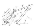
- the figure shows an oblique view of a bicycle frame with the rear triangle according to the invention.
- a bicycle frame 10 which is formed for example as a diamond frame, has a top tube 12, a down tube 14, a seat tube 16 and a control tube 18. Furthermore, the frame has a rear frame 20.
- the rear construction 20 has two chainstays 22, 24 running essentially parallel to the roadway and two seatstays 30, 32.
- the seat stays 30, 32 extend from a rear axle receptacle 28 in the direction of the point 29, at which the top tube 12 and the seat tube 16 converge.
- the Schuachsage 28 serves to accommodate the axis of a rear wheel, not shown.
- the chain stays 22, 24 extend from the rear axle receptacle 28 substantially parallel to the roadway in the direction of a bottom bracket receptacle 26, which is arranged at the meeting point of the down tube 14 and the seat tube 16.
- the left in the direction of travel 36 seat stay 30 has a fastening device 34 for receiving the caliper of a disc brake, not shown.
- a fastening device 34 for receiving the caliper of a disc brake, not shown.
- two triangular projections may be formed on the seat stay 30, to which the caliper is fastened by screws.
- An essential feature of the invention is that the seat stay 30, on which the disc brake is mounted, has a larger outer diameter than the seat stay 32, on which no disc brake is mounted.
- the seat stay 30 has a larger diameter in a section 38 pointing toward the rear axle receptacle 28 than in a section 40 facing the seat tube 16.
- the outer diameter of the seat stay 30 decreases continuously from the rear axle receptacle 28 to the seat tube 16.
- the outer diameter of the right seat stay 32 is constant from the Schuachsfact 28 in the direction of the seat tube 16.
- the fastening device 34 is arranged on the side facing away from the bottom bracket 26 side of the first seat stay 30.
- the first seat stay 30 has an enlarged outer diameter in the area which is located directly above the fastening device 34 in the direction of the seat tube 16.
- the bending moments 42 which occur most strongly at this point as a result of the braking action of the disc brake can thus be derived in an improved manner.
- only lower bending moments occur in the upper section of the first seat stay 30 facing the seat tube 16, so that it is not necessary in this area to increase the outer diameter of the first seat stay 30. Since no major bending moments due to the use of the disc brake occur on the second seat stay 32, it is likewise not necessary to provide the second seat stay 32 with a larger outside diameter. Overall, thus creating an asymmetric rear 20.
Landscapes
- Engineering & Computer Science (AREA)
- Mechanical Engineering (AREA)
- Motorcycle And Bicycle Frame (AREA)
- Body Structure For Vehicles (AREA)
- Braking Arrangements (AREA)
Description
- Die Erfindung betrifft einen Hinterbau für ein Fahrrad zur Verwendung mit einer einseitigen Scheibenbremse an der Hinterachse.
- Im Fahrradbau werden aufgrund ihrer verbesserten Bremsleistung sowohl an der Vorder- als auch an der Hinterachse Scheibenbremsen montiert. Eine Hinterradscheibenbremse ist in der Regel am Hinterbau des Fahrradrahmens befestigt. Generell wird eine einseitige Scheibenbremse verbaut, so dass eine Bremsscheibe an einer Seite des Hinterbaus des Fahrradrahmens befestigt ist,
- Die durch eine Scheibenbremse auf den Hinterbau eines Fahrradrahmens wirkenden Kräfte und Momente sind dadurch besonders hoch, dass sich die Bremsscheibe und der Bremssattel relativ nah an der Hinterachse befinden, so dass die dort entstehenden Kräfte und Momente durch den sehr kurzen Hebel erheblich größer sind als beispielsweise Kräfte und Momente, die durch eine Felgenbremse entstehen, die entlang einer Felge in einem größeren Abstand zur Hinterachse angeordnet ist.
- Um die an der Hinterachse auftretenden Bremskräfte besser aufnehmen zu können, ist in
WO 00/76836 - Aufgabe der Erfindung ist es, einen verstärkten Hinterbau zur Aufnahme einer einseitigen Scheibenbremse an der Hinterachse zu schaffen, der einen vereinfachten Aufbau aufweist.
- Die Aufgabe wird erfindungsgemäß gelöst durch die Merkmale des Anspruchs 1.
- Erfindungsgemäß weist ein Fahrradhinterbau mindestens eine Kettenstrebe sowie zwei Sitzstreben auf. Eine Sitzstrebe weist eine Befestigungsvorrichtung zur Aufnahme eines Bremssattels einer Scheibenbremse auf. Diese Sitzstrebe, an der die Scheibenbremse befestigt ist, weist zumindest teilweise einen größeren Außendurchmesser auf als die zweite Sitzstrebe.
- Durch den größeren Außendurchmesser der Sitzstrebe werden ihre Steifigkeit und Festigkeit erhöht. Da gegenüber den bekannten Trommel- und Felgenbremsen Scheibenbremsen exzentrisch zur Rahmenmittelebene angeordnet sind, wirken bei einem Bremsvorgang erhöhte einseitige Beanspruchungen in Form von Kräften und Momenten, die über die Bremsbefestigung eingeleitet und vom Hinterbau abgetragen werden müssen. Durch den erhöhten Außendurchmesser kann die verstärkte Sitzstrebe die einseitigen Kräfte und Momente beim Betätigen der Scheibenbremse besser abtragen. Insbesondere ist der Hinterbau an genau der Stelle verstärkt, an der die größten Kräfte und Momente an der Sitzstrebe beim Bremsen auftreten. Diese Stelle befindet sich in Richtung des Sattelrohrs unmittelbar über der Befestigungsvorrichtung des Bremssattels.
- Bei den auftretenden Kräften und Momenten handelt es sich in erster Linie um Biegemomente, die an der oben genannten Stelle angreifen und im Wesentlichen in Richtung des Tretlagers gerichtet sind. Dies liegt darin begründet, dass der Bremssattel der Scheibenbremse an der vom Tretlager weg weisenden Seite der Sitzstrebe angebracht ist und bei einem Betätigen der Scheibenbremse ein Biegemoment auf die Sitzstrebe in Richtung des Tretlagers aufbringt.
- Eine Sitzstrebe mit einem vergrößerten Außendurchmesser weist insbesondere gegenüber Biegemomenten eine erhöhte Steifigkeit auf. Wird eine Strebe lediglich auf Zug und Druck belastet, ist es sinnvoll, ihre Wandstärke zu vergrößern, während zum besseren Aufnehmen von Biegemomenten ein vergrößerter Außendurchmesser die effektivere Maßnahme darstellt. Insbesondere ist es möglich, bei einer geringen oder gar keinen Erhöhung des Gewichts der Sitzstrebe eine erhöhte Steifigkeit gegenüber Biegemomenten zu gewährleisten. Insbesondere kann dies dadurch realisiert werden, dass die Wandstärke der verstärkten Sitzstrebe im Vergleich zur zweiten Sitzstrebe unverändert bleibt oder sogar verringert wird.
- Da an der zweiten Seite des Hinterbaus keine Scheibenbremse angebracht ist, muss diese Seite auch nicht verstärkt ausgebildet werden. Die durch einen Bremsvorgang hervorgerufenen Kräfte und Momente treten im Wesentlichen nur auf der Seite des Hinterbaus auf, an der die Scheibenbremse montiert ist. Durch die verstärkte Ausführung von nur einer Sitzstrebe ist es gegenüber dem bisherigen Stand der Technik möglich, einen stabileren Hinterbau zur Aufnahme einer Scheibenbremse zu konstruieren und gleichzeitig Material und Gewicht einzusparen.
- Weiterhin ist es möglich, durch die asymmetrische Ausgestaltung des Hinterbaus designerische Akzente zu setzen, insbesondere da eine asymmetrische Form als Rahmengeometrie direkt ins Auge sticht.
- In einer bevorzugten Ausführungsform der Erfindung ist der Außendurchmesser in einem zur Hinterachsaufnahme weisenden Abschnitt der Sitzstrebe größer als in einem zur Sattelstrebe weisenden Abschnitt der Sitzstrebe. Der Außendurchmesser der Sitzstrebe kann dabei von der Hinterachsaufnahme zur Sattelstrebe kontinuierlich abnehmen.
- Besonders bevorzugt ist es, den Bremssattel der Scheibenbremse an der vom Tretlager weg weisenden Seite des Sitzrohres zu befestigen.
- Weiterhin ist es möglich, den Außendurchmesser des Sitzrohres lediglich im Bereich der Befestigungsvorrichtung zu vergrößern und den restlichen Außendurchmesser des Sitzrohres, beispielsweise in dem in Richtung der Sattelstütze weisenden Abschnitt, unverändert zu lassen.
- Eine Vergrößerung des Außendurchmessers des Sitzrohres ist werkstoffunabhängig und kann sowohl für Rahmen aus metallischen Werkstoffen, wie beispielsweise Aluminium, Titan oder Stahl, wie auch für Rahmen aus nichtmetallischen Werkstoffen, wie beispielsweise Kunststoffen, Faserkunststoffverbunden, Keramiken, Kohlefasern usw., durchgeführt werden.
- Der größere Außendurchmesser der ersten Sitzstrebe gegenüber der zweiten Sitzstrebe kann sich über die gesamte Länge der ersten Sitzstrebe erstrecken. Jedoch ist es auch möglich, dass lediglich ein Teil der ersten Sitzstrebe, beispielsweise ein Drittel oder zwei Drittel, einen größeren Außendurchmesser gegenüber der zweiten Sitzstrebe aufweist.
- Die beschriebene asymmetrische Ausgestaltung des Hinterbaus kann sowohl in Verbindung mit einer ungefederten als auch mit einer gefederten Hinterachse realisiert werden. Bei einer gefederten Hinterachse ist der Hinterbau entsprechend als Hinterbauschwinge ausgebildet und kann ebenfalls die erfindungsgemäßen Merkmale aufweisen. Weiterhin kann der Hinterbau einarmig, insbesondere als einarmige Schwinge ausgebildet sein, indem lediglich eine Kettenstrebe auf einer Seite des Hinterrades vorgesehen ist. Diese einarmige Schwinge kann ebenfalls gefedert sein.
- Bei der verwendeten Rahmengeometrie kann es sich um einen Diamantrahmen handeln. Jedoch sind auch weitere Rahmengeometrien möglich.
- Weiterhin kann die Befestigung der Scheibenbremse ebenso, anstatt an der Sitzstrebe, an einer Kettenstrebe erfolgen. Anstatt der Sitzstrebe müsste dann die Kettenstrebe einen größeren Außendurchmesser aufweisen, so dass diese Maßnahme ebenfalls zu einer Erhöhung der Leichtbaugüte führt.
- Erfindungsgemäß ist es somit besonders bevorzugt, dass die bremsseitige Sitzstrebe, d. h. die erste Sitzstrebe, höher ist als die zweite bzw. kettenblattseitige Sitzstrebe. Vorzugsweise ist die erste Sitzstrebe in dem Bereich in dem die Bremskraft in die Sitzstrebe eingeleitet wird um einen Faktor von 1,2 bis 1,4, insbesondere ca. 1,3 höher. Die Höhe ist hierbei die Abmessung der Sitzstrebe in vertikaler Richtung in montiertem Zustand der Sitzstrebe.
- Besonders bevorzugt ist es, dass die erste Sitzstrebe ihre maximale Höhe im Bereich der Bremskrafteinleitung, d. h. im Bereich der Befestigung des Bremssattels, sowie in hieran angrenzenden Bereichen aufweist. Vorzugsweise verjüngt sich die Sitzstrebe sodann in Richtung des Sitzrohres. Diese Verjüngung erfolgt vorzugsweise kontinuierlich. Hierdurch kann bei guter Aufnahme der Bremskräfte das Gewicht gering gehalten werden.
- Ferner ist es bevorzugt, dass der bremsseitige Knotenpunkt zwischen der ersten Sitzstrebe und der Kettenstrebe, bzw. der Bereich des bremsseitigen Ausfallendes biegesteif ausgeführt ist. Insbesondere ist dieser Bereich mindestens doppelt so biegesteif, wie das Ausfallende auf der Kettenseite. Vorzugsweise weist die bremsseitige Sitzstrebe im Anschluss an das Ausfallende eine größere Höhe auf als die Kettenstrebe im Anschluss an da Ausfallende.
- Bei dem erfindungsgemäßen Fahrradhinterbau beträgt, bezogen auf die erste Sitzstrebe, das minimale Produkt aus Trägheitsmoment und Scheibenelastizitätsmodul in Sitzstrebenrichtung 350 Nm2.
- Im Folgenden wird eine bevorzugte Ausführungsform der Erfindung anhand der Figur erläutert.
- Die Figur zeigt eine Schrägansicht eines Fahrradrahmens mit dem erfindungsgemäßen Hinterbau.
- Ein Fahrradrahmen 10, der beispielsweise als Diamantrahmen ausgebildet ist, weist ein Oberrohr 12, ein Unterrohr 14, ein Sitzrohr 16 sowie ein Steuerrohr 18 auf. Ferner weist der Rahmen einen Hinterbau 20 auf. Der Hinterbau 20 weist zwei im Wesentlichen parallel zur Fahrbahn verlaufende Kettenstreben 22,24 sowie zwei Sitzstreben 30,32 auf. Die Sitzstreben 30,32 erstrecken sich dabei von einer Hinterachsaufnahme 28 in Richtung des Punktes 29, an dem das Oberrohr 12 und das Sitzrohr 16 zusammenlaufen. Die Hinterachsaufnahme 28 dient zur Aufnahme der Achse eines nicht dargestellten Hinterrades.
- Die Kettenstreben 22,24 verlaufen von der Hinterachsaufnahme 28 im Wesentlichen parallel zur Fahrbahn in Richtung einer Tretlageraufnahme 26, die am Treffpunkt des Unterrohrs 14 und des Sitzrohrs 16 angeordnet ist.
- Die in Fahrtrichtung 36 linke Sitzstrebe 30 weist zur Aufnahme des Bremssattels einer nicht dargestellten Scheibenbremse eine Befestigungsvorrichtung 34 auf. Dafür können beispielsweise an der Sitzstrebe 30 zwei dreieckförmige Ansätze ausgebildet sein, an die der Bremssattel durch Schrauben befestigt wird.
- Wesentliches Merkmal der Erfindung ist, dass die Sitzstrebe 30, an der die Scheibenbremse montiert ist, einen größeren Außendurchmesser aufweist als die Sitzstrebe 32, an der keine Scheibenbremse montiert ist.
- Weiterhin weist die Sitzstrebe 30 in einem zur Hinterachsaufnahme 28 weisenden Abschnitt 38 einen größeren Durchmesser auf als in einem zum Sitzrohr 16 weisenden Abschnitt 40. Dabei nimmt der Außendurchmesser der Sitzstrebe 30 von der Hinterachsaufnahme 28 zum Sitzrohr 16 kontinuierlich ab. Der Außendurchmesser der rechten Sitzstrebe 32 ist von der Hinterachsaufnahme 28 in Richtung des Sitzrohrs 16 konstant.
- Die Befestigungsvorrichtung 34 ist an der vom Tretlager 26 weg weisenden Seite der ersten Sitzstrebe 30 angeordnet.
- Die erste Sitzstrebe 30 weist in dem Bereich einen vergrößerten Außendurchmesser auf, der sich direkt über der Befestigungsvorrichtung 34 in Richtung des Sitzrohrs 16 befindet. Die durch die Bremswirkung der Scheibenbremse an dieser Stelle am stärksten auftretenden Biegemomente 42 können damit verbessert abgeleitet werden. In dem oberen zum Sitzrohr 16 weisenden Abschnitt 40 der ersten Sitzstrebe 30 treten dagegen lediglich geringere Biegemomente auf, so dass es in diesem Bereich nicht notwendig ist, den Außendurchmesser der ersten Sitzstrebe 30 zu vergrößern. Da an der zweiten Sitzstrebe 32 ebenfalls keine größeren Biegemomente durch den Einsatz der Scheibenbremse entstehen, ist es ebenfalls nicht notwendig, die zweite Sitzstrebe 32 mit einem größeren Außendurchmesser zu versehen. Insgesamt entsteht somit ein asymmetrischer Hinterbau 20.
Claims (9)
- Fahrradhinterbau (20) mit
mindestens einer Kettenstrebe (22,24), und zwei Sitzstreben (30,32),
wobei eine erste Sitzstrebe (30) eine Befestigungsvorrichtung (34) zur Aufnahme eines Bremssattels einer Scheibenbremse aufweist,
dadurch gekennzeichnet, dass
die erste Sitzstrebe (30) zum besseren Aufnehmen der einseitigen Bremsmomente und -kräfte zumindest teilweise einen größeren Außendurchmesser aufweist als die zweite Sitzstrebe (32). - Fahrradhinterbau (20) nach Anspruch 1, dadurch gekennzeichnet, dass der Außendurchmesser in einem zu einer Hinterachsaufnahme (28) weisenden Abschnitt (38) der ersten Sitzstrebe (30) größer ist als in einem zum Sitzrohr (16) weisenden Abschnitt (40) der Sitzstrebe (30).
- Fahrradhinterbau (20) nach Anspruch 2, dadurch gekennzeichnet, dass der Außendurchmesser der ersten Sitzstrebe (30) von der Hinterachsaufnahme (28) zum Sitzrohr (16) kontinuierlich abnimmt.
- Fahrradhinterbau (20) nach Anspruch 2, dadurch gekennzeichnet, dass der Außendurchmesser der ersten Sitzstrebe (30) von der Hinterachsaufnahme (28) zum Sitzrohr (16) stufenweise abnimmt.
- Fahrradhinterbau (20) nach einem der Ansprüche 1 bis 4, dadurch gekennzeichnet, dass die Befestigungsvorrichtung (34) an der vom Tretlager (26) weg weisenden Seite der ersten Sitzstrebe (30) angeordnet ist.
- Fahrradhinterbau (20) nach einem der Ansprüche 1 bis 5, dadurch gekennzeichnet, dass der Außendurchmesser der ersten Sitzstrebe (30) im Bereich der Befestigungsvorrichtung (34) vergrößert ist.
- Fahrradhinterbau (20) nach einem der Ansprüche 1 bis 6, dadurch gekennzeichnet, dass die erste Sitzstrebe (30) insbesondere die erste und zweite Sitzstrebe (30,32) ausschließlich Carbon aufweisen.
- Fahrradrahmen (10) mit
einem Oberrohr (12), einem Unterrohr (14), einem Sattelrohr (16), einem Steuerrohr (18) und einem Fahrradhinterbau (20) nach einem der Ansprüche 1 bis 7. - Fahrradrahmen (10) nach Anspruch 8, dadurch gekennzeichnet, dass der Fahrradrahmen (10) als Diamantrahmen ausgebildet ist.
Applications Claiming Priority (1)
| Application Number | Priority Date | Filing Date | Title |
|---|---|---|---|
| DE202006013287U DE202006013287U1 (de) | 2006-08-30 | 2006-08-30 | Asymmetrischer Fahrradhinterbau |
Publications (3)
| Publication Number | Publication Date |
|---|---|
| EP1894828A2 EP1894828A2 (de) | 2008-03-05 |
| EP1894828A3 EP1894828A3 (de) | 2009-04-29 |
| EP1894828B1 true EP1894828B1 (de) | 2010-01-06 |
Family
ID=38830330
Family Applications (1)
| Application Number | Title | Priority Date | Filing Date |
|---|---|---|---|
| EP07114146A Active EP1894828B1 (de) | 2006-08-30 | 2007-08-10 | Asymmetrischer Fahrradhinterbau |
Country Status (4)
| Country | Link |
|---|---|
| EP (1) | EP1894828B1 (de) |
| AT (1) | ATE454312T1 (de) |
| DE (2) | DE202006013287U1 (de) |
| ES (1) | ES2336500T3 (de) |
Families Citing this family (1)
| Publication number | Priority date | Publication date | Assignee | Title |
|---|---|---|---|---|
| EP4061694B1 (de) * | 2019-11-18 | 2025-04-16 | Lauf Cycles hf. | Hinterradfederungssystem für ein fahrrad |
Family Cites Families (2)
| Publication number | Priority date | Publication date | Assignee | Title |
|---|---|---|---|---|
| DE29815887U1 (de) * | 1998-09-03 | 2000-01-05 | Storck, Markus, 65520 Bad Camberg | Fahrrad |
| EP1104382A1 (de) * | 1999-06-11 | 2001-06-06 | Cannondale Corporation | Fahrradrahmen |
-
2006
- 2006-08-30 DE DE202006013287U patent/DE202006013287U1/de not_active Expired - Lifetime
-
2007
- 2007-08-10 ES ES07114146T patent/ES2336500T3/es active Active
- 2007-08-10 DE DE502007002536T patent/DE502007002536D1/de active Active
- 2007-08-10 AT AT07114146T patent/ATE454312T1/de active
- 2007-08-10 EP EP07114146A patent/EP1894828B1/de active Active
Also Published As
| Publication number | Publication date |
|---|---|
| EP1894828A3 (de) | 2009-04-29 |
| ES2336500T3 (es) | 2010-04-13 |
| DE202006013287U1 (de) | 2008-01-03 |
| EP1894828A2 (de) | 2008-03-05 |
| ATE454312T1 (de) | 2010-01-15 |
| DE502007002536D1 (de) | 2010-02-25 |
Similar Documents
| Publication | Publication Date | Title |
|---|---|---|
| DE10041046B4 (de) | Aufhängungssystem für Fahrzeuge | |
| DE102010064685B4 (de) | Fahrradrahmen mit gelenkiger Gestänge-Befestigungsanordnung | |
| EP0861744B1 (de) | Verbundlenker-Hinterachse für Kraftfahrzeuge | |
| DE60309188T2 (de) | Fahrradsatteltrügeranordnung | |
| EP2540533B1 (de) | Radaufhängung für ein Fahrzeug | |
| DE112005002152T5 (de) | Fahrzeugaufhängungsarmstützstruktur | |
| DE102008007722A1 (de) | Speiche aus Verbundmaterial für ein Speichenrad | |
| DE102017120874A1 (de) | Schwenklager | |
| WO2004083669A1 (de) | Scheibenbremse mit auf bolzen geführten bremsbelägen | |
| DE102011016628A1 (de) | Schwenklager | |
| DE202014011186U1 (de) | Scheibenbremse und Bremsbelagsatz einer Scheibenbremse | |
| DE102007015510A1 (de) | Fahrzeugscheibenbremse mit integrierter Trommelbremse und Verfahren zu ihrer Herstellung | |
| DE102012021289A1 (de) | Fahrzeugachse für ein Kraftfahrzeug sowie Kraftfahrzeug mit einer derartigen Fahrzeugachse | |
| EP0899133B1 (de) | Einzelradaufhängung einer Hinterachse | |
| EP1894828A2 (de) | Asymmetrischer Fahrradhinterbau | |
| DE19520520A1 (de) | Biegesteifer Lenker aus Rohrmaterial | |
| DE102012006093B4 (de) | Scheibenbremse für ein Nutzfahrzeug | |
| EP1574366B1 (de) | Achsaufhängung und Federplatte für eine Achsanbindung | |
| EP1399358B1 (de) | Fahrradrahmen | |
| DE202009000904U1 (de) | Fahrrad-Steckachsensystem | |
| EP0899186B1 (de) | Federnde, lenkbare Achsaufhängung für ein Zweirad | |
| WO2018046462A1 (de) | Bremssattel einer scheibenbremse | |
| EP3838707B1 (de) | Hängelasche für ein bremsgestänge eines schienenfahrzeuges, bremsgestänge und verfahren zur schwingungsdämpfung eines bremsgestänges eines schienenfahrzeuges | |
| WO2020221569A1 (de) | Einzelradaufhängung für ein zweispuriges fahrzeug, achse und fahrzeug | |
| DE102007026087B4 (de) | Radaufhängung |
Legal Events
| Date | Code | Title | Description |
|---|---|---|---|
| PUAI | Public reference made under article 153(3) epc to a published international application that has entered the european phase |
Free format text: ORIGINAL CODE: 0009012 |
|
| AK | Designated contracting states |
Kind code of ref document: A2 Designated state(s): AT BE BG CH CY CZ DE DK EE ES FI FR GB GR HU IE IS IT LI LT LU LV MC MT NL PL PT RO SE SI SK TR |
|
| AX | Request for extension of the european patent |
Extension state: AL BA HR MK YU |
|
| PUAL | Search report despatched |
Free format text: ORIGINAL CODE: 0009013 |
|
| AK | Designated contracting states |
Kind code of ref document: A3 Designated state(s): AT BE BG CH CY CZ DE DK EE ES FI FR GB GR HU IE IS IT LI LT LU LV MC MT NL PL PT RO SE SI SK TR |
|
| AX | Request for extension of the european patent |
Extension state: AL BA HR MK RS |
|
| RAP1 | Party data changed (applicant data changed or rights of an application transferred) |
Owner name: CANYON BICYCLES GMBH |
|
| 17P | Request for examination filed |
Effective date: 20090514 |
|
| GRAP | Despatch of communication of intention to grant a patent |
Free format text: ORIGINAL CODE: EPIDOSNIGR1 |
|
| GRAS | Grant fee paid |
Free format text: ORIGINAL CODE: EPIDOSNIGR3 |
|
| GRAA | (expected) grant |
Free format text: ORIGINAL CODE: 0009210 |
|
| AK | Designated contracting states |
Kind code of ref document: B1 Designated state(s): AT BE BG CH CY CZ DE DK EE ES FI FR GB GR HU IE IS IT LI LT LU LV MC MT NL PL PT RO SE SI SK TR |
|
| REG | Reference to a national code |
Ref country code: GB Ref legal event code: FG4D Free format text: NOT ENGLISH |
|
| REG | Reference to a national code |
Ref country code: CH Ref legal event code: EP |
|
| REG | Reference to a national code |
Ref country code: CH Ref legal event code: NV Representative=s name: ISLER & PEDRAZZINI AG |
|
| REG | Reference to a national code |
Ref country code: IE Ref legal event code: FG4D |
|
| REF | Corresponds to: |
Ref document number: 502007002536 Country of ref document: DE Date of ref document: 20100225 Kind code of ref document: P |
|
| REG | Reference to a national code |
Ref country code: ES Ref legal event code: FG2A Ref document number: 2336500 Country of ref document: ES Kind code of ref document: T3 |
|
| REG | Reference to a national code |
Ref country code: NL Ref legal event code: T3 |
|
| PG25 | Lapsed in a contracting state [announced via postgrant information from national office to epo] |
Ref country code: SI Free format text: LAPSE BECAUSE OF FAILURE TO SUBMIT A TRANSLATION OF THE DESCRIPTION OR TO PAY THE FEE WITHIN THE PRESCRIBED TIME-LIMIT Effective date: 20100106 |
|
| LTIE | Lt: invalidation of european patent or patent extension |
Effective date: 20100106 |
|
| PG25 | Lapsed in a contracting state [announced via postgrant information from national office to epo] |
Ref country code: PT Free format text: LAPSE BECAUSE OF FAILURE TO SUBMIT A TRANSLATION OF THE DESCRIPTION OR TO PAY THE FEE WITHIN THE PRESCRIBED TIME-LIMIT Effective date: 20100506 Ref country code: IS Free format text: LAPSE BECAUSE OF FAILURE TO SUBMIT A TRANSLATION OF THE DESCRIPTION OR TO PAY THE FEE WITHIN THE PRESCRIBED TIME-LIMIT Effective date: 20100506 Ref country code: LT Free format text: LAPSE BECAUSE OF FAILURE TO SUBMIT A TRANSLATION OF THE DESCRIPTION OR TO PAY THE FEE WITHIN THE PRESCRIBED TIME-LIMIT Effective date: 20100106 |
|
| REG | Reference to a national code |
Ref country code: IE Ref legal event code: FD4D |
|
| PG25 | Lapsed in a contracting state [announced via postgrant information from national office to epo] |
Ref country code: PL Free format text: LAPSE BECAUSE OF FAILURE TO SUBMIT A TRANSLATION OF THE DESCRIPTION OR TO PAY THE FEE WITHIN THE PRESCRIBED TIME-LIMIT Effective date: 20100106 Ref country code: FI Free format text: LAPSE BECAUSE OF FAILURE TO SUBMIT A TRANSLATION OF THE DESCRIPTION OR TO PAY THE FEE WITHIN THE PRESCRIBED TIME-LIMIT Effective date: 20100106 Ref country code: LV Free format text: LAPSE BECAUSE OF FAILURE TO SUBMIT A TRANSLATION OF THE DESCRIPTION OR TO PAY THE FEE WITHIN THE PRESCRIBED TIME-LIMIT Effective date: 20100106 |
|
| PG25 | Lapsed in a contracting state [announced via postgrant information from national office to epo] |
Ref country code: RO Free format text: LAPSE BECAUSE OF FAILURE TO SUBMIT A TRANSLATION OF THE DESCRIPTION OR TO PAY THE FEE WITHIN THE PRESCRIBED TIME-LIMIT Effective date: 20100106 Ref country code: IE Free format text: LAPSE BECAUSE OF FAILURE TO SUBMIT A TRANSLATION OF THE DESCRIPTION OR TO PAY THE FEE WITHIN THE PRESCRIBED TIME-LIMIT Effective date: 20100106 Ref country code: GR Free format text: LAPSE BECAUSE OF FAILURE TO SUBMIT A TRANSLATION OF THE DESCRIPTION OR TO PAY THE FEE WITHIN THE PRESCRIBED TIME-LIMIT Effective date: 20100407 Ref country code: EE Free format text: LAPSE BECAUSE OF FAILURE TO SUBMIT A TRANSLATION OF THE DESCRIPTION OR TO PAY THE FEE WITHIN THE PRESCRIBED TIME-LIMIT Effective date: 20100106 Ref country code: SE Free format text: LAPSE BECAUSE OF FAILURE TO SUBMIT A TRANSLATION OF THE DESCRIPTION OR TO PAY THE FEE WITHIN THE PRESCRIBED TIME-LIMIT Effective date: 20100106 Ref country code: CY Free format text: LAPSE BECAUSE OF FAILURE TO SUBMIT A TRANSLATION OF THE DESCRIPTION OR TO PAY THE FEE WITHIN THE PRESCRIBED TIME-LIMIT Effective date: 20100106 |
|
| PLBE | No opposition filed within time limit |
Free format text: ORIGINAL CODE: 0009261 |
|
| STAA | Information on the status of an ep patent application or granted ep patent |
Free format text: STATUS: NO OPPOSITION FILED WITHIN TIME LIMIT |
|
| PG25 | Lapsed in a contracting state [announced via postgrant information from national office to epo] |
Ref country code: SK Free format text: LAPSE BECAUSE OF FAILURE TO SUBMIT A TRANSLATION OF THE DESCRIPTION OR TO PAY THE FEE WITHIN THE PRESCRIBED TIME-LIMIT Effective date: 20100106 Ref country code: CZ Free format text: LAPSE BECAUSE OF FAILURE TO SUBMIT A TRANSLATION OF THE DESCRIPTION OR TO PAY THE FEE WITHIN THE PRESCRIBED TIME-LIMIT Effective date: 20100106 Ref country code: BG Free format text: LAPSE BECAUSE OF FAILURE TO SUBMIT A TRANSLATION OF THE DESCRIPTION OR TO PAY THE FEE WITHIN THE PRESCRIBED TIME-LIMIT Effective date: 20100406 |
|
| 26N | No opposition filed |
Effective date: 20101007 |
|
| PG25 | Lapsed in a contracting state [announced via postgrant information from national office to epo] |
Ref country code: DK Free format text: LAPSE BECAUSE OF FAILURE TO SUBMIT A TRANSLATION OF THE DESCRIPTION OR TO PAY THE FEE WITHIN THE PRESCRIBED TIME-LIMIT Effective date: 20100106 |
|
| PG25 | Lapsed in a contracting state [announced via postgrant information from national office to epo] |
Ref country code: MC Free format text: LAPSE BECAUSE OF NON-PAYMENT OF DUE FEES Effective date: 20100831 |
|
| PG25 | Lapsed in a contracting state [announced via postgrant information from national office to epo] |
Ref country code: MT Free format text: LAPSE BECAUSE OF FAILURE TO SUBMIT A TRANSLATION OF THE DESCRIPTION OR TO PAY THE FEE WITHIN THE PRESCRIBED TIME-LIMIT Effective date: 20100106 |
|
| PG25 | Lapsed in a contracting state [announced via postgrant information from national office to epo] |
Ref country code: HU Free format text: LAPSE BECAUSE OF FAILURE TO SUBMIT A TRANSLATION OF THE DESCRIPTION OR TO PAY THE FEE WITHIN THE PRESCRIBED TIME-LIMIT Effective date: 20100707 Ref country code: LU Free format text: LAPSE BECAUSE OF NON-PAYMENT OF DUE FEES Effective date: 20100810 |
|
| PG25 | Lapsed in a contracting state [announced via postgrant information from national office to epo] |
Ref country code: TR Free format text: LAPSE BECAUSE OF FAILURE TO SUBMIT A TRANSLATION OF THE DESCRIPTION OR TO PAY THE FEE WITHIN THE PRESCRIBED TIME-LIMIT Effective date: 20100106 |
|
| PGFP | Annual fee paid to national office [announced via postgrant information from national office to epo] |
Ref country code: AT Payment date: 20130821 Year of fee payment: 7 |
|
| REG | Reference to a national code |
Ref country code: AT Ref legal event code: MM01 Ref document number: 454312 Country of ref document: AT Kind code of ref document: T Effective date: 20140810 |
|
| PG25 | Lapsed in a contracting state [announced via postgrant information from national office to epo] |
Ref country code: AT Free format text: LAPSE BECAUSE OF NON-PAYMENT OF DUE FEES Effective date: 20140810 |
|
| REG | Reference to a national code |
Ref country code: FR Ref legal event code: PLFP Year of fee payment: 10 |
|
| REG | Reference to a national code |
Ref country code: FR Ref legal event code: PLFP Year of fee payment: 11 |
|
| PGFP | Annual fee paid to national office [announced via postgrant information from national office to epo] |
Ref country code: NL Payment date: 20170823 Year of fee payment: 11 |
|
| PGFP | Annual fee paid to national office [announced via postgrant information from national office to epo] |
Ref country code: BE Payment date: 20170823 Year of fee payment: 11 |
|
| REG | Reference to a national code |
Ref country code: FR Ref legal event code: PLFP Year of fee payment: 12 |
|
| REG | Reference to a national code |
Ref country code: NL Ref legal event code: MM Effective date: 20180901 |
|
| REG | Reference to a national code |
Ref country code: BE Ref legal event code: MM Effective date: 20180831 |
|
| PG25 | Lapsed in a contracting state [announced via postgrant information from national office to epo] |
Ref country code: NL Free format text: LAPSE BECAUSE OF NON-PAYMENT OF DUE FEES Effective date: 20180901 |
|
| PG25 | Lapsed in a contracting state [announced via postgrant information from national office to epo] |
Ref country code: IT Free format text: LAPSE BECAUSE OF NON-PAYMENT OF DUE FEES Effective date: 20180810 |
|
| PG25 | Lapsed in a contracting state [announced via postgrant information from national office to epo] |
Ref country code: BE Free format text: LAPSE BECAUSE OF NON-PAYMENT OF DUE FEES Effective date: 20180831 |
|
| PGFP | Annual fee paid to national office [announced via postgrant information from national office to epo] |
Ref country code: CH Payment date: 20220824 Year of fee payment: 16 |
|
| P01 | Opt-out of the competence of the unified patent court (upc) registered |
Effective date: 20230420 |
|
| PGFP | Annual fee paid to national office [announced via postgrant information from national office to epo] |
Ref country code: GB Payment date: 20230824 Year of fee payment: 17 Ref country code: ES Payment date: 20230918 Year of fee payment: 17 |
|
| PGFP | Annual fee paid to national office [announced via postgrant information from national office to epo] |
Ref country code: FR Payment date: 20230821 Year of fee payment: 17 |
|
| REG | Reference to a national code |
Ref country code: CH Ref legal event code: PL |
|
| PG25 | Lapsed in a contracting state [announced via postgrant information from national office to epo] |
Ref country code: CH Free format text: LAPSE BECAUSE OF NON-PAYMENT OF DUE FEES Effective date: 20230831 |
|
| GBPC | Gb: european patent ceased through non-payment of renewal fee |
Effective date: 20240810 |
|
| PG25 | Lapsed in a contracting state [announced via postgrant information from national office to epo] |
Ref country code: GB Free format text: LAPSE BECAUSE OF NON-PAYMENT OF DUE FEES Effective date: 20240810 |
|
| PG25 | Lapsed in a contracting state [announced via postgrant information from national office to epo] |
Ref country code: FR Free format text: LAPSE BECAUSE OF NON-PAYMENT OF DUE FEES Effective date: 20240831 |
|
| REG | Reference to a national code |
Ref country code: ES Ref legal event code: FD2A Effective date: 20250926 |
|
| PG25 | Lapsed in a contracting state [announced via postgrant information from national office to epo] |
Ref country code: ES Free format text: LAPSE BECAUSE OF NON-PAYMENT OF DUE FEES Effective date: 20240811 |
|
| PGFP | Annual fee paid to national office [announced via postgrant information from national office to epo] |
Ref country code: DE Payment date: 20250815 Year of fee payment: 19 |