EP4061694B1 - Hinterradfederungssystem für ein fahrrad - Google Patents
Hinterradfederungssystem für ein fahrrad Download PDFInfo
- Publication number
- EP4061694B1 EP4061694B1 EP20767548.9A EP20767548A EP4061694B1 EP 4061694 B1 EP4061694 B1 EP 4061694B1 EP 20767548 A EP20767548 A EP 20767548A EP 4061694 B1 EP4061694 B1 EP 4061694B1
- Authority
- EP
- European Patent Office
- Prior art keywords
- leaf spring
- rear wheel
- seat tube
- suspension system
- wheel suspension
- Prior art date
- Legal status (The legal status is an assumption and is not a legal conclusion. Google has not performed a legal analysis and makes no representation as to the accuracy of the status listed.)
- Active
Links
Images


Classifications
-
- B—PERFORMING OPERATIONS; TRANSPORTING
- B62—LAND VEHICLES FOR TRAVELLING OTHERWISE THAN ON RAILS
- B62K—CYCLES; CYCLE FRAMES; CYCLE STEERING DEVICES; RIDER-OPERATED TERMINAL CONTROLS SPECIALLY ADAPTED FOR CYCLES; CYCLE AXLE SUSPENSIONS; CYCLE SIDE-CARS, FORECARS, OR THE LIKE
- B62K25/00—Axle suspensions
- B62K25/04—Axle suspensions for mounting axles resiliently on cycle frame or fork
- B62K2025/041—Axle suspensions for mounting axles resiliently on cycle frame or fork the cycle frame being made of a flexible material
-
- B—PERFORMING OPERATIONS; TRANSPORTING
- B62—LAND VEHICLES FOR TRAVELLING OTHERWISE THAN ON RAILS
- B62K—CYCLES; CYCLE FRAMES; CYCLE STEERING DEVICES; RIDER-OPERATED TERMINAL CONTROLS SPECIALLY ADAPTED FOR CYCLES; CYCLE AXLE SUSPENSIONS; CYCLE SIDE-CARS, FORECARS, OR THE LIKE
- B62K2201/00—Springs used in cycle frames or parts thereof
- B62K2201/06—Leaf springs
Definitions
- the present invention relates to a rear wheel suspension system for a bike, and to a bike (bicycles and motorbikes) comprising such a suspension system.
- the invention preferably seeks to mitigate, alleviate or eliminate one or more of the above-mentioned disadvantages of the prior art, singly or in any combination.
- a rear wheel suspension system (101) for a bike comprising:
- said left side flexible chainstay and said right side flexible chainstay, said left side seatstay and said right side seatstay, said leaf spring and said seat tube of said rear wheel suspension system are all a part of the same non-disassemblable body, this can for example, but not limited to, be achieved by monocoque composite material manufacturing techniques, by bonding of composite material parts or by welding of metal parts.
- said left side flexible chainstay and said right side flexible chainstay, said left side seatstay and said right side seatstay, said leaf spring and said seat tube of said rear wheel suspension system are made of more than one disassemblable bodies, this can for example, but not limited to, be achieved by bolting together, snapping into place, etc.
- said leaf spring has a solid cross section.
- said leaf spring has a hollow cross section.
- said seatstays are at least 30% thinner on average in the majority of their upmost lengthwise third than the lower at least 2/3 rd lengthwise remainder of said seatstays are on average.
- said leaf spring and said left and right seat stays are interconnected via a pivot.
- said leaf spring and said seatstays do not have a clearly defined transition point, instead a transition area is defined where one gradually morphs into the other, with the upmost part of said seatstays providing substantial leaf spring functionality.
- said seat tube and said leaf spring are formed so that the effective spring length of said leaf spring is shortened as the said rear wheel suspension system compresses, by said leaf spring coming into contact with said seat tube at designated one or more locations, direct contact or indirect contact through intermediate bodies such as elastomer materials.
- more than 30% of the length of said top and bottom surfaces of said leaf spring is at any given location less than 12° from being parallel to said seat tube of said bike.
- more than 50% of the length of said top and bottom surfaces of said leaf spring is at any given location less than 12° from being parallel to said seat tube of said bike.
- the width of said leaf spring at any given height above ground location is, when looked at from the front, within 10mm of the width of said seat tube in the same height above ground location.
- said rear wheel suspension system further comprises one or more stiffness adjustment elements, such as stiffness adjustment inserts, preferably arranged and secured in place between said leaf spring and said seat tube. Said one or more stiffness adjustment inserts may be secured in place by any applicable fastening methods.
- the stiffness adjustment inserts may in particular be configured and arranged to adjust the effective spring length of the leaf spring, notably to reduce the effective spring length.
- riders of different body weight and/or with different riding preferences may shorten the effective spring length of said leaf spring and thus increase the spring rate of said rear wheel suspension system.
- one or more of said one or more stiffness adjustment inserts are each contacting both said leaf spring and said seat tube when rider is stationary in riding position on said bike.
- one or more of said one or more stiffness adjustment inserts are each contacting only either said leaf spring or said seat tube when rider is stationary in riding position on said bike, then each contacting both said leaf spring and said seat tube when further compressed into its suspension travel.
- said one or more stiffness adjustment inserts can make for a progressive spring rate suspension system, as the said one or more inserts can come into contact with both sides when the suspension system has partially compressed and thereby decreasing the effective spring length, this is a benefit for riders who want extra sensitive suspension for smaller hits, while having stiffer suspension deeper into the suspension travel.
- one or more of said one or more stiffness adjustment inserts are elevatable in a direction substantially perpendicularly to said top and bottom surfaces of said leaf spring; either secured to said leaf spring and adjustable in how far they are elevated towards said seat tube, or secured to said seat tube and adjustable in how far they are elevated towards said leaf spring, said one or more stiffness adjustment inserts being secured in place by any applicable fastening method.
- the said elevatable stiffness adjustment insert when fully reaching the opposite side, with a rider stationary in riding position on said bike, shortening the effective spring length of said leaf spring and thus stiffening the suspension, making it suit riders preferring stiffer suspension, when partially reaching the opposite side the said elevatable stiffness adjustment insert can make for a progressive spring rate suspension system, as the said elevatable stiffness adjustment insert comes into contact with the opposite side when the suspension system has partially compressed, this is a benefit for riders who want extra sensitive suspension for smaller hits, while having stiffer suspension deeper into the suspension travel.
- one or more of said one or more elevatable stiffness adjustment inserts can be elevated by actuators such as, but not limited to, hydraulic pistons, screw jacks, etc.
- Said actuators can, e.g. but not limited to, be manually operated via buttons, levers, turn knobs, dials or with a tool such as an Allen key or screwdriver. Operation of said actuators can be via a cable- or hydraulically connected remote, furthermore, said actuators can e.g. be driven by electric motors, either controlled via an electrical wire connected remote or via a wireless remote.
- Said cable-, hydraulic-, electrical wire- or electrical wireless- remotes can for instance be mounted on the handlebar of said bike.
- said top and bottom surfaces of said leaf spring are substantially parallel to the adjacent surface of said seat tube on the lengthwise portion of said leaf spring that reaches from where said leaf spring and seat tube connect, at the root of said leaf spring, to a portion at least 30% downwards along the length of said leaf spring.
- the feature "substantially parallel” in particular means that the top and bottom surfaces of the leaf spring define an angle relative to the adjacent surface of the seat tube of at most 6 degrees, such as an angle of at most 4 degrees, such as an angle of at most 2 degrees. Angles in these ranges allow the stiffness adjustment insert to fulfil its purpose by being able to reach between the surfaces of the leaf spring and the seat tube over the lengthwise portion of said leaf spring that reaches from where said leaf spring and seat tube connect at the root of said leaf spring, to the position at least 30% upwards along the length of the leaf spring.
- the top and bottom surfaces of the leaf spring need not be completely parallel with the adjacent surface of the seat tube; for example, the leaf spring may be shaped and configured such that it pre-loads (or compresses) the slidable insert slightly.
- the gap between the spring and the seat tube may thus be slightly narrower away from the spring root than at the spring root.
- the insert slides away from the spring root, it provides an outwardly directed biasing force to the spring to displace it by a few millimeters or less, e.g., at most 5 mm, such as preferably at most 2 mm.
- said top and bottom surfaces of said leaf spring are substantially parallel to the adjacent surface of said seat tube on the lengthwise portion of said leaf spring that reaches from where said leaf spring and seat tube connect, at the root of said leaf spring, to a portion at least 30% downwards along the length of said leaf spring, in this said substantially parallel lengthwise portion of said top and bottom surfaces of said leaf spring the substantially perpendicular distance E between said leaf spring and said seat tube being between 1mm and 40mm, such as 5-20mm.
- said top and bottom surfaces of said leaf spring are substantially parallel to the adjacent surface of said seat tube on the lengthwise portion of said leaf spring that reaches from where said leaf spring and seat tube connect, at the root of said leaf spring, and from there to a portion at least 30% downwards along the length of said leaf spring.
- said leaf spring is substantially straight in said portion at least 30% downwards along the length of said leaf spring.
- said perpendicular distance E is achieved through a kink in the shape of said leaf spring at its root, above said portion of said leaf spring where it is substantially parallel to the adjacent surface of said seat tube.
- said perpendicular distance E is achieved through said leaf spring connecting to the posterior part of a posteriorly elevated portion of said seat tube, elevated perpendicularly from said seat tube as it is in the said substantially parallel lengthwise portion of said top and bottom surfaces of said leaf spring.
- said body achieving said perpendicular distance E is defined as a part of the root of said leaf spring.
- one or more of said one or more stiffness adjustment inserts are slidable upwards and downwards along and between said leaf spring and said seat tube. Said one or more slidable stiffness adjustment inserts are preferably guided to prevent lateral movement. When the rider is stationary in riding position on said bike said one or more slidable stiffness adjustment inserts can either reach entirely between said leaf spring and said seat tube, or reach partially between said leaf spring and said seat tube.
- the said one or more slidable stiffness adjustment inserts may confer a progressive spring rate suspension system, as the said insert achieves contacts with both said leaf spring and said seat tube when the suspension system has partially compressed, this is a benefit for riders who want extra sensitive suspension for smaller hits, while having stiffer suspension deeper into the suspension travel. Being slidable upwards/downwards can enable a rider to conveniently adjust his suspension according to his preference.
- said one or more slidable stiffness adjustment inserts are between 5-40mm long, i.e. in the upwards/downwards direction.
- one or more of said one or more slidable stiffness adjustment inserts comprise a mechanically gripping texture A that interacts with a matching opposing mechanically gripping texture B on said leaf spring and or on said seat tube, said one or more mechanically gripping slidable stiffness adjustment inserts further comprising means of pressuring said opposing mechanically gripping textures A and B together, said pressuring may be done via, but not limited to, spring loading, screw tightening, etc.
- said pressuring of said opposing mechanically gripping textures A and B together is achieved through a spring-loaded lever, where pushing or pulling the lever levitates said pressure and thus allows said slidable stiffness adjustment insert to be slid upwards or downwards while lever is pushed or pulled.
- said rear wheel suspension system further comprises a linear actuator for sliding one or more of said one or more slidable stiffness adjustment inserts upwardly and downwardly.
- Said linear actuator can e.g. be a screw jack, scissor drive, rack and pinion drive, hydraulic actuator, pneumatic actuator, pullable wire plus retracting spring combo, etc.
- said linear actuator extends downwards from said one or more of said one or more slidable stiffness adjustment inserts and then connects its other end, directly or via an intermediate body, to the remainder of said bike, e.g. said leaf spring or said seat tube.
- said linear actuator is arranged in a groove that runs up and down the posterior surface of said seat tube (with the notable exclusion of a scissor drive linear actuator, as it would not easily fit in a groove).
- said linear actuator is arranged in a groove that runs up and down the posterior surface of said seat tube (with the notable exclusion of a scissor drive linear actuator, as it would not easily fit in a groove) said one or more of said one or more slidable stiffness adjustment inserts have an extrusion shaped to interact laterally with the surface of said groove.
- said linear actuator extends downwards from said one or more of said one or more slidable stiffness adjustment inserts and then extending further through an opening on the posterior surface of said seat tube, into a cavity in said seat tube.
- said linear actuators can, e.g. but not limited to, be manually operated via buttons, levers, turn knobs, dials or with a tool such as an allen key or screwdriver. Operation of said actuators can be via a cable- or hydraulically connected remote. Furthermore, said actuators can e.g. be driven by electric motors, either controlled via an electrical wire connected remote or via a wireless remote. Said cable-, hydraulic-, electrical wire- or electrical wireless- remotes can for instance be mounted on the handlebar of said bike.
- said wheel or pinion is connected to a drive mechanism operated via, but not limited to, a button, a lever, a turn knob, a dial or via a tool such as an allen key or screwdriver, operation can e.g. be via a cable- or hydraulically connected remote, or in the case when said drive mechanism is powered by one or more electric motors, either via electrical-wire connected remote or via wireless remote, said remotes, weather they are connected by a cable-, hydraulic line, electrical wire- or electrical wireless communications, can for instance be mounted on the handlebar of said bike.
- one or more of said one or more stiffness adjustment inserts are formed so that the thickness of said one or more of said one or more stiffness adjustment inserts at the end that is closer to the root of said leaf spring is such that, when rider is stationary in riding position on said bike, it reaches entirely between said leaf spring and said seat tube, while its thickness at the end further away from the root of said leaf spring is such that it lacks up to 5mm to reach entirely between said leaf spring and seat tube.
- the seatstays are connected to the seat tube solely via the leaf spring and the optional stinffnes adjustment insert, with no other elements interconnecting the seat stays and the seat tube.
- Such embodiments save weight, do not add other connections that could slow down the suspension response and/or add maintenance and are simple and inexpensive, given that a minimum of parts are needed.
- said rear wheel suspension system further comprises a liner material fully or partially covering surfaces of said leaf spring and or said seat tube that otherwise could come into contact with each other and or into contact with one or more of said one or more stiffness adjustment inserts
- said liner material can be made of, but is not limited to, titanium, steel, a plastic or elastomer material, said liner material is defined to become a part of the body it is attached to, whether it being said leaf spring or said seat tube.
- an elastomer bump stop is located and secured in place between said leaf spring and said seat tube.
- said rear wheel suspension system further comprises a forwardly extending damper arranged from said seatstays to said seat tube.
- said left side flexible chainstay and said right side flexible chainstay connect to said seat tube between 100mm and 250mm above the rotational axis of the bottom bracket area of said bike, both said left side flexible chainstay and said right side flexible chainstay connecting to said seat tube at substantially the same height.
- said one or more stiffness adjustment inserts have their widths extending at least essentially between the left and right edge of said leaf spring.
- an adjustable rear wheel suspension system that does not roll excessively to the sides when the rider is pedaling or maneuvering.
- the present invention relates to a bike comprising said rear wheel suspension system.
- a bike can mean; a conventional pedal powered bicycle, motor assisted pedal powered bicycle or a motor bike.
- said seatstays, said chainstays, said dropout, said seat tube, said leaf spring and said one or more stiffness adjustment inserts can be made out of, but not limited to being made out of, e.g. composite materials such as epoxy reinforced carbon fiber or glass fiber, aluminum, steel, titanium, plastic materials, elastomers, wood, etc.
- FIG 1 shows a rear wheel suspension system (101) for a bike, the bike comprising:
- said left side flexible chainstay and said right side flexible chainstay, said left side seatstay and said right side seatstay, said leaf spring and said seat tube of said rear wheel suspension system are all a part of the same non-disassemblable body, this can for example, but not limited to, be achieved by monocoque composite material manufacturing techniques, by bonding of composite material parts or by welding of metal parts.
- said left side flexible chainstay and said right side flexible chainstay, said left side seatstay and said right side seatstay, said leaf spring and said seat tube of said rear wheel suspension system are made of more than one disassemblable bodies, this can for example, but not limited to, be achieved by bolting together, snapping into place, etc.
- said leaf spring has a solid cross section.
- said leaf spring has a hollow cross section.
- FIGs 2a and 2b show deformation under load of an embodiment of said rear wheel suspension system, where said seatstays are at least 30% thinner on average in the majority of their upmost length-wise third 201, when said bike is looked at directly from the left or right, than the lower at least 2/3 rd length-wise remainder of said seatstays are on average.
- FIG 2b shows deformation under load where said seatstays have a uniform higher thickness and thus force said leaf spring to flex into an S-shape rather than flexing as a simple cantilever beam.
- FIG 2a enabling easy deformation of the said majority of upmost length-wise third of said seatstays, thus enabling the lower end of said leaf spring to tilt substantially under load compared to the root of said leaf spring by said seat tube, i.e. enabling said leaf spring to flex more as a cantilever beam from its root at connection to said seat tube, as opposed to taking on a S-shape under load, between said seat tube and said seatstays.
- this enables designs of said leaf spring that are better at carrying a high load at a given amount of maximum wheel travel, as the said leaf spring can be made thicker in this configuration and thus stronger, while still providing the required flex.
- Comparison seatstays that are thin for their entire length would however result in a relatively flimsy ride feel, as they would not pinpoint the flex of said seatstays to the desired location in the top 3 rd but rather distribute it over its entire length.
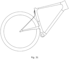
- FIG 3 shows an embodiment of said rear wheel suspension system, where said leaf spring and said seatstays do not have a clearly defined transition point, instead a transition area 301 is defined where one gradually morphs into the other, with the upmost part of said seatstays providing substantial leaf spring functionality.
- FIG 4 shows an embodiment of said rear wheel suspension system, where said seat tube and said leaf spring are formed so that the effective spring length of said leaf spring is shortened as the said rear wheel suspension system compresses, by said leaf spring coming into contact with said seat tube at designated one or more locations 401, direct contact or indirect contact through intermediate bodies such as elastomer materials.
- FIG 5 shows an embodiment of said rear wheel suspension system, where more than 30% of the length of said top and bottom surfaces of said leaf spring leaf spring is at any given location less than 12° from being parallel to said seat tube of said bike, an angle for point P on said leaf spring shown as A° in figure.
- more than 50% of the length of said top and bottom surfaces of said leaf spring is at any given location less than 12° from being parallel to said seat tube of said bike.
- FIG 6 shows an embodiment of said rear wheel suspension system, where the width of said leaf spring WLS at any given height above ground location is, when looked at from behind, within 10mm of the width of said seat tube WST in the same height above ground location, for clarity said rotably attached rear wheel and said seatstays are not shown on this figure, dotted lines showing the + 10mm and -10mm widths from said seat tube.
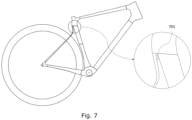
- said rear wheel suspension system further comprises one or more stiffness adjustment inserts, arranged and secured in place between said leaf spring and said seat tube, said one or more stiffness adjustment inserts being secured in place by any applicable fastening methods.
- FIG 7 shows an embodiment of said rear wheel suspension system, where one or more of said one or more stiffness adjustment inserts 701 are each contacting both said leaf spring and said seat tube when rider is stationary in riding position on said bike.
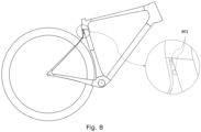
- FIG 8 shows an embodiment of said rear wheel suspension system, where one or more of said one or more stiffness adjustment inserts 801 are each contacting only either said leaf spring or said seat tube when rider is stationary in riding position on said bike, then each contacting both said leaf spring and said seat tube when further compressed into its suspension travel.
- said one or more stiffness adjustment inserts can make for a progressive spring rate suspension system, as the said one or more inserts can come into contact with both sides when the suspension system has partially compressed and thereby decreasing the effective spring length, this is a benefit for riders who want extra sensitive suspension for smaller hits, while having stiffer suspension deeper into the suspension travel.
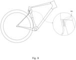
- FIG 9 shows, according to the invention, where one or more of said one or more stiffness adjustment inserts 901 are elevatable substantially perpendicularly to said top and bottom surfaces of said leaf spring; secured to said seat tube and adjustable in how far they are elevated towards said leaf spring, said one or more stiffness adjustment inserts being secured in place by any applicable fastening method.
- the said elevatable stiffness adjustment insert when fully reaching the opposite side, with a rider stationary in riding position on said bike, shortening the effective spring length of said leaf spring and thus stiffening the suspension, making it suit riders preferring stiffer suspension, when partially reaching the opposite side the said elevatable stiffness adjustment insert can make for a progressive spring rate suspension system, as the said elevatable stiffness adjustment insert comes into contact with the opposite side when the suspension system has partially compressed, this is a benefit for riders who want extra sensitive suspension for smaller hits, while having stiffer suspension deeper into the suspension travel.
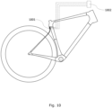
- FIG 10 shows an embodiment of said rear wheel suspension system comprising said one or more elevatable stiffness adjustment inserts, where one or more of said one or more elevatable stiffness adjustment inserts 1001 can be elevated by actuators such as, but not limited to, hydraulic pistons, screw jacks, etc.
- actuators such as, but not limited to, hydraulic pistons, screw jacks, etc.
- Said actuators can, e.g. but not limited to, be manually operated via buttons, levers, turn knobs, dials or with a tool such as an allen key or screwdriver. Operation of said actuators can be via a cable- or hydraulically connected remote, furthermore, said actuators can e.g. be driven by electric motors, either controlled via an electrical wire connected remote or via a wireless remote 1002.
- Said cable-, hydraulic-, electrical wire- or electrical wireless- remotes can for instance be mounted on the handlebar of said bike.
- said top and bottom surfaces of said leaf spring are substantially parallel to the adjacent surface of said seat tube on the lengthwise portion of said leaf spring that reaches from where said leaf spring and seat tube connect, at the root of said leaf spring, to a portion at least 30% downwards along the length of said leaf spring.
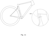
- FIG 11 shows an embodiment of said rear wheel suspension system
- said top and bottom surfaces of said leaf spring are substantially parallel to the adjacent surface of said seat tube on the lengthwise portion of said leaf spring that reaches from where said leaf spring and seat tube connect, at the root of said leaf spring, to a portion at least 30% downwards along the length of said leaf spring, in this said substantially parallel lengthwise portion 1101 of said top and bottom surfaces of said leaf spring the substantially perpendicular distance E between said leaf spring and said seat tube being between 1mm and 40mm, such as 5-20mm.
- FIG 12 shows an embodiment of said rear wheel suspension system, where said perpendicular distance E is achieved through a kink 1201 in the shape of said leaf spring at its root, above said portion of said leaf spring where it is substantially parallel to the adjacent surface of said seat tube.
- FIG 13 shows an embodiment of said rear wheel suspension system, where said perpendicular distance E is achieved through said leaf spring connecting to the posterior part of a posteriorly elevated portion 1301 of the seat tube, elevated perpendicularly from said seat tube as it is in the said substantially parallel lengthwise portion of said leaf spring.
- Dotted lines in the figure show examples of how said seat tube can further be elevated posteriorly in areas outside of the substantially parallel lengthwise portion of said leaf spring.
- said perpendicular distance E is e.g. achieved through said kink in the shape of said leaf spring, via a said posteriorly elevated portion of the seat tube, a combination of the two, or any other comparable methods, said body achieving said perpendicular distance E is defined as a part of said root of said leaf spring.
- FIG 14 shows, according to the invention, where one or more of said one or more stiffness adjustment inserts are slidable upwards and downwards along and between said leaf spring and said seat tube, said one or more slidable stiffness adjustment inserts 1401 being guided to prevent lateral movement, when rider is stationary in riding position on said bike said one or more slidable stiffness adjustment inserts can either reach entirely between said leaf spring and said seat tube, or reach partially between said leaf spring and said seat tube.
- the said one or more slidable stiffness adjustment inserts can make for a progressive spring rate suspension system, as the said insert achieves contacts with both said leaf spring and said seat post when the suspension system has partially compressed, this is a benefit for riders who want extra sensitive suspension for smaller hits, while having stiffer suspension deeper into the suspension travel. Being slidable upwards/downwards can enable a rider to conveniently adjust his suspension according to his preference.
- said one or more slidable stiffness adjustment inserts are between 5-40mm long, i.e. in the upwards/downwards direction.
- FIG 15 shows an embodiment of said rear wheel suspension system, comprising one or more slidable stiffness adjustment inserts, where one or more of said one or more slidable stiffness adjustment inserts 1501 comprise a mechanically gripping texture A that interacts with a matching opposing mechanically gripping texture B on said leaf spring (this interaction could just as well take place on said seat tube), said one or more mechanically gripping slidable stiffness adjustment inserts further comprising means of pressuring said opposing mechanically gripping textures A and B together, said pressuring may be done via, but not limited to, spring loading, screw tightening, etc.
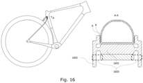
- FIG 16 shows an embodiment of said rear wheel suspension system, where said mechanically gripping textures A and B are located laterally on said seat tube (could equally be located laterally on said leaf spring for same effect) where said pressuring of said opposing mechanically gripping textures A and B together is achieved through a spring-loaded lever 1602, where pushing said lever levitates said pressure and thus allows said slidable stiffness adjustment insert 1601 to be slid upwards or downwards while lever is pushed or pulled.
- Similar designs could reach same effect when said lever is puller rather than pushed, in the pictured embodiment this would be achieved by moving mechanically gripping textures to locations within dotted boxes 1603, making said mechanically gripping textures A and B located on same "side" as said lever.
- said rear wheel suspension system comprising one or more slidable stiffness adjustment inserts
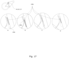
- said rear wheel suspension system further comprising a linear actuator for sliding one or more of said one or more slidable stiffness adjustment inserts upwardly and downwardly.
- Said linear actuator can e.g. be a screw jack, scissor drive, rack and pinion drive, hydraulic actuator, pneumatic actuator, pullable wire plus retracting spring combo, etc.
- B screw jack with driving mechanism 1703
- C pneumatic or hydraulic actuator
- D pullable wire plus retracting spring combo
- said linear actuator is arranged in a groove that runs up and down the posterior surface of said seat tube (with the notable exclusion of a scissor drive linear actuator, as it would not easily fit in a groove).
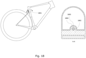
- FIG 18 shows an embodiment of said rear wheel suspension system comprising said linear actuator 1801, with slidable stiffness adjustment insert 1802, where said linear actuator is arranged in a groove 1803 that runs up and down the posterior surface of said seat tube (with the notable exclusion of a scissor drive linear actuator, as it would not easily fit in a groove) said one or more of said one or more slidable stiffness adjustment inserts have an extrusion 1804 shaped to interact laterally with the surface of said groove.
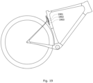
- FIG 19 shows an embodiment of said rear wheel suspension system comprising said linear actuator 1901, where said linear actuator extends downwards from said one or more of said one or more slidable stiffness adjustment inserts and then extending further through an opening 1902 on the posterior surface of said seat tube, into a cavity 1903 in said seat tube.
- FIG 20 shows an embodiment of said rear wheel suspension system, comprising said root of said leaf spring 2001, where said root of said leaf spring has a hole 2002 up into it, that gives linear actuators that reach upwards from said one or more of said one or more slidable stiffness adjustment inserts access to added space above where said leaf spring at location P reaches said root of said leaf spring.
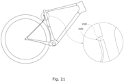
- FIG 21 shows an embodiment of said rear wheel suspension system, comprising said root of said leaf spring 2101, where said root of said leaf spring has a hole 2102 up through it, that gives linear actuators that reach upwards from said one or more of said one or more slidable stiffness adjustment inserts access to added space above where said leaf spring at location P reaches said root of said leaf spring.
- FIG 22 shows an embodiment of said rear wheel suspension system, comprising said root of said leaf spring 2201, where said root of said leaf spring has a hole 2202 up through it, wherein said linear actuator 2203 is arranged in a groove that runs up and down the posterior surface of said seat tube, with said one or more of said one or more slidable stiffness adjustment inserts having an extrusion shaped to interact laterally with the surface of said groove, said linear actuator is in this embodiment a screw jack with the input torque applied from above through said hole through said root of said leaf spring, the linear actuator action taking place through threads in said slidable stiffness adjustment insert.
- FIG 23 shows an embodiment of said rear wheel suspension system, where said linear actuators 2301 can, e.g. but not limited to, be manually operated via buttons, levers, turn knobs, dials or with a tool such as an allen key or screwdriver. Operation of said actuators can be via a cable- or hydraulically connected remote 2302. Furthermore, said actuators can e.g. be driven by electric motors, either controlled via an electrical wire connected remote or via a wireless remote. Said cable-, hydraulic-, electrical wire- or electrical wireless- remotes can for instance be mounted on the handlebar of said bike.
- FIG 24 shows an embodiment of said rear wheel suspension system, comprising said one or more slidable stiffness adjustment inserts 2401, where said linear actuator is a rack and pinion system that comprises a wheel or pinion 2402 mounted on one or more of said one or more slidable stiffness adjustment inserts that interacts with cogged or toothed racks/bars or rails 2403 that are fixed to said leaf spring and/or seat tube and extending upwards/downwards along said leaf spring and/or seat tube.
- said linear actuator is a rack and pinion system that comprises a wheel or pinion 2402 mounted on one or more of said one or more slidable stiffness adjustment inserts that interacts with cogged or toothed racks/bars or rails 2403 that are fixed to said leaf spring and/or seat tube and extending upwards/downwards along said leaf spring and/or seat tube.
- FIG 25 shows an embodiment of said rear wheel suspension system, comprising said one or more slidable stiffness adjustment inserts 2501, said linear actuator is a rack and pinion system that comprises a wheel or pinion 2503 mounted to either said seat tube or said leaf spring, then interacting with cogged or toothed racks/bars or rails 2502 that are fixed to one or more of said one or more slidable inserts extending upwards/downwards along said leaf spring and/or seat tube.
- said linear actuator is a rack and pinion system that comprises a wheel or pinion 2503 mounted to either said seat tube or said leaf spring, then interacting with cogged or toothed racks/bars or rails 2502 that are fixed to one or more of said one or more slidable inserts extending upwards/downwards along said leaf spring and/or seat tube.
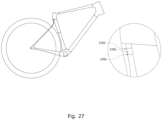
- FIG 27 shows an embodiment of said rear wheel suspension system, comprising one or more stiffness adjustment inserts 2701, where one or more of said one or more stiffness adjustment inserts are formed so that the thickness of said one or more of said one or more stiffness adjustment inserts at the end 2702 that is closer to the root of said leaf spring is such that, when rider is stationary in riding position on said bike, it reaches entirely between said leaf spring and said seat tube, while its thickness at the end 2703 further away from the root of said leaf spring is such that it lacks up to 5mm to reach entirely between said leaf spring and seat tube.
- each of said one or more of said one or more stiffness adjustment inserts provide more than one spring rate for said rear wheel suspension system, i.e. providing progressive stiffness. Stiffness ramping up as the end further away from the intersection of said leaf spring and seat tube comes in contact with both said leaf spring and seat tube, as the said suspension system has been partially compressed.
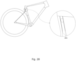
- FIG 28 shows an embodiment of said rear wheel suspension system comprising said one or more stiffness adjustment inserts, where said rear wheel suspension system further comprises a liner material 2801 fully or partially covering surfaces of said leaf spring and or said seat tube that otherwise could come into contact with each other and or into contact with one or more of said one or more stiffness adjustment inserts, said liner material can be made of, but is not limited to, titanium, steel, a plastic or elastomer material, said liner material is defined to become a part of the body it is attached to, whether it being said leaf spring or said seat tube.
- FIG 29 shows an embodiment of said rear wheel suspension system, where an elastomer bump stop 2901 is located and secured in place between said leaf spring and said seat tube.
- FIG 30 shows an embodiment of said rear wheel suspension system, where said rear wheel suspension system further comprises a forwardly extending damper 3001 arranged from said seatstays or lower half of said leaf spring to said seat tube.
- Said damper can just as well be mounted to other locations on bike frame's front triangle, such as its top tube.
- FIG 31 shows an embodiment of said rear wheel suspension system, where said left side flexible chainstay and said right side flexible chainstay connect to said seat tube between 100mm and 250mm above the rotational axis of the bottom bracket area of said bike, both said left side flexible chainstay and said right side flexible chainstay connecting to said seat tube at substantially the same height.
- said one or more stiffness adjustment inserts have their widths extending at least essentially between the left and right edge of said leaf spring.
- an adjustable rear wheel suspension system that does not roll excessively to the sides when the rider is pedaling or maneuvering.
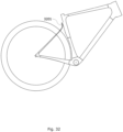
- FIG 32 shows an example of an embodiment of said rear wheel suspension system, where said leaf spring 3201 is relatively short, but still falling under the scope of the present invention.
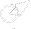
- FIG 33 shows an example of an embodiment of said rear wheel suspension system, where said leaf spring 3301 is relatively long, but still falling under the scope of the present invention.
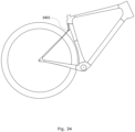
- FIG 34 shows an embodiment of said rear wheel suspension system, where said leaf spring and said left and right seat stays are interconnected via a pivot 3401.
Landscapes
- Engineering & Computer Science (AREA)
- Mechanical Engineering (AREA)
- Axle Suspensions And Sidecars For Cycles (AREA)
- Springs (AREA)
Claims (13)
- Hinterradaufhängungssystem (101) für ein Zweirad, das Zweirad umfassend:• ein Hinterrad (109) mit einem Höchstradius (R), wobei das Hinterrad eine Mittelebene (CP) definiert, die senkrecht zu der Drehachse des Hinterrads ist und koinzident mit dem Bodenkontakt des Hinterrads ist, wenn sich das Zweirad aufrecht auf ebenem Boden befindet,das Hinterradaufhängungssystem (101) umfassend:• ein Sattelrohr (104),• ein Tretlagergehäuse (106), das eine Drehachse (105) definiert, die sich in einer Richtung quer zu der Mittelebene (CP) durch das Tretlagergehäuse erstreckt, das einen Teil des Sattelrohrs (104) bildet oder sicher daran befestigt ist,• eine linksseitige flexible Kettenstrebe (102) und eine rechtsseitige flexible Kettenstrebe (103), die sich längsverlaufend auf jeder Seite der Mittelebene (CP) erstrecken, wobei jede mit ihrem vorderen Ende dazu konfiguriert ist, weniger als 250 mm von der Drehachse (105) eines Tretlagergehäuses (106) an einem unteren Abschnitt des Sattelrohrs (104) des Zweirads befestigt zu sein,• eine linksseitige Sattelstrebe (107) und eine rechtsseitige Sattelstrebe (108), wobei jede untere Endbereiche aufweist, die mit hinteren Endbereichen von jeder der flexiblen Kettenstreben verbunden sind, und wobei sich jede der Sattelstreben nach oben und nach vorne erstreckt, wobei deren gegenüberliegendes Ende dazu konfiguriert ist, sich zu einer Position zu erstrecken, die außerhalb des Höchstradius (R) des drehbar befestigten Hinterrads (109) und in einem Abstand von einem oberen Abschnitt des Sattelrohrs des Zweirads liegt,• einen Satz Ausfallenden (110), die sich dort befinden, wo die flexiblen Kettenstreben und die Sattelstreben miteinander verbunden sind, um das Hinterrad des Zweirads drehbar zu stützen,• eine Blattfeder (111), welche die Sattelstreben und das Sattelrohr miteinander verbindet, wobei ein Ende der Blattfeder (111) mit dem oberen Endbereich der Sattelstreben verbunden ist und wobei sich die Blattfeder (111) von ihrem Verbindungspunkt mit dem oberen Endbereich der Sattelstreben nach oben zu einem Verbindungspunkt mit dem Sattelrohr des Zweirads erstreckt, wobei die Blattfeder gegenüberliegende oberste und unterste Oberflächen definiert, die sich quer zu der Mittelebene (CP) erstrecken,• ein oder mehrere Steifigkeitsanpassungseinsätze (701, 801, 901, 1001, 1401, 1501, 1601, 1802, 2401, 2501, 2701), die zwischen der Blattfeder und dem Sattelrohr angeordnet sind und an Ort und Stelle gehalten werden,• wobei die Blattfeder in einer Richtung senkrecht zu der obersten und untersten Oberfläche der Blattfeder in einem Abstand D zu dem Sattelrohr angeordnet ist, um ein Biegen der Blattfeder zu dem Sattelrohr und damit ein vertikales Biegen der flexiblen Kettenstreben zu ermöglichen,• dadurch gekennzeichnet, dass• einer oder mehrere der Steifigkeitsanpassungseinsätze im Wesentlichen senkrecht zu der obersten und untersten Oberfläche der Blattfeder erhöhbar sind oder entlang und zwischen der Blattfeder und dem Sattelrohr nach oben und unten verschiebbar sind.
- Hinterradaufhängungssystem nach Anspruch 1, wobei die linksseitige flexible Kettenstrebe und die rechtsseitige flexible Kettenstrebe, die linksseitige Sattelstrebe und die rechtsseitige Sattelstrebe, die Blattfeder und das Sattelrohr des Hinterradaufhängungssystems alle Teil des gleichen, nicht auseinandernehmbaren Körpers sind.
- Hinterradaufhängungssystem nach Anspruch 1 oder 2, wobei die Sattelstreben in der Mehrheit ihres längsgerichteten oberen Drittels durchschnittlich mindestens 30 % dünner sind als die längsgerichteten verbleibenden 2/3 der Sattelstreben durchschnittlich sind.
- Hinterradaufhängungssystem nach einem der vorhergehenden Ansprüche, wobei das Sattelrohr und die Blattfeder so gebildet sind, dass die effektive Federlänge der Blattfeder verkürzt wird, wenn das Hinterradaufhängungssystem komprimiert wird, indem die Blattfeder an einer oder mehreren festgelegten Stellen mit dem Sattelrohr in Kontakt kommt.
- Hinterradaufhängungssystem nach einem der vorhergehenden Ansprüche, wobei mehr als 30 % der Länge der obersten und untersten Oberfläche der Blattfeder an jeder beliebigen Stelle weniger als 12° davon entfernt sind, parallel zu dem Sattelrohr des Zweirads zu sein.
- Hinterradaufhängungssystem nach einem der vorhergehenden Ansprüche, wobei die oberste und unterste Oberfläche der Blattfeder an dem längsgerichteten Abschnitt der Blattfeder, der von dort, wo die Blattfeder und das Sattelrohr verbunden sind, an der Wurzel der Blattfeder, bis zu einem Abschnitt von mindestens 30 % nach unten entlang der Länge der Blattfeder reicht, im Wesentlichen parallel zu einer angrenzenden Oberfläche des Sattelrohrs sind, wobei in dem im Wesentlichen parallelen längsgerichteten Abschnitt der Blattfeder der im Wesentlichen senkrechte Abstand E zwischen der Blattfeder und dem Sattelrohr zwischen 1 mm und 40 mm, wie etwa 5-20 mm, beträgt.
- Hinterradaufhängungssystem nach einem der vorhergehenden Ansprüche, wobei einer oder mehrere des einen oder der mehreren Steifigkeitsanpassungseinsätze nach oben und unten entlang und zwischen der Blattfeder und dem Sattelrohr verschiebbar sind, wobei der eine oder die mehreren verschiebbaren Steifigkeitsanpassungseinsätze geführt werden, um eine Seitwärtsbewegung zu verhindern.
- Hinterradaufhängungssystem nach Anspruch 7, wobei einer oder mehrere des einen oder der mehreren verschiebbaren Steifigkeitsanpassungseinsätze eine mechanische Greiftextur A umfassen, die mit einer dazu passenden entgegengesetzten mechanischen Greiftextur B auf der Blattfeder und/oder auf dem Sattelrohr interagieren, wobei der eine oder die mehreren mechanisch greifenden verschiebbaren Steifigkeitsanpassungseinsätze ferner Mittel zum Aneinanderdrücken der entgegengesetzten mechanischen Greiftexturen A und B umfassen.
- Hinterradaufhängungssystem nach Anspruch 7 oder 8, umfassend einen linearen Aktor zum Verschieben eines oder mehrerer des einen oder der mehreren verschiebbaren Steifigkeitsanpassungseinsätze nach oben und nach unten.
- Hinterradaufhängungssystem nach Anspruch 9, wobei der lineare Aktor in einer Nut angeordnet ist, die an der hinteren Oberfläche des Sattelrohrs nach oben und nach unten verläuft, wobei der eine oder die mehreren des einen oder der mehreren verschiebbaren Steifigkeitsanpassungseinsätze eine Extrusion aufweisen, die so geformt ist, dass sie seitlich mit der Oberfläche der Nut interagiert.
- Hinterradaufhängungssystem nach Anspruch 9 oder 10, wobei ein Loch nach oben in die Wurzel der Blattfeder besteht, das linearen Aktoren, die von einem oder mehreren des einen oder der mehreren verschiebbaren Steifigkeitsanpassungseinsätze nach oben reichen, Zugriff auf den zusätzlichen Raum über dem Punkt, an dem die Blattfeder das Sattelrohr erreicht, bereitstellt.
- Hinterradaufhängungssystem nach einem der vorhergehenden Ansprüche, wobei eines oder mehrere des einen oder der mehreren Steifigkeitsanpassungseinsätze so gebildet sind, dass die Dicke von dem einen oder den mehreren des einen oder der mehreren Steifigkeitsanpassungseinsätze an dem Ende, das näher an der Wurzel der Blattfeder ist, derart ist, dass, wenn ein Fahrer sich stationär in Fahrposition auf dem Zweirad befindet, er sich vollständig zwischen der Blattfeder und dem Sattelrohr erstreckt, während dessen Dicke an dem Ende, das weiter von der Wurzel der Blattfeder entfernt ist, derart ist, dass ihr bis zu 5 mm fehlen, um sich vollständig zwischen der Blattfeder und dem Sattelrohr zu erstrecken.
- Zweirad, umfassend:• Hinterrad mit einem Höchstradius (R), wobei das Hinterrad eine Mittelebene definiert, die senkrecht zu der Drehachse des Hinterrads ist und koinzident mit dem Bodenkontakt des Hinterrads ist, wenn sich das Zweirad aufrecht auf ebenem Boden befindet,• ein Hinterradaufhängungssystem nach einem der vorhergehenden Ansprüche.
Applications Claiming Priority (2)
| Application Number | Priority Date | Filing Date | Title |
|---|---|---|---|
| EP19209794 | 2019-11-18 | ||
| PCT/EP2020/074808 WO2021099000A1 (en) | 2019-11-18 | 2020-09-04 | A rear wheel suspension system for a bike |
Publications (3)
| Publication Number | Publication Date |
|---|---|
| EP4061694A1 EP4061694A1 (de) | 2022-09-28 |
| EP4061694C0 EP4061694C0 (de) | 2025-04-16 |
| EP4061694B1 true EP4061694B1 (de) | 2025-04-16 |
Family
ID=68610030
Family Applications (1)
| Application Number | Title | Priority Date | Filing Date |
|---|---|---|---|
| EP20767548.9A Active EP4061694B1 (de) | 2019-11-18 | 2020-09-04 | Hinterradfederungssystem für ein fahrrad |
Country Status (5)
| Country | Link |
|---|---|
| US (1) | US12275485B2 (de) |
| EP (1) | EP4061694B1 (de) |
| JP (1) | JP2023501724A (de) |
| CN (1) | CN115298086B (de) |
| WO (1) | WO2021099000A1 (de) |
Families Citing this family (3)
| Publication number | Priority date | Publication date | Assignee | Title |
|---|---|---|---|---|
| WO2021044006A1 (en) * | 2019-09-06 | 2021-03-11 | Lauf Forks Hf. | A rear wheel suspension system for a bike |
| IT202100024426A1 (it) | 2021-09-23 | 2023-03-23 | Star Due S R L | Sospensione per biciclette |
| IT202200010841A1 (it) | 2022-05-25 | 2023-11-25 | Star Due S R L | Sospensione per biciclette. |
Family Cites Families (19)
| Publication number | Priority date | Publication date | Assignee | Title |
|---|---|---|---|---|
| GB228682A (en) | 1923-12-28 | 1925-02-12 | Edgar Allan Poyser | Improvements in or relating to spring resilient frames for motor cycles |
| GB261586A (en) | 1926-01-29 | 1926-11-25 | Frederick Henry Addis | Improvements relating to springs |
| GB8709130D0 (en) * | 1987-04-15 | 1987-05-20 | Moulton Ltd Alex | Bicycle frame |
| US5098114A (en) * | 1990-09-18 | 1992-03-24 | Jones Gwyndaf M | Pivotless human-powered vehicle suspension system |
| DE9207661U1 (de) | 1992-06-05 | 1992-08-20 | Kemmerer, Michael A., 6303 Hungen | Fahrrad |
| JPH08216961A (ja) | 1995-02-03 | 1996-08-27 | Oehlins Racing Ab | 自動二輪車の後輪懸架装置 |
| CA2207802A1 (fr) * | 1997-06-10 | 1998-12-10 | Composites Liken Inc. | Suspension arriere pour velos |
| US7168726B2 (en) | 2003-01-10 | 2007-01-30 | Trek Bicycle Corporation | Ultra lightweight, high efficiency bicycle suspension |
| US6783142B1 (en) * | 2003-02-28 | 2004-08-31 | William A. Gentile | Momentum imparting bicycle suspension apparatus |
| DE202006013287U1 (de) * | 2006-08-30 | 2008-01-03 | Canyon Bicycles Gmbh | Asymmetrischer Fahrradhinterbau |
| TR200606482A2 (tr) | 2006-11-20 | 2007-03-21 | Demi̇rhan İsmet | Yaprak yaylı bisiklet. |
| TW200833547A (en) | 2007-02-15 | 2008-08-16 | Advanced Int Multitech Co Ltd | Bicycle frame having a replaceable shock absorber and the shock absorber |
| TWM452911U (zh) * | 2012-12-20 | 2013-05-11 | Yuan Min An Entpr Co Ltd | 自行車後上叉避震結構 |
| WO2014151699A1 (en) | 2013-03-15 | 2014-09-25 | Specialized Bicycle Components, Inc. | Bicycle with compliant rear structure |
| EP3172121B1 (de) | 2014-06-03 | 2018-07-11 | BMC Switzerland AG | Fahrradrahmen und fahrrad |
| EP2960145B1 (de) | 2014-06-28 | 2020-08-05 | Canyon Bicycles GmbH | Fahrradrahmen |
| DE202014006805U1 (de) | 2014-08-26 | 2015-12-03 | Canyon Bicycles Gmbh | Fahrradgabel sowie Fahrradrahmen |
| EP4025485B1 (de) * | 2019-09-06 | 2023-11-08 | Lauf Forks hf. | Fahrradhinterradaufhängungssystem mit geringem federweg |
| WO2021044006A1 (en) * | 2019-09-06 | 2021-03-11 | Lauf Forks Hf. | A rear wheel suspension system for a bike |
-
2020
- 2020-09-04 US US17/777,468 patent/US12275485B2/en active Active
- 2020-09-04 WO PCT/EP2020/074808 patent/WO2021099000A1/en not_active Ceased
- 2020-09-04 EP EP20767548.9A patent/EP4061694B1/de active Active
- 2020-09-04 CN CN202080090280.3A patent/CN115298086B/zh active Active
- 2020-09-04 JP JP2022528266A patent/JP2023501724A/ja active Pending
Also Published As
| Publication number | Publication date |
|---|---|
| WO2021099000A1 (en) | 2021-05-27 |
| CN115298086A (zh) | 2022-11-04 |
| EP4061694C0 (de) | 2025-04-16 |
| US20220402572A1 (en) | 2022-12-22 |
| WO2021099000A8 (en) | 2022-09-01 |
| US12275485B2 (en) | 2025-04-15 |
| JP2023501724A (ja) | 2023-01-18 |
| EP4061694A1 (de) | 2022-09-28 |
| CN115298086B (zh) | 2024-09-17 |
Similar Documents
| Publication | Publication Date | Title |
|---|---|---|
| EP4061694B1 (de) | Hinterradfederungssystem für ein fahrrad | |
| EP4025484B1 (de) | Fahrradhinterradaufhängungssystem | |
| US5685553A (en) | Suspension for a bicycle having a Y shaped frame | |
| US20040061305A1 (en) | Rear wheel suspension system for a bicycle | |
| EP3301005B1 (de) | Fahrrad mit kabelführung | |
| EP1551691B1 (de) | Fahrradsatteltrügeranordnung | |
| US20040145148A1 (en) | Ultra lightweight, high efficiency bicycle suspension | |
| TW201713544A (zh) | 自行車車架 | |
| EP4025485B1 (de) | Fahrradhinterradaufhängungssystem mit geringem federweg | |
| US6994367B2 (en) | Metal and reinforced plastic composite bicycle frame | |
| EP4095028A1 (de) | Kurbelarm für fahrrad | |
| US6073949A (en) | Slider beam suspension system for a bicycle seat | |
| US6837506B2 (en) | Bicycle frame | |
| WO2019102031A1 (en) | A bicycle and motorbike saddle suspension system | |
| EP4227198A1 (de) | Gabelkronenarmstruktur | |
| KR102538476B1 (ko) | 자전거 프레임 | |
| US20240017790A1 (en) | Rear suspension for two-wheeled vehicle | |
| US20030047905A1 (en) | Rear wheel suspension for a bicycle | |
| EP1985531B1 (de) | Fahrradrahmen |
Legal Events
| Date | Code | Title | Description |
|---|---|---|---|
| STAA | Information on the status of an ep patent application or granted ep patent |
Free format text: STATUS: UNKNOWN |
|
| STAA | Information on the status of an ep patent application or granted ep patent |
Free format text: STATUS: THE INTERNATIONAL PUBLICATION HAS BEEN MADE |
|
| PUAI | Public reference made under article 153(3) epc to a published international application that has entered the european phase |
Free format text: ORIGINAL CODE: 0009012 |
|
| STAA | Information on the status of an ep patent application or granted ep patent |
Free format text: STATUS: REQUEST FOR EXAMINATION WAS MADE |
|
| 17P | Request for examination filed |
Effective date: 20220620 |
|
| AK | Designated contracting states |
Kind code of ref document: A1 Designated state(s): AL AT BE BG CH CY CZ DE DK EE ES FI FR GB GR HR HU IE IS IT LI LT LU LV MC MK MT NL NO PL PT RO RS SE SI SK SM TR |
|
| DAV | Request for validation of the european patent (deleted) | ||
| DAX | Request for extension of the european patent (deleted) | ||
| STAA | Information on the status of an ep patent application or granted ep patent |
Free format text: STATUS: EXAMINATION IS IN PROGRESS |
|
| 17Q | First examination report despatched |
Effective date: 20240604 |
|
| GRAP | Despatch of communication of intention to grant a patent |
Free format text: ORIGINAL CODE: EPIDOSNIGR1 |
|
| STAA | Information on the status of an ep patent application or granted ep patent |
Free format text: STATUS: GRANT OF PATENT IS INTENDED |
|
| GRAS | Grant fee paid |
Free format text: ORIGINAL CODE: EPIDOSNIGR3 |
|
| GRAA | (expected) grant |
Free format text: ORIGINAL CODE: 0009210 |
|
| STAA | Information on the status of an ep patent application or granted ep patent |
Free format text: STATUS: THE PATENT HAS BEEN GRANTED |
|
| INTG | Intention to grant announced |
Effective date: 20250213 |
|
| RAP3 | Party data changed (applicant data changed or rights of an application transferred) |
Owner name: LAUF CYCLES HF. |
|
| AK | Designated contracting states |
Kind code of ref document: B1 Designated state(s): AL AT BE BG CH CY CZ DE DK EE ES FI FR GB GR HR HU IE IS IT LI LT LU LV MC MK MT NL NO PL PT RO RS SE SI SK SM TR |
|
| REG | Reference to a national code |
Ref country code: GB Ref legal event code: FG4D |
|
| REG | Reference to a national code |
Ref country code: CH Ref legal event code: EP |
|
| REG | Reference to a national code |
Ref country code: IE Ref legal event code: FG4D |
|
| U01 | Request for unitary effect filed |
Effective date: 20250416 |
|
| U07 | Unitary effect registered |
Designated state(s): AT BE BG DE DK EE FI FR IT LT LU LV MT NL PT RO SE SI Effective date: 20250424 |
|
| PG25 | Lapsed in a contracting state [announced via postgrant information from national office to epo] |
Ref country code: ES Free format text: LAPSE BECAUSE OF FAILURE TO SUBMIT A TRANSLATION OF THE DESCRIPTION OR TO PAY THE FEE WITHIN THE PRESCRIBED TIME-LIMIT Effective date: 20250416 |
|
| PG25 | Lapsed in a contracting state [announced via postgrant information from national office to epo] |
Ref country code: NO Free format text: LAPSE BECAUSE OF FAILURE TO SUBMIT A TRANSLATION OF THE DESCRIPTION OR TO PAY THE FEE WITHIN THE PRESCRIBED TIME-LIMIT Effective date: 20250716 Ref country code: GR Free format text: LAPSE BECAUSE OF FAILURE TO SUBMIT A TRANSLATION OF THE DESCRIPTION OR TO PAY THE FEE WITHIN THE PRESCRIBED TIME-LIMIT Effective date: 20250717 |
|
| PG25 | Lapsed in a contracting state [announced via postgrant information from national office to epo] |
Ref country code: PL Free format text: LAPSE BECAUSE OF FAILURE TO SUBMIT A TRANSLATION OF THE DESCRIPTION OR TO PAY THE FEE WITHIN THE PRESCRIBED TIME-LIMIT Effective date: 20250416 |
|
| PGFP | Annual fee paid to national office [announced via postgrant information from national office to epo] |
Ref country code: GB Payment date: 20250916 Year of fee payment: 6 |
|
| PG25 | Lapsed in a contracting state [announced via postgrant information from national office to epo] |
Ref country code: HR Free format text: LAPSE BECAUSE OF FAILURE TO SUBMIT A TRANSLATION OF THE DESCRIPTION OR TO PAY THE FEE WITHIN THE PRESCRIBED TIME-LIMIT Effective date: 20250416 |
|
| PG25 | Lapsed in a contracting state [announced via postgrant information from national office to epo] |
Ref country code: RS Free format text: LAPSE BECAUSE OF FAILURE TO SUBMIT A TRANSLATION OF THE DESCRIPTION OR TO PAY THE FEE WITHIN THE PRESCRIBED TIME-LIMIT Effective date: 20250716 |
|
| PG25 | Lapsed in a contracting state [announced via postgrant information from national office to epo] |
Ref country code: IS Free format text: LAPSE BECAUSE OF FAILURE TO SUBMIT A TRANSLATION OF THE DESCRIPTION OR TO PAY THE FEE WITHIN THE PRESCRIBED TIME-LIMIT Effective date: 20250816 |
|
| U20 | Renewal fee for the european patent with unitary effect paid |
Year of fee payment: 6 Effective date: 20250930 |
|
| PG25 | Lapsed in a contracting state [announced via postgrant information from national office to epo] |
Ref country code: SM Free format text: LAPSE BECAUSE OF FAILURE TO SUBMIT A TRANSLATION OF THE DESCRIPTION OR TO PAY THE FEE WITHIN THE PRESCRIBED TIME-LIMIT Effective date: 20250416 |
|
| PG25 | Lapsed in a contracting state [announced via postgrant information from national office to epo] |
Ref country code: CZ Free format text: LAPSE BECAUSE OF FAILURE TO SUBMIT A TRANSLATION OF THE DESCRIPTION OR TO PAY THE FEE WITHIN THE PRESCRIBED TIME-LIMIT Effective date: 20250416 |
|
| PG25 | Lapsed in a contracting state [announced via postgrant information from national office to epo] |
Ref country code: SK Free format text: LAPSE BECAUSE OF FAILURE TO SUBMIT A TRANSLATION OF THE DESCRIPTION OR TO PAY THE FEE WITHIN THE PRESCRIBED TIME-LIMIT Effective date: 20250416 |
|
| PLBE | No opposition filed within time limit |
Free format text: ORIGINAL CODE: 0009261 |
|
| STAA | Information on the status of an ep patent application or granted ep patent |
Free format text: STATUS: NO OPPOSITION FILED WITHIN TIME LIMIT |
|
| REG | Reference to a national code |
Ref country code: CH Ref legal event code: L10 Free format text: ST27 STATUS EVENT CODE: U-0-0-L10-L00 (AS PROVIDED BY THE NATIONAL OFFICE) Effective date: 20260225 |
|
| 26N | No opposition filed |
Effective date: 20260119 |