EP1894779A1 - Verfahren zum betreiben eines Nachtsichtsystems in einem Kraftfahrzeug und korrespondierendes Nachtsichtsystem - Google Patents
Verfahren zum betreiben eines Nachtsichtsystems in einem Kraftfahrzeug und korrespondierendes Nachtsichtsystem Download PDFInfo
- Publication number
- EP1894779A1 EP1894779A1 EP06018338A EP06018338A EP1894779A1 EP 1894779 A1 EP1894779 A1 EP 1894779A1 EP 06018338 A EP06018338 A EP 06018338A EP 06018338 A EP06018338 A EP 06018338A EP 1894779 A1 EP1894779 A1 EP 1894779A1
- Authority
- EP
- European Patent Office
- Prior art keywords
- night
- road
- course
- information
- view
- Prior art date
- Legal status (The legal status is an assumption and is not a legal conclusion. Google has not performed a legal analysis and makes no representation as to the accuracy of the status listed.)
- Granted
Links
- 238000000034 method Methods 0.000 title claims abstract description 40
- 238000012545 processing Methods 0.000 claims description 47
- 238000011156 evaluation Methods 0.000 claims description 35
- 238000001228 spectrum Methods 0.000 claims description 10
- 230000008569 process Effects 0.000 claims description 4
- 230000003287 optical effect Effects 0.000 claims description 2
- 238000001514 detection method Methods 0.000 description 12
- 239000000306 component Substances 0.000 description 10
- 230000001965 increasing effect Effects 0.000 description 6
- 230000001143 conditioned effect Effects 0.000 description 5
- 241001465754 Metazoa Species 0.000 description 2
- 230000002411 adverse Effects 0.000 description 2
- 238000013459 approach Methods 0.000 description 2
- 238000010586 diagram Methods 0.000 description 2
- 230000000694 effects Effects 0.000 description 2
- 230000001133 acceleration Effects 0.000 description 1
- 230000006978 adaptation Effects 0.000 description 1
- 230000003466 anti-cipated effect Effects 0.000 description 1
- 230000008859 change Effects 0.000 description 1
- 239000012141 concentrate Substances 0.000 description 1
- 239000008358 core component Substances 0.000 description 1
- 230000001419 dependent effect Effects 0.000 description 1
- 238000013461 design Methods 0.000 description 1
- 230000002708 enhancing effect Effects 0.000 description 1
- 238000001914 filtration Methods 0.000 description 1
- 238000010191 image analysis Methods 0.000 description 1
- 238000002329 infrared spectrum Methods 0.000 description 1
- 230000004807 localization Effects 0.000 description 1
- 239000000463 material Substances 0.000 description 1
- 238000012986 modification Methods 0.000 description 1
- 230000004048 modification Effects 0.000 description 1
- 238000011017 operating method Methods 0.000 description 1
- 238000012634 optical imaging Methods 0.000 description 1
- 230000005855 radiation Effects 0.000 description 1
- 239000007787 solid Substances 0.000 description 1
- 239000013589 supplement Substances 0.000 description 1
- 230000000153 supplemental effect Effects 0.000 description 1
Images


Classifications
-
- B—PERFORMING OPERATIONS; TRANSPORTING
- B60—VEHICLES IN GENERAL
- B60R—VEHICLES, VEHICLE FITTINGS, OR VEHICLE PARTS, NOT OTHERWISE PROVIDED FOR
- B60R1/00—Optical viewing arrangements; Real-time viewing arrangements for drivers or passengers using optical image capturing systems, e.g. cameras or video systems specially adapted for use in or on vehicles
- B60R1/20—Real-time viewing arrangements for drivers or passengers using optical image capturing systems, e.g. cameras or video systems specially adapted for use in or on vehicles
- B60R1/30—Real-time viewing arrangements for drivers or passengers using optical image capturing systems, e.g. cameras or video systems specially adapted for use in or on vehicles providing vision in the non-visible spectrum, e.g. night or infrared vision
-
- G—PHYSICS
- G08—SIGNALLING
- G08G—TRAFFIC CONTROL SYSTEMS
- G08G1/00—Traffic control systems for road vehicles
- G08G1/09—Arrangements for giving variable traffic instructions
- G08G1/0962—Arrangements for giving variable traffic instructions having an indicator mounted inside the vehicle, e.g. giving voice messages
- G08G1/0968—Systems involving transmission of navigation instructions to the vehicle
- G08G1/0969—Systems involving transmission of navigation instructions to the vehicle having a display in the form of a map
-
- B—PERFORMING OPERATIONS; TRANSPORTING
- B60—VEHICLES IN GENERAL
- B60R—VEHICLES, VEHICLE FITTINGS, OR VEHICLE PARTS, NOT OTHERWISE PROVIDED FOR
- B60R1/00—Optical viewing arrangements; Real-time viewing arrangements for drivers or passengers using optical image capturing systems, e.g. cameras or video systems specially adapted for use in or on vehicles
- B60R1/20—Real-time viewing arrangements for drivers or passengers using optical image capturing systems, e.g. cameras or video systems specially adapted for use in or on vehicles
- B60R1/22—Real-time viewing arrangements for drivers or passengers using optical image capturing systems, e.g. cameras or video systems specially adapted for use in or on vehicles for viewing an area outside the vehicle, e.g. the exterior of the vehicle
- B60R1/23—Real-time viewing arrangements for drivers or passengers using optical image capturing systems, e.g. cameras or video systems specially adapted for use in or on vehicles for viewing an area outside the vehicle, e.g. the exterior of the vehicle with a predetermined field of view
- B60R1/24—Real-time viewing arrangements for drivers or passengers using optical image capturing systems, e.g. cameras or video systems specially adapted for use in or on vehicles for viewing an area outside the vehicle, e.g. the exterior of the vehicle with a predetermined field of view in front of the vehicle
-
- B—PERFORMING OPERATIONS; TRANSPORTING
- B60—VEHICLES IN GENERAL
- B60R—VEHICLES, VEHICLE FITTINGS, OR VEHICLE PARTS, NOT OTHERWISE PROVIDED FOR
- B60R2300/00—Details of viewing arrangements using cameras and displays, specially adapted for use in a vehicle
- B60R2300/10—Details of viewing arrangements using cameras and displays, specially adapted for use in a vehicle characterised by the type of camera system used
- B60R2300/106—Details of viewing arrangements using cameras and displays, specially adapted for use in a vehicle characterised by the type of camera system used using night vision cameras
-
- B—PERFORMING OPERATIONS; TRANSPORTING
- B60—VEHICLES IN GENERAL
- B60R—VEHICLES, VEHICLE FITTINGS, OR VEHICLE PARTS, NOT OTHERWISE PROVIDED FOR
- B60R2300/00—Details of viewing arrangements using cameras and displays, specially adapted for use in a vehicle
- B60R2300/20—Details of viewing arrangements using cameras and displays, specially adapted for use in a vehicle characterised by the type of display used
- B60R2300/207—Details of viewing arrangements using cameras and displays, specially adapted for use in a vehicle characterised by the type of display used using multi-purpose displays, e.g. camera image and navigation or video on same display
-
- B—PERFORMING OPERATIONS; TRANSPORTING
- B60—VEHICLES IN GENERAL
- B60R—VEHICLES, VEHICLE FITTINGS, OR VEHICLE PARTS, NOT OTHERWISE PROVIDED FOR
- B60R2300/00—Details of viewing arrangements using cameras and displays, specially adapted for use in a vehicle
- B60R2300/30—Details of viewing arrangements using cameras and displays, specially adapted for use in a vehicle characterised by the type of image processing
- B60R2300/302—Details of viewing arrangements using cameras and displays, specially adapted for use in a vehicle characterised by the type of image processing combining image information with GPS information or vehicle data, e.g. vehicle speed, gyro, steering angle data
-
- B—PERFORMING OPERATIONS; TRANSPORTING
- B60—VEHICLES IN GENERAL
- B60R—VEHICLES, VEHICLE FITTINGS, OR VEHICLE PARTS, NOT OTHERWISE PROVIDED FOR
- B60R2300/00—Details of viewing arrangements using cameras and displays, specially adapted for use in a vehicle
- B60R2300/30—Details of viewing arrangements using cameras and displays, specially adapted for use in a vehicle characterised by the type of image processing
- B60R2300/304—Details of viewing arrangements using cameras and displays, specially adapted for use in a vehicle characterised by the type of image processing using merged images, e.g. merging camera image with stored images
- B60R2300/305—Details of viewing arrangements using cameras and displays, specially adapted for use in a vehicle characterised by the type of image processing using merged images, e.g. merging camera image with stored images merging camera image with lines or icons
-
- B—PERFORMING OPERATIONS; TRANSPORTING
- B60—VEHICLES IN GENERAL
- B60R—VEHICLES, VEHICLE FITTINGS, OR VEHICLE PARTS, NOT OTHERWISE PROVIDED FOR
- B60R2300/00—Details of viewing arrangements using cameras and displays, specially adapted for use in a vehicle
- B60R2300/80—Details of viewing arrangements using cameras and displays, specially adapted for use in a vehicle characterised by the intended use of the viewing arrangement
- B60R2300/804—Details of viewing arrangements using cameras and displays, specially adapted for use in a vehicle characterised by the intended use of the viewing arrangement for lane monitoring
-
- B—PERFORMING OPERATIONS; TRANSPORTING
- B60—VEHICLES IN GENERAL
- B60R—VEHICLES, VEHICLE FITTINGS, OR VEHICLE PARTS, NOT OTHERWISE PROVIDED FOR
- B60R2300/00—Details of viewing arrangements using cameras and displays, specially adapted for use in a vehicle
- B60R2300/80—Details of viewing arrangements using cameras and displays, specially adapted for use in a vehicle characterised by the intended use of the viewing arrangement
- B60R2300/8053—Details of viewing arrangements using cameras and displays, specially adapted for use in a vehicle characterised by the intended use of the viewing arrangement for bad weather conditions or night vision
Definitions
- the present invention relates to a method of operating a night-view system in a vehicle and to a corresponding night-view system.
- the invention relates to a method and a device which offer enhanced display qualities.
- a night-view system for enhancing the driver's view at night.
- a night-view system may increase the comfort of the driver when driving at night, as the night-view system allows the driver to monitor the vehicle environment in a much more relaxed way.
- Night-view systems are typically based on specific night-view sensors, such as infrared cameras, which allow for providing an image even in the absence of visible light.
- the image provided by means of a night-view sensor may often be very dissimilar to an image as provided by means of a conventional optical imaging device operating in the visible range of the electromagnetic spectrum. Therefore, orientation in the night-view image may sometimes be difficult. Further, some relevant structures, such as the road surface or road edges, cause only weak contrasts in the night-view image so that it is difficult for the driver to recognize relevant structures.
- one idea is to highlight in the night-view image the course of the road on which the motor vehicle is moving. This requires a reliable detection of the course of the road in the night-view image, which is difficult to achieve using existing techniques.
- a method of operating a night-view system in a vehicle comprises providing a video image of the vehicle environment, in particular in front of the vehicle, by means of a night-view sensor, i.e. providing a night-view image, retrieving information on the course of a road on which the vehicle moves from a navigation device, processing the video image so as to detect the course of the road taking into account the information retrieved from the navigation device, and displaying the video image and the detected course of the road on a display device.
- the detected course of the road may be superposed onto the video image, thereby highlighting the course of the road in the video image.
- the above approach provides significant advantages as to the displayed night-view image of the vehicle environment.
- orientation of the driver in the displayed night-view image is facilitated.
- the supplemental information on the course of the road provided by the navigation device By using the supplemental information on the course of the road provided by the navigation device, the reliability of the detection of the course of the road is significantly improved.
- the course of the road can be displayed even in cases when the detection is not possible on the mere basis of contrast information. This may be the case, for example, at crossings or junctions in the course of the road, if the width of the road abruptly varies, or if the course of the road passes through a peak, which means that the course of the road beyond the peak is not visible in the night-view image.
- the information on the course of the road retrieved from the navigation device preferably includes information on the presence of crossings or junctions in the course of the road, information on the width of the road, and/or a height information of the course of the road.
- the information retrieved from the navigation system also includes information on the vehicle position relative to the course of the road.
- information may be provided by a satellite navigation system of the navigation device, e.g. on the basis of the global positioning system (GPS).
- GPS global positioning system
- processing of the night-view image is performed also taking into account information on the orientation or attitude of the vehicle.
- information may include an inclination of the vehicle in the longitudinal and/or lateral direction, as typically caused by a vehicle acceleration, a vehicle deceleration, or left and right steering movements of the vehicle.
- these inclinations and different vehicle orientations with respect to the course of the road influence the appearance of the course of the road in the night-view image, it is advantageous to take into account the information on these inclinations during processing of the night-view image.
- a two-stage process is employed for processing the video image. That is to say, initially the course of the road is detected in the video image by evaluating contrast information. In addition, an expected course of the road in the night-view image is calculated on the basis of the information retrieved from the navigation device. Then, the course of the road as detected on the basis of contrast information is matched with the expected course of the road. In this way, any remaining shifts or deviations between the detected course of the road and the actual course of the road can be reduced.
- the above process of matching is preferably repeated at suitable intervals, thereby allowing to continuously maintain a high level of accuracy.
- the method also comprises processing of the night-view image so as to automatically detect objects near or on the course of the road and providing a warning to a vehicle user if an object is detected near or on the course of the road.
- the warning may be provided by means of an acoustical signal or by means of an optical signal on the display device, e.g. by highlighting the detected object in the displayed night-view image. In this way, the level of security may be further enhanced.
- the method involves using the same display device for displaying the night-view image and the detected course of the road, and for displaying information of the navigation device, e.g. driver instructions, traffic warnings or the like.
- the approach of using a common display device for the night-view system and for the navigation device, on the one hand is advantageous with respect to hardware outlay and associated costs. Namely, it can be avoided that multiple display devices have to be provided, and the number of required components is reduced. On the other hand, the driver's comfort is improved. Namely, the driver will not have to concentrate on multiple display devices, but may focus on a single display device which displays all the relevant information with respect to driving and navigating the vehicle.
- the display device may comprise a head-up display which allows for displaying images and other information on the windscreen of the vehicle.
- the invention also provides a night-view system which preferably is configured to operate according to the above-described method.
- the night-view system comprises a night-view sensor for providing a video image, or a night-view image, of the vehicle environment, video processing means configured to process the video image so as to detect the course of the road on which the vehicle moves taking into account information on the course of the road received from a navigation device, and a display device for displaying the video image and the detected course of the road.
- the night-view system may also comprise data processing means configured to retrieve said information on the course of the road from the navigation device.
- data processing means data from the navigation device may be conditioned for the purpose of video processing. This may be particularly advantageous if the navigation device constitutes an external component with respect to the night-view system and adaptation of data formats is necessary.
- the navigation device may also be an integral component of the night-view system.
- the navigation device comprises a satellite navigation function, e.g. a GPS function, which allows for a precise localization of the vehicle on a digital map representation stored in the navigation device.
- the digital map data stored in the navigation device preferably also includes the information on the course of the road which is used in the processing of the night-view image.
- the night-view sensor operates in at least one of the far-infrared range or near-infrared range of the electromagnetic spectrum.
- a sensor which operates in both ranges or to provide multiple night-view sensors operating in different ranges of the electromagnetic spectrum.
- Each range may offer specific advantages as to the recognition of objects in the night-view image.
- living objects such as humans or animals will cause a high contrast, which facilitates their recognition.
- a night-view image is provided which is more similar to an image in the visible range of the electromagnetic spectrum, which further facilitates orientation in the night-view image.
- the invention also relates to a motor vehicle comprising the above-mentioned night-view system.
- the motor vehicle additionally comprises a navigation system, it is advantageous to provide a common display device for the night-view system and for the navigation system, thereby reducing hardware outlay and associated costs and increasing the driver's comfort.
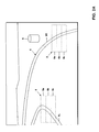
- Fig. 1 schematically represents a motor vehicle 1 equipped with a night-view system, said vehicle 1 moving on a road 5.
- Fig. 1 also shows a range of detection 2 of a night-view sensor of the night-view system, said range of detection 2 being illustrated by a dashed line.
- the range of detection 2 covers both a left road edge 5L and a right road edge 5R.
- the range of detection 2 extends forward from the vehicle 1 and therefore covers the vehicle environment in the direction of movement of the vehicle 1.
- the night-view sensor is preferably installed at a position which allows for a good coverage of the area in front of the vehicle 1, e.g. close to an upper position of the windshield, close to the rear view mirror or the sun visor. These positions allow for a field of view which is very similar to the driver's natural field of view.
- Figs. 2A and 2B show exemplary video images as provided by the night-view system of the vehicle 1, i.e. night-view images. It should be understood that in the night-view system as explained in the following, actually a sequence of images is continuously provided. That is to say, the video image actually comprises a sequence of images, which are evaluated and displayed in real time.
- the exemplary night-view image of Fig. 2A shows the road 5 which is bounded by the left road edge 5L and the right road edge 5R. Further, the image includes an object 6, which in the illustrated example is near the right road edge 5R.
- the night-view image will typically have the form of a grayscale representation or the like, in which the structures as schematically represented the figure are contrasts between different shades of gray or other color.
- the contrasts may in the night-view image be very weak and may vary from the contrasts as present in an image detected in the visible range of the electromagnetic spectrum. Therefore, operation of the night-view system involves detecting, i.e. identifying, the course of the road 5 in the night-view image and displaying the detected course of the road 5 superposed onto the night-view image so as to facilitate orientation in the night-view image.
- the course of the road 5 is identified using the contrasts due to the left road edge 5L and due to the right road edge 5R.
- this may be displayed in form of lines representing the left road edge 5L and right road edge 5R, or in the form of a solid surface representing the area between the left road edge 5L and the right road edge 5R, e.g. using a color which provides a sufficient contrast with respect to the grayscale representation of the night-view image.
- displaying only the left road edges may be advantageous as it does not "hide” any image information contained in the area between the left road edge 5L and the right road edge 5R, for example due to an obstacle on the road.
- the night-view image may also be evaluated so as to automatically detect additional objects, such as the object 6 illustrated in Fig. 2A. If an object is detected on or near the course of the road 5, the object may be highlighted and/or a warning may be provided to the driver, e.g. by means of an acoustical signal.
- detecting the course of the road 5 in the night-view image and highlighting the course of the road by superposing the detected course of the road onto the night-view image allows for better distinguishing between the relevant objects and the background of the night-view image. Further, orientation in the night-view image is facilitated. This is particularly advantageous in case of night-view images detected by means of a far-infrared sensor which provides contrasts which are significantly different from those as present in images detected in the visible range of the electromagnetic spectrum.
- detecting the course of the road 5 involves in a first stage processing the night-view image on the basis of contrast information.
- this is accomplished using evaluation windows 8 having multiple evaluation rows 8a, 8b, 8c and by suitably filtering the image data, e.g. using Kalman filters.
- the contrast due to the left road edge 5L and right road edge 5R can be enhanced and the effects due to the movements of the vehicle on the road 5 can be taken into account.
- evaluation windows 8 which are placed in areas of the night-view image where the road edges are to be expected, the evaluation can be simplified and the speed of evaluation can be increased.
- the evaluation windows 8 constitute portions of the night-view image in which relevant contrasts for detecting the course of the road 5 are expected.
- the size of the evaluation windows 8 is smaller than the overall size of the night-view image, evaluation time as compared to an evaluation of the entire night-view image can be reduced and/or the resolution of evaluation can be increased without adversely affecting the performance.
- suitable positions of the evaluation windows 8 are the lower left portion and the lower right portion of the night-view image.
- the evaluation windows have a generally rectangular shape.
- the evaluation windows are preferably subdivided into evaluation rows 8a, 8b, 8c, which extend in the horizontal direction of the night-view image.
- the use of such horizontally extending evaluation rows provides particular advantages as to the detection of substantially vertical structure such as the road edges 5L, 5R.
- contrast information in the night-view image provides poor results as the contrasts are insufficient, or may even be impossible, e.g. when the course of the road passes a peak which means that a portion of the left road edge 5L or the right road edge 5R is located beneath the peak and unavailable for evaluation.
- Other situations which adversely affect the detection of the left road edge 5L and the right road edge 5R on the basis of contrast information are the presence of crossings or junctions in the course of the road 5 or abrupt variations of the width of the road 5. Further, disturbances can be caused by changes in the surface of the road due to damage or different materials.
- the operating method and night-view system as described herein additionally involve using information on the course of the road as provided by a navigation device or navigation system of the vehicle when detecting the course of the road in the night-view image.
- the additional information may be used to adjust the sizes and/or positions of the evaluation windows 8.
- Fig. 2B schematically illustrates a further example of a night-view image, similar to that of Fig. 2A.
- the course of the road 5 includes a junction.
- the appearance of the structures in the night-view image is more complicated than in the case of Fig. 2A, where no junction is present in the course of the road 5.
- the number of road edges is effectively increased.
- the method as proposed herein includes taking into account information on the course of the road 5 as provided by a navigation device, in particular on the presence of a junction or crossing as illustrated in Fig. 2B.
- the evaluation can be adapted to the presence of the junction, for example by including additional evaluation windows 8 so as to detect additional road edges. Further, the sizes and/or positions of the evaluation windows 8 can be adjusted according to the information on the course of the road 5 as received from the navigation device.
- a height information on the course of the road 5 and/or information on the width of the road 5 is taken into account when evaluating the night-view image.
- variations of the height or road width in the course of the road 5 will influence the appearance of the course of the road 5 in the night-view image. For example, there may be perspective distortions, or the course of the road 5 may "disappear" beyond a peak.
- this is taken into account during evaluation of the night-view image.
- this is accomplished by calculating an expected course of the road 5 using the information as received from the navigation device and comparing the expected course of the road with the structures as detected in the night-view image.
- the expected course of the road 5 may serve as a basis for positioning the evaluation windows 8.
- road edges are detected in the night-view image, it is possible to match these detected road edges with the expected course of the road 5. That is to say, the expected structures are brought into alignment with the features detected in the night-view image. This significantly increases the accuracy of detection as the expected course of the road is less susceptible to disturbances. A nervous appearance of the detected course of the road 5 as displayed is avoided and it is thus possible for the driver to reliably recognize objects near or on the course of the road 5, such as the object 6 illustrated in Fig. 2A.
- the orientation or attitude of the vehicle 1 moving on the road 5 may change. That is to say, there may be an inclination of the vehicle 1 in the longitudinal or lateral direction and there may be different orientations of the vehicle 1 with respect to the course of the road, which influences the appearance of the night-view image. Accordingly, preferably also information on the orientation and/or attitude of the vehicle is taken into account during evaluation of the night-view image. This may be accomplished as explained above by comparing and matching the expected course of the road with features of the night-view image.
- the evaluation also takes into account a user-selected navigation route.
- future navigation movements of the vehicle can be anticipated in the evaluation, e.g. by assigning a higher priority to a region of the night-view image into which the vehicle is expected to move when following the selected navigation route.
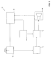
- Fig. 3 shows a block diagram schematically representing a night-view system 10 operating according to the principles as explained above.
- the night-view system 10 comprises a night-view sensor 12, which preferably operates in the far-infrared range and/or the near-infrared range of the electromagnetic spectrum, a video processing device 14, and a display device 20.
- the night-view sensor 12 provides a video signal representative of the night-view image to the video processing device 14. Further, a video signal representative of the night-view image is provided to the display device 20.
- the display device 20 may be a so-called head-up display which projects an image onto the windscreen of the vehicle.
- the night-view system 10 comprises a data processing device 13 which is connected to a navigation device 15 so as to receive an information signal.
- the information signal received from the navigation device 15 includes information on the position of the vehicle relative to the course of the road on which the vehicle moves, a height information of the course of the road, information on the presence of crossings or junctions in the course of the road, information on the width of the road, information on the attitude of the vehicle, and information on a user-selected navigation route stored in the navigation device 15.
- the navigation device 15 may be a component of the night-view system 10 or may be an external component, e.g. a part of a navigation system of a vehicle or a portable navigation system.
- the navigation device 15 preferably includes a satellite navigation function, e.g. a GPS function, which allows for accurately determining the position of the vehicle in a digital map representation.
- the digital map representation is stored in a suitable storage device of the navigation device 15, such as a hard disc device, a CD-ROM device, a DVD device or other suitable memory device.
- the digital map representation includes the above-mentioned information on the course of the road, in particular on the presence of crossings or junctions, the height information and information on the width of the road.
- the navigation device 15 also comprises orientation and attitude sensors, such as a gyroscopic device, which provide information on the orientation and attitude of the vehicle.
- the information signal is received by the data processing device 13 and processed so as to be suitably conditioned to be used in processing the night-view image provided by the night-view sensor 12. From the data processing device 13, a corresponding conditioned information signal is supplied to the video processing device 14, which also receives the video signal from the night-view sensor 12.
- the video processing device 14 performs the essential evaluation of the night-view image, taking into account the information as provided by the navigation device 15 and conditioned by the data processing device 13. As an output, the video processing device 14 provides a signal representative of the detected course of the road which is supplied to the display device 20 so as to be displayed together with the night-view image.
- the night-view image as provided by the night-view sensor 12 and the detected course of the road as provided by the video processing device 14 are superposed so as to generate a single image representation which offers a significantly improved orientation as compared to the bare night-view image.
- the display device 20 is configured as a multipurpose display commonly used by the navigation device 15 and the night-view system 10. That is to say, the display device 20 also receives an input signal directly from the navigation device 15 so as to display navigation information such as driver instructions or traffic information.
- the common display device it is not required to provide multiple displays in the vehicle, thereby reducing hardware requirements and increasing the driver's comfort.
- the video processing device 14 also performs additional image analysis functions.
- the night-view image may be analyzed so as to identify objects which are located near or on the detected course of the road.
- such objects may be animals, humans or other vehicles.
- the video processing device initiates a warning if such an object is detected.
- the warning may involve highlighting the detected object in the displayed night-view image and/or providing an acoustical warning.
- the night-view system is connected to a loudspeaker device 30 which outputs the acoustical warning.
- the loudspeaker device 30 may be a component of the night-view system 10 or may be a separate component, e.g. part of a vehicle entertainment system.
- the loudspeaker device 30 may also be used for acoustical output of said navigation information.
- core components of the night-view system 10 are the data processing device 13, the video processing device 14, the night-view sensor 12, and the display device 20. However, it is not necessary that these components are specifically dedicated to the night-view system 10. Rather, they may be commonly used by other vehicle systems, such as a navigation system, an entertainment system, a security system, or a multimedia system. That is to say, the night-view system 10 may be integrated with other vehicle systems, there by reducing hardware outlay and associated costs.
- the data processing device 13 and the video processing device 14 may actually be implemented by means of a single microprocessor.
- the single microprocessor may also be used to perform processing tasks of the navigation device 15.
- Fig. 4 shows a flowchart schematically representing a method of operating a night-view system according to the principles as described above.
- the method generally involves processing of the night-view image so as to detect the course of the road on which the vehicle moves, said processing being accomplished taking into account information on the course of the road as provided by the navigation device 15.
- the video image i.e. night-view image
- the image preferably covers the area in front of the vehicle, in the direction in which the vehicle moves, as this area is of particular relevance to the driver.
- the image is recorded in the far-infrared range, near-infrared range, or a combination thereof. It is to be understood that the video image actually comprises a sequence of images, which are recorded and further processed in real time.
- step 120 information is retrieved from the navigation device, which relates to the course of the road on which the vehicle moves.
- the information includes information on the vehicle position relative to the course of the road, information on the presence of junctions or crossings in the course of the road, information on the width of the road, and a height information of the course of the road. Further, the information includes data on the attitude and orientation of the vehicle and/or information on a user-selected navigation route.
- the retrieved information is conditioned for the use in processing of the video image.
- step 130 an initial processing of the video image is carried out, which is essentially based on contrast information.
- the information received from the navigation device is taken into account by suitably adjusting and positioning evaluation windows as described in connection with Figs. 2A and 2B.
- an expected course of the road is calculated on the basis of the information received from the navigation device.
- the calculation is based on the general principles of geometric optics and the field of view of the night-view sensor.
- the expected course of the road is matched and compared with structures identified in said initial processing.
- a road edge identified in step 130 may be aligned with a calculated expected road edge.
- the evaluation windows are adjusted and/or repositioned, and a refined processing of the video image on the basis of contrast information is carried out so as to verify and supplement the results of the initial processing.
- a detected course of the road is output on the basis of the results of the initial and refined processing. Even in the case that no structures could be identified in the initial and refined processing, it is possible to output a course of the road on the basis of the expected course of the road.
- step 150 the video image and the detected course of the road are displayed to the driver.
- the detected course of the road is superposed onto the video image so as to facilitate orientation, e.g. using a head-up display.
- the video image is also processed so as to identify objects near or on the course of the road.
- the detected objects are highlighted in the displayed video image and/or an acoustical warning is provided.
- step 150 the method is repeated so as to continuously evaluate and display the video image and the detected course of the road. In this respect, it is advantageous to recursively utilize the results of previous evaluation cycles.
- the type of night-view sensor and/or the type of navigation device may be selected according to the specific requirements. Further, a variety of suitable image processing techniques may be adopted so as to be used within the described method.
- the navigation device may be an integrated component of the night-view system or may be a separate component, for example a conventional navigation system or a part thereof.
- the navigation device may include a satellite navigation function. However, it is also possible to utilize other navigation systems, which allow for determining the position of the vehicle with respect to a digital map representation. Different types of display devices may be used, depending on the type of vehicle and other design aspects. Further, the night-view system and navigation device may be integrated within a multimedia system of the vehicle.
Landscapes
- Engineering & Computer Science (AREA)
- Multimedia (AREA)
- Mechanical Engineering (AREA)
- Physics & Mathematics (AREA)
- General Physics & Mathematics (AREA)
- Remote Sensing (AREA)
- Radar, Positioning & Navigation (AREA)
- Navigation (AREA)
- Traffic Control Systems (AREA)
- Fittings On The Vehicle Exterior For Carrying Loads, And Devices For Holding Or Mounting Articles (AREA)
- Closed-Circuit Television Systems (AREA)
- Steering Control In Accordance With Driving Conditions (AREA)
- Lighting Device Outwards From Vehicle And Optical Signal (AREA)
Priority Applications (7)
| Application Number | Priority Date | Filing Date | Title |
|---|---|---|---|
| EP06018338A EP1894779B1 (de) | 2006-09-01 | 2006-09-01 | Verfahren zum Betreiben eines Nachtsichtsystems in einem Kraftfahrzeug und entsprechendes Nachtsichtsystem |
| DE602006010699T DE602006010699D1 (de) | 2006-09-01 | 2006-09-01 | Verfahren zum Betreiben eines Nachtsichtsystems in einem Kraftfahrzeug und entsprechendes Nachtsichtsystem |
| AT06018338T ATE449703T1 (de) | 2006-09-01 | 2006-09-01 | Verfahren zum betreiben eines nachtsichtsystems in einem kraftfahrzeug und entsprechendes nachtsichtsystem |
| CA2598165A CA2598165C (en) | 2006-09-01 | 2007-08-21 | Method of operating a night-view system in a vehicle and corresponding night-view system |
| JP2007223713A JP5537769B2 (ja) | 2006-09-01 | 2007-08-30 | 車両内のナイトビューシステムを動作させる方法および対応するナイトビューシステム |
| KR1020070088032A KR101433837B1 (ko) | 2006-09-01 | 2007-08-31 | 차량의 나이트-뷰 시스템 동작 방법 및 대응하는 나이트-뷰시스템 |
| CN2007101478699A CN101135570B (zh) | 2006-09-01 | 2007-08-31 | 在车辆中操作夜视系统的方法及对应的夜视系统 |
Applications Claiming Priority (1)
| Application Number | Priority Date | Filing Date | Title |
|---|---|---|---|
| EP06018338A EP1894779B1 (de) | 2006-09-01 | 2006-09-01 | Verfahren zum Betreiben eines Nachtsichtsystems in einem Kraftfahrzeug und entsprechendes Nachtsichtsystem |
Publications (2)
| Publication Number | Publication Date |
|---|---|
| EP1894779A1 true EP1894779A1 (de) | 2008-03-05 |
| EP1894779B1 EP1894779B1 (de) | 2009-11-25 |
Family
ID=37731375
Family Applications (1)
| Application Number | Title | Priority Date | Filing Date |
|---|---|---|---|
| EP06018338A Active EP1894779B1 (de) | 2006-09-01 | 2006-09-01 | Verfahren zum Betreiben eines Nachtsichtsystems in einem Kraftfahrzeug und entsprechendes Nachtsichtsystem |
Country Status (7)
| Country | Link |
|---|---|
| EP (1) | EP1894779B1 (de) |
| JP (1) | JP5537769B2 (de) |
| KR (1) | KR101433837B1 (de) |
| CN (1) | CN101135570B (de) |
| AT (1) | ATE449703T1 (de) |
| CA (1) | CA2598165C (de) |
| DE (1) | DE602006010699D1 (de) |
Cited By (3)
| Publication number | Priority date | Publication date | Assignee | Title |
|---|---|---|---|---|
| US8510200B2 (en) | 2011-12-02 | 2013-08-13 | Spireon, Inc. | Geospatial data based assessment of driver behavior |
| WO2014027131A1 (en) * | 2012-08-14 | 2014-02-20 | Nokia Corporation | Low light vision assistance |
| CN111993992A (zh) * | 2015-04-10 | 2020-11-27 | 麦克赛尔株式会社 | 投射型显示装置 |
Families Citing this family (15)
| Publication number | Priority date | Publication date | Assignee | Title |
|---|---|---|---|---|
| US20100253595A1 (en) * | 2009-04-02 | 2010-10-07 | Gm Global Technology Operations, Inc. | Virtual controls and displays by laser projection |
| US10169822B2 (en) | 2011-12-02 | 2019-01-01 | Spireon, Inc. | Insurance rate optimization through driver behavior monitoring |
| CN103182985B (zh) * | 2011-12-27 | 2016-08-17 | 大陆汽车电子(长春)有限公司 | 利用图像处理装置的车辆安全装置和车辆安全控制方法 |
| JP5464219B2 (ja) * | 2012-02-03 | 2014-04-09 | 株式会社デンソー | 車両用ヘッドアップディスプレイ装置 |
| JP5464222B2 (ja) * | 2012-02-08 | 2014-04-09 | 株式会社デンソー | 車両用ヘッドアップディスプレイ装置 |
| US9779379B2 (en) | 2012-11-05 | 2017-10-03 | Spireon, Inc. | Container verification through an electrical receptacle and plug associated with a container and a transport vehicle of an intermodal freight transport system |
| US8933802B2 (en) | 2012-11-05 | 2015-01-13 | Spireon, Inc. | Switch and actuator coupling in a chassis of a container associated with an intermodal freight transport system |
| US9779449B2 (en) | 2013-08-30 | 2017-10-03 | Spireon, Inc. | Veracity determination through comparison of a geospatial location of a vehicle with a provided data |
| US20150186991A1 (en) | 2013-12-31 | 2015-07-02 | David M. Meyer | Creditor alert when a vehicle enters an impound lot |
| US9551788B2 (en) | 2015-03-24 | 2017-01-24 | Jim Epler | Fleet pan to provide measurement and location of a stored transport item while maximizing space in an interior cavity of a trailer |
| CN106403963A (zh) * | 2016-08-19 | 2017-02-15 | 东风汽车公司 | 一种实现车载实景导航的夜视系统 |
| DE102018216984A1 (de) * | 2018-10-04 | 2020-04-09 | Robert Bosch Gmbh | Umfelderfassungssystem für Kraftfahrzeuge |
| WO2020126396A1 (en) * | 2018-12-17 | 2020-06-25 | Orlaco Products B.V. | Camera mirror system with ir led night vision system |
| CN111460865B (zh) * | 2019-01-22 | 2024-03-05 | 斑马智行网络(香港)有限公司 | 辅助驾驶方法、辅助驾驶系统、计算设备及存储介质 |
| CN110356395A (zh) * | 2019-06-25 | 2019-10-22 | 武汉格罗夫氢能汽车有限公司 | 一种车辆车道保持方法、设备及存储设备 |
Citations (4)
| Publication number | Priority date | Publication date | Assignee | Title |
|---|---|---|---|---|
| FR2785434A1 (fr) * | 1998-11-03 | 2000-05-05 | Renault | Procede d'aide a la conduite d'un vehicule et dispositif de mise en oeuvre |
| EP1024057A2 (de) * | 1999-01-26 | 2000-08-02 | Mazda Motor Corporation | Kraftfahrzeug-Anzeigevorrichtung |
| DE19950033A1 (de) * | 1999-10-16 | 2001-05-03 | Bayerische Motoren Werke Ag | Kameravorrichtung für Fahrzeuge |
| US20040066376A1 (en) * | 2000-07-18 | 2004-04-08 | Max Donath | Mobility assist device |
Family Cites Families (10)
| Publication number | Priority date | Publication date | Assignee | Title |
|---|---|---|---|---|
| JPH08253059A (ja) * | 1995-03-17 | 1996-10-01 | Honda Motor Co Ltd | 車両用運転支援システム |
| JPH08263784A (ja) * | 1995-03-23 | 1996-10-11 | Honda Motor Co Ltd | 道路状況認識装置 |
| JP2001101596A (ja) * | 1999-09-27 | 2001-04-13 | Mazda Motor Corp | 車両の表示装置 |
| JP3883033B2 (ja) * | 2000-08-03 | 2007-02-21 | マツダ株式会社 | 車両用表示装置 |
| CN1540286A (zh) * | 2003-04-25 | 2004-10-27 | 王舜清 | 多功能实时交通安全管理装置及方法 |
| CN1458014A (zh) * | 2003-05-30 | 2003-11-26 | 陈湘云 | 车载夜视辅助装置 |
| JP2005157731A (ja) * | 2003-11-26 | 2005-06-16 | Nissan Motor Co Ltd | 車線認識装置および車線認識方法 |
| DE102004036566A1 (de) * | 2004-07-28 | 2006-03-23 | Robert Bosch Gmbh | Nachtsichtgerät |
| CN1664620A (zh) * | 2005-04-04 | 2005-09-07 | 戴宏 | 一种机动车、船夜视装置 |
| JP2007011994A (ja) * | 2005-07-04 | 2007-01-18 | Toyota Motor Corp | 道路認識装置 |
-
2006
- 2006-09-01 DE DE602006010699T patent/DE602006010699D1/de active Active
- 2006-09-01 AT AT06018338T patent/ATE449703T1/de not_active IP Right Cessation
- 2006-09-01 EP EP06018338A patent/EP1894779B1/de active Active
-
2007
- 2007-08-21 CA CA2598165A patent/CA2598165C/en active Active
- 2007-08-30 JP JP2007223713A patent/JP5537769B2/ja active Active
- 2007-08-31 CN CN2007101478699A patent/CN101135570B/zh active Active
- 2007-08-31 KR KR1020070088032A patent/KR101433837B1/ko active IP Right Grant
Patent Citations (4)
| Publication number | Priority date | Publication date | Assignee | Title |
|---|---|---|---|---|
| FR2785434A1 (fr) * | 1998-11-03 | 2000-05-05 | Renault | Procede d'aide a la conduite d'un vehicule et dispositif de mise en oeuvre |
| EP1024057A2 (de) * | 1999-01-26 | 2000-08-02 | Mazda Motor Corporation | Kraftfahrzeug-Anzeigevorrichtung |
| DE19950033A1 (de) * | 1999-10-16 | 2001-05-03 | Bayerische Motoren Werke Ag | Kameravorrichtung für Fahrzeuge |
| US20040066376A1 (en) * | 2000-07-18 | 2004-04-08 | Max Donath | Mobility assist device |
Cited By (3)
| Publication number | Priority date | Publication date | Assignee | Title |
|---|---|---|---|---|
| US8510200B2 (en) | 2011-12-02 | 2013-08-13 | Spireon, Inc. | Geospatial data based assessment of driver behavior |
| WO2014027131A1 (en) * | 2012-08-14 | 2014-02-20 | Nokia Corporation | Low light vision assistance |
| CN111993992A (zh) * | 2015-04-10 | 2020-11-27 | 麦克赛尔株式会社 | 投射型显示装置 |
Also Published As
| Publication number | Publication date |
|---|---|
| CN101135570A (zh) | 2008-03-05 |
| CN101135570B (zh) | 2013-05-08 |
| ATE449703T1 (de) | 2009-12-15 |
| JP2008056233A (ja) | 2008-03-13 |
| CA2598165A1 (en) | 2008-03-01 |
| DE602006010699D1 (de) | 2010-01-07 |
| EP1894779B1 (de) | 2009-11-25 |
| KR101433837B1 (ko) | 2014-08-27 |
| JP5537769B2 (ja) | 2014-07-02 |
| KR20080020956A (ko) | 2008-03-06 |
| CA2598165C (en) | 2011-04-05 |
Similar Documents
| Publication | Publication Date | Title |
|---|---|---|
| CA2598165C (en) | Method of operating a night-view system in a vehicle and corresponding night-view system | |
| US10733462B2 (en) | Travel assistance device and computer program | |
| US8354944B2 (en) | Night vision device | |
| US20080195315A1 (en) | Movable-Body Navigation Information Display Method and Movable-Body Navigation Information Display Unit | |
| CN103140377B (zh) | 用于在显示装置上显示图像的方法和驾驶员辅助系统 | |
| US8089512B2 (en) | Driving support device, driving support method and computer program | |
| US9267808B2 (en) | Visual guidance system | |
| US8878932B2 (en) | System and method for detecting the surrounding environment of a motor vehicle using as adjustable infrared night vision system | |
| EP2928182B1 (de) | Bordeigenes bildverarbeitungssystem | |
| CN110419063A (zh) | Ar显示装置和ar显示方法 | |
| JP2005182306A (ja) | 車両用表示装置 | |
| JP2008280026A (ja) | 運転支援装置 | |
| CN106515583A (zh) | 驾驶者信息方法 | |
| CN109415018B (zh) | 用于数字后视镜的方法和控制单元 | |
| US10996469B2 (en) | Method and apparatus for providing driving information of vehicle, and recording medium | |
| JP2007102798A (ja) | 車両周辺監視システム | |
| US11308721B2 (en) | System for detecting the face of a driver and method associated thereto | |
| US20210327113A1 (en) | Method and arrangement for producing a surroundings map of a vehicle, textured with image information, and vehicle comprising such an arrangement | |
| JP2005202787A (ja) | 車両用表示装置 | |
| US11390215B2 (en) | Assistance system for a vehicle | |
| US11967007B2 (en) | Vehicle surroundings information displaying system and vehicle surroundings information displaying method | |
| JP2006273190A (ja) | 車載用ナビゲーション装置 | |
| US10864856B2 (en) | Mobile body surroundings display method and mobile body surroundings display apparatus | |
| JP7253708B2 (ja) | 情報処理装置、車両及び情報処理方法 | |
| JP2006276964A (ja) | 車両用表示装置 |
Legal Events
| Date | Code | Title | Description |
|---|---|---|---|
| PUAI | Public reference made under article 153(3) epc to a published international application that has entered the european phase |
Free format text: ORIGINAL CODE: 0009012 |
|
| 17P | Request for examination filed |
Effective date: 20070703 |
|
| AK | Designated contracting states |
Kind code of ref document: A1 Designated state(s): AT BE BG CH CY CZ DE DK EE ES FI FR GB GR HU IE IS IT LI LT LU LV MC NL PL PT RO SE SI SK TR |
|
| AX | Request for extension of the european patent |
Extension state: AL BA HR MK YU |
|
| 17Q | First examination report despatched |
Effective date: 20080218 |
|
| AKX | Designation fees paid |
Designated state(s): AT BE BG CH CY CZ DE DK EE ES FI FR GB GR HU IE IS IT LI LT LU LV MC NL PL PT RO SE SI SK TR |
|
| GRAP | Despatch of communication of intention to grant a patent |
Free format text: ORIGINAL CODE: EPIDOSNIGR1 |
|
| GRAS | Grant fee paid |
Free format text: ORIGINAL CODE: EPIDOSNIGR3 |
|
| GRAA | (expected) grant |
Free format text: ORIGINAL CODE: 0009210 |
|
| AK | Designated contracting states |
Kind code of ref document: B1 Designated state(s): AT BE BG CH CY CZ DE DK EE ES FI FR GB GR HU IE IS IT LI LT LU LV MC NL PL PT RO SE SI SK TR |
|
| REG | Reference to a national code |
Ref country code: GB Ref legal event code: FG4D |
|
| REG | Reference to a national code |
Ref country code: CH Ref legal event code: EP |
|
| REG | Reference to a national code |
Ref country code: IE Ref legal event code: FG4D |
|
| REF | Corresponds to: |
Ref document number: 602006010699 Country of ref document: DE Date of ref document: 20100107 Kind code of ref document: P |
|
| REG | Reference to a national code |
Ref country code: NL Ref legal event code: VDEP Effective date: 20091125 |
|
| LTIE | Lt: invalidation of european patent or patent extension |
Effective date: 20091125 |
|
| PG25 | Lapsed in a contracting state [announced via postgrant information from national office to epo] |
Ref country code: PT Free format text: LAPSE BECAUSE OF FAILURE TO SUBMIT A TRANSLATION OF THE DESCRIPTION OR TO PAY THE FEE WITHIN THE PRESCRIBED TIME-LIMIT Effective date: 20100325 Ref country code: SE Free format text: LAPSE BECAUSE OF FAILURE TO SUBMIT A TRANSLATION OF THE DESCRIPTION OR TO PAY THE FEE WITHIN THE PRESCRIBED TIME-LIMIT Effective date: 20091125 Ref country code: FI Free format text: LAPSE BECAUSE OF FAILURE TO SUBMIT A TRANSLATION OF THE DESCRIPTION OR TO PAY THE FEE WITHIN THE PRESCRIBED TIME-LIMIT Effective date: 20091125 Ref country code: IS Free format text: LAPSE BECAUSE OF FAILURE TO SUBMIT A TRANSLATION OF THE DESCRIPTION OR TO PAY THE FEE WITHIN THE PRESCRIBED TIME-LIMIT Effective date: 20100325 Ref country code: LT Free format text: LAPSE BECAUSE OF FAILURE TO SUBMIT A TRANSLATION OF THE DESCRIPTION OR TO PAY THE FEE WITHIN THE PRESCRIBED TIME-LIMIT Effective date: 20091125 |
|
| PG25 | Lapsed in a contracting state [announced via postgrant information from national office to epo] |
Ref country code: PL Free format text: LAPSE BECAUSE OF FAILURE TO SUBMIT A TRANSLATION OF THE DESCRIPTION OR TO PAY THE FEE WITHIN THE PRESCRIBED TIME-LIMIT Effective date: 20091125 Ref country code: CY Free format text: LAPSE BECAUSE OF FAILURE TO SUBMIT A TRANSLATION OF THE DESCRIPTION OR TO PAY THE FEE WITHIN THE PRESCRIBED TIME-LIMIT Effective date: 20091125 Ref country code: SI Free format text: LAPSE BECAUSE OF FAILURE TO SUBMIT A TRANSLATION OF THE DESCRIPTION OR TO PAY THE FEE WITHIN THE PRESCRIBED TIME-LIMIT Effective date: 20091125 Ref country code: LV Free format text: LAPSE BECAUSE OF FAILURE TO SUBMIT A TRANSLATION OF THE DESCRIPTION OR TO PAY THE FEE WITHIN THE PRESCRIBED TIME-LIMIT Effective date: 20091125 |
|
| PG25 | Lapsed in a contracting state [announced via postgrant information from national office to epo] |
Ref country code: AT Free format text: LAPSE BECAUSE OF FAILURE TO SUBMIT A TRANSLATION OF THE DESCRIPTION OR TO PAY THE FEE WITHIN THE PRESCRIBED TIME-LIMIT Effective date: 20091125 Ref country code: BE Free format text: LAPSE BECAUSE OF FAILURE TO SUBMIT A TRANSLATION OF THE DESCRIPTION OR TO PAY THE FEE WITHIN THE PRESCRIBED TIME-LIMIT Effective date: 20091125 |
|
| PG25 | Lapsed in a contracting state [announced via postgrant information from national office to epo] |
Ref country code: ES Free format text: LAPSE BECAUSE OF FAILURE TO SUBMIT A TRANSLATION OF THE DESCRIPTION OR TO PAY THE FEE WITHIN THE PRESCRIBED TIME-LIMIT Effective date: 20100308 Ref country code: DK Free format text: LAPSE BECAUSE OF FAILURE TO SUBMIT A TRANSLATION OF THE DESCRIPTION OR TO PAY THE FEE WITHIN THE PRESCRIBED TIME-LIMIT Effective date: 20091125 Ref country code: EE Free format text: LAPSE BECAUSE OF FAILURE TO SUBMIT A TRANSLATION OF THE DESCRIPTION OR TO PAY THE FEE WITHIN THE PRESCRIBED TIME-LIMIT Effective date: 20091125 Ref country code: NL Free format text: LAPSE BECAUSE OF FAILURE TO SUBMIT A TRANSLATION OF THE DESCRIPTION OR TO PAY THE FEE WITHIN THE PRESCRIBED TIME-LIMIT Effective date: 20091125 Ref country code: RO Free format text: LAPSE BECAUSE OF FAILURE TO SUBMIT A TRANSLATION OF THE DESCRIPTION OR TO PAY THE FEE WITHIN THE PRESCRIBED TIME-LIMIT Effective date: 20091125 Ref country code: BG Free format text: LAPSE BECAUSE OF FAILURE TO SUBMIT A TRANSLATION OF THE DESCRIPTION OR TO PAY THE FEE WITHIN THE PRESCRIBED TIME-LIMIT Effective date: 20100225 |
|
| PG25 | Lapsed in a contracting state [announced via postgrant information from national office to epo] |
Ref country code: SK Free format text: LAPSE BECAUSE OF FAILURE TO SUBMIT A TRANSLATION OF THE DESCRIPTION OR TO PAY THE FEE WITHIN THE PRESCRIBED TIME-LIMIT Effective date: 20091125 Ref country code: CZ Free format text: LAPSE BECAUSE OF FAILURE TO SUBMIT A TRANSLATION OF THE DESCRIPTION OR TO PAY THE FEE WITHIN THE PRESCRIBED TIME-LIMIT Effective date: 20091125 |
|
| PLBE | No opposition filed within time limit |
Free format text: ORIGINAL CODE: 0009261 |
|
| STAA | Information on the status of an ep patent application or granted ep patent |
Free format text: STATUS: NO OPPOSITION FILED WITHIN TIME LIMIT |
|
| PG25 | Lapsed in a contracting state [announced via postgrant information from national office to epo] |
Ref country code: GR Free format text: LAPSE BECAUSE OF FAILURE TO SUBMIT A TRANSLATION OF THE DESCRIPTION OR TO PAY THE FEE WITHIN THE PRESCRIBED TIME-LIMIT Effective date: 20100226 |
|
| 26N | No opposition filed |
Effective date: 20100826 |
|
| PG25 | Lapsed in a contracting state [announced via postgrant information from national office to epo] |
Ref country code: IT Free format text: LAPSE BECAUSE OF FAILURE TO SUBMIT A TRANSLATION OF THE DESCRIPTION OR TO PAY THE FEE WITHIN THE PRESCRIBED TIME-LIMIT Effective date: 20091125 |
|
| PG25 | Lapsed in a contracting state [announced via postgrant information from national office to epo] |
Ref country code: MC Free format text: LAPSE BECAUSE OF NON-PAYMENT OF DUE FEES Effective date: 20100930 |
|
| REG | Reference to a national code |
Ref country code: CH Ref legal event code: PL |
|
| PG25 | Lapsed in a contracting state [announced via postgrant information from national office to epo] |
Ref country code: IE Free format text: LAPSE BECAUSE OF NON-PAYMENT OF DUE FEES Effective date: 20100901 Ref country code: CH Free format text: LAPSE BECAUSE OF NON-PAYMENT OF DUE FEES Effective date: 20100930 Ref country code: LI Free format text: LAPSE BECAUSE OF NON-PAYMENT OF DUE FEES Effective date: 20100930 |
|
| PG25 | Lapsed in a contracting state [announced via postgrant information from national office to epo] |
Ref country code: LU Free format text: LAPSE BECAUSE OF NON-PAYMENT OF DUE FEES Effective date: 20100901 Ref country code: HU Free format text: LAPSE BECAUSE OF FAILURE TO SUBMIT A TRANSLATION OF THE DESCRIPTION OR TO PAY THE FEE WITHIN THE PRESCRIBED TIME-LIMIT Effective date: 20100526 |
|
| PG25 | Lapsed in a contracting state [announced via postgrant information from national office to epo] |
Ref country code: TR Free format text: LAPSE BECAUSE OF FAILURE TO SUBMIT A TRANSLATION OF THE DESCRIPTION OR TO PAY THE FEE WITHIN THE PRESCRIBED TIME-LIMIT Effective date: 20091125 |
|
| PGFP | Annual fee paid to national office [announced via postgrant information from national office to epo] |
Ref country code: FR Payment date: 20130919 Year of fee payment: 8 |
|
| REG | Reference to a national code |
Ref country code: FR Ref legal event code: ST Effective date: 20150529 |
|
| PG25 | Lapsed in a contracting state [announced via postgrant information from national office to epo] |
Ref country code: FR Free format text: LAPSE BECAUSE OF NON-PAYMENT OF DUE FEES Effective date: 20140930 |
|
| P01 | Opt-out of the competence of the unified patent court (upc) registered |
Effective date: 20230526 |
|
| PGFP | Annual fee paid to national office [announced via postgrant information from national office to epo] |
Ref country code: GB Payment date: 20230823 Year of fee payment: 18 |
|
| PGFP | Annual fee paid to national office [announced via postgrant information from national office to epo] |
Ref country code: DE Payment date: 20230822 Year of fee payment: 18 |