EP1891908B1 - Instrument chirurgical repérable avec extrémité remplaçable - Google Patents
Instrument chirurgical repérable avec extrémité remplaçable Download PDFInfo
- Publication number
- EP1891908B1 EP1891908B1 EP06017395A EP06017395A EP1891908B1 EP 1891908 B1 EP1891908 B1 EP 1891908B1 EP 06017395 A EP06017395 A EP 06017395A EP 06017395 A EP06017395 A EP 06017395A EP 1891908 B1 EP1891908 B1 EP 1891908B1
- Authority
- EP
- European Patent Office
- Prior art keywords
- instrument
- tracking
- medical
- marker
- markers
- Prior art date
- Legal status (The legal status is an assumption and is not a legal conclusion. Google has not performed a legal analysis and makes no representation as to the accuracy of the status listed.)
- Not-in-force
Links
Images
Classifications
-
- A—HUMAN NECESSITIES
- A61—MEDICAL OR VETERINARY SCIENCE; HYGIENE
- A61B—DIAGNOSIS; SURGERY; IDENTIFICATION
- A61B90/00—Instruments, implements or accessories specially adapted for surgery or diagnosis and not covered by any of the groups A61B1/00 - A61B50/00, e.g. for luxation treatment or for protecting wound edges
- A61B90/39—Markers, e.g. radio-opaque or breast lesions markers
-
- A—HUMAN NECESSITIES
- A61—MEDICAL OR VETERINARY SCIENCE; HYGIENE
- A61B—DIAGNOSIS; SURGERY; IDENTIFICATION
- A61B17/00—Surgical instruments, devices or methods
- A61B2017/0046—Surgical instruments, devices or methods with a releasable handle; with handle and operating part separable
-
- A—HUMAN NECESSITIES
- A61—MEDICAL OR VETERINARY SCIENCE; HYGIENE
- A61B—DIAGNOSIS; SURGERY; IDENTIFICATION
- A61B17/00—Surgical instruments, devices or methods
- A61B2017/0046—Surgical instruments, devices or methods with a releasable handle; with handle and operating part separable
- A61B2017/00473—Distal part, e.g. tip or head
-
- A—HUMAN NECESSITIES
- A61—MEDICAL OR VETERINARY SCIENCE; HYGIENE
- A61B—DIAGNOSIS; SURGERY; IDENTIFICATION
- A61B34/00—Computer-aided surgery; Manipulators or robots specially adapted for use in surgery
- A61B34/20—Surgical navigation systems; Devices for tracking or guiding surgical instruments, e.g. for frameless stereotaxis
- A61B2034/2046—Tracking techniques
- A61B2034/2055—Optical tracking systems
-
- A—HUMAN NECESSITIES
- A61—MEDICAL OR VETERINARY SCIENCE; HYGIENE
- A61B—DIAGNOSIS; SURGERY; IDENTIFICATION
- A61B34/00—Computer-aided surgery; Manipulators or robots specially adapted for use in surgery
- A61B34/20—Surgical navigation systems; Devices for tracking or guiding surgical instruments, e.g. for frameless stereotaxis
- A61B2034/2068—Surgical navigation systems; Devices for tracking or guiding surgical instruments, e.g. for frameless stereotaxis using pointers, e.g. pointers having reference marks for determining coordinates of body points
-
- A—HUMAN NECESSITIES
- A61—MEDICAL OR VETERINARY SCIENCE; HYGIENE
- A61B—DIAGNOSIS; SURGERY; IDENTIFICATION
- A61B90/00—Instruments, implements or accessories specially adapted for surgery or diagnosis and not covered by any of the groups A61B1/00 - A61B50/00, e.g. for luxation treatment or for protecting wound edges
- A61B90/39—Markers, e.g. radio-opaque or breast lesions markers
- A61B2090/3983—Reference marker arrangements for use with image guided surgery
-
- A—HUMAN NECESSITIES
- A61—MEDICAL OR VETERINARY SCIENCE; HYGIENE
- A61B—DIAGNOSIS; SURGERY; IDENTIFICATION
- A61B34/00—Computer-aided surgery; Manipulators or robots specially adapted for use in surgery
- A61B34/20—Surgical navigation systems; Devices for tracking or guiding surgical instruments, e.g. for frameless stereotaxis
Definitions
- the invention relates to a tracking medical instrument with a replaceable tip.
- the invention relates to a medical instrument with a handle and a functional section, wherein an arrangement of tracking markers is arranged on the instrument.
- Such instruments are intended for use in image-enhanced surgery, and the tracking markers are used to track the instrument by means of a medical tracking system and to identify the instrument by a medical navigation system.
- the position of the instrument, in particular its functional section (tip) can be located and tracked and the instrument displayed, for example, in spatial relation to previously determined patient data (from imaging methods, CT, MRI, etc.) on an image output (screen) to provide visual support to the surgeon in his work.
- a medical instrument can be divided into at least two parts and reassembled, wherein at least one tracking marker is arranged on each part.
- This divisibility results in an interchangeability of an instrument part, and thus there is the possibility of influencing the arrangement of the tracking markers of the instrument by the exchange of instrument parts.
- One or more tracking markers may then remain as they are on one part of the instrument, and when an exchange instrument part is combined with the remaining part of the instrument, a new marker arrangement is created, which in turn is characteristic of the new instrument.
- the invention thus obviates the need to provide complete new marker arrangements for different instruments.
- a first part of the instrument comprises the functional section, for example the instrument tip, which may be differently designed and adapted to different operations (eg, pointer tip, tweezers, scalpel blade) depending on the instrument and a second part of the instrument includes at least a part of the handle (the instrument is so divisible in the handle).
- the functional section for example the instrument tip, which may be differently designed and adapted to different operations (eg, pointer tip, tweezers, scalpel blade) depending on the instrument and a second part of the instrument includes at least a part of the handle (the instrument is so divisible in the handle).
- the overall geometry of the tracking marker or the tracking marker group of the functional section along with the tracking marker or the Tracking marker group of the distal part are characteristic of an instrument composition and serve its individual recognition.
- the individual recognizability is ensured if, for identical geometries of the distal part, the position of the tracking marker or the positions of the tracking marker group differ at least in the axial position; in general, a change of the axial and the radial position can be used for the variability of the geometries.
- a tracking marker on the first instrument part and a further tracking marker on the second instrument part
- a tracking marker can also be arranged on the first instrument part and a tracking marker group with two or more tracking markers on the second instrument part.
- the first instrument part may also have a plurality of tracking markers, it is only important that the or the tracking markers for the first instrument part have a unique arrangement that is assignable to this instrument part.
- connection in particular one or more of the following types of connection comprises: a screw thread connection with positive or frictional engagement means between the first and second instrument part; a snap connection with positive or frictional engaging means between the first and second instrument panels; a connector with positive or frictional engagement means between the first and second instrument part.
- the tracking markers of a medical instrument can be used to track the instrument by means of a medical tracking system and to identify the instrument by a medical navigation system.
- the invention further comprises a medical instrument set with at least two instruments, as described above in various embodiments have been.
- two instruments does not necessarily mean that there must be two first instrument parts and two second instrument parts; on the contrary, the instruments may consist of different first parts of the instrument, each comprising the functional part, and the same or the same part of the second part Handle include, be built up.
- a single second instrument part, to which a plurality of first instrument parts can be attached interchangeably, is sufficient to provide a set of instruments according to the invention.
- the invention helps a user, for example a surgeon, to adapt his instrument to the situation-specific requirements. It is only necessary to exchange the front part of an instrument to make a completely different instrument, with the new front part (first instrument part or Distalteil) with its reference marker or its reference markers together with the rear instrument part (second instrument part or Proximalteil) recognized by the navigation system due to the configuration or arrangement of all markers on the instrument. For this, the various combinations can be stored in the navigation system. Upon detection of a combination, the newly combined instrument can then be uniquely identified and assigned, and the navigation system no longer needs to be separately informed as to which instrument is being used.
- the invention makes it possible to easily adapt the instrument to the actual need. It is no longer necessary to provide a variety of different complete instruments, basically a proximal part (second instrument part) and a collection of several distal parts are sufficient.
- the geometry of the tracking passive marker arrangements can be automatically recognized by the navigation system.
- the invention can also be described as providing a medical instrument whose front part or tip is exchangeable. If, for example, two optical tracking markers are arranged on a standard proximal part (rear or second instrument part), a third can be arranged on the exchangeable front part.
- the distance from the third marker to a point on the Standard proximal part eg a marker or even part of the instrument itself (face) and / or its height above the axis of its standard proximal part form a unique and unique tracking marker geometry
- One or both dimensions together (distance and height ) are different for each exchangeable distal part and can therefore be uniquely assigned.
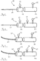
- the Figures 1 and 2 show an inventively designed instrument with the same distal part, but with different Proximal kind.
- the two instruments are in their entirety in the Figures 1 and 2 indicated by the reference numerals 10 and 20. They have straight instrument tips 11, 21, which each form the front portion of the distal part 12, 22.
- On the distal parts passive reflection markers 13, 23 are mounted, and in a middle distance from the instrument axis.
- the distal parts 12, 22 are connectable to proximal parts 14, 24, wherein the proximal part 14 in the FIG. 1 has only a single tracking marker 15.
- the characteristic configuration of the marker assembly would be in the case of the instrument FIG. 1 determined by the distance between the markers 13 and 15.
- At the instrument 20 after FIG. 2 becomes the characteristic arrangement determined by the relative distances between the three markers 23, 25 and 26 on the distal part 22 and the proximal part 24.
- FIGS. 3 and 4 another instrument according to the invention is shown which has a curved tip, designated 31 and 41, respectively.
- the instrument may in turn proximal parts 34 and 44, which with the Proximal kind 14 and 24 from the Figures 1 and 2 are identical.
- the instruments 30, 40 differ from the FIGS. 3 and 4 It can be seen that the markers 33, 43 have a greater distance from the instrument longitudinal axis and to the markers of the distal part than the markers 13, 23, and through This different measure differentiates the marker configurations altogether (markers on the proximal part plus markers on the distal part) from other marker configurations (eg for instruments 10 and 20). Because of these different marker configurations, a navigation system can then recognize that they are just the instruments 30 and 40, respectively, although the proximal parts 14 and 24 correspond to the proximal parts 34 and 44, respectively.
- FIGS. 5 and 6 and the instruments 50 and 60 shown there is corresponding, wherein the reference numerals with corresponding end numbers and corresponding parts as in the FIGS. 1 to 4 describe.
- the respective marker 53 or 63 only has a very short distance from the longitudinal axis of the instrument. Due to this short distance and the thus changed overall marker configuration for the instrument this in turn becomes clearly recognizable and identifiable.
- proximal part 14 it is possible to combine the proximal part 14 with one of the distal parts 11, 31, 51 and in each case to obtain another, uniquely identifiable instrument.
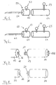
- FIG. 7 One way in which a distal part 12 can be connected to a proximal part 14 is in FIG FIG. 7 shown.
- the distal part 12 has a central threaded bore 16 and notch-like recesses on the outline of its end face.
- the proximal part 14 has a threaded rod 17 rotatable in it, which is connected to the attack 17A and is rotatable thereby.
- protruding tabs 19 are provided on the circumference.
- FIG. 8 shows for the embodiment according to FIG. 2 a further connection possibility in which the distal part 22 comprises a central bore 26, in which a latching extension 27 of the Proximalteils 24 can engage.
- the outwardly directed ribs 28 prevent rotation of the parts 22 and 24 against each other, and also a release of these two parts from each other. It could still be provided a device that folds away, for example, the ribs 28, so that the desired separation of the two parts can be done from each other in a simple manner.
- an alignment aid such as a mechanical engagement or a mark is provided so that the connection can go in the correct rotational position of the two parts to each other.
Landscapes
- Health & Medical Sciences (AREA)
- Surgery (AREA)
- Life Sciences & Earth Sciences (AREA)
- Heart & Thoracic Surgery (AREA)
- Pathology (AREA)
- Oral & Maxillofacial Surgery (AREA)
- Engineering & Computer Science (AREA)
- Biomedical Technology (AREA)
- Nuclear Medicine, Radiotherapy & Molecular Imaging (AREA)
- Medical Informatics (AREA)
- Molecular Biology (AREA)
- Animal Behavior & Ethology (AREA)
- General Health & Medical Sciences (AREA)
- Public Health (AREA)
- Veterinary Medicine (AREA)
- Surgical Instruments (AREA)
Claims (10)
- Instrument médical (10-60) avec une poignée et un segment fonctionnel (1-61), avec un agencement de repères de poursuite (13, 14, 15-63, 64, 65) sur l'instrument, caractérisé en ce que l'instrument est divisible en au moins deux parties et peut à nouveau être assemblé, au moins un repère de poursuite étant disposé sur chaque partie.
- Instrument médical (10-60) selon la revendication 1, caractérisé en ce qu'une première partie (12-62) de l'instrument (10-60) comprend le segment fonctionnel (1-61) et une seconde partie (14-64) de l'instrument (10-60) comprend au moins une partie de la poignée.
- Instrument médical (10-60) selon la revendication 2, caractérisé en ce que sur la première partie de l'instrument (10-60) est disposé au moins un repère de poursuite (13-63) ou un groupe de repères de poursuite, le repère de poursuite (13-63) ou le groupe de repères de poursuite étant clairement associé, dans leur forme ou leur disposition, au segment fonctionnel (11-61) de l'instrument (10-60).
- Instrument médical (10-60) selon la revendication 3, caractérisé en ce que l'association du repère de poursuite (13-63) ou du groupe de repères de poursuite est déterminée par une disposition caractéristique associée à la partie fonctionnelle, en particulier par une position axiale ou radiale sur la première partie d'instrument (12-62) par rapport à la géométrie de localisation de la seconde partie d'instrument (14-64).
- Instrument médical (10-60) selon l'une quelconque des revendications 1 à 4, caractérisé en ce que sur la première partie d'instrument (12-62) est disposé un repère de poursuite (13-63) et sur la seconde partie d'instrument (14-64) un repère de poursuite.
- Instrument médical (10-60) selon l'une quelconque des revendications 1 à 4, caractérisé en ce que sur la première partie d'instrument (12-62) est disposé un repère de poursuite (13-63) et sur la seconde partie d'instrument (14-64) un groupe de repères de poursuite avec deux repères de poursuite ou plus.
- Instrument médical (10-60) selon l'une quelconque des revendications 1 à 6, caractérisé en ce que les deux parties d'instrument (12-62 ; 14-64) peuvent être reliées par une liaison solidaire en rotation, la liaison comprenant en particulier un ou plusieurs des types de liaison suivants :- une liaison filetée (16, 17) avec des moyens de prise (18) par complémentarité de formes ou à friction entre la première et la seconde partie d'instrument (12-62 ; 14-64) ;- une liaison clipsée (26, 28) avec des moyens de prise (28) par complémentarité de formes ou à friction entre la première et la seconde partie d'instrument (12-62 ; 14-64) ;- une liaison à enfichage avec des moyens de prise (28) par complémentarité de formes ou à friction entre la première et la seconde partie d'instrument (12-62 ; 14-64).
- Instrument médical (10-60) selon l'une quelconque des revendications 1 à 7, caractérisé en ce que les repères de poursuite (13, 14, 15-63, 64, 65) servent à la localisation de l'instrument au moyen d'un système médical de poursuite et à l'identification automatique de l'instrument par un système médical de navigation.
- Jeu d'instruments médicaux avec au moins deux instruments selon l'une quelconque des revendications 1 à 8.
- Jeu d'instruments médicaux selon la revendication 8, dans lequel les instruments sont constitués à partir de différentes premières parties d'instrument, qui comprennent chacune le segment fonctionnel (11-61), et à partir de la même seconde partie d'instrument ou de secondes parties d'instrument identiques (14-64) qui comprennent au moins une partie de la poignée.
Priority Applications (3)
| Application Number | Priority Date | Filing Date | Title |
|---|---|---|---|
| DE502006002954T DE502006002954D1 (de) | 2006-08-22 | 2006-08-22 | Trackingfähiges medizinisches Instrument mit austauschbarer Spitze |
| EP06017395A EP1891908B1 (fr) | 2006-08-22 | 2006-08-22 | Instrument chirurgical repérable avec extrémité remplaçable |
| US11/842,969 US20080051768A1 (en) | 2006-08-22 | 2007-08-22 | Trackable medical instrument comprising an exchangeable tip |
Applications Claiming Priority (1)
| Application Number | Priority Date | Filing Date | Title |
|---|---|---|---|
| EP06017395A EP1891908B1 (fr) | 2006-08-22 | 2006-08-22 | Instrument chirurgical repérable avec extrémité remplaçable |
Publications (2)
| Publication Number | Publication Date |
|---|---|
| EP1891908A1 EP1891908A1 (fr) | 2008-02-27 |
| EP1891908B1 true EP1891908B1 (fr) | 2009-02-25 |
Family
ID=37635650
Family Applications (1)
| Application Number | Title | Priority Date | Filing Date |
|---|---|---|---|
| EP06017395A Not-in-force EP1891908B1 (fr) | 2006-08-22 | 2006-08-22 | Instrument chirurgical repérable avec extrémité remplaçable |
Country Status (3)
| Country | Link |
|---|---|
| US (1) | US20080051768A1 (fr) |
| EP (1) | EP1891908B1 (fr) |
| DE (1) | DE502006002954D1 (fr) |
Families Citing this family (10)
| Publication number | Priority date | Publication date | Assignee | Title |
|---|---|---|---|---|
| US11040458B2 (en) * | 2012-12-31 | 2021-06-22 | Matthew W. Krenik | Hair cutting device for automated hair cutting system |
| US10318024B2 (en) | 2016-10-14 | 2019-06-11 | Orthosoft, Inc. | Mechanical optical pointer |
| US11020187B2 (en) | 2017-09-21 | 2021-06-01 | Synaptive Medical Inc. | Tracked suction tool |
| EP3811888A1 (fr) | 2019-10-22 | 2021-04-28 | DePuy Ireland Unlimited Company | Procédé de démontage d'un réseau de marqueurs à partir d'une fixation de réseau et assemblage de réseau pour effectuer ledit procédé |
| US12016642B2 (en) * | 2021-09-08 | 2024-06-25 | Proprio, Inc. | Constellations for tracking instruments, such as surgical instruments, and associated systems and methods |
| WO2023220605A2 (fr) | 2022-05-09 | 2023-11-16 | Proprio, Inc. | Procédés et systèmes d'étalonnage d'instruments dans un système d'imagerie, tel qu'un système d'imagerie chirurgicale |
| USD1091816S1 (en) | 2023-04-19 | 2025-09-02 | Stryker European Operations Limited | Surgical instrument tracker |
| EP4480438B1 (fr) * | 2023-06-22 | 2025-12-31 | Stryker European Operations Limited | Technique de détermination d'une orientation angulaire entre une extrémité de travail non symétrique en rotation d'un outil et un dispositif de suivi d'outil |
| USD1117755S1 (en) | 2023-08-18 | 2026-03-10 | Mako Surgical Corp. | Surgical tracker |
| USD1120320S1 (en) | 2023-08-18 | 2026-03-24 | Mako Surgical Corp. | Surgical tracker |
Family Cites Families (11)
| Publication number | Priority date | Publication date | Assignee | Title |
|---|---|---|---|---|
| US5617857A (en) * | 1995-06-06 | 1997-04-08 | Image Guided Technologies, Inc. | Imaging system having interactive medical instruments and methods |
| US6351659B1 (en) * | 1995-09-28 | 2002-02-26 | Brainlab Med. Computersysteme Gmbh | Neuro-navigation system |
| DE19639615C5 (de) | 1996-09-26 | 2008-11-06 | Brainlab Ag | Reflektorenreferenzierungssystem für chirurgische und medizinische Instrumente |
| DE29600990U1 (de) * | 1996-01-20 | 1996-04-11 | Elekta Instrument GmbH, 79224 Umkirch | Vorrichtung für die bildgeführte Chirurgie |
| US6021343A (en) * | 1997-11-20 | 2000-02-01 | Surgical Navigation Technologies | Image guided awl/tap/screwdriver |
| US6556857B1 (en) * | 2000-10-24 | 2003-04-29 | Sdgi Holdings, Inc. | Rotation locking driver for image guided instruments |
| US6887245B2 (en) * | 2001-06-11 | 2005-05-03 | Ge Medical Systems Global Technology Company, Llc | Surgical drill for use with a computer assisted surgery system |
| US20050113659A1 (en) * | 2003-11-26 | 2005-05-26 | Albert Pothier | Device for data input for surgical navigation system |
| US9393039B2 (en) * | 2003-12-17 | 2016-07-19 | Brainlab Ag | Universal instrument or instrument set for computer guided surgery |
| DE502004001659D1 (de) * | 2003-12-17 | 2006-11-16 | Brainlab Ag | Universelles Instrument bzw. Instrumentensatz zur Navigation in der computergestützten Chirurgie |
| US7840256B2 (en) * | 2005-06-27 | 2010-11-23 | Biomet Manufacturing Corporation | Image guided tracking array and method |
-
2006
- 2006-08-22 EP EP06017395A patent/EP1891908B1/fr not_active Not-in-force
- 2006-08-22 DE DE502006002954T patent/DE502006002954D1/de active Active
-
2007
- 2007-08-22 US US11/842,969 patent/US20080051768A1/en not_active Abandoned
Also Published As
| Publication number | Publication date |
|---|---|
| DE502006002954D1 (de) | 2009-04-09 |
| EP1891908A1 (fr) | 2008-02-27 |
| US20080051768A1 (en) | 2008-02-28 |
Similar Documents
| Publication | Publication Date | Title |
|---|---|---|
| EP1952779B1 (fr) | Méthode et système d'identification des instruments médicaux | |
| DE19518388C2 (de) | Medizinisches Instrument mit einem abwinkelbaren distalen Endstück | |
| AT393616B (de) | Chirurgisches heftinstrument zur durchfuehrung von intraluminalen anastomosen | |
| EP0980676B1 (fr) | Dispositif chirurgical d'anastomose | |
| EP0575878B1 (fr) | Trousse pour l'anesthésie | |
| DE102007011568A1 (de) | Medizinische Klemme, insbesondere Wirbelsäulen-Klemme | |
| EP1891908B1 (fr) | Instrument chirurgical repérable avec extrémité remplaçable | |
| WO1998017191A1 (fr) | Support autobloquant se fixant en un point | |
| DE19901389B4 (de) | Endoskopisches Behandlungssystem | |
| EP2422753A1 (fr) | Instrumentation pour introduire par rotation un implant dans un espace intervertébral | |
| DE10216928B4 (de) | In ein Endoskop einsetzbares Einweginstrument | |
| EP1543789B1 (fr) | Instrument universel ou ensemble d' instruments pour la navigation en chirurgie assistée par ordinateur | |
| DE202014003736U1 (de) | Retraktionssystem | |
| EP1437978A1 (fr) | Dispositif d'adaptation destine, en particulier, a des instruments chirurgicaux tels que des dispositifs de pointage | |
| DE102018104966A1 (de) | Laryngo-Pharyngoskop-Retraktor-System | |
| EP2129311A1 (fr) | Manipulateur pour matériaux ronds, en particulier pour une broche de kirschner | |
| DE19754779C2 (de) | Chirurgisches Instrument | |
| WO2020002457A1 (fr) | Appareil dentaire destiné à examiner les espaces entre les dents | |
| DE69608975T2 (de) | Zwischenstück für dentales Handstück | |
| DE10032126B4 (de) | Instrument zum Einführen eines Verbindungsstabes in und durch zueinander ausgerichtete Querbohrungen in den Köpfen von zwei oder mehreren in die Wirbelsäule eingeschraubten Pedikelschrauben | |
| DE102016010548A1 (de) | Transporteur | |
| DE102022131155A1 (de) | Medizinisches instrument zum multidirektionalen verdüsen eines fluids in einen hohlraum eines körpers und werkzeug dafür | |
| AT9257U1 (de) | Handgriff eines medizinischen instruments | |
| DE102016103681A1 (de) | Positioniervorrichtung zum Fixieren einer polyaxialen Platte an einem Röhrenknochen | |
| DE202013100878U1 (de) | Arthroskopieschaft |
Legal Events
| Date | Code | Title | Description |
|---|---|---|---|
| PUAI | Public reference made under article 153(3) epc to a published international application that has entered the european phase |
Free format text: ORIGINAL CODE: 0009012 |
|
| 17P | Request for examination filed |
Effective date: 20060822 |
|
| AK | Designated contracting states |
Kind code of ref document: A1 Designated state(s): AT BE BG CH CY CZ DE DK EE ES FI FR GB GR HU IE IS IT LI LT LU LV MC NL PL PT RO SE SI SK TR |
|
| AX | Request for extension of the european patent |
Extension state: AL BA HR MK YU |
|
| GRAP | Despatch of communication of intention to grant a patent |
Free format text: ORIGINAL CODE: EPIDOSNIGR1 |
|
| GRAS | Grant fee paid |
Free format text: ORIGINAL CODE: EPIDOSNIGR3 |
|
| AKX | Designation fees paid |
Designated state(s): DE FR GB IT |
|
| GRAA | (expected) grant |
Free format text: ORIGINAL CODE: 0009210 |
|
| AK | Designated contracting states |
Kind code of ref document: B1 Designated state(s): DE FR GB IT |
|
| REG | Reference to a national code |
Ref country code: GB Ref legal event code: FG4D Free format text: NOT ENGLISH |
|
| REF | Corresponds to: |
Ref document number: 502006002954 Country of ref document: DE Date of ref document: 20090409 Kind code of ref document: P |
|
| PLBE | No opposition filed within time limit |
Free format text: ORIGINAL CODE: 0009261 |
|
| STAA | Information on the status of an ep patent application or granted ep patent |
Free format text: STATUS: NO OPPOSITION FILED WITHIN TIME LIMIT |
|
| 26N | No opposition filed |
Effective date: 20091126 |
|
| PG25 | Lapsed in a contracting state [announced via postgrant information from national office to epo] |
Ref country code: IT Free format text: LAPSE BECAUSE OF FAILURE TO SUBMIT A TRANSLATION OF THE DESCRIPTION OR TO PAY THE FEE WITHIN THE PRESCRIBED TIME-LIMIT Effective date: 20090225 |
|
| GBPC | Gb: european patent ceased through non-payment of renewal fee |
Effective date: 20100822 |
|
| PG25 | Lapsed in a contracting state [announced via postgrant information from national office to epo] |
Ref country code: GB Free format text: LAPSE BECAUSE OF NON-PAYMENT OF DUE FEES Effective date: 20100822 |
|
| REG | Reference to a national code |
Ref country code: DE Ref legal event code: R082 Ref document number: 502006002954 Country of ref document: DE Representative=s name: SCHWABE SANDMAIR MARX, DE |
|
| REG | Reference to a national code |
Ref country code: DE Ref legal event code: R081 Ref document number: 502006002954 Country of ref document: DE Owner name: BRAINLAB AG, DE Free format text: FORMER OWNER: BRAINLAB AG, 85622 FELDKIRCHEN, DE Effective date: 20131104 Ref country code: DE Ref legal event code: R082 Ref document number: 502006002954 Country of ref document: DE Representative=s name: SCHWABE SANDMAIR MARX, DE Effective date: 20131104 Ref country code: DE Ref legal event code: R082 Ref document number: 502006002954 Country of ref document: DE Representative=s name: SCHWABE SANDMAIR MARX PATENTANWAELTE RECHTSANW, DE Effective date: 20131104 |
|
| REG | Reference to a national code |
Ref country code: FR Ref legal event code: PLFP Year of fee payment: 10 |
|
| PGFP | Annual fee paid to national office [announced via postgrant information from national office to epo] |
Ref country code: DE Payment date: 20150821 Year of fee payment: 10 |
|
| PGFP | Annual fee paid to national office [announced via postgrant information from national office to epo] |
Ref country code: FR Payment date: 20150820 Year of fee payment: 10 |
|
| REG | Reference to a national code |
Ref country code: DE Ref legal event code: R082 Ref document number: 502006002954 Country of ref document: DE Representative=s name: SCHWABE SANDMAIR MARX PATENTANWAELTE RECHTSANW, DE Ref country code: DE Ref legal event code: R081 Ref document number: 502006002954 Country of ref document: DE Owner name: BRAINLAB AG, DE Free format text: FORMER OWNER: BRAINLAB AG, 85622 FELDKIRCHEN, DE Ref country code: DE Ref legal event code: R119 Ref document number: 502006002954 Country of ref document: DE |
|
| REG | Reference to a national code |
Ref country code: FR Ref legal event code: ST Effective date: 20170428 |
|
| PG25 | Lapsed in a contracting state [announced via postgrant information from national office to epo] |
Ref country code: DE Free format text: LAPSE BECAUSE OF NON-PAYMENT OF DUE FEES Effective date: 20170301 Ref country code: FR Free format text: LAPSE BECAUSE OF NON-PAYMENT OF DUE FEES Effective date: 20160831 |