EP1891723B1 - Procede pour determiner un type d'interconnexion d'au moins deux dispositifs electriques et systeme comportant plusieurs dispositifs electriques - Google Patents
Procede pour determiner un type d'interconnexion d'au moins deux dispositifs electriques et systeme comportant plusieurs dispositifs electriques Download PDFInfo
- Publication number
- EP1891723B1 EP1891723B1 EP06753314.1A EP06753314A EP1891723B1 EP 1891723 B1 EP1891723 B1 EP 1891723B1 EP 06753314 A EP06753314 A EP 06753314A EP 1891723 B1 EP1891723 B1 EP 1891723B1
- Authority
- EP
- European Patent Office
- Prior art keywords
- voltage
- devices
- terminal
- converter
- arrangements
- Prior art date
- Legal status (The legal status is an assumption and is not a legal conclusion. Google has not performed a legal analysis and makes no representation as to the accuracy of the status listed.)
- Active
Links
Images


Classifications
-
- H—ELECTRICITY
- H02—GENERATION; CONVERSION OR DISTRIBUTION OF ELECTRIC POWER
- H02J—CIRCUIT ARRANGEMENTS OR SYSTEMS FOR SUPPLYING OR DISTRIBUTING ELECTRIC POWER; SYSTEMS FOR STORING ELECTRIC ENERGY
- H02J1/00—Circuit arrangements for dc mains or dc distribution networks
- H02J1/10—Parallel operation of dc sources
- H02J1/102—Parallel operation of dc sources being switching converters
-
- G—PHYSICS
- G01—MEASURING; TESTING
- G01R—MEASURING ELECTRIC VARIABLES; MEASURING MAGNETIC VARIABLES
- G01R31/00—Arrangements for testing electric properties; Arrangements for locating electric faults; Arrangements for electrical testing characterised by what is being tested not provided for elsewhere
- G01R31/50—Testing of electric apparatus, lines, cables or components for short-circuits, continuity, leakage current or incorrect line connections
- G01R31/52—Testing for short-circuits, leakage current or ground faults
-
- G—PHYSICS
- G01—MEASURING; TESTING
- G01R—MEASURING ELECTRIC VARIABLES; MEASURING MAGNETIC VARIABLES
- G01R31/00—Arrangements for testing electric properties; Arrangements for locating electric faults; Arrangements for electrical testing characterised by what is being tested not provided for elsewhere
- G01R31/50—Testing of electric apparatus, lines, cables or components for short-circuits, continuity, leakage current or incorrect line connections
- G01R31/54—Testing for continuity
-
- H—ELECTRICITY
- H02—GENERATION; CONVERSION OR DISTRIBUTION OF ELECTRIC POWER
- H02J—CIRCUIT ARRANGEMENTS OR SYSTEMS FOR SUPPLYING OR DISTRIBUTING ELECTRIC POWER; SYSTEMS FOR STORING ELECTRIC ENERGY
- H02J7/00—Circuit arrangements for charging or depolarising batteries or for supplying loads from batteries
- H02J7/34—Parallel operation in networks using both storage and other dc sources, e.g. providing buffering
- H02J7/35—Parallel operation in networks using both storage and other dc sources, e.g. providing buffering with light sensitive cells
Definitions
- the invention relates to a method for determining an interconnection type of at least two electrical devices, each of which has a similar terminal arrangement. Furthermore, the invention relates to a system with a plurality of electrical devices, each having a similar terminal arrangement, and a control device.
- Solar cells are used to convert sunlight into electrical energy.
- Solar cells are often grouped into panels to produce higher voltage and power than could be provided by a single solar cell.
- Several panels are often connected in series to form a string.
- a typical photovoltaic system uses a solar cell string that provides varying electrical power. This power depends, for example, on the amount of sunlight (morning, noon, evening), shading and ambient temperature from. This power is converted by a DC-DC converter in a constant DC link voltage. An inverter stage then generates an AC voltage that can be used either directly, for example, in household appliances, or that can be fed into a higher-level network. This can be both a single-phase voltage and a multi-phase voltage.
- Such a configuration is, for example DE 101 36 147 A1 known.
- a DC-DC converter usually has two characteristics that are disadvantageous in some respects.
- the controller must now "know" what configuration the individual DC-DC converters are in the system.
- the control device may, for example, only switch off those DC converters whose solar cells are connected to another DC-DC converter.
- the information can be provided to the controller by manual input.
- a fitter can flip a switch or enter a parameter via a keyboard.
- there is a considerable risk of incorrect input in particular in larger photovoltaic systems, where several hundred solar cell strings are present.
- the invention has for its object to increase the reliability of commissioning and operation of a system with multiple electrical devices.
- This object is achieved in a method of the type mentioned above in that one changes a voltage at the terminal arrangement of a first device and determines the changed voltage as the first voltage that at least at the terminal arrangement of a second device determines a second voltage and that by reference a comparison of the voltages determines whether or not there is an electrical connection between the terminal arrangements of the devices.
- the voltage at the first device is changed by loading the first device.
- sources of renewable energy such as solar cells
- the voltage thus drops under load from an open circuit voltage to an operating voltage. If the terminal assemblies of two devices are connected together, then the load on both devices will affect so that the voltages on both devices will drop. On the other hand, if such a connection does not exist between the terminal assemblies, then the voltages will not change accordingly.
- the determination is repeated and uses as the first means in successive determinations another means.
- the determination can be repeated every time the system is put into operation, or whenever the system or system begins to feed electrical power into a higher-level network. This ensures that you can not overlook a change in the configuration that may have occurred during breaks. Such a change can also take place unintentionally. It may be advantageous if you do not always use the same device as the first device, but you can substitute so to speak.
- the terminal arrangement used is an input terminal arrangement, which is in each case connected to a power source.
- a power source In this way one uses the internal resistance of the energy source to effect the voltage change.
- a source of renewable energy as an energy source.
- a source is also referred to as a regenerative energy source or source of regenerative energy.
- the problem is particularly significant.
- an output terminal arrangement may be used as the terminal arrangement.
- the internal resistance of the electrical device is used to change the output voltage.
- the first device is not connected to another device, one uses a device other than the first device and tests it with respect to the remaining devices. This ensures that you can also detect different types of connection. In a system or plant, several devices may be connected in parallel, while other devices are operated in isolation. This can be reliably determined with the proposed procedure.
- the determinations are repeated and that another device is used as the first device until all but one device have been used as the first device. So you test all connections so to speak, to determine whether somewhere parallel connections exist, ie the terminal arrangements are connected or not.
- a plurality of devices having a similar behavior and their terminal arrangements are interconnected, used together as the first device.
- these devices are interconnected.
- a characteristic value is determined for an alternating voltage.
- the characteristic value is a value that does not change with the same frequency as the AC voltage, for example the RMS value, an average peak-to-peak voltage or a rectified mean value. Such a value can be determined relatively easily. He is a sufficiently meaningful size to carry out the above-mentioned provisions.
- the invention is achieved in a system of the type mentioned above in that a sensor is arranged on each terminal arrangement, which is connected to the control device, wherein the control means for changing the voltage at each terminal arrangement, a comparator to voltages at different Compare terminal arrangements with each other, and having a memory means in which it stores in dependence on the output signal of the comparator, whether or not connection arrangements of electrical devices are connected to each other.
- the control device thus carries out the method described above and "remembers" which electrical devices are connected to one another and which are not. It may well happen that there are several groups of interconnected electrical facilities gives. The control device then has the option of controlling the individual devices in each group in a manner that is favorable for optimum operation.
- the electrical devices are designed as DC converters.
- the controller may, when the DC-DC converters are connected to each other, switch off individual DC-DC converters if the input power is insufficient.
- the output terminal arrangements of the DC-DC converter are connected in parallel.
- the DC-DC converters thus have a common output voltage.
- the output terminal assemblies are connected to an inverter.
- the DC-DC converters feed a DC link from which the inverter draws the electrical power.
- the electrical devices are designed as inverters. Here is basically the same thing.
- the terminal assemblies are formed as input terminal assemblies, each connected to a source of renewable energy.
- this source may be solar cell strings, to wind turbines, to hydropower plants, to fuel cells or the like.
- Fig. 1 shows a schematic representation of a system 1 for converting solar energy into electrical energy.
- system and “attachment” are used interchangeably below.
- the system 1 has a string 2 with schematically represented solar cells 3. Usually, a plurality of solar cells 3 are arranged on a panel or panel. Several such panels then form the string 2 in series. At the output of the string 2, the solar cells 3 supply a DC voltage. The voltage varies in this case, for example, depending on the solar radiation, the shading, the ambient temperature or other influences.
- the string 2 is connected to a power converter 4, which may also be referred to as a power converter.
- the power converter 4 initially has a DC-DC converter 5.
- the DC-DC converter 5 converts the variable DC voltage supplied from the string 2 into a constant DC voltage and outputs it to a DC link 6.
- the intermediate circuit 6 is connected to an inverter 7, which converts the DC voltage from the intermediate circuit 6 into a single-phase or multi-phase AC voltage and outputs this to a network 8.
- each DC-DC converter 5 tolerates the power supplied by its associated string 2. If the delivered power exceeds an upper limit, this could lead to damage or even destruction of the DC-DC converter. On the other hand, most DC-DC converters 5 have poor efficiency at low power. They consume electrical power, although they give little or no output power.
- a control device 9 is required.
- the control device 9 controls, as indicated by dashed lines 10, the individual DC-DC converter 5 as needed.
- the parallel connection of the individual strings 2 makes it possible to distribute the electrical power delivered by the strings 2 to the DC-DC converters 5, so that overloading is not to be feared.
- the control device 9 can also simply switch off individual DC converters if the electrical power supplied by the strings 2 is too low. In this case, the power loss, which requires each DC converter 5, saved in the switched-off DC converters 5.
- the control device 9 can determine in which configuration the strings 2 are connected to the power converter 4, a sensor 12 is arranged at the input terminal arrangement 11 of each DC-DC converter 5, which is connected to the control device 9 via line sections 13 shown in phantom ,
- the line sections 10, 13 may have different configurations. It may be electrical lines or optical lines. It is also possible to form the corresponding paths between the control device 9, the DC-DC converters 5 and the sensors 12 without wires and then to effect the corresponding signal transmission via electromagnetic waves, light, sound or the like.
- the sensor 12 on the input terminal assembly 11 of the DC-DC converter 5 is formed here as a separate element. It is understood, however, that the control device 9 can experience the corresponding information directly in the DC-DC converter 5, for example via a voltage measurement at the input terminal arrangement 11.
- control device 9 can now determine in which configuration the strings 2 are connected to the power converter 4, it carries out at least after start-up, but preferably more often, for example after each power-free period or at regular intervals, an algorithm that is brief as to describe follows:
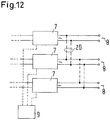
- the control device 9 selects a first DC-DC converter 5 and lowers the voltage there. This is preferably done by the control means controlling the DC-DC converter to supply electrical energy to the DC-link 6. Another remedy for this is schematically in Fig. 11 shown.
- the control device 9 actuates an electromagnet 14 which closes a switch 15. With the closing of the switch, a resistor 16 is connected in parallel with the input Anschlußanord- so that flows through the resistor 16, a current. Since the string 2 has an internal resistance, this leads to a decrease in the voltage at the input terminal assembly 11. At the input terminal assemblies 11 of the other DC-DC converter 5, however, no power is removed. The voltage at the input terminal assemblies 11 of the other DC-DC converters 5 is measured.
- the controller 9 detects this and then notes in a memory 17 shown only schematically that for the future, ie until the next review, the strings 2 are connected in parallel or not.
- the control device 9 selects a DC-DC converter 5 as a "master".
- the remaining DC converters 5 are treated as "slaves".
- the master is put into operation by taking power from its input.
- the slaves are placed in a state where such power extraction does not take place.
- the voltage of an open circuit voltage ie the open circuit voltage of the connected to the master string 2
- the power drawn at the input terminal arrangement 11 is increased until the input voltage at the master has dropped to a predetermined proportion of the open circuit voltage. After a predetermined time, the voltage difference between the master and each slave is calculated or otherwise determined.
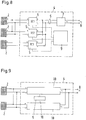
- a corresponding algorithm is shown schematically in Fig. 5 shown.
- a step 21 one waits as to whether at least two DC-DC converters 5 have reported themselves ready. This is the case, for example, if a sufficient DC voltage is present at its input terminal arrangement 11.
- decision 22 it is checked whether two DC-DC converters 5 have reported as ready. If this is not the case, you keep waiting. If you have two ready DC-DC converters 5, they are calibrated in a step 23. For this purpose, all DC converters 5 are switched off.
- the control device 9 records the measured voltage differences between the individual DC-DC converters 5. For example, it is possible to compensate for offsets which can occur in the measured voltages of each individual DC-DC converter 5.
- step 25 it is examined in a step 25 whether all the modules, that is to say all DC converters 5, have been tested. If only one DC-DC converter 5 has been untested, this DC-DC converter 5 is noted in the memory 17 as an "individual mode", ie the controller 9 has then found that this DC-DC converter 5 has been connected in parallel with no other DC-DC converter 5 in the input. If the decision 26 is affirmative, then in a step 27, all errors that may have occurred are output. Otherwise, the process is ended (step 28).
- step 29 If there are still untested DC-DC converters 5, the next DC-DC converter 5 is tested in a step 29. If this test has been interrupted (decision 30), one returns to step 25. In a decision 31 it is checked whether the test has been carried out to the end. If this is the case, in a step 32 for each DC-DC converter 5, the operating mode is set, ie individual operation or operation in parallel with other DC-DC converters 5.
- DC1 is turned on to provide power while DC2 and DC3 remain off.
- the controller 9 knows that DC1 is not connected in parallel with DC2 or DC3. That's why DC1 is allowed to continue generating energy.
- the memory device 9 notices that DC1 is arranged individually.
- DC2 is switched on and supplies energy.
- DC3 remains off.
- the controller 9 knows that DC2 and DC3 are not connected in parallel because no voltage change has occurred at the input of DC3.
- DC2 is allowed to continue to generate (i.e., deliver) energy in the individual mode of operation.
- DC3 Since DC3 is the last untested DC-DC converter 5, it can not be connected in parallel with any other DC-DC converter 5. For this reason, the controller 9 notices that DC3 is also operating in the individual mode of operation and DC3 may continue to generate power.
- generator energy is meant here that the DC-DC converter 5 feed the current from the strings 2 of the solar cell 3 in the intermediate circuit 3.
- Fig. 7 shows an example in which three strings 2 are connected in parallel.
- the procedure is as follows:
- the power converter 4 is connected to the network 8.
- the calibration is performed while all DC-DC converters 5 are turned off.
- the DC-DC converter DC1 is turned on, that is loaded at its input.
- the two DC-DC converters DC2 and DC3 remain switched off.
- the controller 9 knows that DC1 is in parallel with DC2 and DC3. All three DC converters 5 are thus noted as connected in parallel. Since no untested DC-DC converter 5 remains, the test is performed.
- Fig. 8 only two strings 2 are connected in parallel with each other.
- the third string is only connected to the DC-DC converter DC3.
- the missing connection may have been forgotten during assembly. It is also possible that it has been damaged by a storm or the like.
- the test is as follows: The power converter 4 is connected to the network 8. The calibration is performed while all DC-DC converters 5 are turned off.
- DC1 is turned on while DC2 and DC3 are off. After a predetermined time, the system will know that DC1 is in parallel with DC2. DC1 and DC2 are stored as connected in parallel. Since DC3 is the last untested DC-DC converter 5, it can not be connected in parallel with any other DC-DC converter 5. DC3 is then operated as an individual DC-DC converter. Since no untested DC-DC converter 5 remain, the test is performed.
- the voltage to which the input of the master is lowered depends on the characteristics of the power source, in the present case the strings 2.
- the sensitivity of the voltage measurement technique can also be play a role, the accuracy of the voltage measurement and similar factors. For example, if one uses a 3 kW converter operated with a solar cell string 2, then a voltage of 80% of the open circuit voltage is suitable.
- the predetermined time allowed to elapse to produce a stable state i. to check whether the voltages have evolved the same or different, depends on the transient properties of the system. For example, in the above example of a 3 kW converter, one may consider a period of 45 seconds to be sufficient for the stabilization of the voltage.
- control device 9 is connected to the DC-DC converters 5 via line sections in connections. They can be analog or digital, as a bus system or wirelessly. The signals of the sensors 12 can be transmitted accordingly.
- the controller 9 need not be physically separate from the DC-DC converters 5. It could for example be assembled with one of the transducers and from there control the remaining DC transducers 5 with the aid of the above-described line sections.
- the controller 9 may, in an advantageous embodiment, start each time with another DC-to-DC converter 5, i. DC1 for the first test, DC2 for the second test, DC3 for the third test and DC1 for the fourth test. This can be used to correct errors.
- the procedure also works when two or more DC-DC converters with their associated strings 2 of DC cells 3 operate as a master unit.
- the controller ensures that the load is distributed in a certain way to the DC-DC converter 5.
- control devices 9 can then work together to decide which DC-DC converter 5 should operate as a master and which as a slave.
- the approach may also be used when the power converter uses 4 units 18 which feed the power from the strings 2 directly into the grid 8, i. without a led out DC intermediate circuit. 6
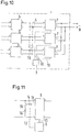
- the procedure can also be used in a system having a plurality of inverters 7, as in, for example, US Pat Fig. 10 is shown. With dashed lines 19 possible connections to the input parallel connection of the inverter 7 are shown here.
- the inputs described above are in this case the inputs of the inverters from the intermediate circuit 6.
- the control device 9 controls the inverters 7, ie switches them on or off as required to produce the required power states.
- the procedure described above can also be used if the outputs of the inverters 7 are connected in parallel. With dashed lines 20 possible connections are shown. One generates in this case a power at an output and measures whether the resulting Voltage at other outputs can be detected.
- the advantage of such a procedure is that one or more output stages, ie one or more inverters 7 can be switched off in order to save power when the input power is too low.
- the procedure works both with DC voltage and AC voltage. With AC voltage it is sufficient to determine the RMS value or another value which changes more slowly than with the frequency of the AC voltage, for example a peak voltage, if necessary averaged, an average of a rectified voltage or the like.
Claims (16)
- Procédé de détermination d'un mode d'interconnexion d'au moins deux dispositifs électriques, dont chacun possède un arrangement de raccordement identique, lequel est respectivement relié à une source d'énergie qui possède au moins une cellule solaire, caractérisé en ce qu'une tension au niveau de l'arrangement de raccordement d'un premier dispositif est modifiée en mettant en charge la source d'énergie reliée au premier dispositif avec le premier dispositif, et la modification de la tension est déterminée en tant que première variation de tension, et une deuxième variation de tension est déterminée au moins au niveau de l'arrangement de raccordement d'un deuxième dispositif en conséquence de la mise en charge et une comparaison des variations de tension servant à déterminer s'il existe ou non une liaison électrique entre les arrangements de raccordement des dispositifs.
- Procédé selon la revendication 1, la détermination étant répétée et un autre dispositif étant utilisé en tant que premier dispositif dans les déterminations successives.
- Procédé selon la revendication 1 ou 2, un arrangement de raccordement d'entrée étant utilisé comme arrangement de raccordement.
- Procédé selon l'une des revendications 1 à 3, l'un des deux dispositifs n'étant mis hors tension à faible puissance que s'il existe une liaison électrique entre les arrangements de raccordement des dispositifs.
- Procédé selon l'une des revendications 1 à 2, l'arrangement de raccordement utilisé étant un arrangement de raccordement de sortie.
- Procédé selon l'une des revendications 1 à 5, selon lequel, si une détermination amène à constater que le premier dispositif n'est pas relié électriquement à un autre dispositif, un autre dispositif est alors utilisé comme premier dispositif et celui-ci est alors testé en référence aux dispositifs restants.
- Procédé selon la revendication 6, les déterminations étant répétées et un autre dispositif étant utilisé comme premier dispositif jusqu'à ce que tous les dispositifs, sauf un, ont été utilisés en tant que premier dispositif.
- Procédé selon l'une des revendications 1 à 7, plusieurs dispositifs qui possèdent un comportement identique et dont les arrangements de raccordement sont reliés entre eux étant utilisés en commun en tant que premier dispositif.
- Procédé selon l'une des revendications 1 à 8, une valeur caractéristique étant déterminée en présence d'une tension alternative.
- Système comprenant plusieurs dispositifs électriques (5), dont chacun possède un arrangement de raccordement (11) identique, et un dispositif de commande (9), une chaîne de cellules solaires étant respectivement raccordée à chacun des arrangements de raccordement, caractérisé en ce qu'un capteur (12) est disposé au niveau de chaque arrangement de raccordement (11), lequel est relié au dispositif de commande (9), le dispositif de commande (9) possédant des moyens pour modifier la tension au niveau de chaque arrangement de raccordement (11) par mise en charge des cellules solaires, un comparateur pour comparer entre elles les variations de tension qui sont la conséquence de la mise en charge susmentionnée au niveau des différents arrangements de raccordement (11), et un dispositif de mémorisation (17) dans lequel il enregistre, en fonction du signal de sortie du comparateur, si les arrangements de raccordement (11) des dispositifs électriques (5) sont reliés entre eux ou non.
- Système selon la revendication 10, les dispositifs électriques (5) étant réalisés sous la forme de convertisseurs de tension continue.
- Système selon la revendication 11, les arrangements de raccordement de sortie des convertisseurs de tension continue (5) étant branchés en parallèle.
- Système selon la revendication 12, les arrangements de raccordement de sortie étant reliés à un onduleur (7).
- Système selon la revendication 10, les dispositifs électriques (5) étant réalisés sous la forme d'onduleurs.
- Système selon la revendication 14, les arrangements de raccordement de sortie des onduleurs étant branchés en parallèle.
- Système selon l'une des revendications 10 à 15, les arrangements de raccordement (11) étant réalisés sous la forme d'arrangements de raccordement d'entrée qui sont respectivement reliés à une source (2) d'énergie renouvelable.
Applications Claiming Priority (2)
| Application Number | Priority Date | Filing Date | Title |
|---|---|---|---|
| DE102005028513.9A DE102005028513B4 (de) | 2005-06-17 | 2005-06-17 | Verfahren zum Bestimmen einer Zusammenschaltungsart von mindestens zwei elektrischen Einrichtungen und System mit mehreren elektrischen Einrichtungen |
| PCT/DK2006/000347 WO2006133714A1 (fr) | 2005-06-17 | 2006-06-15 | Procede pour determiner un type d'interconnexion d'au moins deux dispositifs electriques et systeme comportant plusieurs dispositifs electriques |
Publications (2)
| Publication Number | Publication Date |
|---|---|
| EP1891723A1 EP1891723A1 (fr) | 2008-02-27 |
| EP1891723B1 true EP1891723B1 (fr) | 2018-11-21 |
Family
ID=37036768
Family Applications (1)
| Application Number | Title | Priority Date | Filing Date |
|---|---|---|---|
| EP06753314.1A Active EP1891723B1 (fr) | 2005-06-17 | 2006-06-15 | Procede pour determiner un type d'interconnexion d'au moins deux dispositifs electriques et systeme comportant plusieurs dispositifs electriques |
Country Status (6)
| Country | Link |
|---|---|
| US (2) | US7965088B2 (fr) |
| EP (1) | EP1891723B1 (fr) |
| KR (1) | KR100974176B1 (fr) |
| CN (1) | CN101253665B (fr) |
| DE (1) | DE102005028513B4 (fr) |
| WO (1) | WO2006133714A1 (fr) |
Families Citing this family (22)
| Publication number | Priority date | Publication date | Assignee | Title |
|---|---|---|---|---|
| WO2008149393A1 (fr) * | 2007-06-06 | 2008-12-11 | Power-One Italy S.P.A. | Alimentation en puissance électrique à l'aide d'une pluralité d'inverseurs parallèles et procédé de commande basé sur le suivi de point de puissance maximale |
| EP2232691B1 (fr) * | 2007-11-30 | 2019-03-27 | Alencon Acquisition Co., LLC | Systemes d'inverseurs de source de courant regules synchronises a grille multiphase |
| FR2940476B1 (fr) * | 2008-12-18 | 2011-02-25 | Total Sa | Systeme de gestion electronique de cellules photovoltaiques |
| ES2374462B1 (es) * | 2009-02-18 | 2012-09-27 | Montajes Y Proyectos Electrotécnicos, S.L. | Dispositivo de determinación de la tensión y corrientes entregadas por un panel fotovoltaico, instalación provista de un tal dispositivo y procedimiento de adaptación de la impedancia a partir de un tal dispositivo. |
| IT1394682B1 (it) * | 2009-07-10 | 2012-07-13 | Agostinelli | Apparato e metodo per l'alimentazione disaccoppiata di circuiti elettronici. |
| FR2953996B1 (fr) * | 2009-12-11 | 2012-01-20 | Centre Nat Rech Scient | Systeme de gestion electronique de cellules photovoltaiques fonction de la meteorologie |
| WO2012041317A2 (fr) * | 2010-09-27 | 2012-04-05 | Danfoss Solar Inverters A/S | Centrale électrique photovoltaïque |
| US9350166B2 (en) | 2010-10-05 | 2016-05-24 | Alencon Acquisition Co., Llc | High voltage energy harvesting and conversion renewable energy utility size electric power systems and visual monitoring and control systems for said systems |
| WO2012049670A1 (fr) * | 2010-10-12 | 2012-04-19 | Dsp Group Ltd. | Détection du type de connexion d'une broche |
| DE102010050785B4 (de) * | 2010-11-10 | 2015-02-12 | Sma Solar Technology Ag | Verfahren zur Verifizierung einer elektrischen Verbindung in einer Energieerzeugungsanlage |
| KR101104922B1 (ko) * | 2010-12-24 | 2012-01-12 | 한양전공주식회사 | 태양광 발전 설비 |
| EP2707933A4 (fr) | 2011-05-12 | 2015-05-20 | Alencon Acquisition Co Llc | Systèmes d'alimentation électrique de récolte d'énergie à haute tension et d'énergie renouvelable de conversion de la taille d'une installation et systèmes de surveillance et de contrôle visuels |
| CN102801179A (zh) * | 2011-05-26 | 2012-11-28 | 武汉金天新能源科技有限公司 | 一种光伏并网微逆变器系统 |
| JP5340357B2 (ja) | 2011-09-06 | 2013-11-13 | 三菱電機株式会社 | 電源システム |
| DE102012104560B4 (de) * | 2012-05-25 | 2016-05-25 | Sma Solar Technology Ag | Erkennung der Stringkonfiguration für einen Multistring-Wechselrichter |
| US20150084663A1 (en) * | 2012-06-12 | 2015-03-26 | Dow Global Technologies Llc | Method and apparatus for detecting discontinuitues in a solar array |
| DE102012113016B4 (de) | 2012-12-21 | 2015-02-12 | Sma Solar Technology Ag | Netzersatzanlage und Verfahren zum Trennen eines lokalen Energieverteilungsnetzes von einem übergeordneten Energieversorgungsnetz |
| EP2951903B1 (fr) | 2013-01-30 | 2018-03-14 | SMA Solar Technology AG | Procédé et onduleur pour distribuer la puissance par l'intermédiaire de plusieurs sources de courant continu connectées collectivement à une entrée de tension continue d'un convertisseur cc/ca |
| CN104038036B (zh) | 2014-06-30 | 2016-08-24 | 阳光电源股份有限公司 | 悬浮电压抑制方法、装置、逆变器控制系统及其逆变器 |
| US10483759B2 (en) | 2016-04-07 | 2019-11-19 | Alencon Acquisition Co., Llc | Integrated multi-mode large-scale electric power support system for an electrical grid |
| CN108254651B (zh) * | 2016-12-28 | 2020-09-18 | 致茂电子(苏州)有限公司 | 接线检查方法 |
| EP3509205B1 (fr) * | 2018-01-05 | 2021-11-17 | ABB Schweiz AG | Procédé permettant de détecter la configuration de canal d'entrée d'un inverseur multicanal |
Family Cites Families (11)
| Publication number | Priority date | Publication date | Assignee | Title |
|---|---|---|---|---|
| CA2151684A1 (fr) * | 1994-06-30 | 1995-12-31 | David L. Aldridge | Systeme de commutation d'alimentation et de detection des defaillances |
| US6253330B1 (en) * | 1999-02-17 | 2001-06-26 | Lucent Technologies Inc. | Redundant regulated power supply system with monitoring of the backup power supply |
| US6127621A (en) * | 1999-04-02 | 2000-10-03 | The Aerospace Corporation | Power sphere |
| US6157308A (en) * | 1999-06-10 | 2000-12-05 | Lucent Technologies Inc. | Detecting hidden faults in reliable power systems |
| US6215312B1 (en) * | 1999-11-09 | 2001-04-10 | Steven Hoenig | Method and apparatus for analyzing an AgZn battery |
| DE10136147B4 (de) | 2001-07-25 | 2004-11-04 | Kolm, Hendrik, Dipl.-Ing. | Photovoltaischer Wechselstromerzeuger |
| GB2389471B (en) * | 2002-06-06 | 2005-09-21 | Sun Microsystems Inc | Latent fault detection in redundant power supply systems |
| WO2005016715A2 (fr) * | 2003-08-14 | 2005-02-24 | Ina-Schaeffler Kg | Actionneur pour un frein de stationnement |
| US7688029B2 (en) * | 2005-11-08 | 2010-03-30 | Eveready Battery Company, Inc. | Portable battery powered appliance and method of operation |
| JP4589888B2 (ja) * | 2006-03-23 | 2010-12-01 | 株式会社ケーヒン | 電池電圧測定回路、およびバッテリecu |
| US8190385B2 (en) * | 2008-04-29 | 2012-05-29 | Halliburton Energy Services, Inc. | System and method for testing a solar panel |
-
2005
- 2005-06-17 DE DE102005028513.9A patent/DE102005028513B4/de not_active Expired - Fee Related
-
2006
- 2006-06-15 WO PCT/DK2006/000347 patent/WO2006133714A1/fr active Application Filing
- 2006-06-15 US US11/922,307 patent/US7965088B2/en active Active
- 2006-06-15 KR KR1020077029476A patent/KR100974176B1/ko active IP Right Grant
- 2006-06-15 EP EP06753314.1A patent/EP1891723B1/fr active Active
- 2006-06-15 CN CN200680029789.7A patent/CN101253665B/zh active Active
-
2011
- 2011-05-04 US US13/100,382 patent/US20110204878A1/en not_active Abandoned
Non-Patent Citations (1)
| Title |
|---|
| None * |
Also Published As
| Publication number | Publication date |
|---|---|
| WO2006133714A1 (fr) | 2006-12-21 |
| DE102005028513A1 (de) | 2006-12-28 |
| CN101253665A (zh) | 2008-08-27 |
| US20110204878A1 (en) | 2011-08-25 |
| US20090237071A1 (en) | 2009-09-24 |
| DE102005028513B4 (de) | 2020-01-16 |
| US7965088B2 (en) | 2011-06-21 |
| KR100974176B1 (ko) | 2010-08-05 |
| CN101253665B (zh) | 2014-05-07 |
| KR20080036167A (ko) | 2008-04-25 |
| EP1891723A1 (fr) | 2008-02-27 |
Similar Documents
| Publication | Publication Date | Title |
|---|---|---|
| EP1891723B1 (fr) | Procede pour determiner un type d'interconnexion d'au moins deux dispositifs electriques et systeme comportant plusieurs dispositifs electriques | |
| DE10107600C1 (de) | Verfahren zum Betreiben eines photovoltaischen Solarmoduls und photovoltaischer Solarmodul | |
| AT501422B1 (de) | Wechselrichtersystem zum einspeisen in ein 3-phasennetz sowie wechselrichteranlage für ein 3-phasennetz | |
| EP2956572B1 (fr) | Empilement d'électrolyse et électrolyseur | |
| DE4032569A1 (de) | Netzgekoppelte photovoltaikanlage | |
| EP2179451A1 (fr) | Dispositif de commutation régulable pour module solaire | |
| DE102012106466A1 (de) | Steuerung von Betriebsmitteln über Beeinflussung der Netzspannung | |
| EP2369356A2 (fr) | Procédé et dispositif destinés à trouver des modules PV à puissance faible dans une installation photovoltaïque en utilisant de sectionneurs | |
| EP1970964A2 (fr) | Module solaire | |
| EP2044451B1 (fr) | Installation photovoltaïque | |
| DE102014210010A1 (de) | Verfahren und Vorrichtung zum Betrieb eines elektrischen Energiespeichersystems | |
| WO2020052936A1 (fr) | Parc éolien doté d'une unité de flux de puissance et unité de flux de puissance de ce type | |
| WO2021099085A1 (fr) | Procédé de détermination d'un paramètre de fonctionnement d'une installation pv, installation pv dotée d'un onduleur et onduleur pour une telle installation pv | |
| DE102013112988B4 (de) | Verfahren zum Betreiben eines DC/DC-Wandlers, über den ein Photovoltaikmodul mit anderen, eine andere Kennlinie aufweisenden Photovoltaikmodulen in Reihe geschaltet ist, sowie entsprechender DC/DC-Wandler und Photovoltaikgenerator | |
| DE102011121197B4 (de) | Verfahren zur Inbetriebnahme eines Wechselrichters und Wechselrichter | |
| WO2018054835A1 (fr) | Module solaire, installation photovoltaïque et procédé de limitation de tension | |
| WO2011054649A2 (fr) | Procédé et agencement pour le contrôle d'un module photovoltaïque | |
| DE102010007484A1 (de) | Steuerung für Fotovoltaik-Anlagen | |
| EP2355170A2 (fr) | Commande pour installations photovoltaïques | |
| DE102009042084A1 (de) | Wartungsarmes elektronisches Bauelement zur Verhinderung von Rückströmen bei gleichzeitigem Schutz vor Überströmen in Photovoltaikanlagen | |
| EP2933895A1 (fr) | Procédé de réglage et système doté d'un onduleur, d'une source de courant continu et d'une autre source de courant continu ou d'un écoulement de courant continu | |
| WO2015091848A1 (fr) | Unité de régulation de tension électrique | |
| DE10126303A1 (de) | Verfahren und System zur Betriebsverifikation | |
| DE10247776A1 (de) | Verfahren und Vorrichtung zur Diagnose von Photovoltaikgeneratoren | |
| EP2523339A2 (fr) | Procédé de génération d'énergie au moyen d'une installation photovoltaïque, notamment pour une compensation d'énergie entre les générateurs photovoltaïques et l'onduleur |
Legal Events
| Date | Code | Title | Description |
|---|---|---|---|
| PUAI | Public reference made under article 153(3) epc to a published international application that has entered the european phase |
Free format text: ORIGINAL CODE: 0009012 |
|
| 17P | Request for examination filed |
Effective date: 20071213 |
|
| AK | Designated contracting states |
Kind code of ref document: A1 Designated state(s): AT BE BG CH CY CZ DE DK EE ES FI FR GB GR HU IE IS IT LI LT LU LV MC NL PL PT RO SE SI SK TR |
|
| DAX | Request for extension of the european patent (deleted) | ||
| RIN1 | Information on inventor provided before grant (corrected) |
Inventor name: THORNGREEN, THOMAS, KURE Inventor name: BORUP, UFFE Inventor name: DOROFTE, CHRISTINEL |
|
| DAX | Request for extension of the european patent (deleted) | ||
| RAP1 | Party data changed (applicant data changed or rights of an application transferred) |
Owner name: DANFOSS POWER ELECTRONICS A/S |
|
| 17Q | First examination report despatched |
Effective date: 20141208 |
|
| RAP1 | Party data changed (applicant data changed or rights of an application transferred) |
Owner name: SMA SOLAR TECHNOLOGY AG |
|
| GRAP | Despatch of communication of intention to grant a patent |
Free format text: ORIGINAL CODE: EPIDOSNIGR1 |
|
| STAA | Information on the status of an ep patent application or granted ep patent |
Free format text: STATUS: GRANT OF PATENT IS INTENDED |
|
| RIC1 | Information provided on ipc code assigned before grant |
Ipc: H02J 1/10 20060101AFI20180604BHEP Ipc: G01R 31/02 20060101ALI20180604BHEP |
|
| INTG | Intention to grant announced |
Effective date: 20180710 |
|
| GRAS | Grant fee paid |
Free format text: ORIGINAL CODE: EPIDOSNIGR3 |
|
| GRAA | (expected) grant |
Free format text: ORIGINAL CODE: 0009210 |
|
| STAA | Information on the status of an ep patent application or granted ep patent |
Free format text: STATUS: THE PATENT HAS BEEN GRANTED |
|
| AK | Designated contracting states |
Kind code of ref document: B1 Designated state(s): AT BE BG CH CY CZ DE DK EE ES FI FR GB GR HU IE IS IT LI LT LU LV MC NL PL PT RO SE SI SK TR |
|
| REG | Reference to a national code |
Ref country code: CH Ref legal event code: EP |
|
| REG | Reference to a national code |
Ref country code: IE Ref legal event code: FG4D Free format text: LANGUAGE OF EP DOCUMENT: GERMAN |
|
| REG | Reference to a national code |
Ref country code: DE Ref legal event code: R096 Ref document number: 502006016112 Country of ref document: DE |
|
| REG | Reference to a national code |
Ref country code: AT Ref legal event code: REF Ref document number: 1068661 Country of ref document: AT Kind code of ref document: T Effective date: 20181215 |
|
| REG | Reference to a national code |
Ref country code: NL Ref legal event code: FP |
|
| PG25 | Lapsed in a contracting state [announced via postgrant information from national office to epo] |
Ref country code: LV Free format text: LAPSE BECAUSE OF FAILURE TO SUBMIT A TRANSLATION OF THE DESCRIPTION OR TO PAY THE FEE WITHIN THE PRESCRIBED TIME-LIMIT Effective date: 20181121 Ref country code: BG Free format text: LAPSE BECAUSE OF FAILURE TO SUBMIT A TRANSLATION OF THE DESCRIPTION OR TO PAY THE FEE WITHIN THE PRESCRIBED TIME-LIMIT Effective date: 20190221 Ref country code: LT Free format text: LAPSE BECAUSE OF FAILURE TO SUBMIT A TRANSLATION OF THE DESCRIPTION OR TO PAY THE FEE WITHIN THE PRESCRIBED TIME-LIMIT Effective date: 20181121 Ref country code: ES Free format text: LAPSE BECAUSE OF FAILURE TO SUBMIT A TRANSLATION OF THE DESCRIPTION OR TO PAY THE FEE WITHIN THE PRESCRIBED TIME-LIMIT Effective date: 20181121 Ref country code: IS Free format text: LAPSE BECAUSE OF FAILURE TO SUBMIT A TRANSLATION OF THE DESCRIPTION OR TO PAY THE FEE WITHIN THE PRESCRIBED TIME-LIMIT Effective date: 20190321 Ref country code: FI Free format text: LAPSE BECAUSE OF FAILURE TO SUBMIT A TRANSLATION OF THE DESCRIPTION OR TO PAY THE FEE WITHIN THE PRESCRIBED TIME-LIMIT Effective date: 20181121 |
|
| PG25 | Lapsed in a contracting state [announced via postgrant information from national office to epo] |
Ref country code: GR Free format text: LAPSE BECAUSE OF FAILURE TO SUBMIT A TRANSLATION OF THE DESCRIPTION OR TO PAY THE FEE WITHIN THE PRESCRIBED TIME-LIMIT Effective date: 20190222 Ref country code: PT Free format text: LAPSE BECAUSE OF FAILURE TO SUBMIT A TRANSLATION OF THE DESCRIPTION OR TO PAY THE FEE WITHIN THE PRESCRIBED TIME-LIMIT Effective date: 20190321 Ref country code: SE Free format text: LAPSE BECAUSE OF FAILURE TO SUBMIT A TRANSLATION OF THE DESCRIPTION OR TO PAY THE FEE WITHIN THE PRESCRIBED TIME-LIMIT Effective date: 20181121 |
|
| PG25 | Lapsed in a contracting state [announced via postgrant information from national office to epo] |
Ref country code: DK Free format text: LAPSE BECAUSE OF FAILURE TO SUBMIT A TRANSLATION OF THE DESCRIPTION OR TO PAY THE FEE WITHIN THE PRESCRIBED TIME-LIMIT Effective date: 20181121 Ref country code: CZ Free format text: LAPSE BECAUSE OF FAILURE TO SUBMIT A TRANSLATION OF THE DESCRIPTION OR TO PAY THE FEE WITHIN THE PRESCRIBED TIME-LIMIT Effective date: 20181121 Ref country code: PL Free format text: LAPSE BECAUSE OF FAILURE TO SUBMIT A TRANSLATION OF THE DESCRIPTION OR TO PAY THE FEE WITHIN THE PRESCRIBED TIME-LIMIT Effective date: 20181121 |
|
| REG | Reference to a national code |
Ref country code: DE Ref legal event code: R097 Ref document number: 502006016112 Country of ref document: DE |
|
| PG25 | Lapsed in a contracting state [announced via postgrant information from national office to epo] |
Ref country code: RO Free format text: LAPSE BECAUSE OF FAILURE TO SUBMIT A TRANSLATION OF THE DESCRIPTION OR TO PAY THE FEE WITHIN THE PRESCRIBED TIME-LIMIT Effective date: 20181121 Ref country code: SK Free format text: LAPSE BECAUSE OF FAILURE TO SUBMIT A TRANSLATION OF THE DESCRIPTION OR TO PAY THE FEE WITHIN THE PRESCRIBED TIME-LIMIT Effective date: 20181121 Ref country code: EE Free format text: LAPSE BECAUSE OF FAILURE TO SUBMIT A TRANSLATION OF THE DESCRIPTION OR TO PAY THE FEE WITHIN THE PRESCRIBED TIME-LIMIT Effective date: 20181121 |
|
| PLBE | No opposition filed within time limit |
Free format text: ORIGINAL CODE: 0009261 |
|
| STAA | Information on the status of an ep patent application or granted ep patent |
Free format text: STATUS: NO OPPOSITION FILED WITHIN TIME LIMIT |
|
| 26N | No opposition filed |
Effective date: 20190822 |
|
| PG25 | Lapsed in a contracting state [announced via postgrant information from national office to epo] |
Ref country code: SI Free format text: LAPSE BECAUSE OF FAILURE TO SUBMIT A TRANSLATION OF THE DESCRIPTION OR TO PAY THE FEE WITHIN THE PRESCRIBED TIME-LIMIT Effective date: 20181121 |
|
| PG25 | Lapsed in a contracting state [announced via postgrant information from national office to epo] |
Ref country code: MC Free format text: LAPSE BECAUSE OF FAILURE TO SUBMIT A TRANSLATION OF THE DESCRIPTION OR TO PAY THE FEE WITHIN THE PRESCRIBED TIME-LIMIT Effective date: 20181121 |
|
| REG | Reference to a national code |
Ref country code: CH Ref legal event code: PL |
|
| PG25 | Lapsed in a contracting state [announced via postgrant information from national office to epo] |
Ref country code: TR Free format text: LAPSE BECAUSE OF FAILURE TO SUBMIT A TRANSLATION OF THE DESCRIPTION OR TO PAY THE FEE WITHIN THE PRESCRIBED TIME-LIMIT Effective date: 20181121 |
|
| PG25 | Lapsed in a contracting state [announced via postgrant information from national office to epo] |
Ref country code: IE Free format text: LAPSE BECAUSE OF NON-PAYMENT OF DUE FEES Effective date: 20190615 |
|
| PG25 | Lapsed in a contracting state [announced via postgrant information from national office to epo] |
Ref country code: LU Free format text: LAPSE BECAUSE OF NON-PAYMENT OF DUE FEES Effective date: 20190615 Ref country code: CH Free format text: LAPSE BECAUSE OF NON-PAYMENT OF DUE FEES Effective date: 20190630 Ref country code: LI Free format text: LAPSE BECAUSE OF NON-PAYMENT OF DUE FEES Effective date: 20190630 |
|
| REG | Reference to a national code |
Ref country code: AT Ref legal event code: MM01 Ref document number: 1068661 Country of ref document: AT Kind code of ref document: T Effective date: 20190615 |
|
| PG25 | Lapsed in a contracting state [announced via postgrant information from national office to epo] |
Ref country code: AT Free format text: LAPSE BECAUSE OF NON-PAYMENT OF DUE FEES Effective date: 20190615 |
|
| PG25 | Lapsed in a contracting state [announced via postgrant information from national office to epo] |
Ref country code: CY Free format text: LAPSE BECAUSE OF FAILURE TO SUBMIT A TRANSLATION OF THE DESCRIPTION OR TO PAY THE FEE WITHIN THE PRESCRIBED TIME-LIMIT Effective date: 20181121 |
|
| PG25 | Lapsed in a contracting state [announced via postgrant information from national office to epo] |
Ref country code: HU Free format text: LAPSE BECAUSE OF FAILURE TO SUBMIT A TRANSLATION OF THE DESCRIPTION OR TO PAY THE FEE WITHIN THE PRESCRIBED TIME-LIMIT; INVALID AB INITIO Effective date: 20060615 |
|
| PGFP | Annual fee paid to national office [announced via postgrant information from national office to epo] |
Ref country code: NL Payment date: 20230620 Year of fee payment: 18 Ref country code: FR Payment date: 20230621 Year of fee payment: 18 Ref country code: DE Payment date: 20230620 Year of fee payment: 18 |
|
| PGFP | Annual fee paid to national office [announced via postgrant information from national office to epo] |
Ref country code: BE Payment date: 20230619 Year of fee payment: 18 |
|
| PGFP | Annual fee paid to national office [announced via postgrant information from national office to epo] |
Ref country code: IT Payment date: 20230630 Year of fee payment: 18 Ref country code: GB Payment date: 20230622 Year of fee payment: 18 |