EP1891723B1 - Method for determining the type of connection of at least two electrical devices and system comprising several electric devices - Google Patents
Method for determining the type of connection of at least two electrical devices and system comprising several electric devices Download PDFInfo
- Publication number
- EP1891723B1 EP1891723B1 EP06753314.1A EP06753314A EP1891723B1 EP 1891723 B1 EP1891723 B1 EP 1891723B1 EP 06753314 A EP06753314 A EP 06753314A EP 1891723 B1 EP1891723 B1 EP 1891723B1
- Authority
- EP
- European Patent Office
- Prior art keywords
- voltage
- devices
- terminal
- converter
- arrangements
- Prior art date
- Legal status (The legal status is an assumption and is not a legal conclusion. Google has not performed a legal analysis and makes no representation as to the accuracy of the status listed.)
- Active
Links
Images


Classifications
-
- H—ELECTRICITY
- H02—GENERATION; CONVERSION OR DISTRIBUTION OF ELECTRIC POWER
- H02J—CIRCUIT ARRANGEMENTS OR SYSTEMS FOR SUPPLYING OR DISTRIBUTING ELECTRIC POWER; SYSTEMS FOR STORING ELECTRIC ENERGY
- H02J1/00—Circuit arrangements for dc mains or dc distribution networks
- H02J1/10—Parallel operation of dc sources
- H02J1/102—Parallel operation of dc sources being switching converters
-
- G—PHYSICS
- G01—MEASURING; TESTING
- G01R—MEASURING ELECTRIC VARIABLES; MEASURING MAGNETIC VARIABLES
- G01R31/00—Arrangements for testing electric properties; Arrangements for locating electric faults; Arrangements for electrical testing characterised by what is being tested not provided for elsewhere
- G01R31/50—Testing of electric apparatus, lines, cables or components for short-circuits, continuity, leakage current or incorrect line connections
- G01R31/52—Testing for short-circuits, leakage current or ground faults
-
- G—PHYSICS
- G01—MEASURING; TESTING
- G01R—MEASURING ELECTRIC VARIABLES; MEASURING MAGNETIC VARIABLES
- G01R31/00—Arrangements for testing electric properties; Arrangements for locating electric faults; Arrangements for electrical testing characterised by what is being tested not provided for elsewhere
- G01R31/50—Testing of electric apparatus, lines, cables or components for short-circuits, continuity, leakage current or incorrect line connections
- G01R31/54—Testing for continuity
-
- H—ELECTRICITY
- H02—GENERATION; CONVERSION OR DISTRIBUTION OF ELECTRIC POWER
- H02J—CIRCUIT ARRANGEMENTS OR SYSTEMS FOR SUPPLYING OR DISTRIBUTING ELECTRIC POWER; SYSTEMS FOR STORING ELECTRIC ENERGY
- H02J7/00—Circuit arrangements for charging or depolarising batteries or for supplying loads from batteries
- H02J7/34—Parallel operation in networks using both storage and other dc sources, e.g. providing buffering
- H02J7/35—Parallel operation in networks using both storage and other dc sources, e.g. providing buffering with light sensitive cells
Definitions
- the invention relates to a method for determining an interconnection type of at least two electrical devices, each of which has a similar terminal arrangement. Furthermore, the invention relates to a system with a plurality of electrical devices, each having a similar terminal arrangement, and a control device.
- Solar cells are used to convert sunlight into electrical energy.
- Solar cells are often grouped into panels to produce higher voltage and power than could be provided by a single solar cell.
- Several panels are often connected in series to form a string.
- a typical photovoltaic system uses a solar cell string that provides varying electrical power. This power depends, for example, on the amount of sunlight (morning, noon, evening), shading and ambient temperature from. This power is converted by a DC-DC converter in a constant DC link voltage. An inverter stage then generates an AC voltage that can be used either directly, for example, in household appliances, or that can be fed into a higher-level network. This can be both a single-phase voltage and a multi-phase voltage.
- Such a configuration is, for example DE 101 36 147 A1 known.
- a DC-DC converter usually has two characteristics that are disadvantageous in some respects.
- the controller must now "know" what configuration the individual DC-DC converters are in the system.
- the control device may, for example, only switch off those DC converters whose solar cells are connected to another DC-DC converter.
- the information can be provided to the controller by manual input.
- a fitter can flip a switch or enter a parameter via a keyboard.
- there is a considerable risk of incorrect input in particular in larger photovoltaic systems, where several hundred solar cell strings are present.
- the invention has for its object to increase the reliability of commissioning and operation of a system with multiple electrical devices.
- This object is achieved in a method of the type mentioned above in that one changes a voltage at the terminal arrangement of a first device and determines the changed voltage as the first voltage that at least at the terminal arrangement of a second device determines a second voltage and that by reference a comparison of the voltages determines whether or not there is an electrical connection between the terminal arrangements of the devices.
- the voltage at the first device is changed by loading the first device.
- sources of renewable energy such as solar cells
- the voltage thus drops under load from an open circuit voltage to an operating voltage. If the terminal assemblies of two devices are connected together, then the load on both devices will affect so that the voltages on both devices will drop. On the other hand, if such a connection does not exist between the terminal assemblies, then the voltages will not change accordingly.
- the determination is repeated and uses as the first means in successive determinations another means.
- the determination can be repeated every time the system is put into operation, or whenever the system or system begins to feed electrical power into a higher-level network. This ensures that you can not overlook a change in the configuration that may have occurred during breaks. Such a change can also take place unintentionally. It may be advantageous if you do not always use the same device as the first device, but you can substitute so to speak.
- the terminal arrangement used is an input terminal arrangement, which is in each case connected to a power source.
- a power source In this way one uses the internal resistance of the energy source to effect the voltage change.
- a source of renewable energy as an energy source.
- a source is also referred to as a regenerative energy source or source of regenerative energy.
- the problem is particularly significant.
- an output terminal arrangement may be used as the terminal arrangement.
- the internal resistance of the electrical device is used to change the output voltage.
- the first device is not connected to another device, one uses a device other than the first device and tests it with respect to the remaining devices. This ensures that you can also detect different types of connection. In a system or plant, several devices may be connected in parallel, while other devices are operated in isolation. This can be reliably determined with the proposed procedure.
- the determinations are repeated and that another device is used as the first device until all but one device have been used as the first device. So you test all connections so to speak, to determine whether somewhere parallel connections exist, ie the terminal arrangements are connected or not.
- a plurality of devices having a similar behavior and their terminal arrangements are interconnected, used together as the first device.
- these devices are interconnected.
- a characteristic value is determined for an alternating voltage.
- the characteristic value is a value that does not change with the same frequency as the AC voltage, for example the RMS value, an average peak-to-peak voltage or a rectified mean value. Such a value can be determined relatively easily. He is a sufficiently meaningful size to carry out the above-mentioned provisions.
- the invention is achieved in a system of the type mentioned above in that a sensor is arranged on each terminal arrangement, which is connected to the control device, wherein the control means for changing the voltage at each terminal arrangement, a comparator to voltages at different Compare terminal arrangements with each other, and having a memory means in which it stores in dependence on the output signal of the comparator, whether or not connection arrangements of electrical devices are connected to each other.
- the control device thus carries out the method described above and "remembers" which electrical devices are connected to one another and which are not. It may well happen that there are several groups of interconnected electrical facilities gives. The control device then has the option of controlling the individual devices in each group in a manner that is favorable for optimum operation.
- the electrical devices are designed as DC converters.
- the controller may, when the DC-DC converters are connected to each other, switch off individual DC-DC converters if the input power is insufficient.
- the output terminal arrangements of the DC-DC converter are connected in parallel.
- the DC-DC converters thus have a common output voltage.
- the output terminal assemblies are connected to an inverter.
- the DC-DC converters feed a DC link from which the inverter draws the electrical power.
- the electrical devices are designed as inverters. Here is basically the same thing.
- the terminal assemblies are formed as input terminal assemblies, each connected to a source of renewable energy.
- this source may be solar cell strings, to wind turbines, to hydropower plants, to fuel cells or the like.
- Fig. 1 shows a schematic representation of a system 1 for converting solar energy into electrical energy.
- system and “attachment” are used interchangeably below.
- the system 1 has a string 2 with schematically represented solar cells 3. Usually, a plurality of solar cells 3 are arranged on a panel or panel. Several such panels then form the string 2 in series. At the output of the string 2, the solar cells 3 supply a DC voltage. The voltage varies in this case, for example, depending on the solar radiation, the shading, the ambient temperature or other influences.
- the string 2 is connected to a power converter 4, which may also be referred to as a power converter.
- the power converter 4 initially has a DC-DC converter 5.
- the DC-DC converter 5 converts the variable DC voltage supplied from the string 2 into a constant DC voltage and outputs it to a DC link 6.
- the intermediate circuit 6 is connected to an inverter 7, which converts the DC voltage from the intermediate circuit 6 into a single-phase or multi-phase AC voltage and outputs this to a network 8.
- each DC-DC converter 5 tolerates the power supplied by its associated string 2. If the delivered power exceeds an upper limit, this could lead to damage or even destruction of the DC-DC converter. On the other hand, most DC-DC converters 5 have poor efficiency at low power. They consume electrical power, although they give little or no output power.
- a control device 9 is required.
- the control device 9 controls, as indicated by dashed lines 10, the individual DC-DC converter 5 as needed.
- the parallel connection of the individual strings 2 makes it possible to distribute the electrical power delivered by the strings 2 to the DC-DC converters 5, so that overloading is not to be feared.
- the control device 9 can also simply switch off individual DC converters if the electrical power supplied by the strings 2 is too low. In this case, the power loss, which requires each DC converter 5, saved in the switched-off DC converters 5.
- the control device 9 can determine in which configuration the strings 2 are connected to the power converter 4, a sensor 12 is arranged at the input terminal arrangement 11 of each DC-DC converter 5, which is connected to the control device 9 via line sections 13 shown in phantom ,
- the line sections 10, 13 may have different configurations. It may be electrical lines or optical lines. It is also possible to form the corresponding paths between the control device 9, the DC-DC converters 5 and the sensors 12 without wires and then to effect the corresponding signal transmission via electromagnetic waves, light, sound or the like.
- the sensor 12 on the input terminal assembly 11 of the DC-DC converter 5 is formed here as a separate element. It is understood, however, that the control device 9 can experience the corresponding information directly in the DC-DC converter 5, for example via a voltage measurement at the input terminal arrangement 11.
- control device 9 can now determine in which configuration the strings 2 are connected to the power converter 4, it carries out at least after start-up, but preferably more often, for example after each power-free period or at regular intervals, an algorithm that is brief as to describe follows:
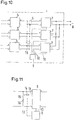
- the control device 9 selects a first DC-DC converter 5 and lowers the voltage there. This is preferably done by the control means controlling the DC-DC converter to supply electrical energy to the DC-link 6. Another remedy for this is schematically in Fig. 11 shown.
- the control device 9 actuates an electromagnet 14 which closes a switch 15. With the closing of the switch, a resistor 16 is connected in parallel with the input Anschlußanord- so that flows through the resistor 16, a current. Since the string 2 has an internal resistance, this leads to a decrease in the voltage at the input terminal assembly 11. At the input terminal assemblies 11 of the other DC-DC converter 5, however, no power is removed. The voltage at the input terminal assemblies 11 of the other DC-DC converters 5 is measured.
- the controller 9 detects this and then notes in a memory 17 shown only schematically that for the future, ie until the next review, the strings 2 are connected in parallel or not.
- the control device 9 selects a DC-DC converter 5 as a "master".
- the remaining DC converters 5 are treated as "slaves".
- the master is put into operation by taking power from its input.
- the slaves are placed in a state where such power extraction does not take place.
- the voltage of an open circuit voltage ie the open circuit voltage of the connected to the master string 2
- the power drawn at the input terminal arrangement 11 is increased until the input voltage at the master has dropped to a predetermined proportion of the open circuit voltage. After a predetermined time, the voltage difference between the master and each slave is calculated or otherwise determined.
- a corresponding algorithm is shown schematically in Fig. 5 shown.
- a step 21 one waits as to whether at least two DC-DC converters 5 have reported themselves ready. This is the case, for example, if a sufficient DC voltage is present at its input terminal arrangement 11.
- decision 22 it is checked whether two DC-DC converters 5 have reported as ready. If this is not the case, you keep waiting. If you have two ready DC-DC converters 5, they are calibrated in a step 23. For this purpose, all DC converters 5 are switched off.
- the control device 9 records the measured voltage differences between the individual DC-DC converters 5. For example, it is possible to compensate for offsets which can occur in the measured voltages of each individual DC-DC converter 5.
- step 25 it is examined in a step 25 whether all the modules, that is to say all DC converters 5, have been tested. If only one DC-DC converter 5 has been untested, this DC-DC converter 5 is noted in the memory 17 as an "individual mode", ie the controller 9 has then found that this DC-DC converter 5 has been connected in parallel with no other DC-DC converter 5 in the input. If the decision 26 is affirmative, then in a step 27, all errors that may have occurred are output. Otherwise, the process is ended (step 28).
- step 29 If there are still untested DC-DC converters 5, the next DC-DC converter 5 is tested in a step 29. If this test has been interrupted (decision 30), one returns to step 25. In a decision 31 it is checked whether the test has been carried out to the end. If this is the case, in a step 32 for each DC-DC converter 5, the operating mode is set, ie individual operation or operation in parallel with other DC-DC converters 5.
- DC1 is turned on to provide power while DC2 and DC3 remain off.
- the controller 9 knows that DC1 is not connected in parallel with DC2 or DC3. That's why DC1 is allowed to continue generating energy.
- the memory device 9 notices that DC1 is arranged individually.
- DC2 is switched on and supplies energy.
- DC3 remains off.
- the controller 9 knows that DC2 and DC3 are not connected in parallel because no voltage change has occurred at the input of DC3.
- DC2 is allowed to continue to generate (i.e., deliver) energy in the individual mode of operation.
- DC3 Since DC3 is the last untested DC-DC converter 5, it can not be connected in parallel with any other DC-DC converter 5. For this reason, the controller 9 notices that DC3 is also operating in the individual mode of operation and DC3 may continue to generate power.
- generator energy is meant here that the DC-DC converter 5 feed the current from the strings 2 of the solar cell 3 in the intermediate circuit 3.
- Fig. 7 shows an example in which three strings 2 are connected in parallel.
- the procedure is as follows:
- the power converter 4 is connected to the network 8.
- the calibration is performed while all DC-DC converters 5 are turned off.
- the DC-DC converter DC1 is turned on, that is loaded at its input.
- the two DC-DC converters DC2 and DC3 remain switched off.
- the controller 9 knows that DC1 is in parallel with DC2 and DC3. All three DC converters 5 are thus noted as connected in parallel. Since no untested DC-DC converter 5 remains, the test is performed.
- Fig. 8 only two strings 2 are connected in parallel with each other.
- the third string is only connected to the DC-DC converter DC3.
- the missing connection may have been forgotten during assembly. It is also possible that it has been damaged by a storm or the like.
- the test is as follows: The power converter 4 is connected to the network 8. The calibration is performed while all DC-DC converters 5 are turned off.
- DC1 is turned on while DC2 and DC3 are off. After a predetermined time, the system will know that DC1 is in parallel with DC2. DC1 and DC2 are stored as connected in parallel. Since DC3 is the last untested DC-DC converter 5, it can not be connected in parallel with any other DC-DC converter 5. DC3 is then operated as an individual DC-DC converter. Since no untested DC-DC converter 5 remain, the test is performed.
- the voltage to which the input of the master is lowered depends on the characteristics of the power source, in the present case the strings 2.
- the sensitivity of the voltage measurement technique can also be play a role, the accuracy of the voltage measurement and similar factors. For example, if one uses a 3 kW converter operated with a solar cell string 2, then a voltage of 80% of the open circuit voltage is suitable.
- the predetermined time allowed to elapse to produce a stable state i. to check whether the voltages have evolved the same or different, depends on the transient properties of the system. For example, in the above example of a 3 kW converter, one may consider a period of 45 seconds to be sufficient for the stabilization of the voltage.
- control device 9 is connected to the DC-DC converters 5 via line sections in connections. They can be analog or digital, as a bus system or wirelessly. The signals of the sensors 12 can be transmitted accordingly.
- the controller 9 need not be physically separate from the DC-DC converters 5. It could for example be assembled with one of the transducers and from there control the remaining DC transducers 5 with the aid of the above-described line sections.
- the controller 9 may, in an advantageous embodiment, start each time with another DC-to-DC converter 5, i. DC1 for the first test, DC2 for the second test, DC3 for the third test and DC1 for the fourth test. This can be used to correct errors.
- the procedure also works when two or more DC-DC converters with their associated strings 2 of DC cells 3 operate as a master unit.
- the controller ensures that the load is distributed in a certain way to the DC-DC converter 5.
- control devices 9 can then work together to decide which DC-DC converter 5 should operate as a master and which as a slave.
- the approach may also be used when the power converter uses 4 units 18 which feed the power from the strings 2 directly into the grid 8, i. without a led out DC intermediate circuit. 6
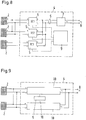
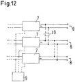
- the procedure can also be used in a system having a plurality of inverters 7, as in, for example, US Pat Fig. 10 is shown. With dashed lines 19 possible connections to the input parallel connection of the inverter 7 are shown here.
- the inputs described above are in this case the inputs of the inverters from the intermediate circuit 6.
- the control device 9 controls the inverters 7, ie switches them on or off as required to produce the required power states.
- the procedure described above can also be used if the outputs of the inverters 7 are connected in parallel. With dashed lines 20 possible connections are shown. One generates in this case a power at an output and measures whether the resulting Voltage at other outputs can be detected.
- the advantage of such a procedure is that one or more output stages, ie one or more inverters 7 can be switched off in order to save power when the input power is too low.
- the procedure works both with DC voltage and AC voltage. With AC voltage it is sufficient to determine the RMS value or another value which changes more slowly than with the frequency of the AC voltage, for example a peak voltage, if necessary averaged, an average of a rectified voltage or the like.
Description
Die Erfindung betrifft ein Verfahren zum Bestimmen einer Zusammenschaltungsart von mindestens zwei elektrischen Einrichtungen, von denen jede eine gleichartige Anschlußanordnung aufweist. Ferner betrifft die Erfindung ein System mit mehreren elektrischen Einrichtungen, von denen jede eine gleichartige Anschlußanordnung aufweist, und einer Steuereinrichtung.The invention relates to a method for determining an interconnection type of at least two electrical devices, each of which has a similar terminal arrangement. Furthermore, the invention relates to a system with a plurality of electrical devices, each having a similar terminal arrangement, and a control device.
Die Erfindung wird im folgenden anhand eines Systems beschrieben, bei dem mehrere Quellen von erneuerbarer Energie vorgesehen sind. Bei diesen Quellen handelt es sich um Einrichtungen, die Sonne, Wind, Wasserkraft oder andere natürlich vorkommende Energien in elektrische Energie umsetzen. Diese Energie wird auch als "grüne Energie" bezeichnet.The invention will be described below with reference to a system in which several sources of renewable energy are provided. These sources are devices that convert sun, wind, water or other naturally occurring energy into electrical energy. This energy is also called "green energy".
Die nachfolgende Beschreibung verwendet Solarzellen als Beispiel für die Erzeugung von grüner Energie. Solarzellen werden verwendet, um Sonnenlicht in elektrische Energie umzuwandeln. Solarzellen sind vielfach zu Paneelen zusammengefaßt, um eine höhere Spannung und auch Leistung zu erzeugen, als sie von einer einzelnen Solarzelle bereitgestellt werden könnte. Mehrere Paneele werden vielfach zu einem String in Reihe geschaltet.The following description uses solar cells as an example of the generation of green energy. Solar cells are used to convert sunlight into electrical energy. Solar cells are often grouped into panels to produce higher voltage and power than could be provided by a single solar cell. Several panels are often connected in series to form a string.
Eine typische Fotovoltaikanlage verwendet einen Solarzellen-String, der eine wechselnde elektrische Leistung zur Verfügung stellt. Diese Leistung hängt beispielsweise von der Sonneneinstrahlung (morgens, mittags, abends), von der Abschattung und auch von der Umgebungstemperatur ab. Diese Leistung wird durch einen Gleichstromwandler in eine konstante Zwischenkreis-spannung umgewandelt. Eine Wechselrichterstufe erzeugt dann eine Wechselspannung, die entweder unmittelbar genutzt werden kann, beispielsweise in Haushaltsgeräten, oder die in ein übergeordnetes Netz eingespeist werden kann. Dabei kann es sich sowohl um eine Einphasen-Spannung handeln als auch um eine Mehrphasen-Spannung.A typical photovoltaic system uses a solar cell string that provides varying electrical power. This power depends, for example, on the amount of sunlight (morning, noon, evening), shading and ambient temperature from. This power is converted by a DC-DC converter in a constant DC link voltage. An inverter stage then generates an AC voltage that can be used either directly, for example, in household appliances, or that can be fed into a higher-level network. This can be both a single-phase voltage and a multi-phase voltage.
Bei einem höheren Leistungsbedarf ist es vorteilhaft, wenn man mehrere voneinander getrennte Solarzellen-Strings in einem System hat. Diese Strings könnten dann parallel zueinander mit dem Eingang des Gleichstromwandlers verbunden werden. Diese Solarzellen-Strings werden jedoch nur dann ein im wesentlichen gleiches Verhalten an ihren Ausgängen zeigen, wenn sie vom gleichen Typ sind, die gleiche Größe haben, die gleiche Ausrichtung in Bezug auf die Sonne und die gleiche Abschattung. Dementsprechend werden sich in vielen Fällen die Ausgangsleistungen, beispielsweise die Ausgangsspannung, voneinander unterscheiden. Dies führt dann zu einer nicht optimalen Verwendung der Solarzellen-Strings.With a higher power requirement, it is advantageous to have several separate solar cell strings in one system. These strings could then be connected in parallel to the input of the DC-DC converter. However, these solar cell strings will show substantially the same behavior at their outputs only if they are the same type, the same size, the same orientation with respect to the sun, and the same shading. Accordingly, in many cases, the output powers, for example, the output voltage, will differ from each other. This then leads to a non-optimal use of the solar cell strings.
Man hat daher vorgeschlagen, die einzelnen Solarzellen-Strings jeweils mit eigenen Gleichstromwandlern auszurüsten. Die jeweiligen Gleichstromwandler speisen dann eine vorbestimmte Spannung in den Zwischenkreis des Leistungswandlers, beispielsweise über einen Spannungsbus.It has therefore been proposed to equip the individual solar cell strings each with their own DC converters. The respective DC-DC converters then feed a predetermined voltage into the DC link of the power converter, for example via a voltage bus.
Eine derartige Ausgestaltung ist beispielsweise aus
Andererseits gibt es Systeme oder Installationen, in denen die Solarzellen-Strings im Hinblick auf ihren Typ, ihre Größe, ihre Ausrichtung, Abschattung und andere Faktoren so ähnlich sind, daß sie Ausgangsgrößen, beispielsweise Ausgangsspannungen, produzieren, die mehr oder weniger identisch sind. In diesem Fall kann es vorteilhaft sein, nicht nur die Gleichstromwandler an ihren Ausgängen parallel zu schalten, sondern auch die Eingänge der Gleichstromwandler.On the other hand, there are systems or installations in which the solar cell strings are so similar in terms of their type, size, orientation, shading and other factors that they produce outputs, for example output voltages, which more or less are identical. In this case it may be advantageous to connect not only the DC-DC converters in parallel at their outputs but also the DC-DC inputs.
Ein Gleichstromwandler hat üblicherweise zwei Eigenschaften, die in mancher Hinsicht nachteilig sind.A DC-DC converter usually has two characteristics that are disadvantageous in some respects.
Zum einen gibt es eine obere Grenze für die Eingangsleistung, die nicht überschritten werden kann, ohne den Gleichstromwandler zu beschädigen. Zum anderen hat ein Gleichstromwandler vielfach einen verminderten Wirkungsgrad, wenn er mit niedriger Eingangsleistung arbeitet.First, there is an upper limit to the input power that can not be exceeded without damaging the DC-DC converter. On the other hand, a DC-DC converter often has a reduced efficiency when working with low input power.
Wenn man nun die einzelnen Solarzellen-Strings (im folgenden werden diese auch kurz als "Solarzellen" bezeichnet) mit mehreren Gleichstromwandlern verbindet, dann kann man zum einen dafür sorgen, daß die elektrische Leistung gleichmäßig auf die Gleichstromwandler verteilt wird. Zum anderen kann man einzelne Gleichstromwandler abschalten, wenn die elektrische Eingangsleistung zu niedrig wird. Ein Gleichstromwandler hat nämlich einen gewissen Grundverbrauch auch dann, wenn er keine elektrische Leistung wandelt. Die Abschaltung erfolgt über eine Steuereinrichtung in Abhängigkeit von der zugeführten elektrischen Energie.If one now connects the individual solar cell strings (hereinafter also referred to as "solar cells" for short) with a plurality of DC converters, then one can ensure on the one hand that the electrical power is uniformly distributed to the DC converters. On the other hand, you can switch off individual DC converters, if the electrical input power is too low. A DC-DC converter has a certain basic consumption even if it does not convert electrical power. The shutdown takes place via a control device as a function of the supplied electrical energy.
Die Steuereinrichtung muß nun "wissen", in welcher Konfiguration die einzelnen Gleichstromwandler in dem System angeordnet sind. Die Steuereinrichtung darf beispielsweise nur solche Gleichstromwandler abschalten, deren Solarzellen mit einem anderen Gleichstromwandler verbunden sind.The controller must now "know" what configuration the individual DC-DC converters are in the system. The control device may, for example, only switch off those DC converters whose solar cells are connected to another DC-DC converter.
Die Information kann man der Steuereinrichtung durch eine manuelle Eingabe zur Verfügung stellen. Ein Monteur kann beispielsweise einen Schalter umlegen oder einen Parameter über eine Tastatur eingeben. Dabei besteht jedoch in erheblichem Maße die Gefahr einer Falscheingabe, insbesondere bei größeren Fotovoltaik-anlagen, bei der mehrere hundert Solarzellen-Strings vorhanden sind.The information can be provided to the controller by manual input. For example, a fitter can flip a switch or enter a parameter via a keyboard. However, there is a considerable risk of incorrect input, in particular in larger photovoltaic systems, where several hundred solar cell strings are present.
Wenn die Steuereinrichtung fehlerhaft mit Informationen versorgt worden ist, kann dies zu einer ineffizienten Verwendung der Solarzellen-Strings führen.If the controller has been misinserted with information, it may result in inefficient use of the solar cell strings.
Der Erfindung liegt die Aufgabe zugrunde, die Zuverlässigkeit bei der Inbetriebnahme und im Betrieb eines Systems mit mehreren elektrischen Einrichtungen zu erhöhen.The invention has for its object to increase the reliability of commissioning and operation of a system with multiple electrical devices.
Diese Aufgabe wird bei einem Verfahren der eingangs genannten Art dadurch gelöst, daß man eine Spannung an der Anschlußanordnung einer ersten Einrichtung verändert und die veränderte Spannung als erste Spannung bestimmt, daß man zumindest an der Anschlußanordnung einer zweiten Einrichtung eine zweite Spannung bestimmt und daß man anhand eines Vergleichs der Spannungen bestimmt, ob zwischen den Anschlußanordnungen der Einrichtungen eine elektrische Verbindung besteht oder nicht.This object is achieved in a method of the type mentioned above in that one changes a voltage at the terminal arrangement of a first device and determines the changed voltage as the first voltage that at least at the terminal arrangement of a second device determines a second voltage and that by reference a comparison of the voltages determines whether or not there is an electrical connection between the terminal arrangements of the devices.
Mit dieser Vorgehensweise ist es möglich, in einem quasi automatisierten Verfahren zu bestimmen, ob die einzelnen elektrischen Einrichtungen mit ihren Anschlußanordnungen parallel geschaltet sind oder nicht. Bezogen auf die oben geschilderte Fotovoltaikanlage kann man also bestimmen, ob die einzelnen Solarzellen-Strings nur einzeln mit einem Gleichstromwandler verbunden sind oder ob mehrere Gleichstromwandler mit ihren Eingängen untereinander und mit den Solarzellen verbunden sind. Man macht sich dabei die Erkenntnis zunutze, daß die Veränderung einer Spannung an der Anschlußanordnung einer elektrischen Einrichtung eine entsprechende Veränderung der Spannung an der Anschlußanordnung einer anderen elektrischen Einrichtung mit sich bringt, wenn die beiden Anschlußanordnungen miteinander verbunden sind. Wenn eine Verbindung nicht besteht, dann wird eine Änderung an der Anschlußanordnung der ersten Einrichtung nicht zu einer entsprechenden Änderung der Spannung an der Anschlußanordnung der anderen Einrichtung führen. Dies gilt vor allem dann, wenn die Anschlußanordnungen direkt miteinander verbunden sind, also keine weiteren Baugruppen (abgesehen von Leitungen und Verbindern) zwischen den Anschlußanordnungen angeordnet sind.With this approach, it is possible to determine in a quasi-automated process whether the individual electrical devices are connected in parallel with their terminal arrangements or not. Based on the photovoltaic system described above, it is thus possible to determine whether the individual solar cell strings are only individually connected to a DC-DC converter or whether several DC-DC converters with their inputs are connected to each other and to the solar cells. One makes use of the knowledge that the change of a voltage at the terminal arrangement of an electrical device brings about a corresponding change in the voltage at the terminal arrangement of another electrical device when the two terminal arrangements connected to each other. If a connection does not exist then a change in the terminal arrangement of the first device will not result in a corresponding change in the voltage across the terminal arrangement of the other device. This is especially true when the terminal assemblies are connected directly to each other, so no further modules (apart from cables and connectors) are arranged between the terminal assemblies.
Vorzugsweise wird die Spannung an der ersten Einrichtung verändert, indem man die erste Einrichtung belastet. Insbesondere bei Quellen erneuerbarer Energie, beispielsweise Solarzellen, gibt es einen gewissen Innenwiderstand. Die Spannung sinkt also bei Belastung von einer Leerlaufspannung auf eine Betriebsspannung. Wenn die Anschlußanordnungen von zwei Einrichtungen miteinander verbunden sind, dann wirkt sich die Belastung auf beide Einrichtungen aus, so daß die Spannungen an beiden Einrichtungen absinken werden. Wenn eine derartige Verbindung zwischen den Anschlußanordnungen hingegen nicht besteht, dann werden sich die Spannungen nicht entsprechend ändern.Preferably, the voltage at the first device is changed by loading the first device. Especially with sources of renewable energy, such as solar cells, there is a certain internal resistance. The voltage thus drops under load from an open circuit voltage to an operating voltage. If the terminal assemblies of two devices are connected together, then the load on both devices will affect so that the voltages on both devices will drop. On the other hand, if such a connection does not exist between the terminal assemblies, then the voltages will not change accordingly.
Vorzugsweise wiederholt man die Bestimmung und verwendet als erste Einrichtung in aufeinanderfolgenden Bestimmungen eine andere Einrichtung. Man kann die Bestimmung beispielsweise bei jeder Inbetriebnahme wiederholen oder immer dann, wenn die Anlage oder das System anfängt, elektrische Leistung in ein übergeordnetes Netz einzuspeisen. Damit wird sichergestellt, daß eine Änderung der Konfiguration nicht übersehen werden kann, die möglicherweise in Betriebspausen erfolgt ist. Eine derartige Änderung kann auch ungewollt erfolgen. Dabei kann es von Vorteil sein, wenn man nicht immer die gleiche Einrichtung als erste Einrichtung verwendet, sondern man sozusagen durchwechselt.Preferably, the determination is repeated and uses as the first means in successive determinations another means. For example, the determination can be repeated every time the system is put into operation, or whenever the system or system begins to feed electrical power into a higher-level network. This ensures that you can not overlook a change in the configuration that may have occurred during breaks. Such a change can also take place unintentionally. It may be advantageous if you do not always use the same device as the first device, but you can substitute so to speak.
Bevorzugterweise verwendet man als Anschlußanordnung eine Eingangs-Anschlußanordnung, die jeweils mit einer Energiequelle verbunden ist. Auf diese Weise verwendet man den Innenwiderstand der Energiequelle, um die Spannungsänderung zu bewirken.Preferably, the terminal arrangement used is an input terminal arrangement, which is in each case connected to a power source. In this way one uses the internal resistance of the energy source to effect the voltage change.
Hierbei ist bevorzugt, daß man als Energiequelle eine Quelle erneuerbarer Energie verwendet. Eine derartige Quelle wird auch als regenerative Energiequelle oder Quelle regenerativer Energie bezeichnet. Bei einer derartigen Quelle stellt sich das Problem in besonderem Maße.It is preferred that one uses a source of renewable energy as an energy source. Such a source is also referred to as a regenerative energy source or source of regenerative energy. In such a source, the problem is particularly significant.
Alternativ dazu kann man als Anschlußanordnung auch eine Ausgangs-Anschlußanordnung verwenden. In diesem Fall wird beispielsweise der Innenwiderstand der elektrischen Einrichtung zur Änderung der Ausgangsspannung verwendet.Alternatively, an output terminal arrangement may be used as the terminal arrangement. In this case, for example, the internal resistance of the electrical device is used to change the output voltage.
In einer bevorzugten Ausgestaltung ist vorgesehen, daß man dann, wenn man bei einer Bestimmung feststellt, daß die erste Einrichtung nicht mit einer anderen Einrichtung verbunden ist, eine andere Einrichtung als erste Einrichtung verwendet und sie in Bezug auf die verbleibenden Einrichtungen testet. Damit stellt man sicher, daß man auch unterschiedliche Verbindungsarten erfaßt. In einem System oder einer Anlage können durchaus mehrere Einrichtungen parallel geschaltet sein, während andere Einrichtungen isoliert betrieben werden. Dies kann man mit der vorgeschlagenen Vorgehensweise zuverlässig ermitteln.In a preferred embodiment it is provided that, if it is determined in one determination that the first device is not connected to another device, one uses a device other than the first device and tests it with respect to the remaining devices. This ensures that you can also detect different types of connection. In a system or plant, several devices may be connected in parallel, while other devices are operated in isolation. This can be reliably determined with the proposed procedure.
Hierbei ist bevorzugt, daß man die Bestimmungen wiederholt und solange eine andere Einrichtung als erste Einrichtung verwendet, bis alle bis auf eine Einrichtung als erste Einrichtung verwendet worden sind. Man testet also sozusagen sämtliche Verbindungen durch, um festzustellen, ob irgendwo parallele Verbindungen existieren, d.h. die Anschlußanordnungen miteinander verbunden sind oder nicht.It is preferred that the determinations are repeated and that another device is used as the first device until all but one device have been used as the first device. So you test all connections so to speak, to determine whether somewhere parallel connections exist, ie the terminal arrangements are connected or not.
In einer bevorzugten Ausgestaltung ist vorgesehen, daß man mehrere Einrichtungen, die ein gleichartiges Verhalten aufweisen und deren Anschlußanordnungen miteinander verbunden sind, gemeinsam als erste Einrichtung verwendet. In diesem Fall ist es bereits bekannt, daß diese Einrichtungen miteinander verbunden sind. Man kann dann eine Gruppe von Einrichtungen als "Master" verwenden und überprüfen, ob die verbleibenden Einrichtungen parallel mit dieser Gruppe geschaltet sind oder nicht.In a preferred embodiment, it is provided that a plurality of devices having a similar behavior and their terminal arrangements are interconnected, used together as the first device. In this case, it is already known that these devices are interconnected. One can then use a group of devices as "masters" and check whether the remaining devices are connected in parallel with this group or not.
Auch ist von Vorteil, wenn man bei einer Wechselspannung einen charakteristischen Wert ermittelt. Der charakteristische Wert ist ein Wert, der sich nicht mit der gleichen Frequenz ändert wie die Wechselspannung, beispielsweise der Effektivwert, eine gemittelte Scheitel-Scheitel-Spannung oder ein gleichgerichteter Mittelwert. Ein derartiger Wert läßt sich relativ leicht ermitteln. Er ist eine ausreichend aussagekräftige Größe, um die obengenannten Bestimmungen durchzuführen.It is also advantageous if a characteristic value is determined for an alternating voltage. The characteristic value is a value that does not change with the same frequency as the AC voltage, for example the RMS value, an average peak-to-peak voltage or a rectified mean value. Such a value can be determined relatively easily. He is a sufficiently meaningful size to carry out the above-mentioned provisions.
Die Erfindung wird bei einem System der eingangs genannten Art dadurch gelöst, daß an jeder Anschlußanordnung ein Sensor angeordnet ist, der mit der Steuereinrichtung verbunden ist, wobei die Steuereinrichtung Mittel, um die Spannung an jeder Anschlußanordnung zu verändern, einen Vergleicher, um Spannungen an verschiedenen Anschlußanordnungen miteinander zu vergleichen, und eine Speichereinrichtung aufweist, in der sie in Abhängigkeit vom Ausgangssignal des Vergleichers speichert, ob Anschlußanordnungen von elektrischen Einrichtungen miteinander verbunden sind oder nicht.The invention is achieved in a system of the type mentioned above in that a sensor is arranged on each terminal arrangement, which is connected to the control device, wherein the control means for changing the voltage at each terminal arrangement, a comparator to voltages at different Compare terminal arrangements with each other, and having a memory means in which it stores in dependence on the output signal of the comparator, whether or not connection arrangements of electrical devices are connected to each other.
Die Steuereinrichtung führt also das oben beschriebene Verfahren aus und "merkt sich", welche elektrischen Einrichtungen miteinander verbunden sind und welche nicht. Dabei kann es durchaus vorkommen, daß es mehrere Gruppen von miteinander verbundenen elektrischen Einrichtungen gibt. Die Steuereinrichtung hat dann die Möglichkeit, in jeder Gruppe die einzelnen Einrichtungen so zu steuern, wie dies für eine optimale Betriebsweise günstig ist.The control device thus carries out the method described above and "remembers" which electrical devices are connected to one another and which are not. It may well happen that there are several groups of interconnected electrical facilities gives. The control device then has the option of controlling the individual devices in each group in a manner that is favorable for optimum operation.
Vorzugsweise sind die elektrischen Einrichtungen als Gleichstromwandler ausgebildet. Die Steuereinrichtung kann dann, wenn die Gleichstromwandler miteinander verbunden sind, einzelne Gleichstromwandler abschalten, wenn die Eingangsleistung nicht ausreicht.Preferably, the electrical devices are designed as DC converters. The controller may, when the DC-DC converters are connected to each other, switch off individual DC-DC converters if the input power is insufficient.
Bevorzugterweise sind die Ausgangs-Anschlußanordnungen der Gleichstromwandler parallel geschaltet. Die Gleichstromwandler haben also eine gemeinsame Ausgangsspannung.Preferably, the output terminal arrangements of the DC-DC converter are connected in parallel. The DC-DC converters thus have a common output voltage.
Vorzugsweise sind die Ausgangs-Anschlußanordnungen mit einem Wechselrichter verbunden. Die Gleichstromwandler speisen also einen Zwischenkreis, aus dem der Wechselrichter die elektrische Leistung entnimmt.Preferably, the output terminal assemblies are connected to an inverter. Thus, the DC-DC converters feed a DC link from which the inverter draws the electrical power.
In einer alternativen Ausgestaltung ist vorgesehen, daß die elektrischen Einrichtungen als Wechselrichter ausgebildet sind. Hier gilt im Grunde das Gleiche.In an alternative embodiment, it is provided that the electrical devices are designed as inverters. Here is basically the same thing.
Dabei ist von Vorteil, wenn die Ausgangs-Anschluß-anordnungen der Wechselrichter parallel geschaltet sind. Auch dann läßt sich bei einem derartigen System feststellen, welche Wechselrichter an ihren Ausgängen parallel geschaltet sind und gemeinsam betrieben werden können und welche im individuellen Betrieb verwendet werden müssen.It is advantageous if the output terminal arrangements of the inverters are connected in parallel. Even then can be in such a system determine which inverters are connected in parallel at their outputs and can be operated together and which must be used in individual operation.
Bevorzugterweise sind die Anschlußanordnungen als Eingangs-Anschlußanordnungen ausgebildet, die jeweils mit einer Quelle erneuerbarer Energie verbunden sind. Bei dieser Quelle kann es sich beispielsweise um Solarzellen-Strings, um Windkraftanlagen, um Wasserkraftanlagen, um Brennstoffzellen oder ähnliches handeln.Preferably, the terminal assemblies are formed as input terminal assemblies, each connected to a source of renewable energy. For example, this source may be solar cell strings, to wind turbines, to hydropower plants, to fuel cells or the like.
Die Erfindung wird im folgenden anhand von bevorzugten Ausführungsbeispielen in Verbindung mit der Zeichnung beschrieben. Hierin zeigen:
- Fig. 1
- eine schematische Darstellung zur Erläuterung einer Anlage mit einem Solarzellen-String,
- Fig. 2
- eine Anlage mit mehreren Solarzellen-Strings,
- Fig. 3
- eine Anlage mit mehreren Solarzellen-Strings, von denen jeder einen eigenen Gleichstromwandler aufweist,
- Fig. 4
- eine mögliche Verschaltung einer Anlage nach
Fig. 3 , - Fig. 5
- ein Flußdiagramm,
- Fig. 6
- eine erste Beschaltung der Anlage nach
Fig. 4 , - Fig. 7
- eine zweite Beschaltung der Anlage nach
Fig. 4 , - Fig. 8
- eine dritte Beschaltung der Anlage nach
Fig. 4 , - Fig. 9
- eine abgewandelte Ausführungsform einer Anlage mit mehreren Solarzellen-Strings,
- Fig. 10
- eine weitere Abwandlung einer Anlage im Ausschnitt,
- Fig. 11
- eine Einrichtung zum Ändern der Spannung an einem Gleichspannungswandler und
- Fig. 12
- eine weitere Abwandlung einer Konfiguration im Ausschnitt.
- Fig. 1
- a schematic representation for explaining a system with a solar cell string,
- Fig. 2
- a plant with several solar cell strings,
- Fig. 3
- a system with multiple solar cell strings, each with its own DC converter,
- Fig. 4
- a possible interconnection of a system after
Fig. 3 . - Fig. 5
- a flowchart,
- Fig. 6
- a first wiring of the plant after
Fig. 4 . - Fig. 7
- a second wiring of the plant after
Fig. 4 . - Fig. 8
- a third wiring of the plant after
Fig. 4 . - Fig. 9
- a modified embodiment of a system with multiple solar cell strings,
- Fig. 10
- a further modification of a plant in the neck,
- Fig. 11
- a device for changing the voltage across a DC-DC converter and
- Fig. 12
- another variation of a configuration in the neckline.
Das System 1 weist einen String 2 mit schematisch dargestellten Solarzellen 3 auf. Üblicherweise ist jeweils eine Vielzahl von Solarzellen 3 auf einem Paneel oder Tableau angeordnet. Mehrere derartiger Paneele bilden dann in Reihe den String 2. Am Ausgang des Strings 2 liefern die Solarzellen 3 eine Gleichspannung. Die Spannungsstärke variiert hierbei, beispielsweise in Abhängigkeit von der Sonneneinstrahlung, der Abschattung, der Umgebungstemperatur oder anderer Einflüsse.The system 1 has a
Der String 2 ist mit einem Leistungswandler 4 verbunden, der auch als Leistungsumsetzer bezeichnet werden kann. Der Leistungswandler 4 weist zunächst einen Gleichstromwandler 5 auf. Der Gleichstromwandler 5 wandelt die veränderliche Gleichspannung, die vom String 2 geliefert wird, in eine konstante Gleichspannung um und gibt sie an einen Zwischenkreis 6 aus. Der Zwischenkreis 6 ist mit einem Wechselrichter 7 verbunden, der die Gleichspannung aus dem Zwischenkreis 6 in eine ein- oder mehrphasige Wechselspannung umwandelt und diese an ein Netz 8 ausgibt.The
Wenn die Ausgangsleistung eines einzelnen Strings nicht ausreicht, dann kann man, wie in
Eine Anordnung wie in
Die Ausgestaltung nach
Aus diesem Grund wird vielfach bevorzugt, die einzelnen Strings 2 schon vor den Gleichstromwandlern 5 parallel zu schalten, also ihre Ausgänge miteinander zu verbinden, und die Gleichstromwandler 5 dann in den gemeinsamen Zwischenkreis 6 speisen zu lassen.For this reason, it is often preferred to switch the
In diesem Fall ist eine Steuereinrichtung 9 erforderlich. Die Steuereinrichtung 9 steuert, wie dies mit gestrichelten Leitungsstrecken 10 angedeutet ist, die einzelnen Gleichstromwandler 5 bedarfsabhängig. Die Parallelschaltung der einzelnen Strings 2 ermöglicht es, die von den Strings 2 abgegebenen elektrischen Leistungen auf die Gleichstromwandler 5 zu verteilen, so daß eine Überlastung nicht zu befürchten ist. Andererseits kann die Steuereinrichtung 9 auch einzelne Gleichstromwandler einfach abschalten, wenn die von den Strings 2 gelieferte elektrische Leistung zu gering ist. In diesem Fall wird die Verlustleistung, die jeder Gleichstromwandler 5 benötigt, bei den abgeschalteten Gleichstromwandlern 5 eingespart.In this case, a
Bei der Montage einer Anlage kann es nun vorkommen, daß einzelne Verbindungen zwischen den Ausgängen von Strings 2 nicht ordnungsgemäß hergestellt werden oder mit Absicht weggelassen werden. Auch im Betrieb kann es vorkommen, daß eine derartige Verbindung unterbrochen wird, beispielsweise durch einen Sturm, einen Wasserschaden oder ein anderes natürliches Ereignis. Auch menschliche Eingriffe sind möglich. Drei unterschiedliche Konstellationen, die sich dann ergeben können, sind in den
Damit die Steuereinrichtung 9 feststellen kann, in welcher Konfiguration die Strings 2 mit dem Leistungswandler 4 verbunden sind, ist an der Eingangs-Anschlußan-ordnung 11 eines jeden Gleichstromwandlers 5 ein Sensor 12 angeordnet, der mit der Steuereinrichtung 9 über strichpunktiert dargestellte Leitungsstrecken 13 verbunden ist. Die Leitungsstrecken 10, 13 können unterschiedliche Ausgestaltungen haben. Es kann sich um elektrische Leitungen handeln oder um optische Leitungen. Man kann die entsprechenden Strecken zwischen der Steuereinrichtung 9, den Gleichstromwandlern 5 und den Sensoren 12 auch leitungslos ausbilden und die entsprechende Signalübertragung dann über elektromagnetische Wellen, Licht, Schall oder ähnliches bewirken.So that the
Der Sensor 12 an der Eingangs-Anschlußanordnung 11 des Gleichstromwandlers 5 ist hier als getrenntes Element ausgebildet. Es versteht sich aber, daß die Steuereinrichtung 9 die entsprechende Information auch im Gleichstromwandler 5 unmittelbar erfahren kann, beispielsweise über eine Spannungsmessung an der Eingangs-Anschlußanordnung 11.The
Damit die Steuereinrichtung 9 nun feststellen kann, in welcher Konfiguration die Strings 2 mit dem Leistungswandler 4 verbunden sind, führt sie zumindest nach der Inbetriebnahme, vorzugsweise aber öfters, beispielsweise nach jeder leistungsfreien Periode oder in regelmäßigen Abständen, einen Algorithmus durch, der sich kurz wie folgt beschreiben läßt:So that the
Die Steuereinrichtung 9 wählt einen ersten Gleichstromwandler 5 aus und senkt die Spannung dort ab. Dies erfolgt vorzugsweise dadurch, daß die Steuereinrichtung den Gleichstromwandler so steuert, daß er elektrische Energie in den Zwischenkreis 6 liefert. Ein anderes Mittel hierzu ist schematisch in
Die Steuereinrichtung 9 wählt also einen Gleichstromwandler 5 als "Master". Die verbleibenden Gleichstromwandler 5 werden als "Slave" behandelt. Der Master wird in Betrieb genommen, indem an seinem Eingang Leistung entnommen wird. Die Slaves werden in einen Zustand versetzt, wo eine derartige Leistungsentnahme nicht stattfindet. Am Master wird die Spannung von einer Leerlaufspannung, also die Leerlaufspannung des mit dem Master verbundenen Strings 2, absinken, da der String 2 einen Innenwiderstand hat. Die an der Eingangs-Anschlußanord-nung 11 entnommene Leistung wird so lange gesteigert, bis die Eingangsspannung am Master bis auf einen vorbestimmten Anteil der Leerlaufspannung abgefallen ist. Nach einer vorbestimmten Zeit wird die Spannungsdifferenz zwischen dem Master und jedem Slave berechnet oder auf andere Weise bestimmt. Wenn bei einer Ausgangsspannung von beispielsweise 80 V eines Strings 2 die Unterschiede größer als 15 V sind, dann kann man annehmen, daß es keine parallele Verbindung der Strings 2 zu den Gleichstromwandlern 5 gibt. Wenn der Unterschied kleiner als 10 V ist, kann man annehmen, daß es eine parallele Verbindung zwischen den Eingängen des Masters und des Slave gibt.The
Ein entsprechender Algorithmus ist schematisch in
Wenn es noch ungetestete Gleichstromwandler 5 gibt, wird der nächste Gleichstromwandler 5 in einem Schritt 29 getestet. Wurde dieser Test unterbrochen (Entschei-dung 30), kehrt man zum Schritt 25 zurück. In einer Entscheidung 31 wird überprüft, ob der Test bis zum Ende durchgeführt worden ist. Wenn dies der Fall ist, wird in einem Schritt 32 für jeden Gleichstromwandler 5 der Betriebsmodus festgelegt, also individueller Betrieb oder Betrieb in Parallelschaltung mit anderen Gleichstromwandlern 5.If there are still untested DC-
Dies soll nachfolgend anhand der
In
Wenn der Leistungswandler 4 mit dem Netz 8 verbunden wird, wird die Kalibrierung durchgeführt, während der alle Gleichstromwandler 5 ausgeschaltet sind.When the power converter 4 is connected to the
Danach wird DC1 eingeschaltet, um Energie zu liefern, während DC2 und DC3 ausgeschaltet bleiben. Nach einer vorbestimmten Zeit, beispielsweise 45 Sekunden, weiß die Steuereinrichtung 9, daß DC1 nicht parallel mit DC2 oder DC3 geschaltet ist. Deswegen darf DC1 weiter Energie erzeugen. Die Speichereinrichtung 9 merkt sich, daß DC1 einzeln angeordnet ist.After that, DC1 is turned on to provide power while DC2 and DC3 remain off. After a predetermined time, for example 45 seconds, the
Danach wird DC2 eingeschaltet und liefert Energie. DC3 bleibt ausgeschaltet. Nach einer vorbestimmten Zeit weiß die Steuereinrichtung 9, daß DC2 und DC3 nicht parallel geschaltet sind, weil sich am Eingang von DC3 keine Spannungsänderung ergeben hat. DC2 darf weiter Energie erzeugen (d.h. liefern) in der individuellen Betriebsweise.Then DC2 is switched on and supplies energy. DC3 remains off. After a predetermined time, the
Da DC3 der letzte ungetestete Gleichstromwandler 5 ist, kann er nicht parallel mit irgendeinem anderen Gleichstromwandler 5 geschaltet sein. Aus diesem Grund merkt sich die Steuereinrichtung 9, daß DC3 ebenfalls in der individuellen Betriebsweise betrieben wird und DC3 kann weiter Energie erzeugen. Mit "Energie erzeugen" ist hier gemeint, daß die Gleichstromwandler 5 den Strom von den Strings 2 der Solarzellen 3 in den Zwischenkreis 3 einspeisen.Since DC3 is the last untested DC-
Der Leistungswandler 4 wird mit dem Netz 8 verbunden. Die Kalibrierung wird durchgeführt, während alle Gleichstromwandler 5 ausgeschaltet sind. Der Gleichstromwandler DC1 wird eingeschaltet, d.h. an seinem Eingang belastet. Die beiden Gleichstromwandler DC2 und DC3 bleiben ausgeschaltet. Nach einer vorbestimmten Zeit weiß die Steuereinrichtung 9, daß DC1 parallel mit DC2 und DC3 ist. Alle drei Gleichstromwandler 5 werden also als parallel geschaltet vermerkt. Da kein ungetesteter Gleichstromwandler 5 verbleibt, ist der Test ausgeführt.
The power converter 4 is connected to the
In
Der Leistungswandler 4 wird mit dem Netz 8 verbunden. Die Kalibrierung wird durchgeführt, während alle Gleichstromwandler 5 ausgeschaltet sind.In
The power converter 4 is connected to the
DC1 wird eingeschaltet, während DC2 und DC3 ausgeschaltet sind. Nach einer vorbestimmten Zeit wird das System wissen, daß DC1 parallel mit DC2 geschaltet ist. DC1 und DC2 werden als parallel geschaltet gespeichert.
Da DC3 der letzte ungetestete Gleichstromwandler 5 ist, kann er nicht parallel mit irgendeinem anderen Gleichstromwandler 5 geschaltet sein. DC3 wird dann als individueller Gleichstromwandler betrieben. Da keine ungetesteten Gleichstromwandler 5 verbleiben, ist der Test ausgeführt.DC1 is turned on while DC2 and DC3 are off. After a predetermined time, the system will know that DC1 is in parallel with DC2. DC1 and DC2 are stored as connected in parallel.
Since DC3 is the last untested DC-
Die Spannung, auf die der Eingang des Masters abgesenkt wird, hängt von den Eigenschaften der Leistungsquelle, im vorliegenden Fall der Strings 2 ab. Darüber hinaus kann auch die Empfindlichkeit der Spannungsmessungstechnik eine Rolle spielen, die Genauigkeit der Spannungsmessung und ähnliche Faktoren. Wenn man beispielsweise einen 3 kW-Wandler verwendet, der mit einem String 2 aus Solarzellen betrieben wird, dann ist beispielsweise eine Spannung von 80 % der Leerlaufspannung geeignet.The voltage to which the input of the master is lowered depends on the characteristics of the power source, in the present case the
Die vorbestimmte Zeit, die man verstreichen läßt, um einen stabilen Zustand zu erzeugen, d.h. um zu überprüfen, ob die Spannungen sich gleich oder unterschiedlich entwickelt haben, hängen von den transienten Eigenschaften des Systems ab. In dem obengenannten Beispiel eines 3 kW-Wandlers kann man beispielsweise eine Periode von 45 Sekunden als ausreichend für die Stabilisierung der Spannung ansehen.The predetermined time allowed to elapse to produce a stable state, i. to check whether the voltages have evolved the same or different, depends on the transient properties of the system. For example, in the above example of a 3 kW converter, one may consider a period of 45 seconds to be sufficient for the stabilization of the voltage.
Wie oben bereits ausgeführt, steht die Steuereinrichtung 9 mit den Gleichstromwandlern 5 über Leitungsstrecken in Verbindungen. Sie können analog oder digital ausgeführt sein, als Bussystem oder drahtlos. Auch die Signale der Sensoren 12 können entsprechend übertragen werden.As already stated above, the
Die Steuereinrichtung 9 muß nicht physikalisch von den Gleichstromwandlern 5 getrennt sein. Sie könnte beispielsweise mit einem der Wandler zusammengebaut sein und von dort die übrigen Gleichstromwandler 5 steuern mit Hilfe von den oben beschriebenen Leitungsstrecken.The
Die Steuereinrichtung 9 kann in einer vorteilhaften Ausgestaltung jedesmal mit einem anderen Gleichstromwandler 5 starten, d.h. beim ersten Test mit DC1, beim zweiten Test mit DC2, beim dritten Test mit DC3 und beim vierten Test wieder mit DC1. Damit kann man Fehler ausmitteln.The
Die Vorgehensweise funktioniert auch dann, wenn zwei oder mehr Gleichstromwandler mit ihren verbundenen Strings 2 von Gleichstromzellen 3 als Mastereinheit arbeiten. In diesem Fall stellt die Steuereinrichtung sicher, daß die Last in einer bestimmten Art auf die Gleichstromwandler 5 verteilt wird. In diesem Fall würde man bestimmen, ob der Eingang eines Gleichstromwandlers 5, der nicht zu dieser Mastereinheit gehört, parallel zu dem Eingang irgendeines Gleichstromwandlers 5 geschaltet ist, der zu der Mastereinheit gehört.The procedure also works when two or more DC-DC converters with their associated
Man kann auch eine Mehrzahl von Steuereinrichtungen 9 verwenden, beispielsweise eine in jedem Gleichstromwandler 5. Diese unterschiedlichen Steuereinrichtungen 9 können dann zusammenarbeiten, um zu entscheiden, welcher Gleichstromwandler 5 als Master und welcher als Slave arbeiten soll.It is also possible to use a plurality of
Die Vorgehensweise kann auch verwendet werden, wenn der Leistungswandler 4 Einheiten 18 verwendet, die die Leistung aus den Strings 2 unmittelbar in das Netz 8 speisen, d.h. ohne einen herausgeführten Gleichspannungszwischenkreis 6.The approach may also be used when the power converter uses 4
Die Vorgehensweise kann man auch verwenden in einem System, das eine Vielzahl von Wechselrichtern 7 aufweist, wie dies beispielsweise in
Die oben beschriebene Vorgehensweise kann man auch dann verwenden, wenn die Ausgänge der Wechselrichter 7 parallel geschaltet sind. Mit gestrichelten Linien 20 sind mögliche Verbindungen dargestellt. Man erzeugt in diesem Fall eine Leistung an einem Ausgang und mißt, ob die sich ergebende Spannung an anderen Ausgängen erfaßbar ist. Der Vorteil einer derartigen Vorgehensweise besteht darin, daß man eine oder mehrere Ausgangsstufen, d.h. einen oder mehrere Wechselrichter 7 abschalten kann, um Leistung zu sparen, wenn die Eingangsleistung zu gering ist.The procedure described above can also be used if the outputs of the
Es wurde oben beschrieben, daß die Spannung abgesenkt wurde, um festzustellen, ob Einheiten parallel geschaltet sind oder nicht. Natürlich kann man auch die Spannung anheben.It has been described above that the voltage has been lowered to see if units are connected in parallel or not. Of course you can also raise the tension.
Die Vorgehensweise funktioniert sowohl bei Gleichspannung als auch bei Wechselspannung. Bei Wechselspannung reicht es aus, den Effektivwert zu ermitteln oder einen anderen Wert, der sich langsamer ändert als mit der Frequenz der Wechselspannung, beispielsweise eine Scheitelspannung, ggf. gemittelt, ein Mittelwert einer gleichgerichteten Spannung oder dergleichen.The procedure works both with DC voltage and AC voltage. With AC voltage it is sufficient to determine the RMS value or another value which changes more slowly than with the frequency of the AC voltage, for example a peak voltage, if necessary averaged, an average of a rectified voltage or the like.
Claims (16)
- A method for determining a type of interconnection of at least two electrical devices, each comprising a similar terminal arrangement being connected in each case to at least one energy source comprising solar cells, characterized in that a voltage at the terminal arrangement of a first device is changed by loading the energy source connected to the first device by the first device, the change in voltage being determined as the first voltage change, and a second voltage change is determined at least at the terminal arrangement of a second device as a result of the loading, and wherein it is determined by comparing the voltage changes whether or not an electrical connection exists between the terminal arrangements of the devices.
- The method according to claim 1, wherein the determination is repeated and another device is used as the first device in successive determinations.
- The method according to claim 1 or 2, wherein an input terminal arrangement is used as the terminal arrangement.
- The method according to any one of claims 1 to 3, wherein one of the two devices is deactivated at low power only if there is an electrical connection between the terminal arrangements of the devices.
- The method according to any one of claims 1 to 2, wherein an output terminal arrangement is used as the terminal arrangement.
- The method according to any one of claims 1 to 5, wherein a device different to the first device is used and tested relative to the remaining devices, when a determination results in that the first device is not electrically connected to any other device.
- The method according to claim 6, wherein the deteminations are repeated and another device is used as the first device until all but one device have been used as the first device.
- The method according to any one of claims 1 to 7, wherein several devices having similar behaviour and whose terminal arrangements are interconnected are jointly used as the first device.
- The method according to any one of claims 1 to 8, a characteristic value being determined for an alternating voltage.
- A system with a plurality of electrical devices (5), each comprising a similar terminal arrangement (11), and a control device (9), wherein at least one solar cell string is connected to each of the terminal arrangements, characterized in that a sensor (12) connected to the control device (9) is arranged on each terminal arrangement (11), the control device (9) comprising means for changing the voltage at each terminal arrangement (11) by loading the solar cells, a comparator for comparing voltage changes resulting from the above loading to voltages at different terminal arrangements (11), and a memory device (17) storing whether or not terminal arrangements (11) of electrical devices (5) are connected to each other depending on the output signal of the comparator.
- The system according to claim 10, wherein the electrical means (5) is provided as a DC-DC converter.
- The system according to claim 11, wherein the output terminal arrangements of the DC-DC converters (5) are connected in parallel.
- The system according to claim 12, wherein the output terminal arrangements are connected to an inverter (7).
- The system according to claim 10, wherein the electrical devices (5) are provided as inverters.
- The system according to claim 14, wherein the output terminal arrangements of the inverters are connected in parallel.
- The system according to any one of claims 10 to 15, wherein the terminal arrangements (11) are provided as input terminal arrangements, each connected to a source (2) of renewable energy.
Applications Claiming Priority (2)
| Application Number | Priority Date | Filing Date | Title |
|---|---|---|---|
| DE102005028513.9A DE102005028513B4 (en) | 2005-06-17 | 2005-06-17 | Method for determining an interconnection type of at least two electrical devices and system with several electrical devices |
| PCT/DK2006/000347 WO2006133714A1 (en) | 2005-06-17 | 2006-06-15 | Method for determining the type of connection of at least two electrical devices and system comprising several electric devices |
Publications (2)
| Publication Number | Publication Date |
|---|---|
| EP1891723A1 EP1891723A1 (en) | 2008-02-27 |
| EP1891723B1 true EP1891723B1 (en) | 2018-11-21 |
Family
ID=37036768
Family Applications (1)
| Application Number | Title | Priority Date | Filing Date |
|---|---|---|---|
| EP06753314.1A Active EP1891723B1 (en) | 2005-06-17 | 2006-06-15 | Method for determining the type of connection of at least two electrical devices and system comprising several electric devices |
Country Status (6)
| Country | Link |
|---|---|
| US (2) | US7965088B2 (en) |
| EP (1) | EP1891723B1 (en) |
| KR (1) | KR100974176B1 (en) |
| CN (1) | CN101253665B (en) |
| DE (1) | DE102005028513B4 (en) |
| WO (1) | WO2006133714A1 (en) |
Families Citing this family (22)
| Publication number | Priority date | Publication date | Assignee | Title |
|---|---|---|---|---|
| US8624439B2 (en) * | 2007-06-06 | 2014-01-07 | Power-One Italy S.P.A. | Delivery of electric power by means of a plurality of parallel inverters and control method based on maximum power point tracking |
| JP5643104B2 (en) * | 2007-11-30 | 2014-12-17 | アレンコン・アクイジション・カンパニー・エルエルシー | Multiphase grid synchronous adjustment current source inverter system |
| FR2940476B1 (en) * | 2008-12-18 | 2011-02-25 | Total Sa | ELECTRONIC MANAGEMENT SYSTEM FOR PHOTOVOLTAIC CELLS |
| ES2374462B1 (en) * | 2009-02-18 | 2012-09-27 | Montajes Y Proyectos Electrotécnicos, S.L. | DEVICE FOR DETERMINATION OF VOLTAGE AND CURRENTS DELIVERED BY A PHOTOVOLTAIC PANEL, PROVISIONED INSTALLATION OF SUCH DEVICE AND PROCEDURE FOR ADAPTATION OF IMPEDANCE FROM SUCH DEVICE. |
| IT1394682B1 (en) * | 2009-07-10 | 2012-07-13 | Agostinelli | APPARATUS AND METHOD FOR THE UNCOUPLED SUPPLY OF ELECTRONIC CIRCUITS. |
| FR2953996B1 (en) * | 2009-12-11 | 2012-01-20 | Centre Nat Rech Scient | ELECTRONIC MANAGEMENT SYSTEM OF PHOTOVOLTAIC CELLS FUNCTION OF METEOROLOGY |
| WO2012041317A2 (en) * | 2010-09-27 | 2012-04-05 | Danfoss Solar Inverters A/S | Photovoltaic power plant |
| US9350166B2 (en) | 2010-10-05 | 2016-05-24 | Alencon Acquisition Co., Llc | High voltage energy harvesting and conversion renewable energy utility size electric power systems and visual monitoring and control systems for said systems |
| US9086443B2 (en) * | 2010-10-12 | 2015-07-21 | Dsp Group Ltd. | Detecting a connection type of a pin |
| DE102010050785B4 (en) * | 2010-11-10 | 2015-02-12 | Sma Solar Technology Ag | Method for verifying an electrical connection in a power plant |
| KR101104922B1 (en) * | 2010-12-24 | 2012-01-12 | 한양전공주식회사 | Solar power plant system |
| AU2012253314B2 (en) | 2011-05-12 | 2016-11-24 | Alencon Acquisition Co., Llc | High voltage energy harvesting and conversion renewable energy utility size electric power systems and visual monitoring and control systems |
| CN102801179A (en) * | 2011-05-26 | 2012-11-28 | 武汉金天新能源科技有限公司 | Photovoltaic grid-connected micro-inverter system |
| JP5340357B2 (en) | 2011-09-06 | 2013-11-13 | 三菱電機株式会社 | Power system |
| DE102012104560B4 (en) * | 2012-05-25 | 2016-05-25 | Sma Solar Technology Ag | Detecting the string configuration for a multi-string inverter |
| CA2875215A1 (en) * | 2012-06-12 | 2013-12-19 | Dow Global Technologies Llc | Method and apparatus for detecting discontinuities in a solar array |
| DE102012113016B4 (en) | 2012-12-21 | 2015-02-12 | Sma Solar Technology Ag | Network replacement system and method for separating a local power distribution network from a parent power grid |
| JP6334563B2 (en) | 2013-01-30 | 2018-05-30 | エスエムエイ ソーラー テクノロジー アクティエンゲゼルシャフトSMA Solar Technology AG | Method and inverter for distributing power to a plurality of DC power sources commonly connected to a DC voltage input of a DC-AC converter |
| CN104038036B (en) | 2014-06-30 | 2016-08-24 | 阳光电源股份有限公司 | Suspended voltage suppressing method, device, inverter control system and inverter thereof |
| US10483759B2 (en) | 2016-04-07 | 2019-11-19 | Alencon Acquisition Co., Llc | Integrated multi-mode large-scale electric power support system for an electrical grid |
| CN108254651B (en) * | 2016-12-28 | 2020-09-18 | 致茂电子(苏州)有限公司 | Wiring inspection method |
| EP3509205B1 (en) * | 2018-01-05 | 2021-11-17 | ABB Schweiz AG | Method for detecting the input channel configuration of a multi-channel inverter |
Family Cites Families (11)
| Publication number | Priority date | Publication date | Assignee | Title |
|---|---|---|---|---|
| CA2151684A1 (en) * | 1994-06-30 | 1995-12-31 | David L. Aldridge | System for switching power and scrubbing for faults |
| US6253330B1 (en) * | 1999-02-17 | 2001-06-26 | Lucent Technologies Inc. | Redundant regulated power supply system with monitoring of the backup power supply |
| US6127621A (en) * | 1999-04-02 | 2000-10-03 | The Aerospace Corporation | Power sphere |
| US6157308A (en) * | 1999-06-10 | 2000-12-05 | Lucent Technologies Inc. | Detecting hidden faults in reliable power systems |
| US6215312B1 (en) * | 1999-11-09 | 2001-04-10 | Steven Hoenig | Method and apparatus for analyzing an AgZn battery |
| DE10136147B4 (en) | 2001-07-25 | 2004-11-04 | Kolm, Hendrik, Dipl.-Ing. | Photovoltaic alternator |
| GB2389471B (en) * | 2002-06-06 | 2005-09-21 | Sun Microsystems Inc | Latent fault detection in redundant power supply systems |
| WO2005016715A2 (en) * | 2003-08-14 | 2005-02-24 | Ina-Schaeffler Kg | Actuator of a parking brake |
| US7688029B2 (en) * | 2005-11-08 | 2010-03-30 | Eveready Battery Company, Inc. | Portable battery powered appliance and method of operation |
| JP4589888B2 (en) * | 2006-03-23 | 2010-12-01 | 株式会社ケーヒン | Battery voltage measurement circuit and battery ECU |
| US8190385B2 (en) * | 2008-04-29 | 2012-05-29 | Halliburton Energy Services, Inc. | System and method for testing a solar panel |
-
2005
- 2005-06-17 DE DE102005028513.9A patent/DE102005028513B4/en not_active Expired - Fee Related
-
2006
- 2006-06-15 EP EP06753314.1A patent/EP1891723B1/en active Active
- 2006-06-15 CN CN200680029789.7A patent/CN101253665B/en active Active
- 2006-06-15 WO PCT/DK2006/000347 patent/WO2006133714A1/en active Application Filing
- 2006-06-15 US US11/922,307 patent/US7965088B2/en active Active
- 2006-06-15 KR KR1020077029476A patent/KR100974176B1/en active IP Right Grant
-
2011
- 2011-05-04 US US13/100,382 patent/US20110204878A1/en not_active Abandoned
Non-Patent Citations (1)
| Title |
|---|
| None * |
Also Published As
| Publication number | Publication date |
|---|---|
| DE102005028513B4 (en) | 2020-01-16 |
| DE102005028513A1 (en) | 2006-12-28 |
| US20090237071A1 (en) | 2009-09-24 |
| KR20080036167A (en) | 2008-04-25 |
| KR100974176B1 (en) | 2010-08-05 |
| CN101253665B (en) | 2014-05-07 |
| US20110204878A1 (en) | 2011-08-25 |
| WO2006133714A1 (en) | 2006-12-21 |
| EP1891723A1 (en) | 2008-02-27 |
| US7965088B2 (en) | 2011-06-21 |
| CN101253665A (en) | 2008-08-27 |
Similar Documents
| Publication | Publication Date | Title |
|---|---|---|
| EP1891723B1 (en) | Method for determining the type of connection of at least two electrical devices and system comprising several electric devices | |
| DE10107600C1 (en) | Method for operating a photovoltaic solar module and photovoltaic solar module | |
| AT501422B1 (en) | INVERTER SYSTEM FOR INPUT IN A 3-PHASE NETWORK AND INVERTER SYSTEM FOR A 3-PHASE NETWORK | |
| EP2956572B1 (en) | Electrolysis stack and electrolysing device | |
| DE4032569A1 (en) | Photovoltaic system coupled to mains network - has individual modules incorporating respective DC-AC converter for direct supply of mains network | |
| DE102012106466A1 (en) | Control of equipment by influencing the mains voltage | |
| EP2369356A2 (en) | Method and device for detecting weak power PV modules in a PV assembly by means of circuit breakers | |
| EP1970964A2 (en) | Solar module | |
| DE102014210010A1 (en) | Method and device for operating an electrical energy storage system | |
| EP2044451B1 (en) | Photovoltaic arrangement | |
| WO2020052936A1 (en) | Wind farm comprising a power flow unit, and such a power flow unit | |
| WO2021099085A1 (en) | Method for determining an operating parameter of a pv installation, pv installation having an inverter, and inverter for such a pv installation | |
| DE102013112988B4 (en) | Method for operating a DC / DC converter, via which a photovoltaic module is connected in series with other photovoltaic modules having a different characteristic, and a corresponding DC / DC converter and photovoltaic generator | |
| DE102011121197B4 (en) | Procedure for commissioning an inverter and inverter | |
| WO2018054835A1 (en) | Solar module, phovoltaic system, and voltage limitation method | |
| WO2011054649A2 (en) | Method and arrangement for monitoring a photovoltaic module | |
| DE102010007484A1 (en) | Controller for photovoltaic system for generating alternating current from solar energy, has control unit, multiple inputs corresponding to number of photovoltaic moduIes and measuring unit | |
| EP2355170A2 (en) | Control for photovoltaic systems | |
| DE102009042084A1 (en) | Low-maintenance electronic component to prevent backflow while protecting against overcurrents in photovoltaic systems | |
| DE102013114396A1 (en) | Electric voltage regulation unit | |
| EP2933895A1 (en) | Control method and system with an inverter, a direct current source and a further direct current source or a direct current sink | |
| DE10126303A1 (en) | Verifying operation of electrical supply modules, involves detecting operation of each module at defined time, so that not more than one module commences operating at any time | |
| DE10247776A1 (en) | Method and device for diagnosing photovoltaic generators | |
| EP2523339A2 (en) | Method for energy generation by a photovoltaic arrangement, in particular for the compensation of energy between the photovoltaic generators and the inverter | |
| DE102018216607A1 (en) | PV device with reduced aging |
Legal Events
| Date | Code | Title | Description |
|---|---|---|---|
| PUAI | Public reference made under article 153(3) epc to a published international application that has entered the european phase |
Free format text: ORIGINAL CODE: 0009012 |
|
| 17P | Request for examination filed |
Effective date: 20071213 |
|
| AK | Designated contracting states |
Kind code of ref document: A1 Designated state(s): AT BE BG CH CY CZ DE DK EE ES FI FR GB GR HU IE IS IT LI LT LU LV MC NL PL PT RO SE SI SK TR |
|
| DAX | Request for extension of the european patent (deleted) | ||
| RIN1 | Information on inventor provided before grant (corrected) |
Inventor name: THORNGREEN, THOMAS, KURE Inventor name: BORUP, UFFE Inventor name: DOROFTE, CHRISTINEL |
|
| DAX | Request for extension of the european patent (deleted) | ||
| RAP1 | Party data changed (applicant data changed or rights of an application transferred) |
Owner name: DANFOSS POWER ELECTRONICS A/S |
|
| 17Q | First examination report despatched |
Effective date: 20141208 |
|
| RAP1 | Party data changed (applicant data changed or rights of an application transferred) |
Owner name: SMA SOLAR TECHNOLOGY AG |
|
| GRAP | Despatch of communication of intention to grant a patent |
Free format text: ORIGINAL CODE: EPIDOSNIGR1 |
|
| STAA | Information on the status of an ep patent application or granted ep patent |
Free format text: STATUS: GRANT OF PATENT IS INTENDED |
|
| RIC1 | Information provided on ipc code assigned before grant |
Ipc: H02J 1/10 20060101AFI20180604BHEP Ipc: G01R 31/02 20060101ALI20180604BHEP |
|
| INTG | Intention to grant announced |
Effective date: 20180710 |
|
| GRAS | Grant fee paid |
Free format text: ORIGINAL CODE: EPIDOSNIGR3 |
|
| GRAA | (expected) grant |
Free format text: ORIGINAL CODE: 0009210 |
|
| STAA | Information on the status of an ep patent application or granted ep patent |
Free format text: STATUS: THE PATENT HAS BEEN GRANTED |
|
| AK | Designated contracting states |
Kind code of ref document: B1 Designated state(s): AT BE BG CH CY CZ DE DK EE ES FI FR GB GR HU IE IS IT LI LT LU LV MC NL PL PT RO SE SI SK TR |
|
| REG | Reference to a national code |
Ref country code: CH Ref legal event code: EP |
|
| REG | Reference to a national code |
Ref country code: IE Ref legal event code: FG4D Free format text: LANGUAGE OF EP DOCUMENT: GERMAN |
|
| REG | Reference to a national code |
Ref country code: DE Ref legal event code: R096 Ref document number: 502006016112 Country of ref document: DE |
|
| REG | Reference to a national code |
Ref country code: AT Ref legal event code: REF Ref document number: 1068661 Country of ref document: AT Kind code of ref document: T Effective date: 20181215 |
|
| REG | Reference to a national code |
Ref country code: NL Ref legal event code: FP |
|
| PG25 | Lapsed in a contracting state [announced via postgrant information from national office to epo] |
Ref country code: LV Free format text: LAPSE BECAUSE OF FAILURE TO SUBMIT A TRANSLATION OF THE DESCRIPTION OR TO PAY THE FEE WITHIN THE PRESCRIBED TIME-LIMIT Effective date: 20181121 Ref country code: BG Free format text: LAPSE BECAUSE OF FAILURE TO SUBMIT A TRANSLATION OF THE DESCRIPTION OR TO PAY THE FEE WITHIN THE PRESCRIBED TIME-LIMIT Effective date: 20190221 Ref country code: LT Free format text: LAPSE BECAUSE OF FAILURE TO SUBMIT A TRANSLATION OF THE DESCRIPTION OR TO PAY THE FEE WITHIN THE PRESCRIBED TIME-LIMIT Effective date: 20181121 Ref country code: ES Free format text: LAPSE BECAUSE OF FAILURE TO SUBMIT A TRANSLATION OF THE DESCRIPTION OR TO PAY THE FEE WITHIN THE PRESCRIBED TIME-LIMIT Effective date: 20181121 Ref country code: IS Free format text: LAPSE BECAUSE OF FAILURE TO SUBMIT A TRANSLATION OF THE DESCRIPTION OR TO PAY THE FEE WITHIN THE PRESCRIBED TIME-LIMIT Effective date: 20190321 Ref country code: FI Free format text: LAPSE BECAUSE OF FAILURE TO SUBMIT A TRANSLATION OF THE DESCRIPTION OR TO PAY THE FEE WITHIN THE PRESCRIBED TIME-LIMIT Effective date: 20181121 |
|
| PG25 | Lapsed in a contracting state [announced via postgrant information from national office to epo] |
Ref country code: GR Free format text: LAPSE BECAUSE OF FAILURE TO SUBMIT A TRANSLATION OF THE DESCRIPTION OR TO PAY THE FEE WITHIN THE PRESCRIBED TIME-LIMIT Effective date: 20190222 Ref country code: PT Free format text: LAPSE BECAUSE OF FAILURE TO SUBMIT A TRANSLATION OF THE DESCRIPTION OR TO PAY THE FEE WITHIN THE PRESCRIBED TIME-LIMIT Effective date: 20190321 Ref country code: SE Free format text: LAPSE BECAUSE OF FAILURE TO SUBMIT A TRANSLATION OF THE DESCRIPTION OR TO PAY THE FEE WITHIN THE PRESCRIBED TIME-LIMIT Effective date: 20181121 |
|
| PG25 | Lapsed in a contracting state [announced via postgrant information from national office to epo] |
Ref country code: DK Free format text: LAPSE BECAUSE OF FAILURE TO SUBMIT A TRANSLATION OF THE DESCRIPTION OR TO PAY THE FEE WITHIN THE PRESCRIBED TIME-LIMIT Effective date: 20181121 Ref country code: CZ Free format text: LAPSE BECAUSE OF FAILURE TO SUBMIT A TRANSLATION OF THE DESCRIPTION OR TO PAY THE FEE WITHIN THE PRESCRIBED TIME-LIMIT Effective date: 20181121 Ref country code: PL Free format text: LAPSE BECAUSE OF FAILURE TO SUBMIT A TRANSLATION OF THE DESCRIPTION OR TO PAY THE FEE WITHIN THE PRESCRIBED TIME-LIMIT Effective date: 20181121 |
|
| REG | Reference to a national code |
Ref country code: DE Ref legal event code: R097 Ref document number: 502006016112 Country of ref document: DE |
|
| PG25 | Lapsed in a contracting state [announced via postgrant information from national office to epo] |
Ref country code: RO Free format text: LAPSE BECAUSE OF FAILURE TO SUBMIT A TRANSLATION OF THE DESCRIPTION OR TO PAY THE FEE WITHIN THE PRESCRIBED TIME-LIMIT Effective date: 20181121 Ref country code: SK Free format text: LAPSE BECAUSE OF FAILURE TO SUBMIT A TRANSLATION OF THE DESCRIPTION OR TO PAY THE FEE WITHIN THE PRESCRIBED TIME-LIMIT Effective date: 20181121 Ref country code: EE Free format text: LAPSE BECAUSE OF FAILURE TO SUBMIT A TRANSLATION OF THE DESCRIPTION OR TO PAY THE FEE WITHIN THE PRESCRIBED TIME-LIMIT Effective date: 20181121 |
|
| PLBE | No opposition filed within time limit |
Free format text: ORIGINAL CODE: 0009261 |
|
| STAA | Information on the status of an ep patent application or granted ep patent |
Free format text: STATUS: NO OPPOSITION FILED WITHIN TIME LIMIT |
|
| 26N | No opposition filed |
Effective date: 20190822 |
|
| PG25 | Lapsed in a contracting state [announced via postgrant information from national office to epo] |
Ref country code: SI Free format text: LAPSE BECAUSE OF FAILURE TO SUBMIT A TRANSLATION OF THE DESCRIPTION OR TO PAY THE FEE WITHIN THE PRESCRIBED TIME-LIMIT Effective date: 20181121 |
|
| PG25 | Lapsed in a contracting state [announced via postgrant information from national office to epo] |
Ref country code: MC Free format text: LAPSE BECAUSE OF FAILURE TO SUBMIT A TRANSLATION OF THE DESCRIPTION OR TO PAY THE FEE WITHIN THE PRESCRIBED TIME-LIMIT Effective date: 20181121 |
|
| REG | Reference to a national code |
Ref country code: CH Ref legal event code: PL |
|
| PG25 | Lapsed in a contracting state [announced via postgrant information from national office to epo] |
Ref country code: TR Free format text: LAPSE BECAUSE OF FAILURE TO SUBMIT A TRANSLATION OF THE DESCRIPTION OR TO PAY THE FEE WITHIN THE PRESCRIBED TIME-LIMIT Effective date: 20181121 |
|
| PG25 | Lapsed in a contracting state [announced via postgrant information from national office to epo] |
Ref country code: IE Free format text: LAPSE BECAUSE OF NON-PAYMENT OF DUE FEES Effective date: 20190615 |
|
| PG25 | Lapsed in a contracting state [announced via postgrant information from national office to epo] |
Ref country code: LU Free format text: LAPSE BECAUSE OF NON-PAYMENT OF DUE FEES Effective date: 20190615 Ref country code: CH Free format text: LAPSE BECAUSE OF NON-PAYMENT OF DUE FEES Effective date: 20190630 Ref country code: LI Free format text: LAPSE BECAUSE OF NON-PAYMENT OF DUE FEES Effective date: 20190630 |
|
| REG | Reference to a national code |
Ref country code: AT Ref legal event code: MM01 Ref document number: 1068661 Country of ref document: AT Kind code of ref document: T Effective date: 20190615 |
|
| PG25 | Lapsed in a contracting state [announced via postgrant information from national office to epo] |
Ref country code: AT Free format text: LAPSE BECAUSE OF NON-PAYMENT OF DUE FEES Effective date: 20190615 |
|
| PG25 | Lapsed in a contracting state [announced via postgrant information from national office to epo] |
Ref country code: CY Free format text: LAPSE BECAUSE OF FAILURE TO SUBMIT A TRANSLATION OF THE DESCRIPTION OR TO PAY THE FEE WITHIN THE PRESCRIBED TIME-LIMIT Effective date: 20181121 |
|
| PG25 | Lapsed in a contracting state [announced via postgrant information from national office to epo] |
Ref country code: HU Free format text: LAPSE BECAUSE OF FAILURE TO SUBMIT A TRANSLATION OF THE DESCRIPTION OR TO PAY THE FEE WITHIN THE PRESCRIBED TIME-LIMIT; INVALID AB INITIO Effective date: 20060615 |
|
| PGFP | Annual fee paid to national office [announced via postgrant information from national office to epo] |
Ref country code: NL Payment date: 20230620 Year of fee payment: 18 Ref country code: FR Payment date: 20230621 Year of fee payment: 18 Ref country code: DE Payment date: 20230620 Year of fee payment: 18 |
|
| PGFP | Annual fee paid to national office [announced via postgrant information from national office to epo] |
Ref country code: BE Payment date: 20230619 Year of fee payment: 18 |
|
| PGFP | Annual fee paid to national office [announced via postgrant information from national office to epo] |
Ref country code: IT Payment date: 20230630 Year of fee payment: 18 Ref country code: GB Payment date: 20230622 Year of fee payment: 18 |