EP1889333B1 - Steckscharnier - Google Patents
Steckscharnier Download PDFInfo
- Publication number
- EP1889333B1 EP1889333B1 EP06763361A EP06763361A EP1889333B1 EP 1889333 B1 EP1889333 B1 EP 1889333B1 EP 06763361 A EP06763361 A EP 06763361A EP 06763361 A EP06763361 A EP 06763361A EP 1889333 B1 EP1889333 B1 EP 1889333B1
- Authority
- EP
- European Patent Office
- Prior art keywords
- bearing part
- plug
- type hinge
- hinge
- hinge according
- Prior art date
- Legal status (The legal status is an assumption and is not a legal conclusion. Google has not performed a legal analysis and makes no representation as to the accuracy of the status listed.)
- Not-in-force
Links
- 238000009434 installation Methods 0.000 claims description 6
- 239000003000 extruded plastic Substances 0.000 claims 1
- 230000004308 accommodation Effects 0.000 abstract 1
- 238000003780 insertion Methods 0.000 description 4
- 230000037431 insertion Effects 0.000 description 4
- 230000000694 effects Effects 0.000 description 2
- 239000000463 material Substances 0.000 description 2
- 239000002184 metal Substances 0.000 description 2
- 229910052751 metal Inorganic materials 0.000 description 2
- 210000003746 feather Anatomy 0.000 description 1
- 238000001746 injection moulding Methods 0.000 description 1
- 238000004519 manufacturing process Methods 0.000 description 1
- 150000002739 metals Chemical class 0.000 description 1
- 239000000243 solution Substances 0.000 description 1
Images


Classifications
-
- H—ELECTRICITY
- H02—GENERATION; CONVERSION OR DISTRIBUTION OF ELECTRIC POWER
- H02G—INSTALLATION OF ELECTRIC CABLES OR LINES, OR OF COMBINED OPTICAL AND ELECTRIC CABLES OR LINES
- H02G3/00—Installations of electric cables or lines or protective tubing therefor in or on buildings, equivalent structures or vehicles
- H02G3/02—Details
- H02G3/08—Distribution boxes; Connection or junction boxes
- H02G3/14—Fastening of cover or lid to box
-
- H—ELECTRICITY
- H01—ELECTRIC ELEMENTS
- H01R—ELECTRICALLY-CONDUCTIVE CONNECTIONS; STRUCTURAL ASSOCIATIONS OF A PLURALITY OF MUTUALLY-INSULATED ELECTRICAL CONNECTING ELEMENTS; COUPLING DEVICES; CURRENT COLLECTORS
- H01R13/00—Details of coupling devices of the kinds covered by groups H01R12/70 or H01R24/00 - H01R33/00
- H01R13/44—Means for preventing access to live contacts
- H01R13/447—Shutter or cover plate
Definitions
- the invention relates to a plug-in hinge according to the preamble of patent claim 1, which is provided on the one hand with a rotary bearing part and on the other hand with a plug-in bearing part and a plurality of walls which surround a recess in the plug-in bearing part, which is provided for receiving a latching means;
- a hinge is from the DE 196 25 187 A1 known.
- a hinge for example, in a DIN rail mounted device, in particular in a Erasmusneinbausteckdose according to the DE 20 2004 004 505 U1 in which a pivot cover for covering certain parts of the device is connected via the plug hinge with the device.
- the invention has for its object to provide a plug-in hinge, with the mechanical overloading damage to the hinge itself and / or attachments can be avoided.
- a plug-in hinge By acting in the sense of a compensating element latching means which serves to compensate for acting on the rotary bearing part and / or plug-in bearing part actuating force, a plug-in hinge is provided, with the mechanical overstress damage to the pivot cover or the plug hinge itself can be avoided.
- the latching means is arranged at least on one of the walls of the plug-in bearing part and resilient, whereby a space-saving arrangement is given, with a deformation of the plug hinge or the pivot cover can be avoided at elevated mechanical load.
- the plug-in hinge has a spigot design, which, due to the design, allows easy insertion of the plug-in hinge into an insertion opening provided thereon on a device housing.
- the rotary bearing part has a C-shape, whereby a radial opening for easy installation snapping or for reduced expenditure disengagement of a bearing pin of the pivot cover is given.
- Elaborate fasteners, such as screws or the like, can thus be omitted.
- the C-shaped pivot bearing part is cranked with respect to the longitudinal axis of the pin, so that in case of excessive mechanical stress of the pivot bearing in the opening direction of the guided therein bearing pin can disengage to prevent component damage.
- the plug-in hinge has an S-shaped spring element as latching means, whose fixed end is arranged on the bottom wall of the plug-in bearing part and whose free end projects beyond the projection surface of the plug.
- the spring element is designed as molded on the plug hinge plastic part, whereby a simple production is ensured.
- the pivot cover on two bearing pins, which are arranged approximately parallel to the pivot lid frame with respect to the position of the associated lid longitudinal edge and with respect to the height of the pivot lid frame, so that there is a pivoting range of 180 °.
- a built-in device with the coupled via two hinges hinged lid can be equipped, which can be achieved by the integrable into the housing of the built-in plug hinges an overall compact design that requires no further installation space.
- the built-in device also allows efficient installation.
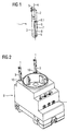
- FIG. 1 a plug-in hinge 1 is shown in a three-dimensional view, which has a pivot bearing part 2 and a plug-in bearing part 3.
- the plug-in hinge 1 is designed essentially in the form of a cone with a round cross-section and has a longitudinal axis 4.
- the pivot bearing part 2 is located at one end of the plug-in hinge 1, which is offset from the round cross-section of the pin and instead has a square cross-section. Subsequently, the square on a cranked to the longitudinal axis 4 C-shaped bearing bracket 5.
- the plug-in bearing part 3 is arranged at the one end opposite the other end of the plug-in hinge 1, the plug-in bearing part 3 is arranged.
- the plug-in bearing part 3 is provided with walls 6 which enclose a recess 7.
- a locking means 8 is mounted within the recess.
- the locking means 8 is made thin-walled and has an S-shape, whereby a resilient effect is given.
- the wall thickness is for example 0.5 mm to 3 mm.
- a free end 8.1 of the locking means 8 protrudes from the recess 7 out.
- the latching means 8 is therefore designed as a return-resistant abutment in the sense of a compensating element for compensating a force acting on the rotary bearing part 2 and / or plug-in bearing part 3 actuating force.
- the plug-in hinge 1 is as well as the locking means 8 is preferably made of plastic;
- the locking means 8 can be produced in a simple manner by the so-called injection molding process.
- Other materials, such as metals, may also be provided, since in particular the locking means 8 in the form of a metal strip has elastic or resilient properties.
- FIG. 2 a critiqueneinbau connector 9 is shown, which is provided with two hinges 1.
- the two hinges 1 are each introduced at its plug-in bearing part 3 in an opening 10 provided for this purpose in the housing of the modular socket 9.
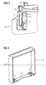
- the plug-in hinges 1 are already in their final assembly position in the housing of the row plug socket 9.
- the housing of the row plug socket 9 is shown cut open for the purpose of illustration in the region of the front plug-in hinge. It can be seen how the protruding from the recess 8 of the plug-in bearing part 3 free end 8.1 of the locking means 8 locked after complete insertion of the plug-in bearing part 3 in the housing opening 10 on a housing projection 11.
- the latching means 8 designed as an S-shaped spring element would yield and allow an upward stroke of the plug-in hinge 1 under spring pressure.
- FIG. 4 a pivot cover 12 is shown which is provided with a frame 13 and arranged thereon bearing pin 14.
- the bearing pins 14 are in this case on the pivot cover frame 13 in relation to the position of the associated lid longitudinal edge 15 is approximately parallel and with respect to the height of the pivot cover frame 13 is arranged approximately centrally.
- the pivot cover 12 is shown in its mounting position, wherein its two bearing pins are engaged on the two plug-in hinges 1 and thus stored. Due to the C-shaped bearing brackets 5 according to FIG. 1 can also be retrofitted with built-in appliances with swivel covers in a simple way.
- the modular socket 9 is shown with fully mounted on two hinges hinged lid 12, wherein the pivot cover 12 is in its closed position 16.
- the pivot cover 12 is shown in dashed lines in an intermediate position 17, wherein the two movement arrows 18, the pivoting range of the pivot cover 12 play.
- the open position 19 can be reached even at a 90 ° with respect to the closed position 16 moving pivot cover 12.
- a pivot angle of 180 ° is also possible to achieve the open position 19. If a tensile force acts on the closed pivot cover 12, the two hinges feather the force effect. If, on the other hand, a compressive force is exerted on the open pivot cover 12, then it can disengage its bearing journal from the bearing clips.
- the present invention relates to a hinge 1, which is protected against mechanical overstress or by means of the damage to attachments 12 disposed thereon are avoidable;
- the plug hinge 1 on the one hand a rotary bearing part 2 and on the other hand, a plug bearing part 3 and is provided with a plurality of walls 6, which surrounds a recess 7 in the plug-in bearing part 3 for receiving a locking means 8, wherein the locking means 8 in the sense of a compensating element to compensate for the rotary bearing part 2 and / or force acting on the plug-in bearing part 3 is executed.
Landscapes
- Engineering & Computer Science (AREA)
- Architecture (AREA)
- Civil Engineering (AREA)
- Structural Engineering (AREA)
- Connector Housings Or Holding Contact Members (AREA)
- Pivots And Pivotal Connections (AREA)
- Air Bags (AREA)
Description
- Die Erfindung betrifft ein Steckscharnier gemäß dem Oberbegriff des Patentanspruchs 1, das einerseits mit einem Drehlagerteil und anderseits mit einem Stecklagerteil versehen ist und mehrere Wandungen aufweist, die eine Aussparung in dem Stecklagerteil umgeben, welche zur Aufnahme eines Rastmittels vorgesehen ist; ein derartiges Steckscharnier ist aus der
DE 196 25 187 A1 bekannt. - Verwendung findet ein solches Steckscharnier beispielsweise in einem Reiheneinbaugerät, insbesondere in einer Reiheneinbausteckdose gemäß der
DE 20 2004 004 505 U1 , bei dem ein Schwenkdeckel zur Abdeckung bestimmter Geräteteile über das Steckscharnier mit dem Gerät verbunden ist. - Das aus der
DE 196 25 187 A1 bekannte Steckscharnier ist jedoch mit einer feststehenden und gehäuseseitig angeordneten Rastnase an dem Gehäuse arretiert, wodurch eine starre Fixierung des Steckscharniers gegeben ist. Der an dem Steckscharnier angeordnete Schwenkdeckel kann in Folge dessen bei einer unsachgemäßen Bedienung, beispielsweise bei einer Schwenkbewegung über den zulässigen Schwenkbereich hinaus, beschädigt werden. Gegebenenfalls kann dabei auch das Steckscharnier in Mitleidenschaft gezogen werden. - Der Erfindung liegt die Aufgabe zugrunde, ein Steckscharnier zu schaffen, mit dem bei mechanischer Überbeanspruchung Beschädigungen am Steckscharnier selbst und/oder an Anbauteilen vermieden werden können.
- Die Lösung der Aufgabe ist ausgehend von einem Steckscharnier gemäß dem Oberbegriff des Patentanspruchs 1 erfindungsgemäß durch die kennzeichnenden Merkmale des Patentanspruchs 1 gegeben; vorteilhafte Ausgestaltungen sind jeweils Gegenstand von weiteren Ansprüchen.
- Durch das im Sinne eines Ausgleichselements ausgeführte Rastmittel, das zur Kompensation einer auf das Drehlagerteil und/oder Stecklagerteil einwirkenden Betätigungskraft dient, wird ein Steckscharnier bereitgestellt, mit dem bei mechanischer Überbeanspruchung Beschädigungen am Schwenkdeckel bzw. am Steckscharnier selbst vermeidbar sind.
- Gemäß einer vorteilhaften Ausgestaltung ist das Rastmittel zumindest an einer der Wandungen des Stecklagerteils angeordnet und federnd ausgeführt, wodurch eine platzsparende Anordnung gegeben ist, mit der eine Deformierung des Steckscharniers bzw. des Schwenkdeckels bei erhöhter mechanischer Belastung vermieden werden kann.
- Mit Vorteil weist das Steckscharnier eine Zapfen-Bauform auf, welche bauartbedingt ein einfaches Einführen des Steckscharniers in eine dafür vorgesehene Einführöffnung an einem Gerätegehäuse ermöglicht.
- In einer weiteren vorteilhaften Ausgestaltung weist das Drehlagerteil eine C-Form auf, wodurch eine radiale Öffnung zum montagefreundlichen Einrasten bzw. zum aufwandsreduzierten Ausrasten eines Lagerbolzen des Schwenkdeckels gegeben ist. Aufwändige Verbindungselemente, wie Schrauben oder dergleichen, können somit entfallen.
- Vorteilhafterweise ist das C-förmige Drehlagerteil in Bezug zu der Längsachse des Zapfens gekröpft, so dass bei einer übermäßig starken mechanischen Belastung des Drehlagers in öffnungsrichtung der darin geführte Lagerbolzen ausrasten kann, um Bauteilschäden zu vermeiden.
- Mit Vorteil weist das Steckscharnier ein S-förmiges Federelement als Rastmittel auf, dessen festes Ende an der Bodenwandung des Stecklagerteils angeordnet ist und dessen freies Ende über die Projektionsfläche des Zapfens herausragt. Hierdurch ist ein einfaches, jedoch wirkungsvolles Rastmittel gegeben, welches in eingebautem Zustand bei auftretenden Zugkräften eine Ausgleichsbewegung zulässt und dennoch selbsttätig in seine Ausgangslage zurückkehrt.
- Vorteilhafterweise ist das Federelement als an dem Steckscharnier angespritztes Kunststoffteil ausgeführt, wodurch eine einfache Herstellung gewährleistet ist.
- Mit Vorteil weist der Schwenkdeckel zwei Lagerbolzen auf, die am Schwenkdeckelrahmen in Bezug auf die Lage der zugehörigen Deckellängskante in etwa parallel und in Bezug auf die Höhe des Schwenkdeckelrahmens in etwa mittig angeordnet sind, so dass sich ein Schwenkbereich von 180° ergibt.
- Vorteilhafterweise ist ein Einbaugerät mit dem über zwei Steckscharniere gekoppelten Schwenkdeckel ausrüstbar, wobei sich durch die in das Gehäuse des Einbaugeräts integrierbaren Steckscharniere eine insgesamt kompakte Bauform erzielen lässt, die keinen weiteren Einbauraum benötigt. Das Einbaugerät erlaubt darüber hinaus eine effiziente Montage.
- Die Erfindung sowie vorteilhafte Ausgestaltungen gemäß den Merkmalen der weiteren Ansprüche werden im Folgenden anhand in der Zeichnung dargestellter Ausführungsbeispiele näher erläutert, ohne dass insoweit eine Beschränkung der Erfindung erfolgt; darin zeigen:
- FIG 1
- ein erfindungsgemäßes Steckscharnier in einer per- spektivischen Darstellung;
- FIG 2
- eine Reiheneinbausteckdose mit eingesetzten Steck- scharnieren gemäß
FIG 1 in einer perspektivischen Darstellung; - FIG 3
- eine Schnittdarstellung der Reiheneinbausteckdose ge- mäß
FIG 2 ; - FIG 4
- einen Schwenkdeckel in einer perspektivischen Dar- stellung;
- FIG 5
- die Reiheneinbausteckdose mit einem angebauten Schwenkdeckel nach
FIG 4 ; und - FIG 6
- die Reiheneinbausteckdose gemäß
FIG 5 mit verschiede- nen Schwenkdeckelstellungen. - In
FIG 1 ist ein Steckscharnier 1 in einer räumlichen Darstellung gezeigt, das ein Drehlagerteil 2 und ein Stecklagerteil 3 aufweist. Das Steckscharnier 1 ist im Wesentlichen zapfenförmig mit einem runden Querschnitt ausgeführt und weist eine Längsachse 4 auf. Das Drehlagerteil 2 befindet sich an einem Ende des Steckscharniers 1, das von dem runden Querschnitt des Zapfens abgesetzt ist und stattdessen einen Vierkant-Querschnitt aufweist. Daran anschließend weist der Vierkant eine zu der Längsachse 4 abgekröpfte C-förmige Lagerklammer 5 auf. - An dem dem einen Ende gegenüberliegenden anderen Ende des Steckscharniers 1 ist das Stecklagerteil 3 angeordnet. Das Stecklagerteil 3 ist mit Wandungen 6 versehen, die eine Aussparung 7 einfassen. An der dem anderen Ende naheliegendsten Wandung 6 ist innerhalb der Aussparung 7 ein Rastmittel 8 angebracht. Das Rastmittel 8 ist dünnwandig ausgeführt und weist eine S-Form auf, wodurch eine federnde Wirkung gegeben ist. Die Wandungsstärke beträgt beispielsweise 0,5 mm bis 3 mm. Ein Freiende 8.1 des Rastmittels 8 ragt aus der Aussparung 7 heraus. Das Rastmittel 8 ist demzufolge als rückstellfestes Widerlager im Sinne eines Ausgleichselements zur Kompensation einer auf das Drehlagerteil 2 und/oder Stecklagerteil 3 einwirkenden Betätigungskraft ausgeführt.
- Das Steckscharnier 1 besteht ebenso wie das Rastmittel 8 vorzugsweise aus Kunststoff; in dieser Materialausführung kann das Rastmittel 8 auf einfache Weise durch das so genannte Spritzgussverfahren hergestellt werden. Andere Materialien, wie beispielsweise Metalle, können ebenfalls vorgesehen werden, da insbesondere das Rastmittel 8 in Form eines Metallstreifens elastische bzw. federnde Eigenschaften aufweist.
- In
FIG 2 ist eine Reiheneinbausteckdose 9 gezeigt, die mit zwei Steckscharnieren 1 versehen ist. Die beiden Steckscharniere 1 sind jeweils an ihrem Stecklagerteil 3 in einer dafür vorgesehenen Öffnung 10 in dem Gehäuse der Reiheneinbausteckdose 9 ansatzweise eingeführt. - Gemäß
FIG 3 befinden sich die Steckscharniere 1 bereits in ihrer Montageendstellung in dem Gehäuse der Reiheneinbausteckdose 9. Das Gehäuse der Reiheneinbausteckdose 9 ist zur Veranschaulichung im Bereich des vorderen Steckscharniers aufgeschnitten dargestellt. Dabei ist ersichtlich, wie das aus der Aussparung 8 des Stecklagerteils 3 herausragende Freiende 8.1 des Rastmittels 8 nach vollständiger Einführung des Stecklagerteils 3 in der Gehäuseöffnung 10 an einem Gehäusevorsprung 11 verrastet. Bei einer Krafteinwirkung auf das Steckscharnier 1 entgegen der Einführrichtung würde demzufolge das als S-förmiges Federelement ausgeführte Rastmittel 8 nachgeben und einen Aufwärtshub des Steckscharniers 1 unter Federdruck zulassen. - In
FIG 4 ist ein Schwenkdeckel 12 gezeigt, der mit einem Rahmen 13 und daran angeordneten Lagerbolzen 14 versehen ist. Die Lagerbolzen 14 sind hierbei am Schwenkdeckelrahmen 13 in Bezug auf die Lage der zugehörigen Deckellängskante 15 in etwa parallel und in Bezug auf die Höhe des Schwenkdeckelrahmens 13 in etwa mittig angeordnet ist. - Gemäß
FIG 5 ist der Schwenkdeckel 12 in seiner Montagestellung gezeigt, wobei seine beiden Lagerbolzen an den beiden Steckscharnieren 1 eingerastet und somit gelagert sind. Bedingt durch die C-förmigen Lagerklammern 5 gemäßFIG 1 kann auch eine Nachrüstung von Einbaugeräten mit Schwenkdeckeln auf einfache Weise erfolgen. - In
FIG 6 ist die Reiheneinbausteckdose 9 mit vollständig über zwei Steckscharniere montiertem Schwenkdeckel 12 gezeigt, wobei sich der Schwenkdeckel 12 in seiner Schließstellung 16 befindet. Beispielhaft ist der Schwenkdeckel 12 in einer Zwischenstellung 17 auch strichliert dargestellt, wobei die beiden Bewegungspfeile 18 den Schwenkbereich des Schwenkdeckels 12 wiedergeben. Die Öffnungsstellung 19 ist bereits bei einem um 90° in Bezug auf die Schließstellung 16 bewegten Schwenkdeckel 12 erreichbar. Ein Verschwenkwinkel von 180° ist gleichfalls zur Erreichung der Öffnungsstellung 19 möglich. Sofern eine Zugkraft auf den geschlossenen Schwenkdeckel 12 einwirkt, federn die beiden Steckscharniere die Kraftwirkung ab. Wird hingegen eine Druckkraft auf den geöffneten Schwenkdeckel 12 ausgeübt, so kann dieser an seinen Lagerzapfen aus den Lagerklammern ausrasten. In beiden Extremfällen kann somit eine Beschädigung oder Deformierung der Steckscharniere bzw. des Schwenkdeckels sicher vermieden werden. Sofern der Einsatz eines deckellosen Einbaugerätes gewünscht sein sollte, kann dieser zusammen mit den Steckscharnieren demontiert werden, und zwar ohne dass störende Gehäuse- oder Lagerkonturen stehen bleiben. Dabei besteht beispielsweise die Möglichkeit, über eine Entriegelungsöffnung mit einem Entriegelungsmittel das Freiende 8.1 bzw. das Rastmittel 8 so zurückzustellen, dass das Steckscharnier 1 abgezogen werden kann. - Zusammenfassend bezieht sich die vorliegende Erfindung auf ein Steckscharnier 1, das vor mechanischer Überbeanspruchung geschützt ist bzw. mittels dem Beschädigungen an daran angeordneten Anbauteilen 12 vermeidbar sind; hierbei weist das Steckscharnier 1 einerseits ein Drehlagerteil 2 und anderseits ein Stecklagerteil 3 auf und ist mit mehreren Wandungen 6 versehen, die eine Aussparung 7 in dem Stecklagerteil 3 zur Aufnahme eines Rastmittels 8 umgeben, wobei das Rastmittel 8 im Sinne eines Ausgleichselements zur Kompensation einer auf das Drehlagerteil 2 und/oder auf das Stecklagerteil 3 einwirkenden Kraft ausgeführt ist.
Claims (11)
- Steckscharnier (1), das einerseits mit einem Drehlagerteil (2) und anderseits mit einem Stecklagerteil (3) versehen ist und mehrere Wandungen (6) aufweist, die eine Aussparung (7) in dem Stecklagerteil (3) zur Aufnahme eines Rastmittels (8) umgeben, dadurch gekennzeichnet, dass das Rastmittel (8) im Sinne eines Ausgleichselements zur Kompensation einer auf das Drehlagerteil (2) und/oder Stecklagerteil (3) einwirkenden Betätigungskraft ausgeführt ist.
- Steckscharnier nach Anspruch 1, bei dem das Rastmittel (8) zumindest an einer der Wandungen (6) angeordnet und federnd ausgeführt ist.
- Steckscharnier nach Anspruch 1 oder 2, mit einer Zapfen-Bauform.
- Steckscharnier nach Anspruch 1,2 oder 3, bei dem das Drehlagerteil C-förmig ausgebildet ist.
- Steckscharnier nach einem der Ansprüche 1 bis 4, bei dem das C-förmige Drehlagerteil (5) versetzt, insbesondere im rechten Winkel, zu der Längsachse (4) des Zapfens angeordnet ist.
- Steckscharnier nach einem der vorhergehenden Ansprüche, mit einem S-förmigen Federelement als Rastmittel (8), dessen festes Ende an der Bodenwandung (6) angeordnet ist und dessen freies Ende über die Projektionsfläche des Zapfens herausragt.
- Steckscharnier nach Anspruch 6, bei dem das Federelement als angespritztes Kunststoffteil ausgeführt ist.
- Schwenkdeckel mit zumindest einem Steckscharnier nach einem der Ansprüche 1 bis 7.
- Schwenkdeckel (12) nach Anspruch 8, dessen Lagerbolzen (14) am Schwenkdeckelrahmen (13) in Bezug auf die Lage der zugehörigen Deckellängskante (15) in etwa parallel und in Bezug auf die Höhe des Schwenkdeckelrahmens (13) in etwa mittig angeordnet ist.
- Einbaugerät (9) mit einem Schwenkdeckel (12) nach einem der Ansprüche 8 oder 9.
- Einbaugerät (9) nach Anspruch 10, das als Reiheneinbausteckdose ausgeführt ist.
Applications Claiming Priority (2)
| Application Number | Priority Date | Filing Date | Title |
|---|---|---|---|
| DE102005026715A DE102005026715B3 (de) | 2005-06-09 | 2005-06-09 | Steckscharnier |
| PCT/EP2006/062708 WO2006131458A1 (de) | 2005-06-09 | 2006-05-30 | Steckscharnier |
Publications (2)
| Publication Number | Publication Date |
|---|---|
| EP1889333A1 EP1889333A1 (de) | 2008-02-20 |
| EP1889333B1 true EP1889333B1 (de) | 2010-07-14 |
Family
ID=36890967
Family Applications (1)
| Application Number | Title | Priority Date | Filing Date |
|---|---|---|---|
| EP06763361A Not-in-force EP1889333B1 (de) | 2005-06-09 | 2006-05-30 | Steckscharnier |
Country Status (5)
| Country | Link |
|---|---|
| EP (1) | EP1889333B1 (de) |
| CN (1) | CN101180770B (de) |
| AT (1) | ATE474346T1 (de) |
| DE (2) | DE102005026715B3 (de) |
| WO (1) | WO2006131458A1 (de) |
Families Citing this family (4)
| Publication number | Priority date | Publication date | Assignee | Title |
|---|---|---|---|---|
| DE102012102188B4 (de) * | 2012-03-15 | 2017-07-27 | Phoenix Contact Gmbh & Co. Kg | Steckverbinder und Verfahren zur Montage eines Steckverbinders |
| DE102014107828B4 (de) * | 2014-06-04 | 2024-04-11 | Albrecht Jung Gmbh & Co. Kg | Klappdeckel |
| CN111926533B (zh) * | 2019-05-13 | 2025-04-15 | 青岛海尔洗衣机有限公司 | 盖组件、衣物处理筒和顶开式衣物处理设备 |
| DE102021120428A1 (de) | 2021-08-05 | 2023-02-09 | Endress+Hauser Conducta Gmbh+Co. Kg | Flügelscharnier für ein Feldgerätgehäuse sowie Feldgerätgehäuse mit Flügelscharnier |
Family Cites Families (7)
| Publication number | Priority date | Publication date | Assignee | Title |
|---|---|---|---|---|
| US3055015A (en) * | 1960-07-25 | 1962-09-25 | Melvin H Silverman | Releasable hinge assembly |
| DE3932128C1 (de) * | 1989-09-27 | 1990-11-29 | Ford-Werke Ag, 5000 Koeln, De | |
| DE4214031C2 (de) * | 1992-04-29 | 1997-09-04 | Berker Geb | Scharniergelenk an einem Steckdosenklappdeckel |
| DE4407652C2 (de) * | 1994-03-08 | 2002-09-19 | Berker Geb | Steckdosenabdeckung |
| SE9502383L (sv) * | 1995-06-30 | 1996-11-25 | Thorsman & Co Ab | Gångjärnsarrangemang för en golvmonterad uttagsbox |
| DE19949779C2 (de) * | 1999-10-15 | 2002-08-01 | Samson Ag | Scharnier |
| DE202004004505U1 (de) * | 2004-03-23 | 2004-09-09 | Komos Gmbh Komponenten Module Systeme | Oberflächenbündige Einbausteckdose |
-
2005
- 2005-06-09 DE DE102005026715A patent/DE102005026715B3/de not_active Expired - Fee Related
-
2006
- 2006-05-30 CN CN2006800181176A patent/CN101180770B/zh not_active Expired - Fee Related
- 2006-05-30 WO PCT/EP2006/062708 patent/WO2006131458A1/de not_active Ceased
- 2006-05-30 EP EP06763361A patent/EP1889333B1/de not_active Not-in-force
- 2006-05-30 AT AT06763361T patent/ATE474346T1/de active
- 2006-05-30 DE DE502006007428T patent/DE502006007428D1/de active Active
Also Published As
| Publication number | Publication date |
|---|---|
| CN101180770A (zh) | 2008-05-14 |
| CN101180770B (zh) | 2011-09-07 |
| DE502006007428D1 (de) | 2010-08-26 |
| DE102005026715B3 (de) | 2006-09-28 |
| WO2006131458A1 (de) | 2006-12-14 |
| ATE474346T1 (de) | 2010-07-15 |
| EP1889333A1 (de) | 2008-02-20 |
Similar Documents
| Publication | Publication Date | Title |
|---|---|---|
| EP3969706B1 (de) | Möbelantrieb | |
| EP2796650B1 (de) | Möbelscharnier | |
| EP2729037B1 (de) | Schublade | |
| EP3969705B1 (de) | Möbelbeschlag | |
| DE102015106917B4 (de) | Möbelscharnier mit einem Dämpfer und einer Feder | |
| DE29610947U1 (de) | Kabelkanalprofil | |
| WO2013029067A1 (de) | Schublade | |
| EP3745920B1 (de) | Zarge für einen schubkasten | |
| EP3277899B1 (de) | Türgriffanordnung für ein kraftfahrzeug | |
| DE2828052A1 (de) | Schnaepperscharnier | |
| DE102009031686B4 (de) | Schubladenfront mit Verschließmechanismus zum Verriegeln von Schubladen in Fahrzeugen | |
| DE102005026715B3 (de) | Steckscharnier | |
| DE102009018781B4 (de) | Verbindungsbaugruppe | |
| DE102014107406A1 (de) | Türgriffanordnung für ein Kraftfahrzeug | |
| EP2014847B2 (de) | Revisionsabdeckung | |
| DE2541144A1 (de) | Schnaepperscharnier | |
| EP2300677A1 (de) | Scharniertopf für möbelscharniere | |
| DE29602613U1 (de) | Vorrichtung zum druckfesten Dichten einer Tür | |
| DE102006009941B4 (de) | In ein Kraftfahrzeug einbaubarer Aschenbecher | |
| DE10313842B4 (de) | Schranktür | |
| DE102008031245A1 (de) | Haushaltsgerät, insbesondere Einbaubackofen | |
| DE102009017029C5 (de) | Bandaufnahme für Stahlzargen | |
| EP1752666B1 (de) | Lager- und Halteeinrichtung zur Aufnahme und Lagerung eines Lagerbolzens einer Lagerwelle | |
| DE29802458U1 (de) | Türaufhängevorrichtung für stumpf angeschlagene Türen mit Holzzargen | |
| EP1876319B1 (de) | Gleitfuehrung fuer Schiebefluegel oder Abstellschiebefluegel |
Legal Events
| Date | Code | Title | Description |
|---|---|---|---|
| PUAI | Public reference made under article 153(3) epc to a published international application that has entered the european phase |
Free format text: ORIGINAL CODE: 0009012 |
|
| 17P | Request for examination filed |
Effective date: 20071004 |
|
| AK | Designated contracting states |
Kind code of ref document: A1 Designated state(s): AT BE BG CH CY CZ DE DK EE ES FI FR GB GR HU IE IS IT LI LT LU LV MC NL PL PT RO SE SI SK TR |
|
| DAX | Request for extension of the european patent (deleted) | ||
| GRAP | Despatch of communication of intention to grant a patent |
Free format text: ORIGINAL CODE: EPIDOSNIGR1 |
|
| GRAS | Grant fee paid |
Free format text: ORIGINAL CODE: EPIDOSNIGR3 |
|
| GRAA | (expected) grant |
Free format text: ORIGINAL CODE: 0009210 |
|
| AK | Designated contracting states |
Kind code of ref document: B1 Designated state(s): AT BE BG CH CY CZ DE DK EE ES FI FR GB GR HU IE IS IT LI LT LU LV MC NL PL PT RO SE SI SK TR |
|
| REG | Reference to a national code |
Ref country code: GB Ref legal event code: FG4D Free format text: NOT ENGLISH |
|
| REG | Reference to a national code |
Ref country code: CH Ref legal event code: EP |
|
| REG | Reference to a national code |
Ref country code: IE Ref legal event code: FG4D |
|
| REF | Corresponds to: |
Ref document number: 502006007428 Country of ref document: DE Date of ref document: 20100826 Kind code of ref document: P |
|
| REG | Reference to a national code |
Ref country code: NL Ref legal event code: VDEP Effective date: 20100714 |
|
| LTIE | Lt: invalidation of european patent or patent extension |
Effective date: 20100714 |
|
| PG25 | Lapsed in a contracting state [announced via postgrant information from national office to epo] |
Ref country code: LT Free format text: LAPSE BECAUSE OF FAILURE TO SUBMIT A TRANSLATION OF THE DESCRIPTION OR TO PAY THE FEE WITHIN THE PRESCRIBED TIME-LIMIT Effective date: 20100714 Ref country code: NL Free format text: LAPSE BECAUSE OF FAILURE TO SUBMIT A TRANSLATION OF THE DESCRIPTION OR TO PAY THE FEE WITHIN THE PRESCRIBED TIME-LIMIT Effective date: 20100714 Ref country code: FI Free format text: LAPSE BECAUSE OF FAILURE TO SUBMIT A TRANSLATION OF THE DESCRIPTION OR TO PAY THE FEE WITHIN THE PRESCRIBED TIME-LIMIT Effective date: 20100714 |
|
| REG | Reference to a national code |
Ref country code: IE Ref legal event code: FD4D |
|
| PG25 | Lapsed in a contracting state [announced via postgrant information from national office to epo] |
Ref country code: PT Free format text: LAPSE BECAUSE OF FAILURE TO SUBMIT A TRANSLATION OF THE DESCRIPTION OR TO PAY THE FEE WITHIN THE PRESCRIBED TIME-LIMIT Effective date: 20101115 Ref country code: PL Free format text: LAPSE BECAUSE OF FAILURE TO SUBMIT A TRANSLATION OF THE DESCRIPTION OR TO PAY THE FEE WITHIN THE PRESCRIBED TIME-LIMIT Effective date: 20100714 Ref country code: IS Free format text: LAPSE BECAUSE OF FAILURE TO SUBMIT A TRANSLATION OF THE DESCRIPTION OR TO PAY THE FEE WITHIN THE PRESCRIBED TIME-LIMIT Effective date: 20101114 Ref country code: CY Free format text: LAPSE BECAUSE OF FAILURE TO SUBMIT A TRANSLATION OF THE DESCRIPTION OR TO PAY THE FEE WITHIN THE PRESCRIBED TIME-LIMIT Effective date: 20100714 Ref country code: BG Free format text: LAPSE BECAUSE OF FAILURE TO SUBMIT A TRANSLATION OF THE DESCRIPTION OR TO PAY THE FEE WITHIN THE PRESCRIBED TIME-LIMIT Effective date: 20101014 Ref country code: SI Free format text: LAPSE BECAUSE OF FAILURE TO SUBMIT A TRANSLATION OF THE DESCRIPTION OR TO PAY THE FEE WITHIN THE PRESCRIBED TIME-LIMIT Effective date: 20100714 |
|
| PG25 | Lapsed in a contracting state [announced via postgrant information from national office to epo] |
Ref country code: SE Free format text: LAPSE BECAUSE OF FAILURE TO SUBMIT A TRANSLATION OF THE DESCRIPTION OR TO PAY THE FEE WITHIN THE PRESCRIBED TIME-LIMIT Effective date: 20100714 Ref country code: GR Free format text: LAPSE BECAUSE OF FAILURE TO SUBMIT A TRANSLATION OF THE DESCRIPTION OR TO PAY THE FEE WITHIN THE PRESCRIBED TIME-LIMIT Effective date: 20101015 Ref country code: LV Free format text: LAPSE BECAUSE OF FAILURE TO SUBMIT A TRANSLATION OF THE DESCRIPTION OR TO PAY THE FEE WITHIN THE PRESCRIBED TIME-LIMIT Effective date: 20100714 |
|
| PG25 | Lapsed in a contracting state [announced via postgrant information from national office to epo] |
Ref country code: DK Free format text: LAPSE BECAUSE OF FAILURE TO SUBMIT A TRANSLATION OF THE DESCRIPTION OR TO PAY THE FEE WITHIN THE PRESCRIBED TIME-LIMIT Effective date: 20100714 Ref country code: IE Free format text: LAPSE BECAUSE OF FAILURE TO SUBMIT A TRANSLATION OF THE DESCRIPTION OR TO PAY THE FEE WITHIN THE PRESCRIBED TIME-LIMIT Effective date: 20100714 |
|
| PLBE | No opposition filed within time limit |
Free format text: ORIGINAL CODE: 0009261 |
|
| STAA | Information on the status of an ep patent application or granted ep patent |
Free format text: STATUS: NO OPPOSITION FILED WITHIN TIME LIMIT |
|
| PG25 | Lapsed in a contracting state [announced via postgrant information from national office to epo] |
Ref country code: RO Free format text: LAPSE BECAUSE OF FAILURE TO SUBMIT A TRANSLATION OF THE DESCRIPTION OR TO PAY THE FEE WITHIN THE PRESCRIBED TIME-LIMIT Effective date: 20100714 Ref country code: CZ Free format text: LAPSE BECAUSE OF FAILURE TO SUBMIT A TRANSLATION OF THE DESCRIPTION OR TO PAY THE FEE WITHIN THE PRESCRIBED TIME-LIMIT Effective date: 20100714 Ref country code: EE Free format text: LAPSE BECAUSE OF FAILURE TO SUBMIT A TRANSLATION OF THE DESCRIPTION OR TO PAY THE FEE WITHIN THE PRESCRIBED TIME-LIMIT Effective date: 20100714 Ref country code: SK Free format text: LAPSE BECAUSE OF FAILURE TO SUBMIT A TRANSLATION OF THE DESCRIPTION OR TO PAY THE FEE WITHIN THE PRESCRIBED TIME-LIMIT Effective date: 20100714 |
|
| 26N | No opposition filed |
Effective date: 20110415 |
|
| PG25 | Lapsed in a contracting state [announced via postgrant information from national office to epo] |
Ref country code: ES Free format text: LAPSE BECAUSE OF FAILURE TO SUBMIT A TRANSLATION OF THE DESCRIPTION OR TO PAY THE FEE WITHIN THE PRESCRIBED TIME-LIMIT Effective date: 20101025 |
|
| REG | Reference to a national code |
Ref country code: DE Ref legal event code: R097 Ref document number: 502006007428 Country of ref document: DE Effective date: 20110415 |
|
| BERE | Be: lapsed |
Owner name: SIEMENS A.G. Effective date: 20110531 |
|
| PG25 | Lapsed in a contracting state [announced via postgrant information from national office to epo] |
Ref country code: MC Free format text: LAPSE BECAUSE OF NON-PAYMENT OF DUE FEES Effective date: 20110531 |
|
| REG | Reference to a national code |
Ref country code: CH Ref legal event code: PL |
|
| GBPC | Gb: european patent ceased through non-payment of renewal fee |
Effective date: 20110530 |
|
| PG25 | Lapsed in a contracting state [announced via postgrant information from national office to epo] |
Ref country code: CH Free format text: LAPSE BECAUSE OF NON-PAYMENT OF DUE FEES Effective date: 20110531 Ref country code: LI Free format text: LAPSE BECAUSE OF NON-PAYMENT OF DUE FEES Effective date: 20110531 |
|
| PG25 | Lapsed in a contracting state [announced via postgrant information from national office to epo] |
Ref country code: BE Free format text: LAPSE BECAUSE OF NON-PAYMENT OF DUE FEES Effective date: 20110531 |
|
| PG25 | Lapsed in a contracting state [announced via postgrant information from national office to epo] |
Ref country code: GB Free format text: LAPSE BECAUSE OF NON-PAYMENT OF DUE FEES Effective date: 20110530 |
|
| REG | Reference to a national code |
Ref country code: AT Ref legal event code: MM01 Ref document number: 474346 Country of ref document: AT Kind code of ref document: T Effective date: 20110530 |
|
| PG25 | Lapsed in a contracting state [announced via postgrant information from national office to epo] |
Ref country code: AT Free format text: LAPSE BECAUSE OF NON-PAYMENT OF DUE FEES Effective date: 20110530 |
|
| PG25 | Lapsed in a contracting state [announced via postgrant information from national office to epo] |
Ref country code: LU Free format text: LAPSE BECAUSE OF NON-PAYMENT OF DUE FEES Effective date: 20110530 |
|
| PG25 | Lapsed in a contracting state [announced via postgrant information from national office to epo] |
Ref country code: TR Free format text: LAPSE BECAUSE OF FAILURE TO SUBMIT A TRANSLATION OF THE DESCRIPTION OR TO PAY THE FEE WITHIN THE PRESCRIBED TIME-LIMIT Effective date: 20100714 |
|
| PG25 | Lapsed in a contracting state [announced via postgrant information from national office to epo] |
Ref country code: HU Free format text: LAPSE BECAUSE OF FAILURE TO SUBMIT A TRANSLATION OF THE DESCRIPTION OR TO PAY THE FEE WITHIN THE PRESCRIBED TIME-LIMIT Effective date: 20100714 |
|
| PGFP | Annual fee paid to national office [announced via postgrant information from national office to epo] |
Ref country code: FR Payment date: 20140513 Year of fee payment: 9 Ref country code: IT Payment date: 20140527 Year of fee payment: 9 |
|
| PGFP | Annual fee paid to national office [announced via postgrant information from national office to epo] |
Ref country code: DE Payment date: 20140718 Year of fee payment: 9 |
|
| REG | Reference to a national code |
Ref country code: DE Ref legal event code: R119 Ref document number: 502006007428 Country of ref document: DE |
|
| PG25 | Lapsed in a contracting state [announced via postgrant information from national office to epo] |
Ref country code: IT Free format text: LAPSE BECAUSE OF NON-PAYMENT OF DUE FEES Effective date: 20150530 |
|
| REG | Reference to a national code |
Ref country code: FR Ref legal event code: ST Effective date: 20160129 |
|
| PG25 | Lapsed in a contracting state [announced via postgrant information from national office to epo] |
Ref country code: DE Free format text: LAPSE BECAUSE OF NON-PAYMENT OF DUE FEES Effective date: 20151201 |
|
| PG25 | Lapsed in a contracting state [announced via postgrant information from national office to epo] |
Ref country code: FR Free format text: LAPSE BECAUSE OF NON-PAYMENT OF DUE FEES Effective date: 20150601 |