EP1888910B1 - A fuel-heating assembly and method for the pre-heating of fuel of an internal combustion engine - Google Patents
A fuel-heating assembly and method for the pre-heating of fuel of an internal combustion engine Download PDFInfo
- Publication number
- EP1888910B1 EP1888910B1 EP06741337A EP06741337A EP1888910B1 EP 1888910 B1 EP1888910 B1 EP 1888910B1 EP 06741337 A EP06741337 A EP 06741337A EP 06741337 A EP06741337 A EP 06741337A EP 1888910 B1 EP1888910 B1 EP 1888910B1
- Authority
- EP
- European Patent Office
- Prior art keywords
- fuel
- fact
- heating
- heating assembly
- assembly according
- Prior art date
- Legal status (The legal status is an assumption and is not a legal conclusion. Google has not performed a legal analysis and makes no representation as to the accuracy of the status listed.)
- Active
Links
Images








Classifications
-
- F—MECHANICAL ENGINEERING; LIGHTING; HEATING; WEAPONS; BLASTING
- F02—COMBUSTION ENGINES; HOT-GAS OR COMBUSTION-PRODUCT ENGINE PLANTS
- F02M—SUPPLYING COMBUSTION ENGINES IN GENERAL WITH COMBUSTIBLE MIXTURES OR CONSTITUENTS THEREOF
- F02M55/00—Fuel-injection apparatus characterised by their fuel conduits or their venting means; Arrangements of conduits between fuel tank and pump F02M37/00
- F02M55/02—Conduits between injection pumps and injectors, e.g. conduits between pump and common-rail or conduits between common-rail and injectors
- F02M55/025—Common rails
-
- F—MECHANICAL ENGINEERING; LIGHTING; HEATING; WEAPONS; BLASTING
- F02—COMBUSTION ENGINES; HOT-GAS OR COMBUSTION-PRODUCT ENGINE PLANTS
- F02M—SUPPLYING COMBUSTION ENGINES IN GENERAL WITH COMBUSTIBLE MIXTURES OR CONSTITUENTS THEREOF
- F02M53/00—Fuel-injection apparatus characterised by having heating, cooling or thermally-insulating means
- F02M53/02—Fuel-injection apparatus characterised by having heating, cooling or thermally-insulating means with fuel-heating means, e.g. for vaporising
-
- F—MECHANICAL ENGINEERING; LIGHTING; HEATING; WEAPONS; BLASTING
- F02—COMBUSTION ENGINES; HOT-GAS OR COMBUSTION-PRODUCT ENGINE PLANTS
- F02M—SUPPLYING COMBUSTION ENGINES IN GENERAL WITH COMBUSTIBLE MIXTURES OR CONSTITUENTS THEREOF
- F02M53/00—Fuel-injection apparatus characterised by having heating, cooling or thermally-insulating means
- F02M53/04—Injectors with heating, cooling, or thermally-insulating means
- F02M53/06—Injectors with heating, cooling, or thermally-insulating means with fuel-heating means, e.g. for vaporising
-
- F—MECHANICAL ENGINEERING; LIGHTING; HEATING; WEAPONS; BLASTING
- F02—COMBUSTION ENGINES; HOT-GAS OR COMBUSTION-PRODUCT ENGINE PLANTS
- F02M—SUPPLYING COMBUSTION ENGINES IN GENERAL WITH COMBUSTIBLE MIXTURES OR CONSTITUENTS THEREOF
- F02M55/00—Fuel-injection apparatus characterised by their fuel conduits or their venting means; Arrangements of conduits between fuel tank and pump F02M37/00
- F02M55/02—Conduits between injection pumps and injectors, e.g. conduits between pump and common-rail or conduits between common-rail and injectors
-
- F—MECHANICAL ENGINEERING; LIGHTING; HEATING; WEAPONS; BLASTING
- F02—COMBUSTION ENGINES; HOT-GAS OR COMBUSTION-PRODUCT ENGINE PLANTS
- F02M—SUPPLYING COMBUSTION ENGINES IN GENERAL WITH COMBUSTIBLE MIXTURES OR CONSTITUENTS THEREOF
- F02M69/00—Low-pressure fuel-injection apparatus ; Apparatus with both continuous and intermittent injection; Apparatus injecting different types of fuel
- F02M69/46—Details, component parts or accessories not provided for in, or of interest apart from, the apparatus covered by groups F02M69/02 - F02M69/44
- F02M69/462—Arrangement of fuel conduits, e.g. with valves for maintaining pressure in the pipes after the engine being shut-down
- F02M69/465—Arrangement of fuel conduits, e.g. with valves for maintaining pressure in the pipes after the engine being shut-down of fuel rails
Definitions
- the present invention refers to a fuel-heating assembly and to a method for the pre-heating of fuel for an internal combustion engine. Said assembly and method are employed mainly in engines that consume fuels with high specific heat of vaporization.
- Otto cycle internal combustion engines that use alcohol fuel, have systems and devices for aiding the cold start thereof. These engines do not, necessarily, consume only alcohol, but may also consume a blend in any proportion of alcohol and gasoline, which are commercially known as flexfuel, trifuel, dual-fuel or tri-fuel.
- the cold start system when a high percentage of alcohol, or pure alcohol, is used, the cold start system must be activated for aiding in the cold start of the engine.
- This system consists, basically, in the gasoline injection at some admission component of the engine, such as, for example, the intake manifold or the combustion chamber itself.
- gasoline is due to the fact that it has a specific heat of vaporization lower than alcohol, thus it becomes unnecessary the withdrawal of too much heat from the environment. This is what in fact prevents the alcohol vaporization, once it has a high specific heat of vaporization, so, when injected in the engine at low temperatures, it condensates.
- a second fuel compartment with a lower volume than the one of the main tank is used, this second compartment being installed, usually in the vault of the engine of a vehicle, what takes up a significant amount of room.
- Diesel oil for example, has a spontaneous ignition temperature of 250°C, temperature well below the alcohol.
- the most efficient solution is that which heats the fuel at the end of the fuel supply line, site where the fuel rail and the injection valve are found, next to the inlet of the engine cylinder. This heating, at the end of the supply line prevents the cooling of the fuel in the path through the fuel line with respective loss of efficiency of the system.
- One of those solutions is the preheating of the fuel, preferably alcohol, in the inner part of the fuel rail of the internal combustion engine.
- the heating may be performed with the introduction of heating plugs in the rail, in such a way that they heat the fuel before the start of the engine.
- One drawback of this solution is the cost of having a heating controller through a temperature sensor inside the fuel rail.
- the heating elements due to the fact that the heating elements have to heat all the fuel present at the rail, the heating takes up a significantly long time, so that the user must wait a relatively long time for the fuel to be heated.
- the user does not wait long enough for the fuel to be adequately heated, in such a way that is necessary to obtain a satisfactory start and that has reduction in the emissions of pollutants, mainly HC.
- the volume of fuel contained in the rail is relatively high for the power generated by the heating elements.
- a simple solution would be the increase of the amount of these elements, or the power thereof, but that would significantly Increase the production cost of the fuel heating assembly In the rail. And it would still require a higher capacity of the power source, that is, the battery.
- heating elements are inside an injection line that comes from a main tube of the rail, i.e. the rail per see.
- the heating element transfers heat to the fuel when the fuel flows from the rail and is passing trough the injection line in direction to an injection valve; thus, not all the amount of fuel that is in the fuel rail must be heated for providing heated fuel to the injection valve.
- the present invention refers to a fuel-heating assembly used in an internal combustion engine.
- This assembly has a fuel rail which is provided with a plurality of fuel injection valves, which provide fuel to the engine, the fuel being properly pre-heated before the injection thereof.
- This adequate fuel pre-heating is possible due to the fact that an exact amount of fuel is heated in a pre-heating region at the fuel rail.
- a method for fuel pre-heating is also disclosed in the present invention.
- the method proposes the pre-heating of fuel without a conscious intervention of the user, thus optimizing the necessary pre-heating time.
- the present invention solves the problems presented in the state of the art by means of a fuel-heating assembly.
- the assembly has an arrangement and devices which allow the cold start of an internal combustion engine using a fuel with high specific heat of vaporization without the need of an additional reservoir of starting fuel. Furthermore, it also allows lower emissions of hydrocarbons and pollutants during cold start and operation of the engine.
- the assembly for heating of this invention is shown inside a fuel rail, the devices thereof being fixed onto the fuel rail in such a way as to allow the desired fuel heating for the start of the engine, a sufficient temperature being reached for the burning of the fuel in the combustion chamber of the engine.
- This adequate volume is greater than the volume contained in the inner part of the injection valve and smaller that all the volume contained in the inner part of the rail. Thus, in case the volume of heated fuel is lower than the adequate volume, after the start the engine cannot keep up and does not operate in the correct way.
- the present invention provides the heating of an ideal volume of fuel from heating elements and other devices of the assembly.
- a fuel rail 1a has a fuel inlet 2a. From this fuel inlet 2 fuel is provided from a pressurization system, which is not disclosed in the figures.
- the pressurization system consists basically of a fuel pump that pressurizes fuel in a piping which is connected to the fuel inlet 2, which, by its turn, keeps the inner part of the rail 1 pressurized with fuel.
- each outlet 4a there is connected a respective injection valve 5a, which atomizes the fuel before it is burnt in a combustion chamber of an internal combustion engine.
- the injection valves 5a are connected to the rail 1 a by means of retention elements 6 which are, preferably, clamps 6a. These clamps 6a keep the injection valves fixed to the rail in a tight way, preventing thus the exit of pressurized fuel at the junction of the injection valve 5a with the fuel outlet 4a.
- an upper face 7 Opposed to the lower face 3 there is an upper face 7, which contains reception openings 8a of heating elements 9a.
- the openings 8a allow that each heating element 9a enters the rail 1a and heats the fuel contained therein (the heating will be further explained).
- the isolated heating element 9a can be seen, that is, not mounted onto the borehole 8a of the fuel rail 1.
- the heating element 9a is similar to a heating element of the state of the art, but concentrates its heat distribution in a different way, as will be further explained.
- the heating element 9a has at one of its ends a lance 12a which is responsible for the heat transfer to the fuel to be heated in the inner part of rail 1 a.
- This lance 12a is composed by an outer layer that is hot-gas and corrosion resistant. It is hot-gas resistant, once that at the inner part thereof there is a filament that transforms electric power into thermal energy, homogenously, to a compressed magnesium oxide powder. It is corrosion resistant, once that it is in direct contact with fuel, what may be highly corrosive, such as alcohol.
- a central body 13 which is responsible for the engaging of the heating element 9a to the borehole 8a of the rail 1 a, there is a sealing ring 15 that performs the sealing and prevents the leaking of fuel from the rail 1 a through the borehole 8a.
- a cable 14 that by its turn is linked to the connector 11, responsible for the electric power supply.
- the clamps 10 are connected in such a way as to keep the heating element 9a fixed to the rail 1.
- the first embodiment of the invention seen in figure 3 , is a cross-sectional view of the rail 1 a in which the sections of the injection valves 5a and of the heating element 9a are shown.
- the injection valve 5a does not show any significant change when compared to a valve of the state of the art. The most significant difference is that it does not show a filter at the fuel inlet 17, or show a modified filter between a lance 12a and an inner wall 18 of inlet 17.
- This filter is not disclosed in figure 3 , but consists basically of a filter of the state of the art with an internal borehole, being resistant to high temperatures, as it is in direct contact with the lance 12a.
- another filter can optionally be mounted in the fuel opening 2a of the rail 1a.
- the heating element 9a is found at the upper face 7 and is engaged to the opening 8a of the rail 1a. It is worthwhile to stress, as mentioned before, that the heating element is fixed by the clamp 16 and sealed by the sealing ring 15 to the opening 8a.
- the lance 12a is inserted in the inner part of the rail 1a where the fuel to be is heated is, being positioned in such a way at the rail 1a that it concentrates in a heat transfer region 19a part of the fuel of the rail around it.
- only part of the fuel that is present in the rail 1 is able to receive heat coming from the lance 12a. That is due to the fact that it is aimed only the heating of part of the fuel of the rail in such a way that it can be assured that the fuel which will enter the injection valve 5a is properly heated. That is because necessarily the fuel which will enter the injection valve 5a will have to have passed through the heat transfer region 19a.
- the lance 12a is able to have enough power to assure an injection of properly heated fuel to an internal combustion engine, which is one of the aims of the present invention.
- fins 20a are positioned next to the lance 12a in such a way as to restrict the flow of all fuel from the rail 1a to the heat transfer region 19a. That increases the required concentration. Therefore, it is thus assured that the fuel will be suitably heated.
- the fins 20a run along the extension of the inner part of the rail 1a and have a passage 21 a between the heat transfer region 19a e the remaining of the inner part of rail 1. That allows the volume of fuel present in region 19a to be adequate to be heated during the start of an internal combustion engine. It is noted that the position of fins 20a does not depend on the operation of said assembly, in such a way that the former can show other geometries, such as, for example, instead of fins 20a, it is possible to use an inner wall with holes. Later there will be described other enbodiements of the fins of the set, object of this invention, being that the essential is that the flow is restricted to the heating region 19a.
- the heat exchange area is larger than in the second embodiment, which will be further shown.
- the opening 8a it is necessary for the opening 8a to have a reference diameter to pre-position the lance 12a aiming at assuring it to be concentric in relation to the fuel inlet 17.
- This reference diameter has a hole with controlled dimension so that, during the mounting of the assembly, the lance 12a is with interference, allowing thus a fixation without clearance.
- the second embodiment of the invention can be observed.
- the difference is present in a lance 12b in relation to the first embodiment that has a lance 12a with a greater length.
- the lance 12b has a smaller length than lance 12a it consequently transfers less heat to the fuel in one heat transfer region 19b.
- one of the ends of the lance 12b faces the fuel inlet 17, and therefore it is not necessarily concentric to this inlet.
- it does not require so precise a connection if compared to the first embodiment, thus making the mounting of the assembly easier and reducing the production costs of the present assembly.
- the filter can be kept inside said valve, differently from the first embodiment.
- the fins 20a are not disclosed. However, the fins 20 may be present or not in both embodiments in such a way as to restrict the passage of non-heated fuel to the heat transfer region 19a, 19b.
- the main difference in heating in both first embodiments is that in the first the pre-heating time is shorter than in the second, once due to the greater area of the lance 12a, it has the possibility of transferring more heat. But in both cases the fuel inside the rail 1, provided to the injection valve 5 is heated in the required way.
- FIG. 5 In order to exemplify another possible embodiment of the lugs 20a, one can observe in figure 5 that a rail 1c has a different internal configuration. Although this cross-sectional view of the assembly of the present invention has fewer details than the assemblies demonstrated before (the later embodiments also have fewer details), one can see a spear 12c of a heating element 9c in the rail 1c in the direction of an injection valve 5c.
- the fuel flow is restricted by means of flaps 20c, which enclose a portion of the spear 12c that is inserted into the rail 1c.
- the flaps 20c follow the axial direction of the spear 12c, so that a passage 22 permits a restricted fuel flow into a heat transfer region 19c, which in the present embodiment is the space formed between the flaps 20c and the spear 12c.
- the flaps 20c are fixed within the rail closer to the injection valve 5c, opposed to the opening 8c.
- the heat convection of the fuel that is being heated close to the spear 12c allows the fuel with a higher temperature inside the rail to concentrate closer to the passageway 22. This occurs because the fuel with a higher temperature tends to concentrate in a higher portion of the rail 1c.
- the first portions of fuel that pass through the injection valve 5c will be those that are at a higher temperature.
- the flaps 20c may be of different shapes, but the important thing is that they should increase and retain the concentration of heat in the heating region 19a, 19c.
- the non-concentricity may be viewed in the embodiment represented in figure 6 , in which the spear 124 is inserted into a fuel rail 1d, so that, unlike the other embodiments, does not pass through the rail 1d. This occurs in view of the displacement of an injection valve. In this case, the injection valve has not been shown; only a fuel outlet 4d.
- this fuel outlet 4d is displaced with respect to the spear 12d.
- Some projects of an internal combustion engine require a smaller fuel-heating assembly, due to the dimensions available in the engine cowling, as well as a lager amount of heated fuel.
- a rail 1e which consists of a main tube 24 and four secondary tubes 25 having fluid communication with each other.
- This rail comprises a fuel inlet 2e, through which fuel is pumped into the rail 1e.
- Each secondary tube 25 comprises a fuel outlet 4e at its central portion, to which an injection valve 5e is connected. This injection valve is kept secured to the secondary tube 25 by means of a clamp 6e.
- the positioning of the injection valve 5e is orthogonal to the axial direction of the secondary tube 25, which in turn has an inclination with respect to the axial direction of the main tube 24.
- the secondary tubes 25 are parallel, and heating elements 9e are inserted at an opposite end between the attachment of the secondary tubes 26 and the main tube 24.
- figure 8 is a sectional top view showing a part of the main tube 24, of the secondary tube 25 and of the heating element 9e.
- the heating element 9e has a spear 12e, which follows the axial direction of the secondary tube 25, as far as close to a communication orifice 26 between the secondary tube 25 and the main tube 24. It is from the communication orifice 26 that the fuel flows from the main tube 24 to the secondary tube 25, which then flows to the fuel outlet 4e, until it is injected into an internal combustion engine through an injection valve that is not represented in the present embodiment.
- the fuel flow from the main tube 24 into the secondary tube 25 is restricted by the communication orifice 26.
- the heating of the fuel is concentrated inside the secondary tube 25, which configures a heating region 19e around the spear 12e. Again, it is ensured that the fuel which will be injected into the internal combustion engine is duly heated.
- the secondary tube 25 is in a position slightly higher than the main tube 24. Consequently, due to the fact that the fuel having a higher temperature tends to rise, there is the guarantee that the more heated fuel will be the first to pass through the fuel outlet 4e upon starting the internal combustion engine. In addition, there is only a minor loss of heat of the fuel that is being heated in the heating region 19e through the communication orifice 26.
- Each heating region 19e of this embodiment is thermally isolated from another, since the heat supplied to the fuel close to each spear 12e does not influence the heat supplied to the other heating regions 19 of the assembly according to the present invention. So, the same quantity of heat transmitted to the fuel that will be injected through each injection valve is ensured. In the other embodiments there was the possibility of the injection valve opposite the fuel inlet into said rails injecting a fuel with a higher temperature than that of the valve close to the fuel inlet.
- the secondary tubes 25 may further present different inclinations, depending upon the type of project of the internal combustion engine. This can be seen in figure 9 , where two secondary tubes 25 are inclined opposite other two secondary tubes 25. Since this is a fuel heating assembly for another type of internal combustion engine, the dimensions are different, as for example, the spacing between secondary tubes 25 and, consequently, between injection plugs 5f.
- Heating element 9f should also follow the axial direction of each respective secondary tube 25.
- the electric connections of the injection valves 5f face the main tube 24, so that the electrical feeds of the valves 5f are located below the rail 1f.
- figure 11 shows the injection valve 5e, 5f connected to the fuel outlet 4e, 4f and the heating element 9e,9f attached to the secondary tube 25 with the spear 12e, 12f introduced in the heating region 19e, 19f.
- the inner wall of the secondary tube 25 has an increase in section downstream of the fuel flow, that is to say, in the direction of flow its flume increases, so that there is a greater concentration of heat exchange close to the fuel outlet 4e, 4f, in view of the smaller volume of fuel to be heated.
- a main tube 24g has a fuel inlet 2g, which is in communication with a fuel pressurization system.
- the main tube 24g an integral part of a fuel rail, which is also formed by two secondary tubes 25g, has communication with said secondary tubes 25g.
- fuel can enter through the fuel inlet 2g, pass through the main tube 24g, then through the secondary tubes 25g, until it reaches the injection valves 5g.
- the main tube 24g is elongate in shape, the Y-shaped secondary tubes 25g being connected substantially at its ends.
- the secondary tube 25g due to its shape, has three ends, the first and second ends being attached to injection valves 5g, that is to say, a par of injection valve 5g being connected to each secondary tube. This connection is carried out by means of a fuel outlet 4g, the injection valve 5g being retained in said outlet by means of a clamp 6g.
- the third end of the secondary tube 25g is connected both to the main tube 24g and to a heating element 9g.
- the heating element 9g has a lance 12g that gets into the secondary tube 25g close to the connection between the main tube 24g and the secondary tube 25g.
- a connector 27g which is responsible for the power supply connection to the heating element 9g.
- Another accessory is the connector 28g, usually employed in the automotive industry, which supplies an electric stimulus/ pulse for the functioning of the injection valve 5g.
- Figure 13 represents a part of the heating assembly of figure 1 , in which the secondary tube 25g has been highlighted.
- the secondary tubes 25g and the respective pieces of equipment connected to it are represented, as for instance, the injection valves 5g, the fuel outlets 4g and the claims 6g.
- the fuel that enters into the secondary tube 25g comes into contact with the lance 12g present inside said tube when it passes through the communication bore 26g.
- the fuel that comes out of the main tube 24g necessarily passes through a heat-transfer region 19g, which is formed by the confinement of the fuel that is substantially within the secondary tube 25g.
- the lance 12g extends to the central portion of the secondary tube 25g and, when the fuel is divided upon flowing towards the injection valves 5g, it does not receive heat from the lance 12g any longer.
- this lance might eventually have other shapes, In order to extend in direction of the fuel outlets 4g. Therefore, the heating element 9g, more precisely the lance 12g, is substantially close to the fuel outlet 4g.
- FIG 14 Another variant of the present invention can be seen in figure 14 .
- This variant is similar to the previous one, since it has connectors 27h, 28h, injection valves 5h, main tube 24h, fuel inlet 2h, which perform functions similar to those of the connectors 27g, 28g, injection valves 5g, main tube 24g, fuel inlet 2g of the previous embodiment.
- this variant if compared with the previous one, has a larger number of heating elements 9h, so that each element accounts for heating the fuel that will pass through an injection valve 5h.
- the secondary tube 25h has a heating element 9h, and in this embodiment the secondary tube 25h is substantially L-shaped. However, this L shape has an obtuse angle in its inclination. Like the previous embodiment, a lance 12h extends Inwardly of the secondary tube 25h as far as close to said inclination. This lance 12h could also extend as far as closer to the fuel outlet 4h.
- the secondary tubes are positioned both at the ends of the main tube 24h and at the central portion thereof. This positioning may have different configurations, depending on the type of internal combustion engine that has to be fed. In other words, the engine design influences the positioning of the secondary tubes 25h.
- a heat transfer region 19h is formed inside each secondary tube 25h, so that this region has a smaller volume than the whole contained volume of the fuel rail. So, only a part of the fuel is duly heated depending on the restriction of the heat and fuel that flows to said region.
- a side view of the present embodiment can still be seen in figure 16 .
- the heating element 9h is inserted into a lower portion of the secondary tube 25h opposite to the fuel flow direction, thus a heating concentration takes place where the heating element is inserted, since the fuel is gradually heated as it flows, because it is in contact with the lance of the heating element 9h.
- This allows the part in which the lance 12h is connected with the heating element, that is, its base, to be less heated. In this way one drastically minimizes the failures presented by overheating of the heating element, thus ensuring the correct functioning and robustness of the heating assembly of the present invention.
- the pressurized fuel upon entering into the secondary tube 25h, flows in a direction opposite the force of gravity and is heated as it comes into contact with the lance 12h of the heating element 9h. In this way the colder fuel, upon entering into the heat transfer region 19h, is closer to the place where the heating element 9h is inserted. This minimizes further the problems with overheating of the heating element 9h.
- This positioning of the heating element 9h in a lower part of the secondary tube 25h prevents a number of drawbacks relating to the heating of the element itself, as well as brings about a better distribution of heat to the fuel to be heated.
- the connector 27g, 27h supplies electric energy to the heating element in order to change it latter into thermal energy, this connector having only the positive pole.
- the negative connection (or ground) is effected by the body of the fuel rail itself, which is often made of an electricity conducting material.
- the fuel rail may be manufactured from a material that does not conduct electricity, as for example, plastic.
- a connector 29 is necessary, as shown in figure 17 , which is attached to the heating element so as to provide grounding (id can be considered as a negative pole). In this way electric energy is adequately supplied to the heating element in the event that the material applied to the fuel rail is not electricity conducting one.
- FIG 18 a last embodiment of the present invention can be seen in figure 18 .
- This embodiment is quite similar to one of the embodiments of the previous heating assembly, but it has some significant differences, mainly as far as the positioning of the heating element is concerned.
- This embodiment is in position different from those presented before, but, as pointed out above, it has connectors 27i, 28i and clamps. 6i, like the other embodiments.
- a fuel rail comprises a main tube 24i, which has a fuel inlet 2i. This inlet is connected to a fuel pressurization system, which naturally supplies pressurized fuel from a fuel tank.
- the supplied fuel flows from the fuel inlet 2i through the main tube 24i as far as at least one injection valve 5i.
- This valve performs the function of spraying fuel for feeding an internal combustion engine.
- Figures 19 and 20 disclose the heating assembly of figure 7CA in side views, the second one being represented in section.
- injection valve 5i is connected to a fuel outlet 4i, the valve being retained at the outlet by means of the clamp 6i.
- injection valve 5i is in fluid communication both with the secondary tube 25i and with the main tube 24i, which substantially form the fuel rail.
- the fuel that comes out of the main tube 24i passes through a communication bore 26i, which restricts its access to the secondary tube 25i.
- the fuel is heated by the heating element 9i, more precisely by the lance 12i of said element, in the heat transfer region 19i.
- This region is comprised within the secondary tube 25i, so that a part of the fuel comprised in the rail is heated. In this way, one guarantees an adequate volume of heated fuel that, after passing through the heat transfer region 19i, flows out of the outlets 4i until it is injected into an internal combustion engine through the injection valve 5i.
- the heating element 9i is fitted into a lower portion of the secondary tube 25i close to the communication bore 26i. So, the lance 12i extends close to the communication bore 26i in the direction of the fuel flow. This fuel flow is in the direction of the fuel outlet 4i.
- the fuel Upon coming into contact with the lance 12i, the fuel begins to receive heat in the heat transfer region 19i, this region being delimited In this embodiment by the secondary tube 25i. Thus, the volume of fuel is duly heated in said region.
- the heating element 9i Since the first portion of fuel that enters into the heat transfer region 19i is at a lower temperature and close to the base of the heating element 9i, from which the lance 12i extends, the heating element is not subjected to high temperatures. Consequently, this element does not present overheating failures, so that the assembly becomes reliable, robust and of high efficiency.
- the fuel in the heat transfer region 19i follows in the direction opposite the gravity, because it is at a higher temperature. Since this more heated fuel tends to rise, which fuel at a lower temperature tends to follow the direction of gravity and to occupy the space close to the communication bore 26i.
- the communication bore 26i is opposite to the fuel outlet 4i and close to a lower portion of the secondary tube 25i. In this way, the fuel passed through the heat transfer region 19i in a rising manner. Since the more heated fuel tends to rise within the secondary tube 25i, one guarantees that the fuel that will pass through the fuel outlet 4i towards the injection valve 5i is the one that is at a higher temperature.
- the heating element 9, in the above described embodiments, may be a glow plug, as well as a ceramic material resistance with a positive temperature coefficient (PTC), thus providing a precise control of the heating temperature in proportion to the applied current.
- PTC positive temperature coefficient
- the pre-heating time of the fuel before the start of the internal combustion engine is of great importance, once the user does not wait, or does not want to wait for a long time for the pre-heating period.
- This time is relatively short, as it is started as soon as there is an intention of the user in turning the engine on (generally by rotating the ignition key until the actuation of the electrical part of the engine) until the start of the engine itself.
- this invention comprises a method for the pre-heating of fuel for an internal combustion engine, which uses the heating assembly as described hereinabove.
- the present method performs the pre-heating of fuel without the user being aware of his intervention.
- a vehicle that is, an automobile.
- a relay connected to an electronic unit sends the information that the door has been opened. This allows the electronic unit to receive the information of a possible intention of starting the internal combustion engine. So, the electronic unit actuates the fuel heating assembly before even the insertion of the key in the ignition command of the automobile.
- the actuation of the heating assembly may be carried out by other factors, such as, for example, the deactivation of the alarm of the automobile or even, the unlocking of the doors by remote control.
- the important is that the electronic unit receives the information of a possible intention from the user in willing to start the internal combustion engine and that, thus, the electronic unit may activate the heating assembly. It is also important that the user make his intervention in an unconscious way, so that his interactivity is not required in the present method.
- the electronic unit verifies if the external temperature is such that requires in fact a pre-heating of the fuel inside rail 1.
- a programming of the minimal temperature may be performed at the unit, so that there is the actuation of the pre-heating starting from this temperature as, for example, at temperatures below 20°C.
- the user After a pre-heating of the fuel, the user starts the internal combustion engine of the automobile, in such a way that the electronic unit keeps the heating assembly still active for approximately 1 minute, even after the start. This drastically minimizes the emissions of pollutants emission, manly HC, once the blend air/fuel comes close to the stoichimetric more quickly.
- the time of permanence in which the heating assembly remains active is calculated in relation to the external temperature, this time varying for each type of engine to which the assembly is applied.
- the present method is comprised by the following steps:
- the user can receive a sign from the electronic unit, which informs that the fuel is properly pre-heated before the start of the internal combustion engine, what will comply with the requirements mentioned above, that is, an ideal start of the internal combustion engine.
- This sign can be a sound sign, or even a light indication at the panel of the automobile.
Landscapes
- Engineering & Computer Science (AREA)
- Chemical & Material Sciences (AREA)
- Combustion & Propulsion (AREA)
- Mechanical Engineering (AREA)
- General Engineering & Computer Science (AREA)
- Fuel-Injection Apparatus (AREA)
Abstract
Description
- The present invention refers to a fuel-heating assembly and to a method for the pre-heating of fuel for an internal combustion engine. Said assembly and method are employed mainly in engines that consume fuels with high specific heat of vaporization.
- Nowadays, Otto cycle internal combustion engines, that use alcohol fuel, have systems and devices for aiding the cold start thereof. These engines do not, necessarily, consume only alcohol, but may also consume a blend in any proportion of alcohol and gasoline, which are commercially known as flexfuel, trifuel, dual-fuel or tri-fuel.
- Thus, when a high percentage of alcohol, or pure alcohol, is used, the cold start system must be activated for aiding in the cold start of the engine. This system consists, basically, in the gasoline injection at some admission component of the engine, such as, for example, the intake manifold or the combustion chamber itself.
- The use of gasoline is due to the fact that it has a specific heat of vaporization lower than alcohol, thus it becomes unnecessary the withdrawal of too much heat from the environment. This is what in fact prevents the alcohol vaporization, once it has a high specific heat of vaporization, so, when injected in the engine at low temperatures, it condensates.
- Due to this condensation, the vaporization thereof is highly difficult in such a way that the sparkle provided by a ignition system through an spark plug is not enough to provoke an efficient combustion, therefore, preventing the engine from entering an operating state.
- Thus, for the injection of gasoline to be carried out, a second fuel compartment with a lower volume than the one of the main tank is used, this second compartment being installed, usually in the vault of the engine of a vehicle, what takes up a significant amount of room.
- Furthermore, in this start system it is necessary the use of other components, such as, for example, auxiliary fuel pump, solenoid valves, or, still, additional piping, what significantly increases the total cost of the engine which is aimed at consuming alcohol as fuel and that has a satisfactory start. Likewise, the use of additional piping increases the risk of fuel leaking accidents, because, due to the fact of a higher amount of pipes with fuels, the possibility of fuel leaking during an accident increases, what naturally increases the risks to passengers and to the driver. Furthermore, it must be noted that the gasoline contained In the second compartment may age in case it is not regularly used, making it possible, therefore, a poor operation of the cold start.
- Another setback in the systems that use an additional start fuel is the fact that this fuel has to be, due to the costs, injected in the intake manifold of the internal combustion engine. This injection in the manifold increases the potential for the phenomenon of an early explosion of the fuel in the admission collector (backfire), damaging this component and decreasing the useful life thereof.
- Another aspect, which must be observed, is the air/fuel ratio that is used during the heating phase of an internal combustion engine. This ratio must be kept below stoichmetric, having, thus a "rich" blend which allows an adequate heating of the engine that uses gasoline as well as alcohol. During heating, the proportion has to reach a value close to stoichmetric. However, it can only reach it when the engine is already properly heated.
- It happens that, due to the fact that the proportion is kept below stoichmetric, the emissions of hydrocarbons (HC) and of other pollutants are very high until the heating of the engine. These emissions, during the heating phase, correspond to approximately 90% of the emissions generated by Internal combustion engine on average. Such emissions decrease the possibility of reaching governmental goals for emissions, which are getting stricter due to environmental reasons.
- It must be further observed that during the heating of the engine the catalyst is still cold, what harms the efficiency of the operation thereof and consequent emissions reduction.
- Thus, in order to avoid high levels of emissions, as well as optimize the cold start of the engine, without needing the use of an auxiliary start system (secondary fuel), there have been several attempts at heating the fuel before the injection thereof in the cylinder of the internal combustion engine.
- A first attempt was to try to use the same technology employed in diesel cycle engines, which consists of heating of the combustion chamber by means of a heating plug. In truth, that is only possible with the use of diesel oil and not alcohol, because the physical-chemical characteristics of alcohol prevent such procedure. Diesel oil, for example, has a spontaneous ignition temperature of 250°C, temperature well below the alcohol.
- Thus, it has been observed that the most efficient solution is that which heats the fuel at the end of the fuel supply line, site where the fuel rail and the injection valve are found, next to the inlet of the engine cylinder. This heating, at the end of the supply line prevents the cooling of the fuel in the path through the fuel line with respective loss of efficiency of the system.
- One of those solutions is the preheating of the fuel, preferably alcohol, in the inner part of the fuel rail of the internal combustion engine. As shown in
U.S. document H 1,820 , the heating may be performed with the introduction of heating plugs in the rail, in such a way that they heat the fuel before the start of the engine. One drawback of this solution is the cost of having a heating controller through a temperature sensor inside the fuel rail. Furthermore, due to the fact that the heating elements have to heat all the fuel present at the rail, the heating takes up a significantly long time, so that the user must wait a relatively long time for the fuel to be heated. - Normally, the user does not wait long enough for the fuel to be adequately heated, in such a way that is necessary to obtain a satisfactory start and that has reduction in the emissions of pollutants, mainly HC.
- It is found, thus, that the volume of fuel contained in the rail is relatively high for the power generated by the heating elements. A simple solution would be the increase of the amount of these elements, or the power thereof, but that would significantly Increase the production cost of the fuel heating assembly In the rail. And it would still require a higher capacity of the power source, that is, the battery.
- Therefore, a simple reduction In the fuel volume in the rail has been proposed, what at first would be a low cost solution and of easy technical application, but at relatively low temperatures, such proposal does not work in the required way.
- In this case a minimal internal volume of fuel in a rail is not present. This minimal volume is a requirement from manufactures of internal combustion engines and of the components thereof, once a minimal amount of fuel must be assured before the fuel line is pressurized. This amount assures the fuel demand at start and at the first instants of operation of the internal combustion engine.
- In order to minimize the amount of fuel to be heated in the fuel rail it is proposed in document
WO 2005/024225 that heating elements are inside an injection line that comes from a main tube of the rail, i.e. the rail per see. In this injection line the heating element transfers heat to the fuel when the fuel flows from the rail and is passing trough the injection line in direction to an injection valve; thus, not all the amount of fuel that is in the fuel rail must be heated for providing heated fuel to the injection valve. - However, although fuel is heated, non-heated fuel also is provided to the injection valve due to the fact that it cannot be guaranteed that only properly heated fuel is close to the injection valve and will be there provided to the engine. The fuel rail of
WO 2005/024225 when mounted in an internal combustion engine has its injection valves located in a lower portion of the engine if compared to the region where the fuel is heated. Thus, a considerable amount of heated fuel tends to rise opposite to the injection valve entrance and cold fuel tends to come closer to the injection valve entrance. In this way cold fuel is provided to the engine when starting it in cold days, thus not allowing a satisfactory start-up of the engine. - Another proposal was the introduction of heating elements inside the body of injection valves, which initially heated the dead volume of fuel contained in the injection valves. It happens that this volume is significantly reduced in such a way that during the start the utilization of fuel present in the rail is necessary. Thus, fuel at a lower temperature is used during the start, in such a way as to present the aforementioned drawbacks. Furthermore, the heating elements present inside the body of the Injection valves are, due to the size restrictions thereof, unable to transmit enough heat during the start of the engine. Such solution, besides not heating the fuel in a desired way, also has a high cost.
- The present invention refers to a fuel-heating assembly used in an internal combustion engine. This assembly has a fuel rail which is provided with a plurality of fuel injection valves, which provide fuel to the engine, the fuel being properly pre-heated before the injection thereof.
- This adequate fuel pre-heating is possible due to the fact that an exact amount of fuel is heated in a pre-heating region at the fuel rail.
- A method for fuel pre-heating is also disclosed in the present invention. The method proposes the pre-heating of fuel without a conscious intervention of the user, thus optimizing the necessary pre-heating time.
- The present invention will be, as follows, described In more detail based on an embodiment represented in the drawings. The figures show:
-
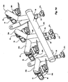
Figure 1 it is perspective view of a fuel-heating assembly applied to a fuel rail; -
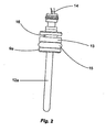
Figure 2 is a front view of a heating element used in the a fuel-heating assembly; -
Figure 3 is a sectional view of a first embodiment of the invention of the a fuel-heating assembly; and -
Figure 4 is a sectional view of a second embodiment of the a fuel-heating assembly. -
Figure 5 is a sectional view of a third embodiment of the fuel heating assembly of the invention. -
Figure 6 is a sectional view of a fourth embodiment of the fuel heating assembly of the invention. -
Figure 7 is a perspective view of a fifth embodiment of the fuel heating assembly of the invention. -
Figure 8 is a sectional view of fifth embodiment of the fuel heating assembly of the invention. -
Figure 9 is a perspective view of a sixth embodiment of the fuel heating assembly of the invention. -
Figure 10 is a sectional view of a detail of the fuel heating assembly. -
Figure 11 is a section view of a detail of the fuel heating assembly. -
Figure 12 is a perspective view of a heating assembly; -
Figure 13 is a perspective view of a detail of the heating assembly offigure 12 ; -
Figure 14 is a perspective view of a heating assembly; -
Figure 15 is a top view of the heating assembly offigure 14 ; -
Figure 16 is a side view of the heating assembly offigure 14 ; -
Figure 17 is an enlarged perspective view of a detail of the heating assemblies; -
Figure 18 is a perspective view of a heating assembly; -
Figure 19 is a side view of the heating assembly offigure 18 ; -
Figure 20 is a section of the heating assembly offigure 18 . - As it will be further described, the present invention solves the problems presented in the state of the art by means of a fuel-heating assembly.
- The assembly has an arrangement and devices which allow the cold start of an internal combustion engine using a fuel with high specific heat of vaporization without the need of an additional reservoir of starting fuel. Furthermore, it also allows lower emissions of hydrocarbons and pollutants during cold start and operation of the engine.
- The assembly for heating of this invention is shown inside a fuel rail, the devices thereof being fixed onto the fuel rail in such a way as to allow the desired fuel heating for the start of the engine, a sufficient temperature being reached for the burning of the fuel in the combustion chamber of the engine.
- As disclosed in the state of the art, it is not viable to heat all the fuel present at the rail, and the simple heating of the fuel contained in the injection valve is not enough for the adequate start of the internal combustion engine. Therefore, there is and adequate volume of fuel that must be heated in the rail.
- This adequate volume, as mentioned, is greater than the volume contained in the inner part of the injection valve and smaller that all the volume contained in the inner part of the rail. Thus, in case the volume of heated fuel is lower than the adequate volume, after the start the engine cannot keep up and does not operate in the correct way.
- On the other hand, if the volume of heated fuel is greater than the adequate volume, a very long pre-heating time is necessary, which is not desired by the user. In this second case, if the engine is actuated with a short pre-heating time, the fuel temperature is not high enough for the adequate operation of the engine, that is, it would not start, or even, if that happened, the emissions would be too high.
- Therefore, in such a way as to comply with all the requirements above, the present invention provides the heating of an ideal volume of fuel from heating elements and other devices of the assembly.
- As it can be seen from
figure 1 , afuel rail 1a has afuel inlet 2a. From this fuel inlet 2 fuel is provided from a pressurization system, which is not disclosed in the figures. The pressurization system consists basically of a fuel pump that pressurizes fuel in a piping which is connected to the fuel inlet 2, which, by its turn, keeps the inner part of the rail 1 pressurized with fuel. - At a
lower face 3 of therail 1 a there arefuel outlets 4a. At eachoutlet 4a there is connected arespective injection valve 5a, which atomizes the fuel before it is burnt in a combustion chamber of an internal combustion engine. - The
injection valves 5a are connected to therail 1 a by means of retention elements 6 which are, preferably, clamps 6a. Theseclamps 6a keep the injection valves fixed to the rail in a tight way, preventing thus the exit of pressurized fuel at the junction of theinjection valve 5a with thefuel outlet 4a. - Opposed to the
lower face 3 there is anupper face 7, which containsreception openings 8a ofheating elements 9a. Theopenings 8a allow that eachheating element 9a enters therail 1a and heats the fuel contained therein (the heating will be further explained). - Between
heating elements 9a andopenings 8a there are retention lugs 10 that perform the fixation and by means of this fixation, together with a sealing element (not shown infigure 1 ), prevents the exit of fuel through theopenings 8a. - To the
heating elements 9a there are linkedconnectors 11, which are responsible for the supply of electric power coming from a battery to theheating elements 9a. The electric power is transformed into thermal energy and transferred to the fuel at the inner part of the rail 1 through theheating elements 9a. - From
figure 2 theisolated heating element 9a can be seen, that is, not mounted onto theborehole 8a of the fuel rail 1. Theheating element 9a is similar to a heating element of the state of the art, but concentrates its heat distribution in a different way, as will be further explained. - The
heating element 9a has at one of its ends alance 12a which is responsible for the heat transfer to the fuel to be heated in the inner part ofrail 1 a. Thislance 12a is composed by an outer layer that is hot-gas and corrosion resistant. It is hot-gas resistant, once that at the inner part thereof there is a filament that transforms electric power into thermal energy, homogenously, to a compressed magnesium oxide powder. It is corrosion resistant, once that it is in direct contact with fuel, what may be highly corrosive, such as alcohol. - At a central portion of the
heating element 9a acentral body 13, which is responsible for the engaging of theheating element 9a to theborehole 8a of therail 1 a, there is a sealingring 15 that performs the sealing and prevents the leaking of fuel from therail 1 a through theborehole 8a. - At the other end of the heating element 9 there is fixed a
cable 14 that by its turn is linked to theconnector 11, responsible for the electric power supply. In ring-like groove 16 theclamps 10 are connected in such a way as to keep theheating element 9a fixed to the rail 1. - By means of
figures 3 and4 two possible first embodiments of the present invention can be verified. These figures are cross-sectional views of the present assembly, but have some differences that will be discussed herein below. - The first embodiment of the invention, seen in
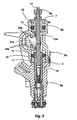
figure 3 , is a cross-sectional view of therail 1 a in which the sections of theinjection valves 5a and of theheating element 9a are shown. - The
injection valve 5a does not show any significant change when compared to a valve of the state of the art. The most significant difference is that it does not show a filter at thefuel inlet 17, or show a modified filter between alance 12a and aninner wall 18 ofinlet 17. - This filter is not disclosed in
figure 3 , but consists basically of a filter of the state of the art with an internal borehole, being resistant to high temperatures, as it is in direct contact with thelance 12a. - When this filter is not present in the
fuel inlet 17, another filter can optionally be mounted in thefuel opening 2a of therail 1a. - It can be seen that, at the
lower face 3 ofrail 1a theinjection valve 5a is engaged to thefuel outlet 4a. Thus, when an internal combustion engine is in operation, therail 1a supplies heated fuel for the respective atomization ininjection valve 5a. - Opposed to the
injection valve 5a, theheating element 9a is found at theupper face 7 and is engaged to theopening 8a of therail 1a. It is worthwhile to stress, as mentioned before, that the heating element is fixed by theclamp 16 and sealed by the sealingring 15 to theopening 8a. - The
lance 12a is inserted in the inner part of therail 1a where the fuel to be is heated is, being positioned in such a way at therail 1a that it concentrates in aheat transfer region 19a part of the fuel of the rail around it. In other words, only part of the fuel that is present in the rail 1 is able to receive heat coming from thelance 12a. That is due to the fact that it is aimed only the heating of part of the fuel of the rail in such a way that it can be assured that the fuel which will enter theinjection valve 5a is properly heated. That is because necessarily the fuel which will enter theinjection valve 5a will have to have passed through theheat transfer region 19a. - Thus, with this concentration of heat transfer of part of the fuel from
rail 1a, thelance 12a is able to have enough power to assure an injection of properly heated fuel to an internal combustion engine, which is one of the aims of the present invention. - Additionally,
fins 20a are positioned next to thelance 12a in such a way as to restrict the flow of all fuel from therail 1a to theheat transfer region 19a. That increases the required concentration. Therefore, it is thus assured that the fuel will be suitably heated. - The
fins 20a run along the extension of the inner part of therail 1a and have apassage 21 a between theheat transfer region 19a e the remaining of the inner part of rail 1. That allows the volume of fuel present inregion 19a to be adequate to be heated during the start of an internal combustion engine. It is noted that the position offins 20a does not depend on the operation of said assembly, in such a way that the former can show other geometries, such as, for example, instead offins 20a, it is possible to use an inner wall with holes. Later there will be described other enbodiements of the fins of the set, object of this invention, being that the essential is that the flow is restricted to theheating region 19a. - It must be noted that in the present embodiment, by the fact that the extension of the
lance 12a, the heat exchange area is larger than in the second embodiment, which will be further shown. However, it is necessary for theopening 8a to have a reference diameter to pre-position thelance 12a aiming at assuring it to be concentric in relation to thefuel inlet 17. - This reference diameter has a hole with controlled dimension so that, during the mounting of the assembly, the
lance 12a is with interference, allowing thus a fixation without clearance. - It must be further noted that with the insertion of
lance 12a at the inlet offuel 17, theheat transfer region 19a is significantly increased. - Now, from
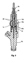
figure 4 the second embodiment of the invention can be observed. In this embodiment the difference is present in alance 12b in relation to the first embodiment that has alance 12a with a greater length. Once thelance 12b has a smaller length thanlance 12a it consequently transfers less heat to the fuel in oneheat transfer region 19b. Still, due to this smaller length, one of the ends of thelance 12b faces thefuel inlet 17, and therefore it is not necessarily concentric to this inlet. Thus, it does not require so precise a connection if compared to the first embodiment, thus making the mounting of the assembly easier and reducing the production costs of the present assembly. - Likewise, by the fact that the
lance 12b does not enter the injection valve 5 the filter can be kept inside said valve, differently from the first embodiment. - In this
figure 4 thefins 20a are not disclosed. However, the fins 20 may be present or not in both embodiments in such a way as to restrict the passage of non-heated fuel to theheat transfer region - The main difference in heating in both first embodiments is that in the first the pre-heating time is shorter than in the second, once due to the greater area of the
lance 12a, it has the possibility of transferring more heat. But in both cases the fuel inside the rail 1, provided to the injection valve 5 is heated in the required way. - From the other embodiments of the present invention, with the exception of the first one, only the main alterations of the embodiments will be pointed out, so that one should understand that, in the first embodiment, one has already pointed out how the heating assembly components interact.
- In order to exemplify another possible embodiment of the
lugs 20a, one can observe infigure 5 that arail 1c has a different internal configuration. Although this cross-sectional view of the assembly of the present invention has fewer details than the assemblies demonstrated before (the later embodiments also have fewer details), one can see aspear 12c of aheating element 9c in therail 1c in the direction of aninjection valve 5c. - In this rail the fuel flow is restricted by means of
flaps 20c, which enclose a portion of thespear 12c that is inserted into therail 1c. Theflaps 20c follow the axial direction of thespear 12c, so that apassage 22 permits a restricted fuel flow into aheat transfer region 19c, which in the present embodiment is the space formed between theflaps 20c and thespear 12c. In addition, in order for the fuel to have, along its path, greater contact with thespear 12c, theflaps 20c are fixed within the rail closer to theinjection valve 5c, opposed to theopening 8c. - Since there is a concentration of fuel flow in the
heat transfer region 19c, there is the guarantee of sufficient heating for a significant amount of fuel to be injected by theinjection valve 5c, without the need to heat the whole volume of fuel contained in therail 1c. - In addition, the heat convection of the fuel that is being heated close to the
spear 12c allows the fuel with a higher temperature inside the rail to concentrate closer to thepassageway 22. This occurs because the fuel with a higher temperature tends to concentrate in a higher portion of therail 1c. - Thus, upon starting the internal combustion engine, it is guaranteed that the first portions of fuel that pass through the
injection valve 5c will be those that are at a higher temperature. - As mentioned before, the
flaps 20c may be of different shapes, but the important thing is that they should increase and retain the concentration of heat in theheating region - In this last embodiment, there is a need for the
spear 12c to be concentric to theinjection valve 5c. However, there is the possibility of not using the spear concentrically to theinjection valve 5c. - The non-concentricity may be viewed in the embodiment represented in
figure 6 , in which the spear 124 is inserted into afuel rail 1d, so that, unlike the other embodiments, does not pass through therail 1d. This occurs in view of the displacement of an injection valve. In this case, the injection valve has not been shown; only afuel outlet 4d. - It is verified that this
fuel outlet 4d is displaced with respect to thespear 12d. However, enclosing a lower portion of thespear 12d flapheating region 19d, providing an accumulation of heated fuel close to thefuel outlet 4d. - Therefore, when the internal combustion engine is started, the fuel accumulated in the
heating region 19d is injected and the cold star of the engine is ensured. - Some projects of an internal combustion engine require a smaller fuel-heating assembly, due to the dimensions available in the engine cowling, as well as a lager amount of heated fuel.
- Thus, a positioning of the
spear - From
figure 7 one can see arail 1e, which consists of amain tube 24 and foursecondary tubes 25 having fluid communication with each other. This rail comprises afuel inlet 2e, through which fuel is pumped into therail 1e. - Each
secondary tube 25 comprises afuel outlet 4e at its central portion, to which aninjection valve 5e is connected. This injection valve is kept secured to thesecondary tube 25 by means of aclamp 6e. - The positioning of the
injection valve 5e is orthogonal to the axial direction of thesecondary tube 25, which in turn has an inclination with respect to the axial direction of themain tube 24. - in the present embodiment, the
secondary tubes 25 are parallel, andheating elements 9e are inserted at an opposite end between the attachment of thesecondary tubes 26 and themain tube 24. - The internal details of the assembly of the present embodiment can be viewed in
figure 8 , which is a sectional top view showing a part of themain tube 24, of thesecondary tube 25 and of theheating element 9e. - As can be seen in
figure 8 , theheating element 9e has aspear 12e, which follows the axial direction of thesecondary tube 25, as far as close to acommunication orifice 26 between thesecondary tube 25 and themain tube 24. It is from thecommunication orifice 26 that the fuel flows from themain tube 24 to thesecondary tube 25, which then flows to thefuel outlet 4e, until it is injected into an internal combustion engine through an injection valve that is not represented in the present embodiment. - The fuel flow from the
main tube 24 into thesecondary tube 25 is restricted by thecommunication orifice 26. In this way, the heating of the fuel is concentrated inside thesecondary tube 25, which configures aheating region 19e around thespear 12e. Again, it is ensured that the fuel which will be injected into the internal combustion engine is duly heated. - In this embodiment, the
secondary tube 25 is in a position slightly higher than themain tube 24. Consequently, due to the fact that the fuel having a higher temperature tends to rise, there is the guarantee that the more heated fuel will be the first to pass through thefuel outlet 4e upon starting the internal combustion engine. In addition, there is only a minor loss of heat of the fuel that is being heated in theheating region 19e through thecommunication orifice 26. - Each
heating region 19e of this embodiment is thermally isolated from another, since the heat supplied to the fuel close to eachspear 12e does not influence the heat supplied to the other heating regions 19 of the assembly according to the present invention. So, the same quantity of heat transmitted to the fuel that will be injected through each injection valve is ensured. In the other embodiments there was the possibility of the injection valve opposite the fuel inlet into said rails injecting a fuel with a higher temperature than that of the valve close to the fuel inlet. - The
secondary tubes 25 may further present different inclinations, depending upon the type of project of the internal combustion engine. This can be seen infigure 9 , where twosecondary tubes 25 are inclined opposite other twosecondary tubes 25. Since this is a fuel heating assembly for another type of internal combustion engine, the dimensions are different, as for example, the spacing betweensecondary tubes 25 and, consequently, betweeninjection plugs 5f. -
Heating element 9f should also follow the axial direction of each respectivesecondary tube 25. In this embodiment the electric connections of theinjection valves 5f face themain tube 24, so that the electrical feeds of thevalves 5f are located below therail 1f. - In
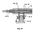
figures 10 and11 , one can see Internal variations of thesecondary tube 25, which are intended for reducing speed and concentration of the fuel that passes through the tube. - In
figure 10 , one can see theinjection valve fuel outlet heating element secondary tube 25 with thespear heating region secondary tube 25, a thread has been made, which performs the function of reducing the speed of the fuel, thus enabling a greater heat exchange in theheating region - On the other hand,
figure 11 shows theinjection valve fuel outlet heating element secondary tube 25 with thespear heating region - The inner wall of the
secondary tube 25 has an increase in section downstream of the fuel flow, that is to say, in the direction of flow its flume increases, so that there is a greater concentration of heat exchange close to thefuel outlet - Furthermore, as can be seen in
figure 12 , amain tube 24g has afuel inlet 2g, which is in communication with a fuel pressurization system. Themain tube 24g, an integral part of a fuel rail, which is also formed by twosecondary tubes 25g, has communication with saidsecondary tubes 25g. - Therefore, fuel can enter through the
fuel inlet 2g, pass through themain tube 24g, then through thesecondary tubes 25g, until it reaches theinjection valves 5g. - The
main tube 24g is elongate in shape, the Y-shapedsecondary tubes 25g being connected substantially at its ends. - The manner !n which the fuel gets into the
secondary tube 25g will be demonstrated later, but one can see in this figure that thesecondary tube 25g, due to its shape, has three ends, the first and second ends being attached toinjection valves 5g, that is to say, a par ofinjection valve 5g being connected to each secondary tube. This connection is carried out by means of afuel outlet 4g, theinjection valve 5g being retained in said outlet by means of aclamp 6g. - On the other hand, the third end of the
secondary tube 25g is connected both to themain tube 24g and to aheating element 9g. - As already demonstrated in one of the previously demonstrated heating assemblies, the
heating element 9g has alance 12g that gets into thesecondary tube 25g close to the connection between themain tube 24g and thesecondary tube 25g. - In addition, in the present embodiment some other accessories of the present heating assembly are employed, namely, a
connector 27g, which is responsible for the power supply connection to theheating element 9g. Another accessory is theconnector 28g, usually employed in the automotive industry, which supplies an electric stimulus/ pulse for the functioning of theinjection valve 5g. -
Figure 13 represents a part of the heating assembly offigure 1 , in which thesecondary tube 25g has been highlighted. One can see that only one of thesecondary tubes 25g and the respective pieces of equipment connected to it are represented, as for instance, theinjection valves 5g, thefuel outlets 4g and theclaims 6g. - One can further see that, at the end of the
secondary tube 25g, in which theheating element 9g is inserted, that there is acommunication bore 26g, which accounts for the passage of fuel from themain tube 24g into thesecondary tube 25g. This bore is nothing else than the intersection between the two tubes. - The fuel that enters into the
secondary tube 25g comes into contact with thelance 12g present inside said tube when it passes through thecommunication bore 26g. In this regard, during the heating, there is transfer of heat between thelance 12g and the fuel in contact with or close to said lance. In this way it is guaranteed that the fuel that comes out of themain tube 24g necessarily passes through a heat-transfer region 19g, which is formed by the confinement of the fuel that is substantially within thesecondary tube 25g. - The
lance 12g extends to the central portion of thesecondary tube 25g and, when the fuel is divided upon flowing towards theinjection valves 5g, it does not receive heat from thelance 12g any longer. However, this lance might eventually have other shapes, In order to extend in direction of thefuel outlets 4g. Therefore, theheating element 9g, more precisely thelance 12g, is substantially close to thefuel outlet 4g. - Thus, it is found that a volume smaller than the total volume of the rail is heated, which enables duly heated fuel to be supplied to the
injection valves 5g, or still naturally to an internal combustion engine, which is the ultimate objective of the invention. - It should be further pointed out that, as mentioned in one of the previous heating assemblies, there is a certain loss of heat through the
communication bore 26g, but it is not significant enough to impair the heating of the fuel that will follow for injection. - Another variant of the present invention can be seen in
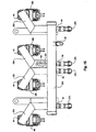
figure 14 . This variant is similar to the previous one, since it hasconnectors injection valves 5h,main tube 24h,fuel inlet 2h, which perform functions similar to those of theconnectors injection valves 5g,main tube 24g,fuel inlet 2g of the previous embodiment. - However, this variant, if compared with the previous one, has a larger number of
heating elements 9h, so that each element accounts for heating the fuel that will pass through aninjection valve 5h. - This same variant can be seen in a top view in
figure 15 as well. - In both
figures 14 and15 , one can note that thesecondary tube 25h has aheating element 9h, and in this embodiment thesecondary tube 25h is substantially L-shaped. However, this L shape has an obtuse angle in its inclination. Like the previous embodiment, alance 12h extends Inwardly of thesecondary tube 25h as far as close to said inclination. Thislance 12h could also extend as far as closer to thefuel outlet 4h. - In case of the lances of the present embodiment have the same power as the lances of the previous embodiment; more heat will be transferred to the fuel, since the present heating assembly has more heating elements.
- Notwithstanding, the secondary tubes are positioned both at the ends of the
main tube 24h and at the central portion thereof. This positioning may have different configurations, depending on the type of internal combustion engine that has to be fed. In other words, the engine design influences the positioning of thesecondary tubes 25h. - Further, one can observe that a
heat transfer region 19h is formed inside eachsecondary tube 25h, so that this region has a smaller volume than the whole contained volume of the fuel rail. So, only a part of the fuel is duly heated depending on the restriction of the heat and fuel that flows to said region. - In the same way as cited previously, this reduced but sufficient and duly heated volume enables the desired functioning of the internal combustion engine.
- A side view of the present embodiment can still be seen in
figure 16 . In this view one can clearly observe the Inclination positioning of the heating assembly. Theheating element 9h is inserted into a lower portion of thesecondary tube 25h opposite to the fuel flow direction, thus a heating concentration takes place where the heating element is inserted, since the fuel is gradually heated as it flows, because it is in contact with the lance of theheating element 9h. This allows the part in which thelance 12h is connected with the heating element, that is, its base, to be less heated. In this way one drastically minimizes the failures presented by overheating of the heating element, thus ensuring the correct functioning and robustness of the heating assembly of the present invention. - The pressurized fuel, upon entering into the
secondary tube 25h, flows in a direction opposite the force of gravity and is heated as it comes into contact with thelance 12h of theheating element 9h. In this way the colder fuel, upon entering into theheat transfer region 19h, is closer to the place where theheating element 9h is inserted. This minimizes further the problems with overheating of theheating element 9h. - In addition, since the heated fuel tends to rise, this positioning ensures that the fuel that is more heated in the
heat transfer region 19h is the one that enters into theinjection valve 5h. - This positioning of the
heating element 9h in a lower part of thesecondary tube 25h prevents a number of drawbacks relating to the heating of the element itself, as well as brings about a better distribution of heat to the fuel to be heated. - As mentioned before, the
connector - However, the fuel rail may be manufactured from a material that does not conduct electricity, as for example, plastic. For this type of material, a
connector 29 is necessary, as shown infigure 17 , which is attached to the heating element so as to provide grounding (id can be considered as a negative pole). In this way electric energy is adequately supplied to the heating element in the event that the material applied to the fuel rail is not electricity conducting one. - Finally, a last embodiment of the present invention can be seen in
figure 18 . This embodiment is quite similar to one of the embodiments of the previous heating assembly, but it has some significant differences, mainly as far as the positioning of the heating element is concerned. - Some components of the previous embodiments, as for example, the connectors 27, 28 and the clamps 6, perform the same function.
- This embodiment is in position different from those presented before, but, as pointed out above, it has
connectors - In said
figure 18 , a fuel rail comprises amain tube 24i, which has afuel inlet 2i. This inlet is connected to a fuel pressurization system, which naturally supplies pressurized fuel from a fuel tank. - The supplied fuel flows from the
fuel inlet 2i through themain tube 24i as far as at least oneinjection valve 5i. This valve performs the function of spraying fuel for feeding an internal combustion engine. - However, before the fuel reaches the
injection valve 5i, after coming out of themain tube 24i, it passes through asecondary tube 25i. In thissecondary tube 25i there is a heat transfer region 19i, which can be better viewed in the next figures. -
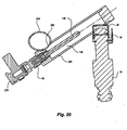
Figures 19 and20 disclose the heating assembly of figure 7CA in side views, the second one being represented in section. - In these figures the
injection valve 5i is connected to afuel outlet 4i, the valve being retained at the outlet by means of theclamp 6i. - One should note that the
injection valve 5i is in fluid communication both with thesecondary tube 25i and with themain tube 24i, which substantially form the fuel rail. In this regard, the fuel that comes out of themain tube 24i passes through a communication bore 26i, which restricts its access to thesecondary tube 25i. - Inside this latter tube the fuel is heated by the
heating element 9i, more precisely by the lance 12i of said element, in the heat transfer region 19i. This region is comprised within thesecondary tube 25i, so that a part of the fuel comprised in the rail is heated. In this way, one guarantees an adequate volume of heated fuel that, after passing through the heat transfer region 19i, flows out of theoutlets 4i until it is injected into an internal combustion engine through theinjection valve 5i. - As disclosed in the previous embodiments, the
heating element 9i is fitted into a lower portion of thesecondary tube 25i close to the communication bore 26i. So, the lance 12i extends close to the communication bore 26i in the direction of the fuel flow. This fuel flow is in the direction of thefuel outlet 4i. - Upon coming into contact with the lance 12i, the fuel begins to receive heat in the heat transfer region 19i, this region being delimited In this embodiment by the
secondary tube 25i. Thus, the volume of fuel is duly heated in said region. - Since the first portion of fuel that enters into the heat transfer region 19i is at a lower temperature and close to the base of the
heating element 9i, from which the lance 12i extends, the heating element is not subjected to high temperatures. Consequently, this element does not present overheating failures, so that the assembly becomes reliable, robust and of high efficiency. - For the event that the heating takes place before starting the internal combustion engine, that is to say, without there being fuel flow, the fuel in the heat transfer region 19i follows in the direction opposite the gravity, because it is at a higher temperature. Since this more heated fuel tends to rise, which fuel at a lower temperature tends to follow the direction of gravity and to occupy the space close to the communication bore 26i.
- However, the communication bore 26i is opposite to the
fuel outlet 4i and close to a lower portion of thesecondary tube 25i. In this way, the fuel passed through the heat transfer region 19i in a rising manner. Since the more heated fuel tends to rise within thesecondary tube 25i, one guarantees that the fuel that will pass through thefuel outlet 4i towards theinjection valve 5i is the one that is at a higher temperature. - In addition, in formation of gas during the heating, that is to say, when the fuel passed from the liquid state to the gaseous state, one further ensures that this gas will be as far as possible from the
heating element 9i. This prevents the lance 12i from remaining in contact with the fuel in gaseous state, thus preventing overheating. - The heating element 9, in the above described embodiments, may be a glow plug, as well as a ceramic material resistance with a positive temperature coefficient (PTC), thus providing a precise control of the heating temperature in proportion to the applied current.
- With the embodiments of the assembly thus shown it is possible to heat the fuel before the start of the internal combustion engine, in such a way that enough thermal energy is supplied so that the adequate volume of fuel, contained at the heat transfer region 19 reaches the necessary temperature. That allows the desired start, and after the start, the heat can still by degrees be supplied to the fuel, allowing thus that the air/fuel blend to be close to stoichimetric. This continuity in the heat supply to the fuel, even after the adequate start of the internal combustion engine, reduces the emissions, mainly HC.
- It must be further noticed that the alterations so presented do not require significant modifications in the project of a current engine, thus they can be carried out at a low cost. Further, the mounting of the assembly makes the maintenance of the components thereof easy, in case the eventual replacement thereof is necessary.
- As mentioned, the pre-heating time of the fuel before the start of the internal combustion engine is of great importance, once the user does not wait, or does not want to wait for a long time for the pre-heating period. This time is relatively short, as it is started as soon as there is an intention of the user in turning the engine on (generally by rotating the ignition key until the actuation of the electrical part of the engine) until the start of the engine itself.
- Thus, this invention comprises a method for the pre-heating of fuel for an internal combustion engine, which uses the heating assembly as described hereinabove.
- In the engines in which there is a pre-heating time, usually diesel engines, there is a light sign on an instrument panel which indicates a minimal time in which the user must wait for pre-heating.
- It happens that in Otto cycle the user is not used to such procedure. Thus, probably, the pre-heating would not occur in an efficient way.
- In order to avoid the necessity of an active intervention of the user to the correct performing of the pre-heating, the present method performs the pre-heating of fuel without the user being aware of his intervention.
- Normally, engines, so far described, are present in a vehicle, that is, an automobile. When there is the intention of the user in starting the engine of said automobile, he will have to open the door of the automobile. With this door opening, a relay connected to an electronic unit sends the information that the door has been opened. This allows the electronic unit to receive the information of a possible intention of starting the internal combustion engine. So, the electronic unit actuates the fuel heating assembly before even the insertion of the key in the ignition command of the automobile.
- Thus, some further heating seconds, before the engine starts are obtained. This is a significant difference for a satisfactory pre-heating.
- The actuation of the heating assembly may be carried out by other factors, such as, for example, the deactivation of the alarm of the automobile or even, the unlocking of the doors by remote control. The important is that the electronic unit receives the information of a possible intention from the user in willing to start the internal combustion engine and that, thus, the electronic unit may activate the heating assembly. It is also important that the user make his intervention in an unconscious way, so that his interactivity is not required in the present method.
- But, before the actuation performed by the electronic unit, the latter verifies if the external temperature is such that requires in fact a pre-heating of the fuel inside rail 1. A programming of the minimal temperature may be performed at the unit, so that there is the actuation of the pre-heating starting from this temperature as, for example, at temperatures below 20°C.
- After a pre-heating of the fuel, the user starts the internal combustion engine of the automobile, in such a way that the electronic unit keeps the heating assembly still active for approximately 1 minute, even after the start. This drastically minimizes the emissions of pollutants emission, manly HC, once the blend air/fuel comes close to the stoichimetric more quickly.
- Naturally, the time of permanence in which the heating assembly remains active is calculated in relation to the external temperature, this time varying for each type of engine to which the assembly is applied.
- In synthesis, the present method is comprised by the following steps:
- I - User intervention, as, for example, by opening the door of the automobile or turning the alarm of the vehicle off by remote control;
- II - Receiving of information of the intervention by the user by the electronic unit;
- III - Pre-heating of the fuel by the heating assembly actuated by the electronic unit;
- IV - Start of the internal combustion engine performed by the user after pre-heating; and
- V - Continuous heating of the fuel by the heating assembly, during a determined programmed time at the electronic unit after the start of the engine for the reduction of the emissions of pollutants, this interval can be, for example, of 1 minute.
- It must be noted that the heating of the heating assembly happens independently of the actuation of other components of the automobile, as, for example, operation of the fuel pump or injection valves, before the internal combustion engine is turned on.
- If by any reason after the preheating of the fuel the internal combustion engine is not turned on, the electronic unit deactivates the operation of the heating assembly in order to prevent the discharge of the battery of the automobile.
- Furthermore, the user can receive a sign from the electronic unit, which informs that the fuel is properly pre-heated before the start of the internal combustion engine, what will comply with the requirements mentioned above, that is, an ideal start of the internal combustion engine. This sign can be a sound sign, or even a light indication at the panel of the automobile.
- The two preferred examples of embodiments having been disclosed, it must be understood that the scope of the present invention encompasses other possible variations, being limited only by the content of the appended claims, there included possible equivalents.
Claims (29)
- A fuel-heating assembly for a internal combustion engine, which comprises:- a main tube (24, 24e, 24f, 24g, 24h, 24i) of a fuel rail (1e, 1f, 1g, 1h, 1i) linked to a fuel entry (2e, 2f, 2g, 2h, 2i) which is connected to a fuel pressurization system,- in the fuel rail (1e, 1f, 1g, 1h, 1i) a fuel outlet (4e, 4f, 4g, 4h, 4i) is present, which is in communication with at least one injection valve (5e, 5f, 5g, 5h, 5i);- at least one heating element (9e, 9f, 9g, 9h, 9i) which is inserted in the fuel rail (1e, 1f, 1g, 1h, 1i);- one heat transfer region (19e, 19f, 19g, 19h, 19i) in which the heating element (9e, 9f, 9g, 9h, 9i) is inserted, whereby the heat transfer region (19e, 19f, 19g, 19h, 19i) is upstream of the injection valve (5e, 5f, 5g, 5h, 5i);- the heat transfer region (19e, 19f, 19g, 19h, 19i) having a smaller volume than the total volume of the fuel rail (1e, 1f, 1g, 1h, 1i), wherein a communication orifice (26, 26e, 26f, 26g, 26h, 26i) is provided between the main tube (24, 24e, 24f, 24g, 24h, 24i) and the heat transfer region (19e, 19f, 19g, 19h, 19i)
characterized by the fact that the communication orifice (26, 26g, 26h, 26i) is in a lower portion of the rail (1e, 1f, 1g, 1h, 1i) in relation to said fuel outlet (4e, 4f, 4g, 4h, 4i). - A fuel-heating assembly according to claims 1, characterized by the fact that the axial direction of the heat element (9a, 9c, 9d, 9e, 9f, 9g, 9h, 9i) follows the direction of the fuel flow in the heat transfer region (19a, 19b, 19c, 19d, 19e, 19f, 19g, 19h, 19i).
- A fuel-heating assembly according to claims 1, characterized by the fact that the heating element (9a, 9c, 9d, 9e, 9f, 9g, 9h, 9i) has a heat lance (12a, 12b, 12c, 12d, 12e, 12f, 12g, 12h, 12i).
- A fuel-heating assembly according to one of the preceding claims, characterized by the fact that the heating element (9a, 9c, 9d, 9e, 9f, 9g, 9h, 9i) is a glow plug.
- A fuel-heating assembly according to claim 3, characterized by the fact that the lance (12a, 12b, 12c, 12d, 12e, 12f, 12g, 12h, 12i) is of ceramic material with a positive temperature coefficient (PTC).
- A fuel-heating assembly according to one of the preceding claims, characterized by the fact that the volume contained in the interior of the injection valve (5a, 5c, 5e, 5f, 5g, 5h, 5i) is smaller than the volume contained in the heat transfer region (19a, 19b, 19c, 19d, 19e, 19f, 19g, 19h, 19i).
- A fuel-heating assembly according to one of the preceding claims, characterized by the fact that the fuel rail (1 a, 1b, 1c, 1d, 1e, 1f, 1g,
1h, 1i) comprises a reception opening (8a, 8c) in which the lance (12a, 12b, 12c,12d, 12e, 12f, 12g, 12h, 12i) is inserted. - A fuel-heating assembly according to one of the preceding claims, characterized by the fact that the heating element (9a, 9c, 9d, 9e, 9f, 9g, 9h, 9i) is mounted on the fuel rail (1a, 1b, 1c, 1d, 1e, 1f, 1g, 1h, 1 i) opposite to the injection valve (5a, 5c)
- A fuel-heating assembly according to one of the preceding claims, characterized by the fact that fins (20a, 20c) are inserted in the interior of the fuel rail (1a, 1b, 1c, 1d, 1e, 1f, 1g, 1h, 1i) so as to limit part of the heat transfer region (19a, 19b, 19c, 19d, 19e, 19f, 19g, 19h, 19i).
- A fuel-heating assembly according to claim 9, characterized by the fact that the fins (20a, 20c, 20d) follow the axial direction of the heating lance (12a, 12b, 12c, 12d, 12e, 12f, 12g, 12h, 12i).
- A fuel-heating assembly according to claim 9 or 10, characterized by the fact that the fins (20a, 20c) are fixed near to the injection valve (5a, 5c).
- A fuel-heating assembly according to one of claims 9 to 11, characterized by the fact that the fins (20d) are in the form of an U-profile.
- A fuel-heating assembly according to one of the preceding claims, characterized by the fact that the fuel rail (1e, 1f, 1 g, 1h, 1i) has a main tube (24, 24g, 24h, 24i) and a secondary tube (25, 25g, 25h, 25i), whereby in the secondary tube (25, 25g, 25h, 25i) a heating element is inserted and the injection valve (5e, 5f, 5g, 5h, 5i) is connected.
- A fuel-heating assembly according to one of the preceding claims, characterized by the fact that the communication orifice (26, 26g, 26h, 26i) restricts the fuel flow from the main tube (24, 24g, 24h, 24i) to a secondary tube (25, 25g, 25h, 25i).
- A fuel-heating assembly according to claim 14, characterized by the fact that the lance (12e, 12f, 12g, 12h, 12i) follows the axial direction of the secondary tube (25, 25g, 25h, 25i).
- A fuel-heating assembly according to one of claims 14 or 15, characterized by the fact that the injection valve (5e, 5f, 5g, 5h, 5i) is connected to a central portion of the secondary tube (25, 25g, 25h, 25i).
- A fuel-heating assembly according to one of claims 14 to 16, characterized by the fact that the heat transfer region (19e, 19f, 19g, 19h, 19i) is limited by the secondary tube (25, 25g, 25h, 25i).
- A fuel-heating assembly according to one of claims 3 to 17, characterized by the fact that one end of the lance (12a, 12b, 12c, 12d, 12e, 12f, 12g, 12h, 12i) is inserted in a fuel inlet (17) of the injection valve (5a, 5c, 5e, 5f, 5g, 5h, 5i).
- A fuel-heating assembly according to one of claims 3 to 16, characterized by the fact that one end of the lance (12b) faces the fuel entry (17) of the injection valve (5b).
- A fuel-heating assembly according to one of the preceding claims, characterized by the fact that the heating element (9e, 9f, 9g, 9h, 9i) is inserted in an inferior portion of the secondary tube (25, 25e, 25g, 25h, 25i) opposite to the fuel flow direction.
- A fuel-heating assembly according to one of the preceding claims, characterized by the fact that the secondary tube (25g) has a Y-shape.
- A fuel-heating assembly according to one of the preceding claims, characterized by the fact that the heating element (9e, 9f, 9g, 9h, 9i) extends itself to a central portion of the secondary tube (25, 25e, 25g, 25h, 25i).
- A fuel-heating assembly according to one of the preceding claims, characterized by the fact that the lance (12a, 12b, 12c, 12d, 12e, 12f, 12g, 12h, 12i) extends in the direction of a fuel outlet (4a, 4c, 4d, 4e, 4f, 4g, 4h, 4i), so that said lance is near to said outlet.
- A fuel-heating assembly according to one of claims 13 to 23, characterized by the fact that the secondary tubes (25, 25e, 25f, 25g, 25h, 25i) are placed in the ends of the main tube (24, 24e, 24f, 24g, 24h, 24i) as well as the central portion of said main tube (24, 24e, 24f, 24g, 24h, 24i).
- A fuel-heating assembly according to one of claims 13 to 24, characterized by the fact that the fuel flows in the direction contrary to the gravity force inside the secondary tube (25, 25e, 25g, 25h, 25i).
- A fuel-heating assembly according to one of the preceding claims, characterized by the fact that a connector (29) is connected to the heating element (9e, 9f, 9g, 9h, 9i).
- A fuel-heating assembly according to one of the preceding claims, characterized by the fact that one injection valve (5e, 5f, 5g, 5h, 5i) is In fluid communication with the secondary tube (25, 25e, 25g, 25h, 25i), as well as the main tube (24, 24e, 24f, 24g, 24h, 24i), whereby these tubes form together a fuel rail.
- A fuel-heating assembly according to one of the preceding claims, characterized by the fact that the fuel flows in the direction of the fuel outlet (4a, 4c, 4d, 4e, 4f, 4g, 4h, 4i).
- A fuel-heating assembly according to one of the preceding claims, characterized by the fact that the fuel flows in opposite direction to the gravity.
Applications Claiming Priority (3)
| Application Number | Priority Date | Filing Date | Title |
|---|---|---|---|
| BRPI0502146 | 2005-06-06 | ||
| BRC10600645A BRPI0600645F1 (en) | 2006-02-15 | 2006-02-15 | fuel heating kit for an internal combustion engine |
| PCT/BR2006/000110 WO2006130938A1 (en) | 2005-06-06 | 2006-06-05 | A fuel-heating assembly and method for the pre-heating of fuel of an internal combustion engine |
Publications (2)
| Publication Number | Publication Date |
|---|---|
| EP1888910A1 EP1888910A1 (en) | 2008-02-20 |
| EP1888910B1 true EP1888910B1 (en) | 2010-11-10 |
Family
ID=36841103
Family Applications (1)
| Application Number | Title | Priority Date | Filing Date |
|---|---|---|---|
| EP06741337A Active EP1888910B1 (en) | 2005-06-06 | 2006-06-05 | A fuel-heating assembly and method for the pre-heating of fuel of an internal combustion engine |
Country Status (7)
| Country | Link |
|---|---|
| US (1) | US7942136B2 (en) |
| EP (1) | EP1888910B1 (en) |
| JP (1) | JP4834728B2 (en) |
| AR (1) | AR053515A1 (en) |
| AT (1) | ATE487877T1 (en) |
| DE (1) | DE602006018136D1 (en) |
| WO (1) | WO2006130938A1 (en) |
Cited By (5)
| Publication number | Priority date | Publication date | Assignee | Title |
|---|---|---|---|---|
| WO2013068526A1 (en) | 2011-11-11 | 2013-05-16 | Mahle International Gmbh | Fuel injection system and preheating device |
| DE102012220429A1 (en) | 2012-11-09 | 2014-05-15 | Mahle International Gmbh | Preheating device for a fuel injection system |
| DE102012220433A1 (en) | 2012-11-09 | 2014-05-15 | Mahle International Gmbh | Fuel injection system with preheater |
| DE102012220432A1 (en) | 2012-11-09 | 2014-05-15 | Mahle International Gmbh | Preheating device for a fuel injection system |
| US10690101B2 (en) | 2017-09-15 | 2020-06-23 | Indian Motorcycle International, LLC | Wheeled vehicle |
Families Citing this family (80)
| Publication number | Priority date | Publication date | Assignee | Title |
|---|---|---|---|---|
| BRPI0504047C1 (en) * | 2005-09-12 | 2007-07-31 | Fiat Automoveis Sa | cold start auxiliary system for alcohol and flex engines with inlet air and alcohol heating |
| BRPI0703129B1 (en) | 2007-07-19 | 2016-12-20 | Bosch Do Brasil | fuel gallery |
| KR101290976B1 (en) | 2007-08-06 | 2013-07-30 | 현대자동차주식회사 | Ethanol Temperature Rising System |
| DE102007049973A1 (en) | 2007-10-18 | 2009-04-23 | Robert Bosch Gmbh | Heating device for liquid fuels and the like |
| US20090107473A1 (en) * | 2007-10-26 | 2009-04-30 | Continental Automotive Systems Us, Inc. | Cold start structure for multipoint fuel injection systems |
| US9034210B2 (en) | 2007-12-05 | 2015-05-19 | Epcos Ag | Feedstock and method for preparing the feedstock |
| US7973639B2 (en) | 2007-12-05 | 2011-07-05 | Epcos Ag | PTC-resistor |
| US8074625B2 (en) | 2008-01-07 | 2011-12-13 | Mcalister Technologies, Llc | Fuel injector actuator assemblies and associated methods of use and manufacture |
| US8365700B2 (en) | 2008-01-07 | 2013-02-05 | Mcalister Technologies, Llc | Shaping a fuel charge in a combustion chamber with multiple drivers and/or ionization control |
| US8635985B2 (en) | 2008-01-07 | 2014-01-28 | Mcalister Technologies, Llc | Integrated fuel injectors and igniters and associated methods of use and manufacture |
| US8387599B2 (en) | 2008-01-07 | 2013-03-05 | Mcalister Technologies, Llc | Methods and systems for reducing the formation of oxides of nitrogen during combustion in engines |
| US7628137B1 (en) | 2008-01-07 | 2009-12-08 | Mcalister Roy E | Multifuel storage, metering and ignition system |
| US8413634B2 (en) | 2008-01-07 | 2013-04-09 | Mcalister Technologies, Llc | Integrated fuel injector igniters with conductive cable assemblies |
| US8561598B2 (en) | 2008-01-07 | 2013-10-22 | Mcalister Technologies, Llc | Method and system of thermochemical regeneration to provide oxygenated fuel, for example, with fuel-cooled fuel injectors |
| US8225768B2 (en) | 2008-01-07 | 2012-07-24 | Mcalister Technologies, Llc | Integrated fuel injector igniters suitable for large engine applications and associated methods of use and manufacture |
| US8047182B2 (en) * | 2008-02-13 | 2011-11-01 | Millenium Industries | Fuel delivery system for heating fuel therein |
| ITTO20080271A1 (en) | 2008-04-08 | 2009-10-09 | Eltek Spa | "HEATING DEVICE FOR FUEL FUEL PIPES, FUEL SUPPLY PIPE AND COMBUSTION ENGINE" |
| BRPI0805484A2 (en) * | 2008-12-02 | 2010-08-24 | Magneti Marelli Sist Ltda | fuel gallery with axially mounted heating system for ethanol cold start system |
| US8151771B2 (en) | 2008-12-10 | 2012-04-10 | Ford Global Techologies, Llc | Fuel preheat for engine start |
| JP5265396B2 (en) * | 2009-01-23 | 2013-08-14 | 三桜工業株式会社 | Fuel heating system |
| EP2249023A1 (en) | 2009-05-06 | 2010-11-10 | Continental Automotive GmbH | Fuel rail heating system of a combustion engine and fuel injection system |
| WO2011028225A1 (en) * | 2009-08-27 | 2011-03-10 | Mcalister Technoligies, Llc | Method and system of thermochemical regeneration to provide oxygenated fuel, for example, with fuel-cooled fuel injectors |
| CN102713244A (en) | 2009-08-27 | 2012-10-03 | 麦卡利斯特技术有限责任公司 | Shaped supply fuel in combustors with multiple drivers and/or ionization control |
| EP2470485A4 (en) | 2009-08-27 | 2012-12-26 | Mcalister Technologies Llc | CERAMIC ISOLATOR AND METHODS OF USE AND MANUFACTURE |
| ATE545779T1 (en) * | 2009-09-29 | 2012-03-15 | Honda Motor Co Ltd | FUEL HEATING DEVICE |
| JP5303417B2 (en) * | 2009-09-29 | 2013-10-02 | 本田技研工業株式会社 | Fuel supply device |
| JP5303418B2 (en) * | 2009-09-29 | 2013-10-02 | 本田技研工業株式会社 | Fuel supply device |
| JP5351696B2 (en) * | 2009-10-05 | 2013-11-27 | 日本特殊陶業株式会社 | Fuel heating device |
| JP5240859B2 (en) * | 2009-10-05 | 2013-07-17 | 日本特殊陶業株式会社 | Heater for fuel heating device and fuel heating device using the heater |
| IT1396306B1 (en) * | 2009-11-06 | 2012-11-16 | Eltek Spa | ELECTRIC HEATER, HEATING DEVICE AND HEATING SYSTEM. |
| KR20120086375A (en) | 2009-12-07 | 2012-08-02 | 맥알리스터 테크놀로지즈 엘엘씨 | Adaptive control system for fuel injectors and igniters |
| CN102844540A (en) | 2010-02-13 | 2012-12-26 | 麦卡利斯特技术有限责任公司 | Methods and systems for adaptively cooling combustion chambers in engines |
| US20110297753A1 (en) | 2010-12-06 | 2011-12-08 | Mcalister Roy E | Integrated fuel injector igniters configured to inject multiple fuels and/or coolants and associated methods of use and manufacture |
| US8205805B2 (en) | 2010-02-13 | 2012-06-26 | Mcalister Technologies, Llc | Fuel injector assemblies having acoustical force modifiers and associated methods of use and manufacture |
| JP5510015B2 (en) * | 2010-02-26 | 2014-06-04 | 株式会社デンソー | Fuel supply device for internal combustion engine |
| DE102010034411B4 (en) * | 2010-08-14 | 2018-10-11 | Audi Ag | Internal combustion engine with injection valve |
| US8069845B2 (en) * | 2010-10-11 | 2011-12-06 | Ford Global Technologies Llc | Fuel heating during cold start in a direct-injection gasoline engine |
| US8528519B2 (en) | 2010-10-27 | 2013-09-10 | Mcalister Technologies, Llc | Integrated fuel injector igniters suitable for large engine applications and associated methods of use and manufacture |
| BRPI1005341B1 (en) | 2010-12-02 | 2016-12-20 | Bosch Do Brasil | plastic fuel tank with heating system |
| US8091528B2 (en) | 2010-12-06 | 2012-01-10 | Mcalister Technologies, Llc | Integrated fuel injector igniters having force generating assemblies for injecting and igniting fuel and associated methods of use and manufacture |
| BRPI1100311B1 (en) * | 2011-02-11 | 2022-01-04 | Magneti Marelli Sistemas Automotivos Indústria E Comércio Ltda. - Divisão Controle Motor | FUEL HEATER SET WITH FUSE EFFECT |
| US8820275B2 (en) | 2011-02-14 | 2014-09-02 | Mcalister Technologies, Llc | Torque multiplier engines |
| DE102011007327B4 (en) * | 2011-04-13 | 2024-01-18 | Robert Bosch Gmbh | Injection device and internal combustion engine |
| US8919377B2 (en) | 2011-08-12 | 2014-12-30 | Mcalister Technologies, Llc | Acoustically actuated flow valve assembly including a plurality of reed valves |
| CN103890343B (en) | 2011-08-12 | 2015-07-15 | 麦卡利斯特技术有限责任公司 | Systems and methods for improved engine cooling and power generation |
| DE102011113699A1 (en) * | 2011-09-20 | 2013-03-21 | Lurgi Gmbh | Process for the production of synthesis gas |
| US9206775B2 (en) | 2012-02-01 | 2015-12-08 | United Technologies Corporation | Fuel preheating using electric pump |
| FR2989127B1 (en) * | 2012-04-04 | 2015-10-09 | Peugeot Citroen Automobiles Sa | METHOD FOR STARTING THE STARTING OF A THERMAL MOTOR SUPPLIED BY A FUEL CONTAINING ETHANOL |
| JP6107521B2 (en) * | 2012-10-29 | 2017-04-05 | 株式会社デンソー | Fuel rail |
| US9115325B2 (en) | 2012-11-12 | 2015-08-25 | Mcalister Technologies, Llc | Systems and methods for utilizing alcohol fuels |
| JP6182905B2 (en) * | 2013-03-01 | 2017-08-23 | 株式会社デンソー | Fuel rail |
| JP5548288B2 (en) * | 2013-03-11 | 2014-07-16 | 三桜工業株式会社 | Fuel heating system |
| JP6032120B2 (en) * | 2013-03-12 | 2016-11-24 | 株式会社デンソー | Fuel heating device and fuel rail provided with the same |
| JP5873039B2 (en) * | 2013-04-12 | 2016-03-01 | 本田技研工業株式会社 | Fuel supply device |
| JP5987793B2 (en) * | 2013-07-10 | 2016-09-07 | 株式会社デンソー | Fuel rail |
| JP6064827B2 (en) * | 2013-08-01 | 2017-01-25 | 株式会社デンソー | Fuel rail |
| JP6133722B2 (en) * | 2013-08-01 | 2017-05-24 | 株式会社デンソー | Fuel rail |
| JP6274799B2 (en) * | 2013-09-20 | 2018-02-07 | 株式会社デンソー | Fuel heating system and fuel rail using the same |
| JP6285133B2 (en) * | 2013-09-20 | 2018-02-28 | 株式会社デンソー | Fuel heating system and fuel rail using the same |
| JP6254403B2 (en) * | 2013-09-20 | 2017-12-27 | 株式会社デンソー | Fuel heating system and fuel rail using the same |
| JP6290715B2 (en) * | 2014-06-02 | 2018-03-07 | 株式会社デンソー | Fuel rail |
| DE102014215981A1 (en) * | 2014-08-12 | 2016-02-18 | Robert Bosch Gmbh | Rail assembly with fuel heater |
| JP2016114012A (en) * | 2014-12-17 | 2016-06-23 | 愛三工業株式会社 | Fuel supply unit |
| JP6156545B2 (en) * | 2016-04-26 | 2017-07-05 | 株式会社デンソー | Fuel rail and fuel injection device using the same |
| DE102016223716A1 (en) * | 2016-11-29 | 2018-05-30 | Mahle International Gmbh | Operating method for an internal combustion engine |
| BR102016029084A2 (en) * | 2016-12-12 | 2018-07-17 | Mahle Metal Leve S.A. | fuel heating system |
| JP6337076B2 (en) * | 2016-12-22 | 2018-06-06 | 株式会社デンソー | Fuel heating system and fuel rail using the same |
| JP6438082B2 (en) * | 2017-07-24 | 2018-12-12 | 株式会社デンソー | Fuel heating system and fuel rail using the same |
| US10794346B2 (en) | 2019-01-24 | 2020-10-06 | Caterpillar Inc. | Fuel rail |
| DE102019220377A1 (en) * | 2019-12-20 | 2021-06-24 | Robert Bosch Gmbh | Fluid distributor for an injection system, in particular a fuel distributor strip for a fuel injection system for mixture-compressing, externally ignited internal combustion engines |
| BR102019027845A2 (en) * | 2019-12-26 | 2021-07-06 | Robert Bosch Limitada | system and method of managing the temperature of fuel injected in internal combustion engines |
| BR102019027843A2 (en) * | 2019-12-26 | 2021-07-06 | Robert Bosch Limitada | system and method of managing the temperature of fuel injected in internal combustion engines |
| US11078878B1 (en) * | 2020-01-22 | 2021-08-03 | Fca Us Llc | Fuel rail nozzle retention bracket |
| JP7519878B2 (en) * | 2020-10-30 | 2024-07-22 | マルヤス工業株式会社 | Heated fuel delivery pipe |
| WO2022226612A1 (en) * | 2021-04-30 | 2022-11-03 | Robert Bosch Limitada | Device for heating fuel and assembly for injecting fuel |
| US12577920B2 (en) | 2021-12-20 | 2026-03-17 | Robert Bosch Limitada | Method for diagnosing faults in the operation of a fuel heating system associated with an internal combustion engine |
| CN118786280A (en) * | 2022-02-28 | 2024-10-15 | 罗伯特·博世有限公司 | Fuel dispenser with plug closure system for fuel filler assembly |
| TR2022009107A2 (en) * | 2022-06-03 | 2023-12-21 | Bosch Sanayi Ve Ticaret Anonim Sirketi | A FUEL RAIL AND A SIMPLE METHOD FOR PREPARING THIS FUEL RAIL |
| JP7478791B2 (en) | 2022-09-30 | 2024-05-07 | 本田技研工業株式会社 | Fuel supply system |
| JP7482962B2 (en) | 2022-09-30 | 2024-05-14 | 本田技研工業株式会社 | Fuel supply system |
Family Cites Families (11)
| Publication number | Priority date | Publication date | Assignee | Title |
|---|---|---|---|---|
| US5216990A (en) * | 1991-08-02 | 1993-06-08 | Rolf Moosmann | Glow plug for internal combustion diesel engine |
| US5529035A (en) * | 1994-11-08 | 1996-06-25 | Hitachi America, Ltd. | Cold start fuel injector with heater |
| JPH08338339A (en) | 1995-06-15 | 1996-12-24 | Isuzu Motors Ltd | diesel engine |
| USH1820H (en) * | 1998-12-22 | 1999-12-07 | Caterpillar Inc. | Method for heating actuating fluid in a fuel system |
| JP4085535B2 (en) * | 1999-09-06 | 2008-05-14 | 日産自動車株式会社 | High pressure piping for fuel injection |
| US6209500B1 (en) * | 2000-01-19 | 2001-04-03 | Ford Global Technologies, Inc. | Cold start fuel preheat system for internal combustion engine |
| DE10105760A1 (en) | 2001-02-08 | 2002-09-05 | Sascha Joos | Viscosity reduction of vegetable oil fuel for a diesel engine is carried out adjacent the engine block in a heating unit having glow plugs with electrical control of the temperature |
| JP3900514B2 (en) * | 2001-11-07 | 2007-04-04 | 株式会社デンソー | Heater-mounted fuel injection system |
| US20030234004A1 (en) * | 2002-06-21 | 2003-12-25 | Forgue John R. | No-return loop fuel system |
| DE10340159A1 (en) | 2003-09-01 | 2005-04-07 | Audi Ag | High pressure fuel injection system as common rail injection system |
| DE102005036952A1 (en) * | 2005-08-05 | 2007-02-08 | Robert Bosch Gmbh | Fuel injection system with at least one fuel injection valve and a heatable adapter further includes a fuel rail with a thermal switch connected to the heatable adapter and a device producing an external contact |
-
2006
- 2006-06-05 WO PCT/BR2006/000110 patent/WO2006130938A1/en not_active Ceased
- 2006-06-05 AT AT06741337T patent/ATE487877T1/en not_active IP Right Cessation
- 2006-06-05 US US11/921,696 patent/US7942136B2/en active Active
- 2006-06-05 JP JP2008515005A patent/JP4834728B2/en not_active Expired - Fee Related
- 2006-06-05 EP EP06741337A patent/EP1888910B1/en active Active
- 2006-06-05 AR ARP060102344A patent/AR053515A1/en active IP Right Grant
- 2006-06-05 DE DE602006018136T patent/DE602006018136D1/en active Active
Cited By (8)
| Publication number | Priority date | Publication date | Assignee | Title |
|---|---|---|---|---|
| WO2013068526A1 (en) | 2011-11-11 | 2013-05-16 | Mahle International Gmbh | Fuel injection system and preheating device |
| DE102011086201A1 (en) | 2011-11-11 | 2013-05-16 | Mahle International Gmbh | Fuel injection system and preheater |
| DE102012220429A1 (en) | 2012-11-09 | 2014-05-15 | Mahle International Gmbh | Preheating device for a fuel injection system |
| DE102012220433A1 (en) | 2012-11-09 | 2014-05-15 | Mahle International Gmbh | Fuel injection system with preheater |
| DE102012220432A1 (en) | 2012-11-09 | 2014-05-15 | Mahle International Gmbh | Preheating device for a fuel injection system |
| WO2014072171A1 (en) | 2012-11-09 | 2014-05-15 | Mahle International Gmbh | Pre-heating device for a fuel injection system |
| WO2014072166A1 (en) | 2012-11-09 | 2014-05-15 | Mahle International Gmbh | Fuel injection system having a pre-heating device |
| US10690101B2 (en) | 2017-09-15 | 2020-06-23 | Indian Motorcycle International, LLC | Wheeled vehicle |
Also Published As
| Publication number | Publication date |
|---|---|
| JP2008542622A (en) | 2008-11-27 |
| EP1888910A1 (en) | 2008-02-20 |
| DE602006018136D1 (en) | 2010-12-23 |
| ATE487877T1 (en) | 2010-11-15 |
| WO2006130938A1 (en) | 2006-12-14 |
| US20090133676A1 (en) | 2009-05-28 |
| US7942136B2 (en) | 2011-05-17 |
| JP4834728B2 (en) | 2011-12-14 |
| AR053515A1 (en) | 2007-05-09 |
Similar Documents
| Publication | Publication Date | Title |
|---|---|---|
| EP1888910B1 (en) | A fuel-heating assembly and method for the pre-heating of fuel of an internal combustion engine | |
| EP1934467B1 (en) | Cold start up auxiliary system for alcohol and flex engines with air-inlet and alcohol warm up | |
| US5056495A (en) | Fuel supply device and heating device | |
| CN86106537A (en) | The vehicle heater of actuating by fuel oil | |
| US9752514B2 (en) | Thermal management system for the feeding of fuel in internal combustion engines | |
| US20050193994A1 (en) | Fuel delivery system | |
| WO2004092558A2 (en) | Capillary heating control and fault detection system and methodology for fuel system in an internal combustion engine | |
| EP1392964A4 (en) | Fuel delivery system | |
| US9175647B2 (en) | Hot oil thermal battery | |
| US6807946B2 (en) | Fuel supply device for internal combustion engine | |
| EP0964149B1 (en) | Air and fuel system for carburetor and fuel injection systems. | |
| US8371274B2 (en) | Vehicle with an internal combustion engine for ethanol-containing fuels, and an auxiliary heater | |
| US9068488B2 (en) | Vaporization device for a motor vehicle exhaust system, exhaust system for a motor vehicle and method for producing a vaporization device | |
| CN213899119U (en) | Detachable cold starting device for two-stroke engine | |
| US20160076424A1 (en) | Coolant heating method for releasing reductant | |
| US20070022976A1 (en) | Performance of interal combustion engines | |
| AU2006259392A1 (en) | Improving performance of internal combustion engines | |
| BRPI0600645B1 (en) | FUEL HEATING ASSEMBLY | |
| KR940004474Y1 (en) | Fuel heating device | |
| EP4556794B1 (en) | Parking heater with high energy utilization rate | |
| KR101009640B1 (en) | Dummy plug for diesel engine | |
| CA2241290C (en) | Air and fuel system for carburetor and fuel injection systems | |
| KR100505295B1 (en) | Fuel heating system for an LPG engine | |
| KR20090028772A (en) | Performance improvement system and method of internal combustion engine | |
| KR890006054Y1 (en) | Secondary air supply of automotive oil saver |
Legal Events
| Date | Code | Title | Description |
|---|---|---|---|
| PUAI | Public reference made under article 153(3) epc to a published international application that has entered the european phase |
Free format text: ORIGINAL CODE: 0009012 |
|
| 17P | Request for examination filed |
Effective date: 20071220 |
|
| AK | Designated contracting states |
Kind code of ref document: A1 Designated state(s): AT BE BG CH CY CZ DE DK EE ES FI FR GB GR HU IE IS IT LI LT LU LV MC NL PL PT RO SE SI SK TR |
|
| DAX | Request for extension of the european patent (deleted) | ||
| RIN1 | Information on inventor provided before grant (corrected) |
Inventor name: THOEMMES, FRANZ Inventor name: BRUNOCILLA, MARCELLO F.RUA ANA CLAUDINA DA COSTA Inventor name: VASCONCELOS, ALVARO AUGUSTO Inventor name: ARAUJO, MARCOS M.RUA EGBERTO FERREIRA DE ARRUDA Inventor name: LEPSCH, FERNANDO Inventor name: BERTOLUCCI FILHO, ROSALVO Inventor name: MARRON, FERNANDO AUGUSTO |
|
| DAX | Request for extension of the european patent (deleted) | ||
| GRAP | Despatch of communication of intention to grant a patent |
Free format text: ORIGINAL CODE: EPIDOSNIGR1 |
|
| GRAC | Information related to communication of intention to grant a patent modified |
Free format text: ORIGINAL CODE: EPIDOSCIGR1 |
|
| GRAC | Information related to communication of intention to grant a patent modified |
Free format text: ORIGINAL CODE: EPIDOSCIGR1 |
|
| RIC1 | Information provided on ipc code assigned before grant |
Ipc: F02M 69/46 20060101ALI20100525BHEP Ipc: F02M 55/02 20060101ALI20100525BHEP Ipc: F02M 53/02 20060101AFI20100525BHEP |
|
| GRAS | Grant fee paid |
Free format text: ORIGINAL CODE: EPIDOSNIGR3 |
|
| GRAA | (expected) grant |
Free format text: ORIGINAL CODE: 0009210 |
|
| AK | Designated contracting states |
Kind code of ref document: B1 Designated state(s): AT BE BG CH CY CZ DE DK EE ES FI FR GB GR HU IE IS IT LI LT LU LV MC NL PL PT RO SE SI SK TR |
|
| REG | Reference to a national code |
Ref country code: GB Ref legal event code: FG4D |
|
| REG | Reference to a national code |
Ref country code: CH Ref legal event code: EP |
|
| REG | Reference to a national code |
Ref country code: IE Ref legal event code: FG4D |
|
| REF | Corresponds to: |
Ref document number: 602006018136 Country of ref document: DE Date of ref document: 20101223 Kind code of ref document: P |
|
| REG | Reference to a national code |
Ref country code: SE Ref legal event code: TRGR |
|
| REG | Reference to a national code |
Ref country code: NL Ref legal event code: VDEP Effective date: 20101110 |
|
| LTIE | Lt: invalidation of european patent or patent extension |
Effective date: 20101110 |
|
| PG25 | Lapsed in a contracting state [announced via postgrant information from national office to epo] |
Ref country code: LT Free format text: LAPSE BECAUSE OF FAILURE TO SUBMIT A TRANSLATION OF THE DESCRIPTION OR TO PAY THE FEE WITHIN THE PRESCRIBED TIME-LIMIT Effective date: 20101110 |
|
| PG25 | Lapsed in a contracting state [announced via postgrant information from national office to epo] |
Ref country code: FI Free format text: LAPSE BECAUSE OF FAILURE TO SUBMIT A TRANSLATION OF THE DESCRIPTION OR TO PAY THE FEE WITHIN THE PRESCRIBED TIME-LIMIT Effective date: 20101110 Ref country code: IS Free format text: LAPSE BECAUSE OF FAILURE TO SUBMIT A TRANSLATION OF THE DESCRIPTION OR TO PAY THE FEE WITHIN THE PRESCRIBED TIME-LIMIT Effective date: 20110310 Ref country code: SI Free format text: LAPSE BECAUSE OF FAILURE TO SUBMIT A TRANSLATION OF THE DESCRIPTION OR TO PAY THE FEE WITHIN THE PRESCRIBED TIME-LIMIT Effective date: 20101110 Ref country code: AT Free format text: LAPSE BECAUSE OF FAILURE TO SUBMIT A TRANSLATION OF THE DESCRIPTION OR TO PAY THE FEE WITHIN THE PRESCRIBED TIME-LIMIT Effective date: 20101110 Ref country code: CY Free format text: LAPSE BECAUSE OF FAILURE TO SUBMIT A TRANSLATION OF THE DESCRIPTION OR TO PAY THE FEE WITHIN THE PRESCRIBED TIME-LIMIT Effective date: 20101110 Ref country code: PT Free format text: LAPSE BECAUSE OF FAILURE TO SUBMIT A TRANSLATION OF THE DESCRIPTION OR TO PAY THE FEE WITHIN THE PRESCRIBED TIME-LIMIT Effective date: 20110310 Ref country code: NL Free format text: LAPSE BECAUSE OF FAILURE TO SUBMIT A TRANSLATION OF THE DESCRIPTION OR TO PAY THE FEE WITHIN THE PRESCRIBED TIME-LIMIT Effective date: 20101110 Ref country code: BG Free format text: LAPSE BECAUSE OF FAILURE TO SUBMIT A TRANSLATION OF THE DESCRIPTION OR TO PAY THE FEE WITHIN THE PRESCRIBED TIME-LIMIT Effective date: 20110210 Ref country code: LV Free format text: LAPSE BECAUSE OF FAILURE TO SUBMIT A TRANSLATION OF THE DESCRIPTION OR TO PAY THE FEE WITHIN THE PRESCRIBED TIME-LIMIT Effective date: 20101110 |
|
| PG25 | Lapsed in a contracting state [announced via postgrant information from national office to epo] |
Ref country code: ES Free format text: LAPSE BECAUSE OF FAILURE TO SUBMIT A TRANSLATION OF THE DESCRIPTION OR TO PAY THE FEE WITHIN THE PRESCRIBED TIME-LIMIT Effective date: 20110221 Ref country code: EE Free format text: LAPSE BECAUSE OF FAILURE TO SUBMIT A TRANSLATION OF THE DESCRIPTION OR TO PAY THE FEE WITHIN THE PRESCRIBED TIME-LIMIT Effective date: 20101110 Ref country code: CZ Free format text: LAPSE BECAUSE OF FAILURE TO SUBMIT A TRANSLATION OF THE DESCRIPTION OR TO PAY THE FEE WITHIN THE PRESCRIBED TIME-LIMIT Effective date: 20101110 |
|
| PG25 | Lapsed in a contracting state [announced via postgrant information from national office to epo] |
Ref country code: DK Free format text: LAPSE BECAUSE OF FAILURE TO SUBMIT A TRANSLATION OF THE DESCRIPTION OR TO PAY THE FEE WITHIN THE PRESCRIBED TIME-LIMIT Effective date: 20101110 Ref country code: PL Free format text: LAPSE BECAUSE OF FAILURE TO SUBMIT A TRANSLATION OF THE DESCRIPTION OR TO PAY THE FEE WITHIN THE PRESCRIBED TIME-LIMIT Effective date: 20101110 Ref country code: SK Free format text: LAPSE BECAUSE OF FAILURE TO SUBMIT A TRANSLATION OF THE DESCRIPTION OR TO PAY THE FEE WITHIN THE PRESCRIBED TIME-LIMIT Effective date: 20101110 Ref country code: RO Free format text: LAPSE BECAUSE OF FAILURE TO SUBMIT A TRANSLATION OF THE DESCRIPTION OR TO PAY THE FEE WITHIN THE PRESCRIBED TIME-LIMIT Effective date: 20101110 |
|
| PLBE | No opposition filed within time limit |
Free format text: ORIGINAL CODE: 0009261 |
|
| STAA | Information on the status of an ep patent application or granted ep patent |
Free format text: STATUS: NO OPPOSITION FILED WITHIN TIME LIMIT |
|
| 26N | No opposition filed |
Effective date: 20110811 |
|
| REG | Reference to a national code |
Ref country code: DE Ref legal event code: R097 Ref document number: 602006018136 Country of ref document: DE Effective date: 20110811 |
|
| REG | Reference to a national code |
Ref country code: CH Ref legal event code: PL |
|
| REG | Reference to a national code |
Ref country code: IE Ref legal event code: MM4A |
|
| PG25 | Lapsed in a contracting state [announced via postgrant information from national office to epo] |
Ref country code: IE Free format text: LAPSE BECAUSE OF NON-PAYMENT OF DUE FEES Effective date: 20110605 Ref country code: LI Free format text: LAPSE BECAUSE OF NON-PAYMENT OF DUE FEES Effective date: 20110630 Ref country code: CH Free format text: LAPSE BECAUSE OF NON-PAYMENT OF DUE FEES Effective date: 20110630 |
|
| PG25 | Lapsed in a contracting state [announced via postgrant information from national office to epo] |
Ref country code: MC Free format text: LAPSE BECAUSE OF NON-PAYMENT OF DUE FEES Effective date: 20110630 |
|
| PG25 | Lapsed in a contracting state [announced via postgrant information from national office to epo] |
Ref country code: LU Free format text: LAPSE BECAUSE OF NON-PAYMENT OF DUE FEES Effective date: 20110605 |
|
| PG25 | Lapsed in a contracting state [announced via postgrant information from national office to epo] |
Ref country code: TR Free format text: LAPSE BECAUSE OF FAILURE TO SUBMIT A TRANSLATION OF THE DESCRIPTION OR TO PAY THE FEE WITHIN THE PRESCRIBED TIME-LIMIT Effective date: 20101110 |
|
| PG25 | Lapsed in a contracting state [announced via postgrant information from national office to epo] |
Ref country code: HU Free format text: LAPSE BECAUSE OF FAILURE TO SUBMIT A TRANSLATION OF THE DESCRIPTION OR TO PAY THE FEE WITHIN THE PRESCRIBED TIME-LIMIT Effective date: 20101110 |
|
| PG25 | Lapsed in a contracting state [announced via postgrant information from national office to epo] |
Ref country code: GR Free format text: LAPSE BECAUSE OF FAILURE TO SUBMIT A TRANSLATION OF THE DESCRIPTION OR TO PAY THE FEE WITHIN THE PRESCRIBED TIME-LIMIT Effective date: 20101110 |
|
| PGFP | Annual fee paid to national office [announced via postgrant information from national office to epo] |
Ref country code: SE Payment date: 20150618 Year of fee payment: 10 |
|
| PGFP | Annual fee paid to national office [announced via postgrant information from national office to epo] |
Ref country code: IT Payment date: 20150619 Year of fee payment: 10 Ref country code: BE Payment date: 20150622 Year of fee payment: 10 |
|
| REG | Reference to a national code |
Ref country code: FR Ref legal event code: PLFP Year of fee payment: 11 |
|
| PG25 | Lapsed in a contracting state [announced via postgrant information from national office to epo] |
Ref country code: BE Free format text: LAPSE BECAUSE OF NON-PAYMENT OF DUE FEES Effective date: 20160630 |
|
| REG | Reference to a national code |
Ref country code: SE Ref legal event code: EUG |
|
| PG25 | Lapsed in a contracting state [announced via postgrant information from national office to epo] |
Ref country code: SE Free format text: LAPSE BECAUSE OF NON-PAYMENT OF DUE FEES Effective date: 20160606 |
|
| REG | Reference to a national code |
Ref country code: FR Ref legal event code: PLFP Year of fee payment: 12 |
|
| PG25 | Lapsed in a contracting state [announced via postgrant information from national office to epo] |
Ref country code: IT Free format text: LAPSE BECAUSE OF NON-PAYMENT OF DUE FEES Effective date: 20160605 |
|
| REG | Reference to a national code |
Ref country code: FR Ref legal event code: PLFP Year of fee payment: 13 |
|
| P01 | Opt-out of the competence of the unified patent court (upc) registered |
Effective date: 20230530 |
|
| PGFP | Annual fee paid to national office [announced via postgrant information from national office to epo] |
Ref country code: GB Payment date: 20240620 Year of fee payment: 19 |
|
| PGFP | Annual fee paid to national office [announced via postgrant information from national office to epo] |
Ref country code: FR Payment date: 20240619 Year of fee payment: 19 |
|
| PGFP | Annual fee paid to national office [announced via postgrant information from national office to epo] |
Ref country code: DE Payment date: 20250624 Year of fee payment: 20 |
|
| GBPC | Gb: european patent ceased through non-payment of renewal fee |
Effective date: 20250605 |
|
| PG25 | Lapsed in a contracting state [announced via postgrant information from national office to epo] |
Ref country code: GB Free format text: LAPSE BECAUSE OF NON-PAYMENT OF DUE FEES Effective date: 20250605 |
|
| PG25 | Lapsed in a contracting state [announced via postgrant information from national office to epo] |
Ref country code: FR Free format text: LAPSE BECAUSE OF NON-PAYMENT OF DUE FEES Effective date: 20250630 |