EP1887167A2 - Verbesserungen bei und im Zusammenhang mit Pfahlrammen - Google Patents
Verbesserungen bei und im Zusammenhang mit Pfahlrammen Download PDFInfo
- Publication number
- EP1887167A2 EP1887167A2 EP20070114208 EP07114208A EP1887167A2 EP 1887167 A2 EP1887167 A2 EP 1887167A2 EP 20070114208 EP20070114208 EP 20070114208 EP 07114208 A EP07114208 A EP 07114208A EP 1887167 A2 EP1887167 A2 EP 1887167A2
- Authority
- EP
- European Patent Office
- Prior art keywords
- post
- mast
- support frame
- holder
- driver
- Prior art date
- Legal status (The legal status is an assumption and is not a legal conclusion. Google has not performed a legal analysis and makes no representation as to the accuracy of the status listed.)
- Withdrawn
Links
Images


Classifications
-
- E—FIXED CONSTRUCTIONS
- E04—BUILDING
- E04H—BUILDINGS OR LIKE STRUCTURES FOR PARTICULAR PURPOSES; SWIMMING OR SPLASH BATHS OR POOLS; MASTS; FENCING; TENTS OR CANOPIES, IN GENERAL
- E04H17/00—Fencing, e.g. fences, enclosures, corrals
- E04H17/26—Devices for erecting or removing fences
- E04H17/261—Devices for erecting or removing fences for post and wire handling
- E04H17/263—Devices for erecting or removing fences for post and wire handling for erecting posts
Definitions
- the present invention relates to post drivers and in particular to post drivers which are used by farmers to drive posts into the ground.
- post drivers To be effective, such post drivers must be easily attachable to farm vehicles, such as tractors and must also, in use, be able to accommodate uneven terrain and be able to drive posts into hill sides and inclines.
- One particularly useful design for a post driver which provides these requirements is that described in UK Patent Publication No. 2420367 (Brennan et al. ).
- This document discloses a post driver having a support frame for attachment to the three-point linkage of a tractor.
- the support frame carries an upright mast.
- a post holder is slidably mounted on the mast.
- a hammer is slidably mounted on the mast above the post holder and has associated means for raising the hammer on the mast for dropping onto the post holder to drive a post held by the post holder into the ground.
- a further important requirement is that a post, having been driven into the ground, is appropriately aligned in the ground.
- stones, rocks, tree roots and the like to obstruct the path of a post as it is being driven into the ground and this typically causes the post, on hitting the obstruction, to move off its intended path and become misaligned in the ground.
- the mast of the post driver Before a post is driven into the ground it is necessary for the mast of the post driver to be aligned to the vertical in order that the post being driven may be positioned vertically in the ground.
- post drivers are often used on uneven terrain, including hill sides and inclines, it is usually necessary for the mast to be aligned to the vertical prior to the post being driven into the ground.
- the term 'comprise' may, under varying jurisdictions be provided with either an exclusive or inclusive meaning.
- the term comprise shall have an inclusive meaning - i.e. that it may be taken to mean an inclusion of not only the listed components it directly references, but also other non-specified components. Accordingly, the term 'comprise' is to be attributed with as broader interpretation as possible within any given jurisdiction and this rationale should also be used when the terms 'comprised' and/or 'comprising' are used.
- a post driver including:
- Such an arrangement is particularly useful as it provides a means by which the alignment of a post may be corrected once it has been driven into the ground.
- the use of the alignment means will be advantageous as the alignment of the post can be restored without manual intervention by operators. It will be appreciated that this will provide a significant time saving in terms of labour overheads as additional operators will not be required for this heretobefore manual post alignment.
- a mast is mounted on the support frame, the post holder is mounted on the mast by means of a carriage which is slidably mounted on the mast, the post holder being rotatably mounted on the carriage.
- actuating means is provided on the carriage which is operable for rotating the post holder on the carriage.
- the actuating means is a ram mounted between the carriage and the post holder.
- the ram is mounted on the carriage by a trunnion which pivotally engages a complementary pivot mount on the carriage.
- the post holder has a post receiving socket for reception of an upper end of the post.
- the post receiving socket is a force fit on the end of an associated post.
- the post receiving socket is demountably secured on the post holder.
- post receiving sockets of different sizes may be provided to accommodate posts of different size.
- the means for urging the post holder downwardly is a hammer which is slidably mounted on the mast above the post holder, with means for raising the hammer on the mast for dropping onto the post holder to drive a post into the ground.
- a striker plate is mounted on the carriage above the post holder for engagement by the hammer.
- the striker plate may carry a depending post end engaging spike.
- the support frame has means for attachment to the three-point linkage of a tractor vehicle.
- the post driver includes a main support frame having ground engaging legs, a main mast mounted on the support frame and a support mast slidably mounted on the main mast, a pile driving hammer slidably mounted on a hammer guide rail on the support mast, a pulley mounted adjacent the upper free end of the support mast, a flexible connector connected to the main mast and the hammer via the pulley, a lifting ram connected between the support mast and the main mast for raising the support mast and a tilting ram connected between the main mast and the support frame for raising the main mast.
- the post alignment means comprises biasing means for movement under load.
- the feature of the invention advantageously provides a degree of "give" in the alignment means so that during alignment of a post in the ground the alignment is not so rigid in operation so as to cause damage to the post driver or the post holder.
- means for adjusting the upright orientation of the mast on the support frame, plumb sensing means for the mast, said mast adjusting means being operable in response to the plumb sensing means to vertically align the mast.
- said mast adjusting means including means for laterally tilting the mast on the support frame about a first pivot axis and means for pivoting the support frame on the three-point linkage of the tractor on which the post driver is mounted for tilting the mast about a second pivot axis perpendicular to the first pivot axis.
- the mast adjustment means comprises a controller operably connected to a ram on the top link of the three-point linkage and operably connected to a mast tilt ram connected between the support frame and the mast, said rams being operable by the controller to move the mast in mutually perpendicular planes for vertical alignment of the mast.
- the plum sensing means comprises sensors associated with each mast adjustment ram, each sensor having a pendulum pivotally mounted on a support, said pendulum having an arm mounted between a pair of switches, misalignment of the mast causing a corresponding pivoting movement of the pendulum for engagement of the arm with a switch which is operably connected to the associated mast alignment ram to operate said ram to bring the mast back into alignment.
- a post driver including:
- the tilt ram is operable to control the lateral tilt of the mast and the three point linkage mounting means is operable to control the transverse tilt of the mast.
- the tilt ram and the three point linkage mounting means are independently operable by the control means.
- the sensing means comprises one or more sensors for determining whether the mast is aligned to the vertical.
- control means operates the tilt ram and the three point linkage mounting means in response to mast tilt signals provided by the sensors.
- the sensors utilise a pendulum to determine whether the mast is vertical.
- the sensors are mercury tilt switches.
- the sensors are electronic tilt switches.
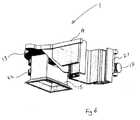
- a post holder for a post driver, indicated generally by the reference numeral 2 according to the invention.
- the post driver 2 comprises a main support frame 3 with means 3a for attachment to the three-point linkage of a tractor (not shown).
- the support frame 3 has ground engaging legs 4.
- a main mast 5 is mounted on the support frame 3 and a support mast 6 slidably mounted on the main mast 5.
- a pile driving hammer 7 which is slidably mounted on a hammer guide rail 8 on the support mast 6.
- a pulley 9 is mounted adjacent the upper free end of the support mast 6.
- a flexible connector, in the form of a rope (not shown) is connected to the main mast 5 and the hammer 7 via the pulley 9.
- a lifting ram (not shown) is connected between the support mast 6 and the main mast 5 for raising the support mast 6 on the main mast 5.
- a tilting ram 10 connected between the main mast 5 and the support frame 3 for tilting the main mast 5 relative to the support frame 3 by means of a pivot connection 23 between the main mast 5 and the support frame 3.
- the post holder 1 comprises a flat striker plate 13 fast to a post support member 14 forming a carriage which is slidably mounted on the support mast 6 below the pile driving hammer 7.
- the flat plate carries a depending post end engaging spike.
- Slide channels 24 at an inner end of the carriage 14 engage complementary slide flanges or rails on the support mast 6.
- a post 11 is placed on the ground and engaged by the post holder 1 and the lifting ram is operated to raise the support mast 6 relative to the main mast 5.
- the pile driving hammer 7 is lifted double the distance as the rope is anchored at mounting 12 on the main mast 5.
- the pile driving hammer 7 is raised to the top of the support mast 6 so that when the support mast 6 is fully raised, and the lifting ram is released, the pile driving hammer 7 is also released so that it will immediately travel down and drop against the flat plate 13 of the post holder 1.
- the post 11 is driven into the ground.
- the flat plate 13 of the post holder 1 carries a depending rotatably mounted post retaining socket 15 for holding the upper end of the post 11 which is to be driven into the ground.
- the post retaining socket 15 is sized to provide a force fit for the upper end of the post 11 and is removable from the flat plate 13, which is thus arranged to carry post retaining sockets 15 of different sizes to accommodate posts 11 of different sizes.
- the post driver 1 further comprises alignment means, indicated generally by the reference numeral 16, to rotate the post retaining socket 15 relative to the flat plate 13 to correct the alignment of a post 11 which has been previously driven into the ground.
- Hydraulic ram 17 provides the alignment means 16 in the embodiment shown.
- the alignment means 16 is so configured to provide biasing means for movement of the socket 15 carrying the post 11 under load.
- the hydraulic ram 17 is connected from the support member 14 to the post retaining socket 15 via a lever arm 22 which is fast to the post retaining socket 15.
- the lever arm 22 is connected to the ram 17 at pivot 18.
- a trunnion 19 is mounted intermediate the ends of the hydraulic ram 17.
- the trunnion 19 is pivotally mounted by pivot 20 to a side plate 21 mounted to a side of the support member 14 beneath the flat plate 13.
- actuation of the ram 17 causes the socket 15 to rotate relative to the flat plate 13, causing a post 11 held in the socket 15 to also rotate about a vertical longitudinal axis X of the post 11 and thus have its alignment in the ground corrected as required.
- an apparatus indicated generally by the reference numeral 31 for aligning the mast, indicated generally by the reference numeral 32, of a post driver, indicated generally by the reference numeral 33.
- the post driver 33 comprises a support frame 34 having ground engaging legs 35 and three-point linkage mounting means, indicated generally by the reference numeral 36 is provided for securing the support frame 34 to the three-point linkage of a tractor (not shown).
- the mast 32 comprises a main mast 46, which is mounted pivotally by a pivot bracket 44 on the support frame 34, and a support mast 47 slidably mounted on the main mast 46.
- a pulley 48 is mounted adjacent the upper free end of the support mast 47 and a pile driving hammer 49 is slidably mounted on a hammer guide rail 50 on the support mast 47.
- a flexible connector 51 such as a rope or cable is connected to the main mast 46 and the hammer 49 via the pulley 48.
- a lifting ram (not shown) is connected between the support mast 47 and the main mast 46 for raising the support mast 47 up the main mast 46.
- a post holder 52 is slidably mounted on the main mast 46 below the pile driving hammer 49.
- the support frame 34 is a two-part support frame having a main support frame 37 which carries the three-point linkage mounting means comprising of a top link ram 38 and two connectors 39 for connection to the three-point linkage of the tractor.
- the main support frame 37 is connected to a further mast support frame 40 by a pair of spaced-apart telescopic cross members 41, movable by rams 42 (Fig. 10).
- the mast support frame 40 has a telescopic top bar 43, again operated by a further ram (not shown).
- the mast 32 is mounted on the top bar 43 by a pivot bracket 44 and a tilt ram 45 is connected between the mast 32 and the support frame 34.
- a counterweight 46 is provided on the top bar 43.
- the main support frame 37 is thus connected to mounting arms of the three-point linkage and the mast support frame 40, which is slidable laterally with respect to the three-point linkage, on the main support frame 37.
- the mast support frame 40 is thus slidable towards and away from the three-point linkage mounting arms.
- plumb sensing means for sensing when the mast 32 is not vertically aligned.
- the sensing means 53 comprises one or more sensors 54 for determining whether or not the mast 32 is aligned to the vertical.
- the sensors 54 can equally well be positioned at different locations on the post driver 33.
- the sensor 54 positioned on the support frame 34 will in most circumstances be positioned on the back of the mast 32 very close to the sensor 54 on the pivot bracket 44.
- the sensing means 53 or more specifically, the sensors 54 are connected to control means, indicated by the reference numeral 60, for operating the tilt ram 45 and the three-point linkage mounting means to align the mast 32 to the vertical.
- the tilt ram 45 is operable to control the lateral tilt of the mast 32, that is the back and forth movement of the mast 32
- the three-point linkage top link ram 38 is operable to control the transverse tilt, that is the sideways movement of the mast 32.
- the control means 60 operates the tilt ram 45 and the three-point linkage top link ram 38 in response to mast tilt signals provided by the sensors 54. In this way, the mast 32 can be automatically aligned when it is not vertical.
- a control panel or console (not shown) is also provided so that all operators need to do is push a button to activate the apparatus 31 so that the sensing means 53 will determine whether the mast 32 is vertical and then transmit the appropriate signals to align the mast 32 if it is unaligned.
- the main mast 32 can be tilted in the direction of the arrow A by the tilt ram 45.
- the main mast 32 can also be moved towards and away from the three-point linkage in the direction of the arrow B by the rams 42 and finally, it can be pivoted in the direction of the arrow C by the three-point linkage top link ram 38. This allows for the post driver to be easily vertically aligned depending on the terrain.
- the tilt ram 45 and the three-point linkage mounting means 36 are independently operable and adjustable by the control means 60. Actuation of the rams 45, 38 pivots the mast 32 about mutually perpendicular axes.
- the sensor 54 comprises a pendulum 55 to determine whether the mast 32 is vertical, the pendulum 55 being pivotally attached to a backing plate 56 which is in turn secured to the respective part 39, 44 of the post driver 33.
- the sensor 54 also includes bumper portions 57 to restrict movement of the pendulum 55.
- Switches 58 are also shown, the switches 58 being moved between on and off positions by movement of the pendulum arm 59 in response to the mast 32 being in an off vertical position.
- solenoids not shown
- solenoids associated with the post driver 33 to activate the post driver hydraulics (namely, rams 45 and 38) to align the mast 32 so that it is parallel with the pendulum 55 and therefore vertically aligned.
- sensors 54 used may also be mercury tilt switches or electronic tilt switches as required or as desired.
Landscapes
- Engineering & Computer Science (AREA)
- Architecture (AREA)
- Civil Engineering (AREA)
- Structural Engineering (AREA)
- Placing Or Removing Of Piles Or Sheet Piles, Or Accessories Thereof (AREA)
Applications Claiming Priority (2)
| Application Number | Priority Date | Filing Date | Title |
|---|---|---|---|
| IE20060592 | 2006-08-10 | ||
| IE20060699 | 2006-09-26 |
Publications (1)
| Publication Number | Publication Date |
|---|---|
| EP1887167A2 true EP1887167A2 (de) | 2008-02-13 |
Family
ID=38658705
Family Applications (1)
| Application Number | Title | Priority Date | Filing Date |
|---|---|---|---|
| EP20070114208 Withdrawn EP1887167A2 (de) | 2006-08-10 | 2007-08-10 | Verbesserungen bei und im Zusammenhang mit Pfahlrammen |
Country Status (2)
| Country | Link |
|---|---|
| EP (1) | EP1887167A2 (de) |
| IE (2) | IE20070574A1 (de) |
Cited By (10)
| Publication number | Priority date | Publication date | Assignee | Title |
|---|---|---|---|---|
| EP2039851A2 (de) | 2007-09-20 | 2009-03-25 | Joseph Anthony Brennan | Pfahlramme |
| GB2460742A (en) * | 2008-06-13 | 2009-12-16 | John Mowatt Bryce | Rotating post holder for post driver |
| EP2159332A2 (de) | 2008-08-27 | 2010-03-03 | Joseph Anthony Brennan | Pfahlramme |
| GB2500295A (en) * | 2012-01-13 | 2013-09-18 | Joseph Anthony Brennan | Post holder assembly for a post driver |
| AU2010226950B2 (en) * | 2009-10-06 | 2014-04-03 | Munro Engineers Pty Ltd | Improved Post Driver |
| GB2546318A (en) * | 2016-01-15 | 2017-07-19 | Brennan Fencing Ltd | A rotator cap assembly for a post driver |
| WO2019100115A1 (en) * | 2017-11-24 | 2019-05-31 | Hugh Mckay | Fencing system |
| US11713591B2 (en) * | 2017-06-29 | 2023-08-01 | William R. Tanner | Systems, devices, and/or methods for driving posts |
| AU2017390178B2 (en) * | 2017-01-09 | 2024-02-08 | Tricord Solutions, Inc. | Impacting apparatus |
| GB2635605A (en) * | 2023-09-14 | 2025-05-21 | Brennan Fencing Ltd | Post driver |
-
2007
- 2007-08-10 IE IE20070574A patent/IE20070574A1/en unknown
- 2007-08-10 EP EP20070114208 patent/EP1887167A2/de not_active Withdrawn
- 2007-08-10 IE IES20070575 patent/IES20070575A2/xx not_active IP Right Cessation
Cited By (14)
| Publication number | Priority date | Publication date | Assignee | Title |
|---|---|---|---|---|
| EP2039851A2 (de) | 2007-09-20 | 2009-03-25 | Joseph Anthony Brennan | Pfahlramme |
| GB2460742A (en) * | 2008-06-13 | 2009-12-16 | John Mowatt Bryce | Rotating post holder for post driver |
| GB2460742B (en) * | 2008-06-13 | 2012-06-13 | John Mowatt Bryce | Improvements in and relating to post drivers |
| EP2159332A2 (de) | 2008-08-27 | 2010-03-03 | Joseph Anthony Brennan | Pfahlramme |
| AU2010226950B2 (en) * | 2009-10-06 | 2014-04-03 | Munro Engineers Pty Ltd | Improved Post Driver |
| GB2500295B (en) * | 2012-01-13 | 2017-12-20 | Anthony Brennan Joseph | A post holder assembly for a post driver |
| GB2500295A (en) * | 2012-01-13 | 2013-09-18 | Joseph Anthony Brennan | Post holder assembly for a post driver |
| GB2546318A (en) * | 2016-01-15 | 2017-07-19 | Brennan Fencing Ltd | A rotator cap assembly for a post driver |
| GB2546318B (en) * | 2016-01-15 | 2021-10-06 | Brennan Fencing Ltd | A rotator cap assembly for a post driver |
| AU2017390178B2 (en) * | 2017-01-09 | 2024-02-08 | Tricord Solutions, Inc. | Impacting apparatus |
| EP3565689B1 (de) * | 2017-01-09 | 2024-12-11 | Tricord Solutions, Inc. | Schlagvorrichtung |
| US11713591B2 (en) * | 2017-06-29 | 2023-08-01 | William R. Tanner | Systems, devices, and/or methods for driving posts |
| WO2019100115A1 (en) * | 2017-11-24 | 2019-05-31 | Hugh Mckay | Fencing system |
| GB2635605A (en) * | 2023-09-14 | 2025-05-21 | Brennan Fencing Ltd | Post driver |
Also Published As
| Publication number | Publication date |
|---|---|
| IE20070574A1 (en) | 2008-06-11 |
| IES20070575A2 (en) | 2008-08-20 |
Similar Documents
| Publication | Publication Date | Title |
|---|---|---|
| EP1887167A2 (de) | Verbesserungen bei und im Zusammenhang mit Pfahlrammen | |
| JP5836240B2 (ja) | 乗用型田植機 | |
| GB2485918A (en) | Post driver with slidable positioning means | |
| US6889777B2 (en) | Implement for driving posts | |
| IES84940Y1 (en) | Improvements in and relating to post drivers | |
| US7296636B1 (en) | Apparatus for driving fence posts and the like | |
| JP3221669U (ja) | 杭打ちアタッチメント及び杭打ち機 | |
| KR101864098B1 (ko) | 고소작업차의 바스켓 수평 유지장치 | |
| IE87010B1 (en) | A post driver | |
| GB2423549A (en) | Adjustable post driver | |
| CN101300116A (zh) | 具有自动调平的操作手柄的混凝土锯 | |
| JP2000170200A (ja) | フロントローダの装着構造 | |
| JP2009082042A (ja) | 耕深制御装置 | |
| JP6073447B2 (ja) | 乗用型田植機 | |
| GB2441071A (en) | Post driver with independent hydraulic legs | |
| US12173470B2 (en) | Apparatus and method for enhanced skid loader grading control | |
| IE20170018A1 (en) | A post driver assembly | |
| EP2481273A1 (de) | Verbesserte obere Kulissenanordnung | |
| EP2039851A2 (de) | Pfahlramme | |
| JPH0755860Y2 (ja) | 苗植機 | |
| AU2014100050A4 (en) | Driver Apparatus | |
| JP2016032474A5 (de) | ||
| GB2474758A (en) | Attachment apparatus for a post driver | |
| JP2004065024A (ja) | 対地作業機 | |
| JP3437470B2 (ja) | 作業車の制御装置 |
Legal Events
| Date | Code | Title | Description |
|---|---|---|---|
| PUAI | Public reference made under article 153(3) epc to a published international application that has entered the european phase |
Free format text: ORIGINAL CODE: 0009012 |
|
| AK | Designated contracting states |
Kind code of ref document: A2 Designated state(s): AT BE BG CH CY CZ DE DK EE ES FI FR GB GR HU IE IS IT LI LT LU LV MC MT NL PL PT RO SE SI SK TR |
|
| AX | Request for extension of the european patent |
Extension state: AL BA HR MK YU |
|
| STAA | Information on the status of an ep patent application or granted ep patent |
Free format text: STATUS: THE APPLICATION IS DEEMED TO BE WITHDRAWN |
|
| 18D | Application deemed to be withdrawn |
Effective date: 20140301 |