EP3565689B1 - Schlagvorrichtung - Google Patents
Schlagvorrichtung Download PDFInfo
- Publication number
- EP3565689B1 EP3565689B1 EP17890017.1A EP17890017A EP3565689B1 EP 3565689 B1 EP3565689 B1 EP 3565689B1 EP 17890017 A EP17890017 A EP 17890017A EP 3565689 B1 EP3565689 B1 EP 3565689B1
- Authority
- EP
- European Patent Office
- Prior art keywords
- spring
- anvil assembly
- spring anvil
- impacting
- striker
- Prior art date
- Legal status (The legal status is an assumption and is not a legal conclusion. Google has not performed a legal analysis and makes no representation as to the accuracy of the status listed.)
- Active
Links
Images


Classifications
-
- E—FIXED CONSTRUCTIONS
- E02—HYDRAULIC ENGINEERING; FOUNDATIONS; SOIL SHIFTING
- E02D—FOUNDATIONS; EXCAVATIONS; EMBANKMENTS; UNDERGROUND OR UNDERWATER STRUCTURES
- E02D7/00—Methods or apparatus for placing sheet pile bulkheads, piles, mouldpipes, or other moulds
- E02D7/02—Placing by driving
- E02D7/06—Power-driven drivers
- E02D7/08—Drop drivers with free-falling hammer
-
- B—PERFORMING OPERATIONS; TRANSPORTING
- B25—HAND TOOLS; PORTABLE POWER-DRIVEN TOOLS; MANIPULATORS
- B25C—HAND-HELD NAILING OR STAPLING TOOLS; MANUALLY OPERATED PORTABLE STAPLING TOOLS
- B25C1/00—Hand-held nailing tools; Nail feeding devices
- B25C1/04—Hand-held nailing tools; Nail feeding devices operated by fluid pressure, e.g. by air pressure
- B25C1/047—Mechanical details
-
- B—PERFORMING OPERATIONS; TRANSPORTING
- B25—HAND TOOLS; PORTABLE POWER-DRIVEN TOOLS; MANIPULATORS
- B25C—HAND-HELD NAILING OR STAPLING TOOLS; MANUALLY OPERATED PORTABLE STAPLING TOOLS
- B25C1/00—Hand-held nailing tools; Nail feeding devices
- B25C1/06—Hand-held nailing tools; Nail feeding devices operated by electric power
-
- B—PERFORMING OPERATIONS; TRANSPORTING
- B25—HAND TOOLS; PORTABLE POWER-DRIVEN TOOLS; MANIPULATORS
- B25D—PERCUSSIVE TOOLS
- B25D1/00—Hand hammers; Hammer heads of special shape or materials
- B25D1/16—Hand hammers; Hammer heads of special shape or materials having the impacting head in the form of a sleeve slidable on a shaft, e.g. hammers for driving a valve or draw-off tube into a barrel
-
- E—FIXED CONSTRUCTIONS
- E04—BUILDING
- E04H—BUILDINGS OR LIKE STRUCTURES FOR PARTICULAR PURPOSES; SWIMMING OR SPLASH BATHS OR POOLS; MASTS; FENCING; TENTS OR CANOPIES, IN GENERAL
- E04H17/00—Fencing, e.g. fences, enclosures, corrals
- E04H17/26—Devices for erecting or removing fences
- E04H17/261—Devices for erecting or removing fences for post and wire handling
- E04H17/263—Devices for erecting or removing fences for post and wire handling for erecting posts
Definitions
- the present disclosure relates to impacting apparatuses, and, more particularly, to such impacting apparatus for driving fence posts, breaking concrete, setting rivets, driving nails and otherwise performing multiple continuous impacts.
- Impacting apparatuses also referred to herein as a "driver,” “gun” or “device” known in the art often may be configured for an entirely portable operation.
- Contractors commonly use power-assisted devices for impacting a surface and/or driving an object into a substrate.
- These power-assisted apparatuses can be portable (i.e., not connected or tethered to an air compressor or wall outlet) or non-portable.
- a common impacting apparatus uses a source of compressed air to actuate a guide assembly to push an object into a substrate. For applications in which portability is not required, this is a very functional system and allows rapid delivery of fasteners for quick assembly.
- a disadvantage is that it does however require that the user purchase an air compressor and associated air-lines in order to use this system.
- a further disadvantage is the inconvenience of the device being tethered (through an air hose) to an air compressor.
- a final commercially available solution is to use a flywheel mechanism and clutch the flywheel to an anvil that impacts a substrate.
- This tool is capable of impacting very quickly.
- the primary drawback to such a tool is the large weight and size as compared to pneumatic counterparts. Additionally, the drive mechanism is very complicated, which gives a high retail cost.
- the prior art teaches several additional ways of impacting.
- the first technique is based on a multiple impact design.
- a motor or other power source is connected to an impact anvil through either a lost motion coupling or other device. This allows the power source to make multiple impacts on an object to drive it into a substrate.
- multiple impact designs are not very efficient because of the constant motion reversal and the limited operator production speed.
- a second design includes the use of potential energy storage mechanisms (in the form of a mechanical spring).
- the spring is cocked (or activated) through an electric motor. Once the spring is sufficiently compressed, the energy is released from the spring into a striker, thus impacting the striker and/or a substrate.
- drawbacks exist to this design. These include the need for a complex system of compressing and controlling the spring, and in order to store sufficient energy, the spring must be very heavy and bulky. Additionally, the spring suffers from fatigue, which gives the tool a very short life. Finally, metal springs must move a significant amount of mass in order to decompress, and the result is that these low-speed impacting devices result in a high reactionary force on the user.
- an air spring has been used to replace the mechanical spring, i.e., compressing air within a guide assembly and then releasing the compressed air by use of a gear drive.
- One particularly troublesome issue with this design is the safety hazard in the event that the anvil jams on the downward stroke and the operator tries to clear the jam, he is subject to the full force of the anvil, since the anvil is predisposed to the down position in all of these types of devices.
- a further disadvantage to the air spring results from the need to have the ratcheting mechanism as part of the anvil drive. This mechanism adds weight and causes significant problems in controlling the drive action since the weight must be stopped at the end of the stroke. This added mass slows the drive stroke and increases the reactionary force on the operator.
- a third means for impacting includes the use of flywheels as energy storage means.
- the flywheels are used to launch a hammering anvil that impacts a substrate.
- One maj or drawback to this design is the problem of coupling the flywheel to the driving anvil.
- This prior art teaches the use of a friction clutching mechanism that is both complicated, heavy and subject to wear. Further limiting this approach is the difficulty in controlling the energy -the mechanism requires enough energy to impact effectively, but retains significant energy in the flywheel after the drive is complete. This further increases the design complexity and size of such prior art devices.
- a known impacting apparatus is disclosed in prior art document US 2016/096259 A1 .
- an impacting apparatus which derives its power from a power source, which may be an electrical source, preferably rechargeable batteries, and uses a motor to actuate a spring anvil assembly.
- the spring anvil assembly can include either a mechanical spring or a gas spring that is coupled to a piston.
- the spring may be comprised of titanium, carbon fiber, an elastomer or steel, for example.
- the piston commences movement and accelerates the spring anvil assembly (which assembly includes an anvil and a spring coupled to a piston.)
- the contact of the spring piston with a pusher plate causes the spring anvil assembly to move, and in an embodiment, the movement is toward and into contact with a substrate or object to be driven into a substrate such that the anvil impacts the substrate or drives the object into the substrate.
- a post, fastener or other driven object can position the spring anvil assembly for the commencement of another operating cycle.
- the present impacting apparatus is able to generate sufficient energy to impact a substrate and/or drive an object with only a small increase in pressure in the gas spring. This unexpectedly increased the efficiency of the apparatus since heat of compression is a significant source of energy inefficiency. (This aspect also reduces the size of the apparatus as the stroke of the gas spring piston is significantly less than the stroke of the anvil and anvil assembly).
- the impacting/driving cycle of the apparatus disclosed herein may start with an electrical signal, after which a circuit connects a motor to the electrical power source.
- the motor is coupled to the spring anvil assembly through an interrupted drive mechanism, cam, or any other drive mechanism capable of providing for continuous impacting/driving.
- the mechanism alternatively (1) actuates the piston of the spring anvil assembly and (2) decouples from the piston to allow pressure or other force(s) to act on the spring piston.
- an interrupted drive mechanism may move the piston to increase potential energy stored within the spring assembly.
- the mechanism decouples from the piston anvil assembly to allow the accumulated potential energy within the spring assembly to act on and actuate the piston.
- the piston thereupon moves and causes the spring anvil assembly to move and impact a substrate or drive an object, for example.
- a spring or other return mechanism is operatively coupled to the spring anvil assembly to return the spring anvil assembly to an initial position after the anvil has impacted a substrate or driven an object.
- at least one bumper is disposed within or outside of the spring anvil assembly to reduce wear and tear on the spring anvil assembly that may otherwise occur in operation of the apparatus.
- the stroke or movement of the piston of the spring anvil assembly is less than one half the total movement of the spring anvil assembly. Further preferred is that the movement of the spring piston results in a volume decrease within the gas spring of less than 20% of the initial volume, thus reducing losses from heat of compression.
- a sensor and a control circuit are provided for determining at least one position of the gas spring and/or anvil to enable the proper timing for stopping the cycle of the apparatus and/or to detect a jam condition of the apparatus.
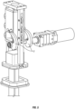
- the present disclosure provides for an impacting apparatus 1000.
- the apparatus comprises a power source, a motor 1, a control circuit 2, a drive mechanism 4, a spring anvil assembly, a striker 5, a pusher plate 6, and at least one bumper 7.
- the spring anvil assembly comprises a gas spring 10 and an anvil 13.
- the gas spring 10 includes a piston 8 that is at least partially disposed within the spring anvil assembly.
- the spring anvil assembly is operatively coupled to the drive mechanism 4.
- a bumper 9 is preferably disposed within the gas spring to absorb a portion of the force of impact of the piston.
- the gas spring 10 may further comprise a nose portion (which nose portion may be a part of or coupled to the piston) and which nose portion makes operative contact with the pusher plate 6 during a portion of the operating cycle.
- the spring anvil assembly comprises a spring without a piston (such as, but not limited to, a mechanical spring or an elastomer) and an anvil 13.
- the drive mechanism may comprise, in an embodiment, a rack gear with intervals of teeth and no teeth, or in an embodiment, a cam driven mechanism as shown in the figures.
- the drive mechanism is configured to permit effectively instantaneous transition from when the gear teeth are engaged to when there is no tooth engagement.
- the drive mechanism is operatively coupled to the spring anvil assembly, such that the drive mechanism may alternate in actuating the spring anvil assembly, thereby actuating the piston (when the gear teeth or cam is engaged, for example) or, in another embodiment, actuating and compressing the spring of the spring anvil assembly, and in withholding a drive force on the spring anvil assembly such that other forces are able to act on and actuate the piston or spring.
- the drive mechanism engages the spring anvil assembly and actuates the piston by pushing it against the pusher plate to store potential energy within the gas spring.
- the initial pressure (before the drive mechanism actuates the piston) within the gas spring assembly is at least 275.79 kPa (40 psia).
- the configuration and design of the gas spring are such that the pressure increase during the piston movement is less than 30% of the initial pressure, thus yielding a more constant torque to the motor that improves the motor efficiency.
- the drive mechanism engages the spring anvil assembly and actuates the spring by pushing it against the pusher plate or by otherwise compressing the spring to store potential energy within the spring.
- the drive mechanism thereafter disengages the spring anvil assembly, allowing pressure or other forces to act on4he the piston and/or spring and cause the piston and/or spring to separate and launch the spring anvil away from the pusher plate and drive the anvil away from the pusher plate.
- the drive mechanism is tuned to prevent further engagement until after the spring anvil assembly has returned to an approximate starting position.
- the drive mechanism may thereafter again act on the spring anvil assembly to again store potential energy within the gas spring and/or spring and may thereafter again temporarily cease to act on the spring anvil assembly to allow potential energy to instead act on the piston and/or spring that has been pushing against the pusher plate (or which spring has been compressed) to launch the spring anvil assembly.
- the drive mechanism is preferably configured to allow for continuous impacting, by way of the cam, for example (as shown in the figures), to provide for such continuous impacting.
- the stroke of the piston is less than the stroke of the spring anvil assembly.
- the spring anvil assembly is operatively coupled to the gas spring, such as to the piston or nose portion such that when the spring anvil assembly is released under pressure the force from the piston is imparted onto the spring anvil assembly, causing the spring anvil assembly to move in a direction and to release (or be launched) away from the pusher plate and impact a striker of the apparatus, which striker transmits the force of the impact to an impact target, such as a post, nail, or rivet, for example.
- the spring anvil assembly comprises a spring without a piston
- the force from the spring is imparter onto the spring anvil assembly, causing the spring anvil assembly to move in a direction and to release (or be launched) away from the pusher plate and impact a striker of the apparatus, which striker transmits the force of the impact to an impact target, such as a post, nail, or rivet, for example.
- the striker facilitates positioning of the impact target so that the impact target can receive the force of the striker and so that the impact target can remain in a position to receive such force when the apparatus is providing multiple or continuous impacts.
- the ratio of the thrown mass to the moving mass within the gas spring was important to the efficiency of the apparatus. It is preferred to have the thrown mass (which in this case is the anvil assembly) greater than 50% of the total moving mass (which is the anvil assembly mass + the gas spring moving mass), and more preferable to have the anvil assembly mass at least 60% of the total moving mass. This allows the present disclosure to have increased efficiency in transferring the potential energy into driving energy on the object or substrate.
- the mass of the spring anvil assembly is two to four times the mass of the gas spring.
- the gas spring piston has a mass of 90 grams and the anvil has a mass of 250 grams.
- the gas spring piston is hollowed out to lighten its mass and further may be constructed of lightweight materials such as hard anodized aluminum, plastics or the like.
- the spring anvil assembly may be operatively coupled to a guide, shaft, or other structure that limits its range of motion.
- At least one bumper is disposed on the apparatus for absorbing a portion of the force of impact of the piston within the gas spring and/or against the anvil, to reduce wear and tear on the components of the apparatus.
- the at least one bumper may be of an elastic material, and may be disposed on the apparatus at any position where it is capable of absorbing a portion of the force of impact by the piston or the anvil.
- the spring anvil assembly further comprises a return mechanism 16 to enable the spring anvil assembly to return to its initial position.
- the return mechanism is a return spring that is disposed on or in the guide or shaft that constrains the spring anvil assembly, which return spring would be disposed nearer the end or portion of anvil that is distal to the gas spring.
- the spring may be disposed with respect to the spring anvil assembly such that motion of the anvil toward an impact target also causes the spring to compress, and after the spring anvil assembly has reached the end of its driven stroke, the compressed spring decompresses to actuate the spring anvil assembly to the spring anvil assemblies earlier or original position.
- An alternate embodiment for returning the spring anvil assembly to its cycle start position is to use the force of the impact target (such as a post, spike, nail or rivet) to bring the spring anvil assembly into its starting position.
- the return mechanism described above is omitted, and the spring anvil assembly is disposed in the down position (i.e., distal to the pusher plate) and rests atop the striker, before the operational cycle commences.
- the operational cycle is unable to commence, which improves the safety profile of the apparatus.
- the striker is placed into contact with the impact target, and the weight of the apparatus or force applied to the tool by the user, causes the striker and the spring anvil assembly to be moved and disposed proximate to the pusher plate (i.e., the starting position of operational cycle, where the spring anvil assembly may be acted upon by the drive mechanism.)
- the striker can also be spring loaded away from the spring anvil assembly further adding to the safety of the tool.
- This embodiment has several advantages. The first is that it would make it less likely to dry fire the apparatus as the apparatus must be in contact with the impact target to be able to operate. The second advantage is that no return mechanism would be required to reset the mechanism, thus eliminating an item that may otherwise wear during use of the apparatus.
- the impact target is utilized to move (push) the spring anvil assembly into position against the pusher plate.
- a stop within the apparatus may also be provided for preventing the impact target or striker from moving with the spring anvil assembly as it is energized. In this position the impact target would rest inside or against the striker and the striker would rest against a stop, preventing the impact target from moving up with the spring anvil assembly when the piston is being actuated to store potential energy within the gas spring. This allows the spring anvil assembly to still release from the pusher plate and re-engage the striker during the drive portion of the operational cycle.
- the apparatus further comprises a power adjustment mechanism for adjusting the force of impact by the apparatus.
- the power adjustment mechanism comprises adjustable positioning of the pusher plate with respect to the spring anvil assembly. By changing such positioning of the pusher plate, the amount of compression of the spring of the spring anvil assembly can be adjusted, and force of impact is consequently adjusted by changing the amount of compression of the spring.
- the position of the pusher plate may be adjusted by way of a screw that may be actuated to reposition the pusher plate or by disposing the pusher plate on a slider, which slider may allow the pusher plate to be repositioned.
- the power adjustment mechanism comprises an adjustment mechanism within the spring anvil assembly that allows changing the compression of the spring of the spring anvil assembly.
- the gas spring is capable of generating a relatively high amount of force in a small amount of space such that the size of the apparatus may be smaller than other impacting apparatuses. Further, because of the relatively small increase from the initial pressure in the gas spring to the maximum pressure, the motor of the apparatus is not significantly overworked or overtorqued, thus leading to a longer useful life of the apparatus. Furthermore, the apparatus disclosed herein has an improved safety profile over prior art impacting devices. For example, the apparatus disclosed herein has an improved recoil force as opposed to the prior art.
- anvil/anvil assembly of the present disclosure is a free traveling mass and, as such, during the course of the driving of an object or striking a substrate, therefore does not put a reactionary force on the operator.
- air pressure on the piston and anvil assembly acts during the entire drive and at the end of the stroke can result in significant recoil to the operator.
Landscapes
- Engineering & Computer Science (AREA)
- Mechanical Engineering (AREA)
- Civil Engineering (AREA)
- Fluid Mechanics (AREA)
- Architecture (AREA)
- Structural Engineering (AREA)
- Physics & Mathematics (AREA)
- Mining & Mineral Resources (AREA)
- Paleontology (AREA)
- General Engineering & Computer Science (AREA)
- General Life Sciences & Earth Sciences (AREA)
- Life Sciences & Earth Sciences (AREA)
- Portable Nailing Machines And Staplers (AREA)
Claims (4)
- Schlagvorrichtung (1000), wobei die Vorrichtung umfassteine Energiequelle,eine Steuerschaltung (2),einen Motor (1),eine Federambossbaugruppe, wobei die Federambossbaugruppe eine Feder (10) und einen Amboss (13) umfasst,einem Schlagbolzen (5),ein geschlagenes Objekt,einen Rückstellmechanismus (16), der eine Führungseinrichtung zum Festhalten der Federambossbaugruppe und des Schlagbolzens (5) umfasst,einen Antriebsmechanismus (4), der die Federambossbaugruppe selektiv in Eingriff nehmen und sich davon lösen kann, wobei der Antriebsmechanismus (4) die Federambossbaugruppe selektiv in Eingriff nehmen und sich danach von der Federambossbaugruppe lösen kann, um die Anwendung einer Kraft auf die Federambossbaugruppe zu beenden,wobei, wenn der Antriebsmechanismus (4) mit der Federambossbaugruppe in Eingriff tritt, potenzielle Energie in der Feder (10) gespeichert wird, und wenn sich der Antriebsmechanismus (4) danach von der Federambossbaugruppe löst, die Feder (10) ihre potenzielle Energie freigibt und die Federambossbaugruppe beschleunigt, wobei sich die Federambossbaugruppe für zumindest einen Teil des Antriebshubs in einem Zustand des freien Flugs befindet, bevor sie auf den Schlagbolzen (5) auftrifft,wobei der Schlagbolzen (5) mit dem geschlagenen Objekt in Kontakt steht, um die Schlagenergie von der Federambossbaugruppe auf das geschlagene Objekt zu übertragen, undwobei die Federambossbaugruppe durch eines von dem geschlagenen Objekt und dem Gewicht der Vorrichtung in eine Startposition vorgespannt wird.
- Vorrichtung nach Anspruch 1, wobei die Federambossbaugruppe ferner einen Kolben (8) umfasst.
- Vorrichtung nach Anspruch 1, wobei die Vorrichtung ferner eine Schubplatte (6) umfasst,
wobei die Federambossbaugruppe während eines Teils des Betriebszyklus der Vorrichtung auf die Schubplatte (6) einwirkt, um die Feder (10) der Federambossbaugruppe zusammenzudrücken, und wobei die Federambossbaugruppe aufhört, auf die Schubplatte (6) einzuwirken, bevor der Amboss auf den Schlagbolzen (5) auftrifft. - Vorrichtung nach Anspruch 3, wobei die Vorrichtung ferner einen Krafteinstellmechanismus zum Einstellen der Schlagkraft der Vorrichtung umfasst, wobei der Krafteinstellmechanismus eine von einer Einstellung der Position der Schubplatte (6) und einer Einstellung des Kompressionsgrads der Feder (10) der Federambossbaugruppe umfasst.
Applications Claiming Priority (2)
| Application Number | Priority Date | Filing Date | Title |
|---|---|---|---|
| US15/402,198 US10751865B2 (en) | 2016-01-08 | 2017-01-09 | Impacting apparatus |
| PCT/US2017/066256 WO2018128765A1 (en) | 2017-01-09 | 2017-12-14 | Impacting apparatus |
Publications (3)
| Publication Number | Publication Date |
|---|---|
| EP3565689A1 EP3565689A1 (de) | 2019-11-13 |
| EP3565689A4 EP3565689A4 (de) | 2020-08-26 |
| EP3565689B1 true EP3565689B1 (de) | 2024-12-11 |
Family
ID=62791318
Family Applications (1)
| Application Number | Title | Priority Date | Filing Date |
|---|---|---|---|
| EP17890017.1A Active EP3565689B1 (de) | 2017-01-09 | 2017-12-14 | Schlagvorrichtung |
Country Status (5)
| Country | Link |
|---|---|
| EP (1) | EP3565689B1 (de) |
| CN (1) | CN110678298B (de) |
| AU (1) | AU2017390178B2 (de) |
| CA (1) | CA3049715C (de) |
| WO (1) | WO2018128765A1 (de) |
Families Citing this family (7)
| Publication number | Priority date | Publication date | Assignee | Title |
|---|---|---|---|---|
| WO2021225770A1 (en) * | 2020-05-05 | 2021-11-11 | Tricord Solutions, Inc. | Fastener driving apparatus |
| US11819989B2 (en) | 2020-07-07 | 2023-11-21 | Techtronic Cordless Gp | Powered fastener driver |
| CN111852174B (zh) * | 2020-07-20 | 2021-12-17 | 台州市黄岩博涛塑业有限公司 | 一种利用惯性加速的磁力加热踩踏式围栏板底座 |
| WO2022079495A1 (en) * | 2020-10-13 | 2022-04-21 | Pranil Wasudeo Tiwaskar | A demolition hammer |
| US12193718B2 (en) | 2021-04-09 | 2025-01-14 | Smith & Nephew, Inc. | Orthopedic surgical instrument |
| CA3167425A1 (en) | 2021-07-16 | 2023-01-16 | Techtronic Cordless Gp | Powered fastener driver |
| GB202312097D0 (en) * | 2023-08-08 | 2023-09-20 | Harvey Engineering 2020 Ltd | Pile driver |
Citations (1)
| Publication number | Priority date | Publication date | Assignee | Title |
|---|---|---|---|---|
| EP1887167A2 (de) * | 2006-08-10 | 2008-02-13 | Joseph Anthony Brennan | Verbesserungen bei und im Zusammenhang mit Pfahlrammen |
Family Cites Families (6)
| Publication number | Priority date | Publication date | Assignee | Title |
|---|---|---|---|---|
| US7004368B1 (en) * | 2004-12-03 | 2006-02-28 | Panrex Industrial Co., Ltd. | Nailing gun having improved nail pusher |
| CN100577367C (zh) * | 2006-10-23 | 2010-01-06 | 吴纯培 | 直线冲击装置 |
| EP2243600B1 (de) * | 2007-10-05 | 2015-11-25 | Senco Brands, Inc | Eintreibwerkzeug mit Gasfeder für Befestigungsmittel und Verfahren für die Werkzeugkontrolle |
| DE102012210082A1 (de) * | 2012-06-15 | 2013-12-19 | Hilti Aktiengesellschaft | Werkzeugmaschine und Steuerungsverfahren |
| US10065300B2 (en) * | 2014-10-07 | 2018-09-04 | Tricord Solutions, Inc. | Fastener driving apparatus |
| EP3253534B1 (de) * | 2015-02-06 | 2020-05-06 | Milwaukee Electric Tool Corporation | Gasfederbetriebener befestigungstreiber |
-
2017
- 2017-12-14 CN CN201780087886.XA patent/CN110678298B/zh active Active
- 2017-12-14 WO PCT/US2017/066256 patent/WO2018128765A1/en not_active Ceased
- 2017-12-14 AU AU2017390178A patent/AU2017390178B2/en active Active
- 2017-12-14 CA CA3049715A patent/CA3049715C/en active Active
- 2017-12-14 EP EP17890017.1A patent/EP3565689B1/de active Active
Patent Citations (1)
| Publication number | Priority date | Publication date | Assignee | Title |
|---|---|---|---|---|
| EP1887167A2 (de) * | 2006-08-10 | 2008-02-13 | Joseph Anthony Brennan | Verbesserungen bei und im Zusammenhang mit Pfahlrammen |
Also Published As
| Publication number | Publication date |
|---|---|
| EP3565689A1 (de) | 2019-11-13 |
| AU2017390178B2 (en) | 2024-02-08 |
| CA3049715A1 (en) | 2018-07-12 |
| WO2018128765A1 (en) | 2018-07-12 |
| EP3565689A4 (de) | 2020-08-26 |
| CA3049715C (en) | 2022-10-04 |
| AU2017390178A1 (en) | 2019-07-25 |
| CN110678298A (zh) | 2020-01-10 |
| CN110678298B (zh) | 2023-05-16 |
Similar Documents
| Publication | Publication Date | Title |
|---|---|---|
| EP3565689B1 (de) | Schlagvorrichtung | |
| US10751865B2 (en) | Impacting apparatus | |
| US10065300B2 (en) | Fastener driving apparatus | |
| US9962821B2 (en) | Fastener driving apparatus | |
| US9539714B1 (en) | Fastener driving apparatus | |
| US9636812B2 (en) | Fastener driving apparatus | |
| AU2002357916B2 (en) | Enhanced electrical motor driven nail gun | |
| EP2768632B1 (de) | Gerät zum eintreiben eines befestigungselements | |
| US20170274513A1 (en) | Fastener driving apparatus | |
| US9555530B2 (en) | Fastener driving apparatus | |
| US8939341B2 (en) | Fastener driving apparatus | |
| US20060180631A1 (en) | Electric motor driven energy storage device for impacting | |
| US20040232194A1 (en) | Enhanced electrical motor driven nail gun | |
| US20190224825A1 (en) | Gas spring and impacting and driving apparatus with gas spring | |
| US11292114B2 (en) | Fastener driving apparatus | |
| US20180193993A1 (en) | Compact Impacting Apparatus | |
| CA2993187C (en) | Fastener driving apparatus | |
| US20230226676A1 (en) | Fastener Driving Apparatus | |
| US10974378B2 (en) | Fastener driving apparatus | |
| US20240408734A1 (en) | Impacting Apparatus | |
| NZ531817A (en) | Enhanced electrical motor driven nail gun |
Legal Events
| Date | Code | Title | Description |
|---|---|---|---|
| STAA | Information on the status of an ep patent application or granted ep patent |
Free format text: STATUS: THE INTERNATIONAL PUBLICATION HAS BEEN MADE |
|
| PUAI | Public reference made under article 153(3) epc to a published international application that has entered the european phase |
Free format text: ORIGINAL CODE: 0009012 |
|
| STAA | Information on the status of an ep patent application or granted ep patent |
Free format text: STATUS: REQUEST FOR EXAMINATION WAS MADE |
|
| 17P | Request for examination filed |
Effective date: 20190709 |
|
| AK | Designated contracting states |
Kind code of ref document: A1 Designated state(s): AL AT BE BG CH CY CZ DE DK EE ES FI FR GB GR HR HU IE IS IT LI LT LU LV MC MK MT NL NO PL PT RO RS SE SI SK SM TR |
|
| AX | Request for extension of the european patent |
Extension state: BA ME |
|
| DAV | Request for validation of the european patent (deleted) | ||
| DAX | Request for extension of the european patent (deleted) | ||
| A4 | Supplementary search report drawn up and despatched |
Effective date: 20200729 |
|
| RIC1 | Information provided on ipc code assigned before grant |
Ipc: B25D 9/04 20060101ALI20200723BHEP Ipc: E04H 17/26 20060101ALI20200723BHEP Ipc: B25C 1/04 20060101ALI20200723BHEP Ipc: B25D 1/16 20060101ALI20200723BHEP Ipc: B25D 17/06 20060101ALI20200723BHEP Ipc: B25C 1/06 20060101ALI20200723BHEP Ipc: B25D 9/08 20060101AFI20200723BHEP |
|
| STAA | Information on the status of an ep patent application or granted ep patent |
Free format text: STATUS: EXAMINATION IS IN PROGRESS |
|
| 17Q | First examination report despatched |
Effective date: 20221208 |
|
| GRAP | Despatch of communication of intention to grant a patent |
Free format text: ORIGINAL CODE: EPIDOSNIGR1 |
|
| STAA | Information on the status of an ep patent application or granted ep patent |
Free format text: STATUS: GRANT OF PATENT IS INTENDED |
|
| INTG | Intention to grant announced |
Effective date: 20240207 |
|
| GRAJ | Information related to disapproval of communication of intention to grant by the applicant or resumption of examination proceedings by the epo deleted |
Free format text: ORIGINAL CODE: EPIDOSDIGR1 |
|
| STAA | Information on the status of an ep patent application or granted ep patent |
Free format text: STATUS: EXAMINATION IS IN PROGRESS |
|
| GRAS | Grant fee paid |
Free format text: ORIGINAL CODE: EPIDOSNIGR3 |
|
| STAA | Information on the status of an ep patent application or granted ep patent |
Free format text: STATUS: GRANT OF PATENT IS INTENDED |
|
| GRAP | Despatch of communication of intention to grant a patent |
Free format text: ORIGINAL CODE: EPIDOSNIGR1 |
|
| INTC | Intention to grant announced (deleted) | ||
| RAP3 | Party data changed (applicant data changed or rights of an application transferred) |
Owner name: TRICORD SOLUTIONS, INC. |
|
| RIN1 | Information on inventor provided before grant (corrected) |
Inventor name: WITZIGREUTER, JOHN Inventor name: PEDICINI, CHRISTOPHER |
|
| INTG | Intention to grant announced |
Effective date: 20240705 |
|
| GRAA | (expected) grant |
Free format text: ORIGINAL CODE: 0009210 |
|
| STAA | Information on the status of an ep patent application or granted ep patent |
Free format text: STATUS: THE PATENT HAS BEEN GRANTED |
|
| AK | Designated contracting states |
Kind code of ref document: B1 Designated state(s): AL AT BE BG CH CY CZ DE DK EE ES FI FR GB GR HR HU IE IS IT LI LT LU LV MC MK MT NL NO PL PT RO RS SE SI SK SM TR |
|
| REG | Reference to a national code |
Ref country code: GB Ref legal event code: FG4D |
|
| REG | Reference to a national code |
Ref country code: CH Ref legal event code: EP |
|
| REG | Reference to a national code |
Ref country code: DE Ref legal event code: R096 Ref document number: 602017086760 Country of ref document: DE |
|
| REG | Reference to a national code |
Ref country code: IE Ref legal event code: FG4D |
|
| REG | Reference to a national code |
Ref country code: LT Ref legal event code: MG9D |
|
| PG25 | Lapsed in a contracting state [announced via postgrant information from national office to epo] |
Ref country code: HR Free format text: LAPSE BECAUSE OF FAILURE TO SUBMIT A TRANSLATION OF THE DESCRIPTION OR TO PAY THE FEE WITHIN THE PRESCRIBED TIME-LIMIT Effective date: 20241211 |
|
| PG25 | Lapsed in a contracting state [announced via postgrant information from national office to epo] |
Ref country code: FI Free format text: LAPSE BECAUSE OF FAILURE TO SUBMIT A TRANSLATION OF THE DESCRIPTION OR TO PAY THE FEE WITHIN THE PRESCRIBED TIME-LIMIT Effective date: 20241211 |
|
| PG25 | Lapsed in a contracting state [announced via postgrant information from national office to epo] |
Ref country code: BG Free format text: LAPSE BECAUSE OF FAILURE TO SUBMIT A TRANSLATION OF THE DESCRIPTION OR TO PAY THE FEE WITHIN THE PRESCRIBED TIME-LIMIT Effective date: 20241211 |
|
| REG | Reference to a national code |
Ref country code: NL Ref legal event code: MP Effective date: 20241211 |
|
| PG25 | Lapsed in a contracting state [announced via postgrant information from national office to epo] |
Ref country code: ES Free format text: LAPSE BECAUSE OF FAILURE TO SUBMIT A TRANSLATION OF THE DESCRIPTION OR TO PAY THE FEE WITHIN THE PRESCRIBED TIME-LIMIT Effective date: 20241211 |
|
| PG25 | Lapsed in a contracting state [announced via postgrant information from national office to epo] |
Ref country code: NO Free format text: LAPSE BECAUSE OF FAILURE TO SUBMIT A TRANSLATION OF THE DESCRIPTION OR TO PAY THE FEE WITHIN THE PRESCRIBED TIME-LIMIT Effective date: 20250311 |
|
| PG25 | Lapsed in a contracting state [announced via postgrant information from national office to epo] |
Ref country code: LV Free format text: LAPSE BECAUSE OF FAILURE TO SUBMIT A TRANSLATION OF THE DESCRIPTION OR TO PAY THE FEE WITHIN THE PRESCRIBED TIME-LIMIT Effective date: 20241211 Ref country code: GR Free format text: LAPSE BECAUSE OF FAILURE TO SUBMIT A TRANSLATION OF THE DESCRIPTION OR TO PAY THE FEE WITHIN THE PRESCRIBED TIME-LIMIT Effective date: 20250312 |
|
| PG25 | Lapsed in a contracting state [announced via postgrant information from national office to epo] |
Ref country code: RS Free format text: LAPSE BECAUSE OF FAILURE TO SUBMIT A TRANSLATION OF THE DESCRIPTION OR TO PAY THE FEE WITHIN THE PRESCRIBED TIME-LIMIT Effective date: 20250311 |
|
| PG25 | Lapsed in a contracting state [announced via postgrant information from national office to epo] |
Ref country code: NL Free format text: LAPSE BECAUSE OF FAILURE TO SUBMIT A TRANSLATION OF THE DESCRIPTION OR TO PAY THE FEE WITHIN THE PRESCRIBED TIME-LIMIT Effective date: 20241211 |
|
| REG | Reference to a national code |
Ref country code: AT Ref legal event code: MK05 Ref document number: 1750034 Country of ref document: AT Kind code of ref document: T Effective date: 20241211 |
|
| PG25 | Lapsed in a contracting state [announced via postgrant information from national office to epo] |
Ref country code: SM Free format text: LAPSE BECAUSE OF FAILURE TO SUBMIT A TRANSLATION OF THE DESCRIPTION OR TO PAY THE FEE WITHIN THE PRESCRIBED TIME-LIMIT Effective date: 20241211 |
|
| PG25 | Lapsed in a contracting state [announced via postgrant information from national office to epo] |
Ref country code: PL Free format text: LAPSE BECAUSE OF FAILURE TO SUBMIT A TRANSLATION OF THE DESCRIPTION OR TO PAY THE FEE WITHIN THE PRESCRIBED TIME-LIMIT Effective date: 20241211 |
|
| PG25 | Lapsed in a contracting state [announced via postgrant information from national office to epo] |
Ref country code: IS Free format text: LAPSE BECAUSE OF FAILURE TO SUBMIT A TRANSLATION OF THE DESCRIPTION OR TO PAY THE FEE WITHIN THE PRESCRIBED TIME-LIMIT Effective date: 20250411 |
|
| PG25 | Lapsed in a contracting state [announced via postgrant information from national office to epo] |
Ref country code: PT Free format text: LAPSE BECAUSE OF FAILURE TO SUBMIT A TRANSLATION OF THE DESCRIPTION OR TO PAY THE FEE WITHIN THE PRESCRIBED TIME-LIMIT Effective date: 20250411 |
|
| PG25 | Lapsed in a contracting state [announced via postgrant information from national office to epo] |
Ref country code: EE Free format text: LAPSE BECAUSE OF FAILURE TO SUBMIT A TRANSLATION OF THE DESCRIPTION OR TO PAY THE FEE WITHIN THE PRESCRIBED TIME-LIMIT Effective date: 20241211 |
|
| PG25 | Lapsed in a contracting state [announced via postgrant information from national office to epo] |
Ref country code: RO Free format text: LAPSE BECAUSE OF FAILURE TO SUBMIT A TRANSLATION OF THE DESCRIPTION OR TO PAY THE FEE WITHIN THE PRESCRIBED TIME-LIMIT Effective date: 20241211 Ref country code: AT Free format text: LAPSE BECAUSE OF FAILURE TO SUBMIT A TRANSLATION OF THE DESCRIPTION OR TO PAY THE FEE WITHIN THE PRESCRIBED TIME-LIMIT Effective date: 20241211 |
|
| PG25 | Lapsed in a contracting state [announced via postgrant information from national office to epo] |
Ref country code: SK Free format text: LAPSE BECAUSE OF FAILURE TO SUBMIT A TRANSLATION OF THE DESCRIPTION OR TO PAY THE FEE WITHIN THE PRESCRIBED TIME-LIMIT Effective date: 20241211 |
|
| PG25 | Lapsed in a contracting state [announced via postgrant information from national office to epo] |
Ref country code: CZ Free format text: LAPSE BECAUSE OF FAILURE TO SUBMIT A TRANSLATION OF THE DESCRIPTION OR TO PAY THE FEE WITHIN THE PRESCRIBED TIME-LIMIT Effective date: 20241211 |
|
| PG25 | Lapsed in a contracting state [announced via postgrant information from national office to epo] |
Ref country code: IT Free format text: LAPSE BECAUSE OF FAILURE TO SUBMIT A TRANSLATION OF THE DESCRIPTION OR TO PAY THE FEE WITHIN THE PRESCRIBED TIME-LIMIT Effective date: 20241211 |
|
| REG | Reference to a national code |
Ref country code: CH Ref legal event code: PL |
|
| PG25 | Lapsed in a contracting state [announced via postgrant information from national office to epo] |
Ref country code: LU Free format text: LAPSE BECAUSE OF NON-PAYMENT OF DUE FEES Effective date: 20241214 |
|
| PG25 | Lapsed in a contracting state [announced via postgrant information from national office to epo] |
Ref country code: SE Free format text: LAPSE BECAUSE OF FAILURE TO SUBMIT A TRANSLATION OF THE DESCRIPTION OR TO PAY THE FEE WITHIN THE PRESCRIBED TIME-LIMIT Effective date: 20241211 |
|
| REG | Reference to a national code |
Ref country code: DE Ref legal event code: R097 Ref document number: 602017086760 Country of ref document: DE |
|
| PG25 | Lapsed in a contracting state [announced via postgrant information from national office to epo] |
Ref country code: MC Free format text: LAPSE BECAUSE OF FAILURE TO SUBMIT A TRANSLATION OF THE DESCRIPTION OR TO PAY THE FEE WITHIN THE PRESCRIBED TIME-LIMIT Effective date: 20241211 |
|
| REG | Reference to a national code |
Ref country code: BE Ref legal event code: MM Effective date: 20241231 |
|
| PG25 | Lapsed in a contracting state [announced via postgrant information from national office to epo] |
Ref country code: DK Free format text: LAPSE BECAUSE OF FAILURE TO SUBMIT A TRANSLATION OF THE DESCRIPTION OR TO PAY THE FEE WITHIN THE PRESCRIBED TIME-LIMIT Effective date: 20241211 |
|
| PG25 | Lapsed in a contracting state [announced via postgrant information from national office to epo] |
Ref country code: BE Free format text: LAPSE BECAUSE OF NON-PAYMENT OF DUE FEES Effective date: 20241231 |
|
| PLBE | No opposition filed within time limit |
Free format text: ORIGINAL CODE: 0009261 |
|
| STAA | Information on the status of an ep patent application or granted ep patent |
Free format text: STATUS: NO OPPOSITION FILED WITHIN TIME LIMIT |
|
| PG25 | Lapsed in a contracting state [announced via postgrant information from national office to epo] |
Ref country code: CH Free format text: LAPSE BECAUSE OF NON-PAYMENT OF DUE FEES Effective date: 20241231 |
|
| PG25 | Lapsed in a contracting state [announced via postgrant information from national office to epo] |
Ref country code: IE Free format text: LAPSE BECAUSE OF NON-PAYMENT OF DUE FEES Effective date: 20241214 |
|
| 26N | No opposition filed |
Effective date: 20250912 |
|
| PGFP | Annual fee paid to national office [announced via postgrant information from national office to epo] |
Ref country code: DE Payment date: 20251113 Year of fee payment: 9 |
|
| PGFP | Annual fee paid to national office [announced via postgrant information from national office to epo] |
Ref country code: GB Payment date: 20251121 Year of fee payment: 9 |
|
| PGFP | Annual fee paid to national office [announced via postgrant information from national office to epo] |
Ref country code: FR Payment date: 20251118 Year of fee payment: 9 |