EP1886007B1 - Air-fuel ratio control apparatus for internal combustion engine - Google Patents
Air-fuel ratio control apparatus for internal combustion engine Download PDFInfo
- Publication number
- EP1886007B1 EP1886007B1 EP06746577A EP06746577A EP1886007B1 EP 1886007 B1 EP1886007 B1 EP 1886007B1 EP 06746577 A EP06746577 A EP 06746577A EP 06746577 A EP06746577 A EP 06746577A EP 1886007 B1 EP1886007 B1 EP 1886007B1
- Authority
- EP
- European Patent Office
- Prior art keywords
- air
- fuel ratio
- cylinder
- exhaust
- fuel
- Prior art date
- Legal status (The legal status is an assumption and is not a legal conclusion. Google has not performed a legal analysis and makes no representation as to the accuracy of the status listed.)
- Ceased
Links
Images


Classifications
-
- F—MECHANICAL ENGINEERING; LIGHTING; HEATING; WEAPONS; BLASTING
- F02—COMBUSTION ENGINES; HOT-GAS OR COMBUSTION-PRODUCT ENGINE PLANTS
- F02D—CONTROLLING COMBUSTION ENGINES
- F02D41/00—Electrical control of supply of combustible mixture or its constituents
- F02D41/008—Controlling each cylinder individually
- F02D41/0082—Controlling each cylinder individually per groups or banks
-
- F—MECHANICAL ENGINEERING; LIGHTING; HEATING; WEAPONS; BLASTING
- F01—MACHINES OR ENGINES IN GENERAL; ENGINE PLANTS IN GENERAL; STEAM ENGINES
- F01N—GAS-FLOW SILENCERS OR EXHAUST APPARATUS FOR MACHINES OR ENGINES IN GENERAL; GAS-FLOW SILENCERS OR EXHAUST APPARATUS FOR INTERNAL-COMBUSTION ENGINES
- F01N11/00—Monitoring or diagnostic devices for exhaust-gas treatment apparatus
- F01N11/007—Monitoring or diagnostic devices for exhaust-gas treatment apparatus the diagnostic devices measuring oxygen or air concentration downstream of the exhaust apparatus
-
- F—MECHANICAL ENGINEERING; LIGHTING; HEATING; WEAPONS; BLASTING
- F01—MACHINES OR ENGINES IN GENERAL; ENGINE PLANTS IN GENERAL; STEAM ENGINES
- F01N—GAS-FLOW SILENCERS OR EXHAUST APPARATUS FOR MACHINES OR ENGINES IN GENERAL; GAS-FLOW SILENCERS OR EXHAUST APPARATUS FOR INTERNAL-COMBUSTION ENGINES
- F01N13/00—Exhaust or silencing apparatus characterised by constructional features
- F01N13/009—Exhaust or silencing apparatus characterised by constructional features having two or more separate purifying devices arranged in series
-
- F—MECHANICAL ENGINEERING; LIGHTING; HEATING; WEAPONS; BLASTING
- F01—MACHINES OR ENGINES IN GENERAL; ENGINE PLANTS IN GENERAL; STEAM ENGINES
- F01N—GAS-FLOW SILENCERS OR EXHAUST APPARATUS FOR MACHINES OR ENGINES IN GENERAL; GAS-FLOW SILENCERS OR EXHAUST APPARATUS FOR INTERNAL-COMBUSTION ENGINES
- F01N13/00—Exhaust or silencing apparatus characterised by constructional features
- F01N13/011—Exhaust or silencing apparatus characterised by constructional features having two or more purifying devices arranged in parallel
-
- F—MECHANICAL ENGINEERING; LIGHTING; HEATING; WEAPONS; BLASTING
- F01—MACHINES OR ENGINES IN GENERAL; ENGINE PLANTS IN GENERAL; STEAM ENGINES
- F01N—GAS-FLOW SILENCERS OR EXHAUST APPARATUS FOR MACHINES OR ENGINES IN GENERAL; GAS-FLOW SILENCERS OR EXHAUST APPARATUS FOR INTERNAL-COMBUSTION ENGINES
- F01N13/00—Exhaust or silencing apparatus characterised by constructional features
- F01N13/08—Other arrangements or adaptations of exhaust conduits
- F01N13/10—Other arrangements or adaptations of exhaust conduits of exhaust manifolds
- F01N13/107—More than one exhaust manifold or exhaust collector
-
- F—MECHANICAL ENGINEERING; LIGHTING; HEATING; WEAPONS; BLASTING
- F01—MACHINES OR ENGINES IN GENERAL; ENGINE PLANTS IN GENERAL; STEAM ENGINES
- F01N—GAS-FLOW SILENCERS OR EXHAUST APPARATUS FOR MACHINES OR ENGINES IN GENERAL; GAS-FLOW SILENCERS OR EXHAUST APPARATUS FOR INTERNAL-COMBUSTION ENGINES
- F01N3/00—Exhaust or silencing apparatus having means for purifying, rendering innocuous, or otherwise treating exhaust
- F01N3/08—Exhaust or silencing apparatus having means for purifying, rendering innocuous, or otherwise treating exhaust for rendering innocuous
- F01N3/0807—Exhaust or silencing apparatus having means for purifying, rendering innocuous, or otherwise treating exhaust for rendering innocuous by using absorbents or adsorbents
- F01N3/0814—Exhaust or silencing apparatus having means for purifying, rendering innocuous, or otherwise treating exhaust for rendering innocuous by using absorbents or adsorbents combined with catalytic converters, e.g. NOx absorption/storage reduction catalysts
-
- F—MECHANICAL ENGINEERING; LIGHTING; HEATING; WEAPONS; BLASTING
- F01—MACHINES OR ENGINES IN GENERAL; ENGINE PLANTS IN GENERAL; STEAM ENGINES
- F01N—GAS-FLOW SILENCERS OR EXHAUST APPARATUS FOR MACHINES OR ENGINES IN GENERAL; GAS-FLOW SILENCERS OR EXHAUST APPARATUS FOR INTERNAL-COMBUSTION ENGINES
- F01N3/00—Exhaust or silencing apparatus having means for purifying, rendering innocuous, or otherwise treating exhaust
- F01N3/08—Exhaust or silencing apparatus having means for purifying, rendering innocuous, or otherwise treating exhaust for rendering innocuous
- F01N3/0807—Exhaust or silencing apparatus having means for purifying, rendering innocuous, or otherwise treating exhaust for rendering innocuous by using absorbents or adsorbents
- F01N3/0828—Exhaust or silencing apparatus having means for purifying, rendering innocuous, or otherwise treating exhaust for rendering innocuous by using absorbents or adsorbents characterised by the absorbed or adsorbed substances
- F01N3/0842—Nitrogen oxides
-
- F—MECHANICAL ENGINEERING; LIGHTING; HEATING; WEAPONS; BLASTING
- F02—COMBUSTION ENGINES; HOT-GAS OR COMBUSTION-PRODUCT ENGINE PLANTS
- F02D—CONTROLLING COMBUSTION ENGINES
- F02D41/00—Electrical control of supply of combustible mixture or its constituents
- F02D41/0002—Controlling intake air
-
- F—MECHANICAL ENGINEERING; LIGHTING; HEATING; WEAPONS; BLASTING
- F02—COMBUSTION ENGINES; HOT-GAS OR COMBUSTION-PRODUCT ENGINE PLANTS
- F02D—CONTROLLING COMBUSTION ENGINES
- F02D41/00—Electrical control of supply of combustible mixture or its constituents
- F02D41/02—Circuit arrangements for generating control signals
- F02D41/021—Introducing corrections for particular conditions exterior to the engine
- F02D41/0235—Introducing corrections for particular conditions exterior to the engine in relation with the state of the exhaust gas treating apparatus
- F02D41/027—Introducing corrections for particular conditions exterior to the engine in relation with the state of the exhaust gas treating apparatus to purge or regenerate the exhaust gas treating apparatus
- F02D41/0275—Introducing corrections for particular conditions exterior to the engine in relation with the state of the exhaust gas treating apparatus to purge or regenerate the exhaust gas treating apparatus the exhaust gas treating apparatus being a NOx trap or adsorbent
- F02D41/028—Desulfurisation of NOx traps or adsorbent
-
- F—MECHANICAL ENGINEERING; LIGHTING; HEATING; WEAPONS; BLASTING
- F01—MACHINES OR ENGINES IN GENERAL; ENGINE PLANTS IN GENERAL; STEAM ENGINES
- F01N—GAS-FLOW SILENCERS OR EXHAUST APPARATUS FOR MACHINES OR ENGINES IN GENERAL; GAS-FLOW SILENCERS OR EXHAUST APPARATUS FOR INTERNAL-COMBUSTION ENGINES
- F01N2430/00—Influencing exhaust purification, e.g. starting of catalytic reaction, filter regeneration, or the like, by controlling engine operating characteristics
- F01N2430/10—Influencing exhaust purification, e.g. starting of catalytic reaction, filter regeneration, or the like, by controlling engine operating characteristics by modifying inlet or exhaust valve timing
-
- F—MECHANICAL ENGINEERING; LIGHTING; HEATING; WEAPONS; BLASTING
- F01—MACHINES OR ENGINES IN GENERAL; ENGINE PLANTS IN GENERAL; STEAM ENGINES
- F01N—GAS-FLOW SILENCERS OR EXHAUST APPARATUS FOR MACHINES OR ENGINES IN GENERAL; GAS-FLOW SILENCERS OR EXHAUST APPARATUS FOR INTERNAL-COMBUSTION ENGINES
- F01N2560/00—Exhaust systems with means for detecting or measuring exhaust gas components or characteristics
- F01N2560/02—Exhaust systems with means for detecting or measuring exhaust gas components or characteristics the means being an exhaust gas sensor
- F01N2560/025—Exhaust systems with means for detecting or measuring exhaust gas components or characteristics the means being an exhaust gas sensor for measuring or detecting O2, e.g. lambda sensors
-
- F—MECHANICAL ENGINEERING; LIGHTING; HEATING; WEAPONS; BLASTING
- F01—MACHINES OR ENGINES IN GENERAL; ENGINE PLANTS IN GENERAL; STEAM ENGINES
- F01N—GAS-FLOW SILENCERS OR EXHAUST APPARATUS FOR MACHINES OR ENGINES IN GENERAL; GAS-FLOW SILENCERS OR EXHAUST APPARATUS FOR INTERNAL-COMBUSTION ENGINES
- F01N2560/00—Exhaust systems with means for detecting or measuring exhaust gas components or characteristics
- F01N2560/14—Exhaust systems with means for detecting or measuring exhaust gas components or characteristics having more than one sensor of one kind
-
- F—MECHANICAL ENGINEERING; LIGHTING; HEATING; WEAPONS; BLASTING
- F02—COMBUSTION ENGINES; HOT-GAS OR COMBUSTION-PRODUCT ENGINE PLANTS
- F02D—CONTROLLING COMBUSTION ENGINES
- F02D41/00—Electrical control of supply of combustible mixture or its constituents
- F02D41/0002—Controlling intake air
- F02D2041/001—Controlling intake air for engines with variable valve actuation
-
- Y—GENERAL TAGGING OF NEW TECHNOLOGICAL DEVELOPMENTS; GENERAL TAGGING OF CROSS-SECTIONAL TECHNOLOGIES SPANNING OVER SEVERAL SECTIONS OF THE IPC; TECHNICAL SUBJECTS COVERED BY FORMER USPC CROSS-REFERENCE ART COLLECTIONS [XRACs] AND DIGESTS
- Y02—TECHNOLOGIES OR APPLICATIONS FOR MITIGATION OR ADAPTATION AGAINST CLIMATE CHANGE
- Y02T—CLIMATE CHANGE MITIGATION TECHNOLOGIES RELATED TO TRANSPORTATION
- Y02T10/00—Road transport of goods or passengers
- Y02T10/10—Internal combustion engine [ICE] based vehicles
- Y02T10/40—Engine management systems
Definitions
- the apparatus according to the first or second aspect of the present invention may further comprise ignition timing control means.
- the ignition timing control means gives ignition timing for optimizing torque and fuel consumption to a cylinder group that performs a rich burn process, and gives ignition timing that is retarded from the ignition timing for optimizing torque and fuel consumption to a cylinder group that performs a lean burn process.
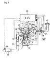
- the cylinder head 8 includes an intake port 20 that communicates with the combustion chamber 16.
- the joint between the intake port 20 and combustion chamber 16 is provided with an intake valve 22.
- a variable valve mechanism 24 is positioned between the intake valve 22 and an intake camshaft 23.
- the intake camshaft 23 is coupled to the crankshaft 12 via a coupling mechanism (not shown).
- the intake port 20 is connected to an intake path 28.
- An injector (also called “fuel injection valve”) 26 is positioned near the intake port 20. The injector 26 injects fuel to an area near the intake port 20.
- a surge tank 30 is positioned in the middle of the intake path 28. As shown in Fig. 2 , a first intake path 28a, which is connected to the cylinders 2 of the first cylinder group 2a, and a second intake path 28b, which is connected to the cylinders 2 of the second cylinder group 2b, communicate with the common surge tank 30.
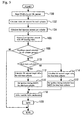
- step 102 is performed to calculate the intake air amount for each cylinder.
- the intake air amount for each cylinder can be calculated from the intake air amount Ga and lift amount that were read in step 100.
- step 110 is performed to judge whether a cylinder belongs to a cylinder group that performs a rich burn process (hereinafter referred to as a "rich burn cylinder"). If the judgment result obtained in step 110 indicates that the cylinder is a rich burn cylinder, that is, the cylinder 2 belongs to the first cylinder group 2a, a map stored in the ECU 60 is referenced to calculate a lift amount target value for the rich burn cylinder (step 112). The map defines the lift amount target value with reference to the relationship between the engine speed NE and engine load KL. Further, the map is formulated so that the lift amount decreases with an increase in the engine speed NE and engine load KL.
- step 144 If the judgment result obtained in step 144 indicates that the air-fuel ratio AF1 is greater than the target value, the fuel injection amounts for the cylinders 2 belonging to the first cylinder group 2a are increased to shift the air-fuel ratio AF1 toward the rich side (step 146). If, on the other hand, the judgment result obtained in step 144 indicates that the air-fuel ratio AF1 is smaller than the target value, the fuel injection amounts for the cylinders 2 belonging to the first cylinder group 2a are decreased to shift the air-fuel ratio AF1 toward the lean side (step 148).
- steps 144 to 148 is also performed for the second cylinder group 2b. More specifically, the fuel injection amounts for the cylinders 2 belonging to the second cylinder group 2b are changed to shift the air-fuel ratio AF2 toward the rich side or lean side.
- the air-fuel ratio sensor 58 for detecting the air-fuel ratio AF3 is positioned downstream of the NOx catalyst 56.
- the air-fuel ratio sensor may be placed in any position as far as it is positioned downstream of the confluence 50c of the first exhaust path 50a and second exhaust path 50b.
- an object of the third embodiment can be achieved if the air-fuel ratio prevailing downstream of the confluence 50c is acquired. Therefore, a calculated value may be read as the air-fuel ratio without having to detect the air-fuel ratio with the sensor.
Landscapes
- Engineering & Computer Science (AREA)
- Chemical & Material Sciences (AREA)
- Combustion & Propulsion (AREA)
- Mechanical Engineering (AREA)
- General Engineering & Computer Science (AREA)
- Chemical Kinetics & Catalysis (AREA)
- Electrical Control Of Air Or Fuel Supplied To Internal-Combustion Engine (AREA)
- Output Control And Ontrol Of Special Type Engine (AREA)
- Combined Controls Of Internal Combustion Engines (AREA)
- Exhaust Gas After Treatment (AREA)
- Electrical Control Of Ignition Timing (AREA)
Applications Claiming Priority (2)
| Application Number | Priority Date | Filing Date | Title |
|---|---|---|---|
| JP2005159778A JP4297082B2 (ja) | 2005-05-31 | 2005-05-31 | 内燃機関の空燃比制御装置 |
| PCT/JP2006/309889 WO2006129483A1 (en) | 2005-05-31 | 2006-05-11 | Air-fuel ratio control apparatus for internal combustion engine |
Publications (2)
| Publication Number | Publication Date |
|---|---|
| EP1886007A1 EP1886007A1 (en) | 2008-02-13 |
| EP1886007B1 true EP1886007B1 (en) | 2012-11-07 |
Family
ID=36691858
Family Applications (1)
| Application Number | Title | Priority Date | Filing Date |
|---|---|---|---|
| EP06746577A Ceased EP1886007B1 (en) | 2005-05-31 | 2006-05-11 | Air-fuel ratio control apparatus for internal combustion engine |
Country Status (5)
| Country | Link |
|---|---|
| US (1) | US7377273B2 (enExample) |
| EP (1) | EP1886007B1 (enExample) |
| JP (1) | JP4297082B2 (enExample) |
| CN (1) | CN100449129C (enExample) |
| WO (1) | WO2006129483A1 (enExample) |
Families Citing this family (20)
| Publication number | Priority date | Publication date | Assignee | Title |
|---|---|---|---|---|
| US6657237B2 (en) | 2000-12-18 | 2003-12-02 | Samsung Electro-Mechanics Co., Ltd. | GaN based group III-V nitride semiconductor light-emitting diode and method for fabricating the same |
| WO2008044390A1 (en) * | 2006-10-12 | 2008-04-17 | Toyota Jidosha Kabushiki Kaisha | Device for controlling air/fuel ratio of multi-cylinder internal combustion engine |
| JP4400633B2 (ja) * | 2007-02-26 | 2010-01-20 | トヨタ自動車株式会社 | 内燃機関の制御システム |
| US7706957B2 (en) * | 2007-08-30 | 2010-04-27 | Denso Corporation | Apparatus for controlling quantity of fuel to be actually sprayed from injector in multiple injection mode |
| JP4470975B2 (ja) * | 2007-08-30 | 2010-06-02 | 株式会社デンソー | 燃料噴射制御装置およびそれを用いた燃料噴射システム |
| JP5411728B2 (ja) * | 2010-01-28 | 2014-02-12 | 本田技研工業株式会社 | 内燃機関の空燃比学習制御装置 |
| JP5411730B2 (ja) * | 2010-01-29 | 2014-02-12 | 本田技研工業株式会社 | 車両用内燃機関の空燃比学習制御装置 |
| US9393954B2 (en) * | 2012-05-04 | 2016-07-19 | Ford Global Technologies, Llc | Methods and systems for engine stopping |
| CN103244291A (zh) * | 2013-04-25 | 2013-08-14 | 天津大学 | 配有NOx吸附还原催化转化器的稀燃汽油机恒扭矩自学习控制方法 |
| CN103216343A (zh) * | 2013-04-25 | 2013-07-24 | 天津大学 | 配有NOx吸附还原催化转化器的稀燃汽油机恒扭矩自学习控制系统 |
| CN103225554A (zh) * | 2013-04-25 | 2013-07-31 | 天津大学 | 配有NOx吸附还原催化转化器的稀燃汽油机恒扭矩自学习控制方法 |
| JP6183295B2 (ja) * | 2014-05-30 | 2017-08-23 | トヨタ自動車株式会社 | 内燃機関の制御装置 |
| JP6287802B2 (ja) * | 2014-12-12 | 2018-03-07 | トヨタ自動車株式会社 | 内燃機関の制御装置 |
| US10077727B2 (en) | 2016-01-13 | 2018-09-18 | GM Global Technology Operations LLC | Engine control systems and methods for nitrogen oxide reduction |
| US9957911B2 (en) * | 2016-02-18 | 2018-05-01 | GM Global Technology Operations LLC | Dedicated exhaust gas recirculation control systems and methods |
| JP6888508B2 (ja) * | 2017-10-05 | 2021-06-16 | トヨタ自動車株式会社 | 内燃機関の制御装置 |
| JP6926968B2 (ja) * | 2017-11-08 | 2021-08-25 | トヨタ自動車株式会社 | 内燃機関の制御装置 |
| US10215115B1 (en) * | 2018-02-01 | 2019-02-26 | Ford Global Technologies, Llc | Methods and systems for individual cylinder air-fuel ratio control in a combustion engine |
| CN115135865A (zh) * | 2020-03-02 | 2022-09-30 | 沃尔沃卡车集团 | 具有燃料系统控制装置的发动机系统和用于控制内燃发动机中的燃料喷射的方法 |
| US11346295B2 (en) * | 2020-08-04 | 2022-05-31 | Ford Global Technologies, Llc | Methods and systems for heating an after treatment device via an internal combustion engine |
Family Cites Families (14)
| Publication number | Priority date | Publication date | Assignee | Title |
|---|---|---|---|---|
| US5758493A (en) * | 1996-12-13 | 1998-06-02 | Ford Global Technologies, Inc. | Method and apparatus for desulfating a NOx trap |
| JP3680611B2 (ja) * | 1999-02-03 | 2005-08-10 | 日産自動車株式会社 | 内燃機関の排気浄化装置 |
| DE19910503C1 (de) * | 1999-03-10 | 2000-07-06 | Daimler Chrysler Ag | Verfahren und Vorrichtung zur periodischen Desulfatisierung eines Stickoxid- oder Schwefeloxid-Speichers mit Fett/Mager-Motorzylinderaufteilung |
| JP2000352310A (ja) | 1999-06-08 | 2000-12-19 | Honda Motor Co Ltd | 内燃機関の制御装置 |
| US6324835B1 (en) * | 1999-10-18 | 2001-12-04 | Ford Global Technologies, Inc. | Engine air and fuel control |
| JP4325078B2 (ja) | 2000-05-17 | 2009-09-02 | トヨタ自動車株式会社 | 可変動弁機構を有する内燃機関 |
| US6550240B2 (en) | 2001-09-14 | 2003-04-22 | Ford Global Technologies, Inc. | Lean engine control with multiple catalysts |
| US6543219B1 (en) * | 2001-10-29 | 2003-04-08 | Ford Global Technologies, Inc. | Engine fueling control for catalyst desulfurization |
| US6804953B2 (en) * | 2001-12-27 | 2004-10-19 | Denso Corporation | Air-fuel ratio control system for multi-cylinder engine |
| US7055311B2 (en) * | 2002-08-31 | 2006-06-06 | Engelhard Corporation | Emission control system for vehicles powered by diesel engines |
| US6951098B2 (en) * | 2002-11-01 | 2005-10-04 | Ford Global Technologies, Llc | Method and system for controlling temperature of an internal combustion engine exhaust gas aftertreatment device |
| DE10326889B4 (de) * | 2003-06-14 | 2016-05-12 | Daimler Ag | Verfahren zum Betrieb einer fremdgezündeten Brennkraftmaschine |
| US6978204B2 (en) * | 2004-03-05 | 2005-12-20 | Ford Global Technologies, Llc | Engine system and method with cylinder deactivation |
| US7195001B1 (en) * | 2005-09-02 | 2007-03-27 | Ford Global Technologies, Llc | Fuel injector activity verification |
-
2005
- 2005-05-31 JP JP2005159778A patent/JP4297082B2/ja not_active Expired - Fee Related
-
2006
- 2006-05-11 WO PCT/JP2006/309889 patent/WO2006129483A1/en not_active Ceased
- 2006-05-11 EP EP06746577A patent/EP1886007B1/en not_active Ceased
- 2006-05-11 CN CNB2006800007945A patent/CN100449129C/zh not_active Expired - Fee Related
- 2006-05-11 US US11/629,628 patent/US7377273B2/en not_active Expired - Fee Related
Also Published As
| Publication number | Publication date |
|---|---|
| JP4297082B2 (ja) | 2009-07-15 |
| CN100449129C (zh) | 2009-01-07 |
| US20080011282A1 (en) | 2008-01-17 |
| US7377273B2 (en) | 2008-05-27 |
| JP2006336503A (ja) | 2006-12-14 |
| WO2006129483A1 (en) | 2006-12-07 |
| EP1886007A1 (en) | 2008-02-13 |
| CN101018939A (zh) | 2007-08-15 |
Similar Documents
| Publication | Publication Date | Title |
|---|---|---|
| EP1886007B1 (en) | Air-fuel ratio control apparatus for internal combustion engine | |
| US8186330B2 (en) | Apparatus for engine control | |
| JPH11343911A (ja) | 筒内噴射式エンジンの燃料制御装置 | |
| EP1384872B1 (en) | Valve timing correction control apparatus and method for an internal combustion engine | |
| JP2010084621A (ja) | エンジンの制御方法および制御装置 | |
| JP4815407B2 (ja) | 内燃機関の運転制御装置 | |
| US7377260B2 (en) | Method and device for controlling an internal combustion engine | |
| JP5071333B2 (ja) | エンジンの制御装置 | |
| JP3873881B2 (ja) | 内燃機関の制御装置 | |
| JP5050941B2 (ja) | エンジンの空燃比制御 | |
| US9002618B2 (en) | Variable valve timing control apparatus for engine | |
| EP1828576B1 (en) | Valve characteristic control apparatus for internal combustion engine | |
| JP5287103B2 (ja) | 火花点火式エンジンの異常燃焼予測方法ならびにエンジンの制御装置および制御方法 | |
| JP2007231798A (ja) | 内燃機関の制御装置 | |
| JP2010168931A (ja) | 火花点火式内燃機関の点火時期制御装置 | |
| JP4396678B2 (ja) | 内燃機関の制御装置 | |
| JP3975856B2 (ja) | 内燃機関の制御装置 | |
| JP4502132B2 (ja) | 筒内噴射型火花点火式内燃機関 | |
| JP2014074338A (ja) | 内燃機関の制御装置 | |
| JP2009156154A (ja) | 内燃機関の制御装置 | |
| JPH01211627A (ja) | エンジンの制御装置 | |
| JP3954010B2 (ja) | 内燃機関の制御装置 | |
| JP2007077842A (ja) | 内燃機関の制御装置 | |
| JP2007170198A (ja) | 内燃機関のトルク制御装置 | |
| JP2006316655A (ja) | 内燃機関の制御装置 |
Legal Events
| Date | Code | Title | Description |
|---|---|---|---|
| PUAI | Public reference made under article 153(3) epc to a published international application that has entered the european phase |
Free format text: ORIGINAL CODE: 0009012 |
|
| 17P | Request for examination filed |
Effective date: 20061206 |
|
| AK | Designated contracting states |
Kind code of ref document: A1 Designated state(s): DE FR |
|
| DAX | Request for extension of the european patent (deleted) | ||
| RBV | Designated contracting states (corrected) |
Designated state(s): DE FR |
|
| GRAP | Despatch of communication of intention to grant a patent |
Free format text: ORIGINAL CODE: EPIDOSNIGR1 |
|
| GRAS | Grant fee paid |
Free format text: ORIGINAL CODE: EPIDOSNIGR3 |
|
| GRAA | (expected) grant |
Free format text: ORIGINAL CODE: 0009210 |
|
| AK | Designated contracting states |
Kind code of ref document: B1 Designated state(s): DE FR |
|
| RIN1 | Information on inventor provided before grant (corrected) |
Inventor name: MIYASHITA, SHIGEKI, C/O TOYOTA JIDOSHA KABUSHIKI K |
|
| REG | Reference to a national code |
Ref country code: DE Ref legal event code: R096 Ref document number: 602006032912 Country of ref document: DE Effective date: 20130103 |
|
| RAP2 | Party data changed (patent owner data changed or rights of a patent transferred) |
Owner name: TOYOTA JIDOSHA KABUSHIKI KAISHA |
|
| PLBE | No opposition filed within time limit |
Free format text: ORIGINAL CODE: 0009261 |
|
| STAA | Information on the status of an ep patent application or granted ep patent |
Free format text: STATUS: NO OPPOSITION FILED WITHIN TIME LIMIT |
|
| 26N | No opposition filed |
Effective date: 20130808 |
|
| REG | Reference to a national code |
Ref country code: DE Ref legal event code: R097 Ref document number: 602006032912 Country of ref document: DE Effective date: 20130808 |
|
| REG | Reference to a national code |
Ref country code: DE Ref legal event code: R084 Ref document number: 602006032912 Country of ref document: DE |
|
| REG | Reference to a national code |
Ref country code: DE Ref legal event code: R084 Ref document number: 602006032912 Country of ref document: DE Effective date: 20150223 |
|
| REG | Reference to a national code |
Ref country code: FR Ref legal event code: PLFP Year of fee payment: 11 |
|
| REG | Reference to a national code |
Ref country code: FR Ref legal event code: PLFP Year of fee payment: 12 |
|
| PGFP | Annual fee paid to national office [announced via postgrant information from national office to epo] |
Ref country code: FR Payment date: 20170413 Year of fee payment: 12 Ref country code: DE Payment date: 20170502 Year of fee payment: 12 |
|
| REG | Reference to a national code |
Ref country code: DE Ref legal event code: R119 Ref document number: 602006032912 Country of ref document: DE |
|
| PG25 | Lapsed in a contracting state [announced via postgrant information from national office to epo] |
Ref country code: FR Free format text: LAPSE BECAUSE OF NON-PAYMENT OF DUE FEES Effective date: 20180531 Ref country code: DE Free format text: LAPSE BECAUSE OF NON-PAYMENT OF DUE FEES Effective date: 20181201 |